1
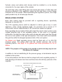
Seaward Products
LP GAS COOKTOP
OWNER’S MANUAL
Installation – Operation - Maintenance
Princess Model 1273
Princess Model 2276
Princess Model 2277
Princess Model 3276
IMPORTANT:
Read all instructions before operating cooktop.
Save the Owner’s Manual / Installation instructions
for local inspector’s use.
PRINCESS MODELS:
Installer:
Provide this manual to the vehicle owner.
1273, 2276, 3276, G3278-1000, G3278-1001
Vehicle Owner:
2277-1000, 2277-1001
Keep this manual for future reference.
2277NS-1002, 2277NS-1103
Serial Number:
WARNING
If the information in this manual is not followed exactly, a fire or explosion may
result causing property damage, personal injury or death.
FOR YOUR SAFETY
Do not store or use gasoline or other flammable vapors and liquids in the vicinity
of this or any other appliance.
WHAT TO DO IF YOU SMELL GAS
•
•
•
•
•
Evacuate all persons from vehicle.
Shut off the gas supply at the gas container or source.
Do not touch any electrical switch, or use any phone or radio in the vehicle.
Do not start the vehicle’s engine or electrical generator.
Contact the nearest gas supplier or qualified service technician, contact
nearest fire department.
• Do not turn on the gas supply until the gas leak(s) has been repaired.
Installation and service must be performed by a qualified installer, service agency
or the gas supplier.
FIRE HAZARD
Do not obstruct the flow of combustion and ventilation air.
PERSONAL INJURY HAZARD
To eliminate the risk of burns or fire by reaching over heated surface units,
cabinet storage space located above the surface unit should be avoided. If
cabinet space is to be provided, the risk can be reduced by installing a range
hood that projects horizontally a minimum of 5 inches beyond the bottom of the
cabinets.
Reaching over a heated cooking surface could result in a serious burn or other
personal injury.
CARBON MONOXIDE POISONING
• Do not use any cooking appliance for space heating because of potential
danger to occupants of the vehicle and damage to the cooktop.
• A window or air vent should be open slightly while using any cooking
appliance. Gas flame consumes oxygen which must be replaced to assure
proper combustion and prevent carbon monoxide.
2
Note to consumer: Have the installer or dealer show you where the main
gas shut off valve is located so that you will know how and where to turn off the
gas supply when necessary.
IMPORTANT INSTRUCTIONS
Save the Owner’s Manual / Installation instructions for local inspector’s use.
NOTE: LPG is heavier than air and if allowed to settle, accumulate and if
ignited WILL CAUSE AN EXPLOSION!!
Install cooktop, cylinder, and regulating system in compliance with ABYC A-1
“Marine LPG – Liquid Petroleum Gas Systems”. For RV applications the
installation must conform to ANSI Standard Z21.57. A copy may be obtained
from the following sources.
FOR MARINE
American Boat & Yacht Council
P.O. Box 806
Amityville, N.Y. 11701
FOR RECREATIONAL VEHICLES (RV)
American National Standards Institute
CSA America
8501 East Pleasant Valley Rd
Cleveland, OH 44131
3
CYLINDER, REGULATING SYSTEM, FUEL LINE
INSTALLATION
CYLINDERS
Cylinders used in LPG systems shall be constructed, tested, marked, maintained
and re-qualified for continued service in accordance with DOT regulations.
No repairs or alterations shall be made on any cylinder.
Cylinders that have been subject to fire or physical damage shall not be returned
to service unless re-qualified.
LPG cylinders shall be permanently and legibly marked in a conspicuous manner
on the outside to show the correct mounting position. The method of mounting
shall be designed to position the cylinder correctly.
The cylinder shall be returned to an authorized fuel distributor for refilling.
Cylinders shipped by land or air freight must be packed and marked in
accordance with DOT regulations.
Only systems using LPG cylinders of the vapor withdrawal type are permitted.
Cylinders designed or installed so as to admit liquefied gas into any other part of
the system are prohibited.
CYLINDER VALVES AND SAFETY DEVICES
Each LPG cylinder shall have manually operated shut-off valve threaded directly
into the cylinder outlet, the valve outlet conforming to CGA connection number
510. The valve shall be equipped with a securely attached hand wheel for
convenient operation without the use of a separate wrench.
For Marine use. A readily accessible shut-off valve or electrically operated
solenoid shall be installed in the low or high pressure supply line to each
attended appliance. The valve or its control shall be operable from within the
vicinity of the appliance and its control readily accessible in the event of a fire at
the appliance. If the cylinder valve is readily accessible from the vicinity of the
attended appliance, the above shut-off valve on the supply line is not required.
All LPG cylinders shall be provided with a safety relief device specifically
designed for LPG as required by DOT regulations.
A threaded protective cap and retaining device to protect the threads of the
cylinder valve during transit and storage shall be supplied.
In addition to the valve required at the cylinder, a dual cylinder system shall be
provided with a two-way positive shut-off valve at the cylinder manifold.
4
Cylinder valves and safety relief devices shall be installed in, or be directly
connected to, the vapor space of the cylinder.
The LPG tank valve outlet fitting does not require pipe dope or Teflon tape and
should be attached to the regulation system nut dry and clean to keep foreign
materials out of the system. When assembling the regulation system, use a high
quality sealant only on all male pipe threads.
REGULATING SYSTEM
Each LPG system shall be provided with a regulating device, specifically
designed for use with LPG.
The LPG regulating device shall be adjusted to deliver gas at any or each
appliance, under varying appliance loads, at a pressure not in excess of 11
inches water column, approximately 0.397 pounds per square inch gauge.
Each regulating device shall be fitted with a high flow check valve located on the
cylinder pressure side of the regulating device. In the event of a regulator
malfunction, the high flow check valve must actuate and control gas flow through
the vent or vent system to the open atmosphere. This check valve must maintain
this gas flow within the designed pressure limits of the vent system.
For Marine use. Each regulating device shall be fitted with a 0 to 250 PSI
pressure gauge. The gauge shall read the cylinder pressure side of the
regulating device. See page 14 for general leak down procedures for RV or
Marine
NOTE: The purpose of the gauge is to provide a quick and easy way to test
the system for leakage.
In addition to, but not substituting for the pressure gauge, a leak detector may be
installed in the system.
A low-side pressure relief device shall be integral with each regulating system. It
shall discharge at between two times and three times the delivery pressure of the
regulator.
REGULATION SYSTEM CONNECTION FITTING
LPG REGULATOR
PRESSURE GAUGE
TANK VALVE HANDLE
RELIEF VALVE
APPLIANCE FUEL
HOSE CONNECTION
LPG FUEL TANK
5
FUEL SUPPLY LINES
The fuel supply line system and its components, as installed, shall be designed
to be compatible with LPG and to withstand the stresses and exposure to the
marine environment. One type is annealed copper tubing, standard type, Grade
K or L, conforming to specifications for seamless copper water tube.
(ASTM B88-75a)
The flexible LPG fuel line shall comply with UL21.
The hose shall have end fittings designed to use with that hose.
Fuel supply lines shall be protected from physical damage and shall be
accessible for inspection.
Fuel supply lines shall be supported by clips or straps or other suitable means to
prevent vibration damage. The clips or straps or other devices shall be corrosion
resistant and shall be designed to prevent cutting, abrading or damage to the
lines and shall be compatible with fuel supply line material.
Fuel supply lines shall be protected by close-fitting grommets, sleeves or
sealants of non-abrasive material wherever they pass through decks, watertight
or waterproof bulkheads and the method used shall be vapor tight. Fuel supply
lines passing through interior bulkheads that need not be watertight shall be
installed so that the bulkheads will not cut, abrade or damage the line.
Fuel supply lines shall be continuous lengths of tubing, piping or hose from the
regulating device, solenoid valve or leak detector to the appliance or to the
flexible section at the appliance. Each appliance shall be served by a separate
supply line which shall originate inside the cylinder housing or locker.
LPG fuel supply lines shall not be used for an electrical ground.
LOCATION – CYLINDER AND CONNECTED DEVICES
LPG cylinders, cylinder valves, safety devices and regulating equipment shall be
located so that escaping vapor cannot reach machinery spaces,
accommodations or other enclosed spaces.
6
INSTALLATION
Installation must conform with local codes or in the absent of local codes, with
the American Standard for Recreational Vehicles, ANSI A119.2 and article 551,
ANSI/NFPA 70. For Marine installation, refer to ABYC standard A-1, A-3, A-26
and A-30.
It is the responsibility of the installer to comply with the insulation clearances
specified on the serial / rating plate. The serial / rating plate is located on the
bottom of cooktop.
Check location where cooktop will be installed. The location should be away
from strong draft areas, such as windows, doors and strong heating vents or
fans.
Princess Model 2276
Attach mounting brackets to the 11 3/8” sides of the cutout. Angled bracket on the wire spring side and the
hemmed bracket on the clamping bracket side.
Princess Model 2277
7
CAUTION
The minimum vertical distance to combustible material above the cooktop is 30
inches. This distance may be reduced to 24 inches if the combustible material
above the cooktop is protected by no less than ¼ inch thick insulating millboard
covered with 28 gauge sheet metal extending 9 inches beyond the sides of the
cooktop and covering the entire bottom of the material to be protected extending
over the top of the cooktop. In lieu of 28 gauge sheet metal, a hood, 28 gauge
sheet metal may be used. Hood shall not be less than the width of the cooktop
and shall be centered over the cooktop and cover the entire bottom of the
material to be protected.
The minimum horizontal distance, outside edge to vertical walls:
Back: 2”
Side: 2”
8
INSTALLATION
1.
2.
3.
4.
5.
6.
7.
Make the cutout.
Insert the cooktop.
Loosen the fastener, bracket (1).
Rotate the bracket (2) outward.
Tighten the fastener, bracket (1).
Screw the installation bolt (3) until the cooktop is secured.
Tighten the locknut (4).
To remove the cooktop, reverse the above sequence.
Bracket Position
Inserting and Removing the Stove
Bottom View
Installation Bolt (3)
Bracket Installation (2)
Bottom View
Fastener Bracket (1)
Locknut (4)
Bracket Position
Stove Installed and Secured
9
•
•
•
•
Place the cooktop upside down on a protected surface.
Remove the paper backing from the foam sealing strip.
Place the strip on the underside of the glass.
Continue until foam strip completely outlines the edges of the cooktop.
Insert the cooktop into the cutout
10
D/C ELECTRICAL CONNECTION
Ignition Wires: Red to (+) Positive
White to (-) Negative
Power Source: 9 to 12 VDC ONLY
*SEE PAGE 1 FOR
MINIMUM HEIGHT
FOR DIMENSION A
Princess Model 3276
Procedure is similar to the model 2276.
The differences being the cutout dimensions and the securement of the unit
1. Locate cooktop according to the installation diagram.
2. Cut out top to dimensions shown.
3. Install the two installation brackets as shown. The top edge of the bracket must be flush to the counter top
surface for the proper engagement of the 3M mounting pads.
4. Set cooktop into cutout. Press down to engage 3M pad on glass top to pad on mounting bracket.
Princess Model 1273
11
LEAK CHECK & LEAK DOWN TEST
Check all connections for gas leaks with a non-corrosive and non-toxic leak
detection fluid. Test the unit by turning on the LPG tank and observing the
pressure gauge. Turn the tank valve off and note the pressure. If there is no drop
on the gauge in 3 minutes, the system is free of leaks.
Ammonia, which is present in some soaps and detergents, attacks brass fittings.
Undetectable at first, in a matter of months these fittings may develop cracks and
leaks.
WARNING
DO NOT USE OPEN FLAME TO CHECK FITTINGS AND GAS LINES FOR LEAKS.
Checking for leaks with an open flame may result in a fire or explosion.
LINE PRESSURE TEST ABOVE ½ PSI
The cook top must be disconnected from the gas supply line system during any
pressure testing in excess of 8 oz. per square inch. (1/2 psi)
TO LIGHT THE BURNERS
1. Push down the knob and turn counterclockwise to “IGNITE” position.
2. Hold the knob down fully until the spark ignites the gas and continue to
hold the knob down for approximately 5 to 10 seconds. The
thermocouple will be heated to activate the safety mechanism.
(**Does not apply to models 2277-1002 & 2277-1003 )
3. Release the knob and set to desired setting.
4. To turn off the burner flame, turn the knob clockwise to “OFF” position.
*Thermocouple is not used in models 2277-1002 & 2277-1003
12
CAUTION
•
•
•
•
•
•
•
•
•
•
•
•
•
Be sure your cooktop is installed properly.
Do not operate cooktop if it is damaged or not working properly.
Do not store flammable materials on or near the cooktop.
Never leave lit burners unattended. A boil-over may result, causing smoke or fire.
Do not use your cooktop for warming or heating the room.
The handle of utensil should be positioned so that it is turned inward but not
extending over adjacent burner.
To reduce the risk of burns and ignition of flammable materials, the burner flame
should not extend beyond the edge of the cooking utensil.
Grease is flammable. Never allow grease to collect around top burners or
cooktop surface. Wipe spillovers immediately.
Only certain types of glass, glass / ceramic, earthware, or other glazed utensils
are suitable for cooktop use without breaking due to sudden change in
temperature.
Do not use water on grease fire. Smother the fire or flame or use baking soda,
multipurpose dry chemical or foam type fire extinguisher.
Children should not be left alone or unattended in area where cooktop is in use.
Children should never be allowed to sit or stand on any part of the cooktop.
Do not heat unopened containers. They could explode.
Do not touch burners, grates or areas near cooktop after use. Units may be hot
even thought it may not be obvious. Areas near burners and grates may become
hot enough to cause burns. During and after use, do not touch, or let clothing or
other flammable material contact cooktop or areas near it until they have had
sufficient time to cool.
CARE AND CLEANING
Regular cleaning with a soft cloth and a warm detergent solution is generally enough to
keep your cooktop clean and beautiful. This is done when the cooktop is cool. Use a
dry cloth or paper towel to clean splatters and spills when surfaces are warm.
GLASS
We recommend the use of HOPE’S CLEANING CREAM for care and maintenance of
the glass surfaces. For more information about this product and a dealer near you,
contact: THE HOPE COMPANY, Inc. (800) 325-4026
STAINLESS STEEL
The best way to clean metal surfaces on your stove is to wipe them down with a damp
cloth, and then dry thoroughly, stubborn spots caused by spillage and discoloration
from heat may be removed by the use of lemon juice, vinegar, or chrome polish. Care
must be used to keep these away from porcelain enamel surfaces. NEVER use coarse
cleaners, steel-wool scouring pads or metal brushes to clean chrome. These will make
deep scratches on chrome. These scratches cannot be removed.
13
EXPLODED VIEW & PARTS LIST
PRINCESS 1273
ITEM NO.
1
2
3
4
5
6
7
8
9
10
PART NO.
75422
75421
80716
73592
75420
75418
80270
75505
75228
75290
DESCRIPTION
Burner Cap
Burner Base
Burner Spill Bowl
Regulator
Burner
Thermocouple
Assy. Glass Top
Bracket, Burner
(Not Shown)
Ignition Module
Manifold
ITEM NO.
11
12
13
14
15
16
17
18
19
PART NO.
72906
73449
75431
75419
75427
75470
73884
80421
73420
DESCRIPTION
Fitting
Cover
Fixing Flange
Gas Valve
Ignition Switch
Fuel Line
Knob Washer
Knob, with Insert
Grate
14
EXPLODED VIEW & PARTS LIST
PRINCESS 2276
ITEM NO.
1
2
3
4
5
6
7
8
9
10
11
12
PART NO.
73420
75422
75421
75420
80716
80292
80421
73884
74075
75417
75419
75431
DESCRIPTION
Grate
Cap, Burner
Burner, Base
Burner
Bowl, Spill
Assy. ,Top
Knob, With Insert
Seal, Knob
Manifold
Switch, Ignition
Valve
Bracket, Valve
ITEM NO.
13
14
15
16
17
18
19
20
21
22
23
24
PART NO.
73666
74144
73251
73204
73120
75505
75462
75470
75418
72906
73592
75228
DESCRIPTION
Cover, Bottom
Bracket, Installation
Grommet
Clip
Spring, Hold Down
Bracket, Burner
Fuel Line, Long
Fuel Line, Short
Thermocouple
Fitting, 3/8” Npt X 3/8” Flare
Regulator
Module, Ignition
1
2
3
4
5
6
7
24
23
22
21
20
19
18
8
9
10
11
12
13
14
17
16
15
15
EXPLODED VIEW & PARTS LIST
PRINCESS 2277-1000, 2277-1001
ITEM NO.
PART NO.
DESCRIPTION
PART NO.
DESCRIPTION
73420
Grate, 7k btu
16
75423
Valve, 10k btu
75422
Cap, Burner 7k btu
17
74383
Manifold
75421
Burner, Base 7k btu
18
73592
Regulator
75420
Injector Holder, 7k btu 19
70192
Manifold, Fitting
80716
Bowl, Spill 7k btu
20
74137
Thermocouple
80421
Knob, With Insert
21
75470
Fuel Line, Short
73884
Grommet
22
75462
Fuel Line, Long
75228
Module, Ignition
23
80402*
Top Assy. Glass (Model 1000)
75417
Switch, Ignition
80590*
Top Assy. S/S (Model 1001)
75419
Valve, 7k btu
24
80717
Spill Bowl, 10k btu
75431
Bracket, Valve
25
75424
Injector, Holder 10k btu
75293
Bracket, Burner
26
75425
Burner, Base 10k btu
80397
Bracket, Mounting
27
75426
Cap, Burner 10k btu
74500
Cover, Burner Box
28
74515
Grate, 10k btu
Not Applicable
* All part numbers are for BOTH models except item #23
ITEM NO.
1
2
3
4
5
6
7
8
9
10
11
12
13
14
15
1
28
2
3
27
4
26
5
25
24
6
23
7
22
21
8
20
19
9
18
10
17
16
11
12
14
13
16
EXPLODED VIEW & PARTS LIST
PRINCESS 2277NS-1002, 2277NS-1003
ITEM NO.
1
2
3
4
5
6
7
8
9
10
11
12
13
14
15
ITEM NO.
PART NO.
DESCRIPTION
PART NO.
DESCRIPTION
73420
Grate, 7k btu
16
75430
Valve, 10k btu
75422
Cap, Burner 7k btu
17
74383
Manifold
75421
Burner, Base 7k btu
18
73592
Regulator
75420
Injector Holder, 7k btu 19
70192
Manifold, Fitting
80722
Bowl, Spill 7k btu
20
Not Applicable
80421
Knob, With Insert
21
75470
Fuel Line, Short
73884
Grommet
22
75462
Fuel Line, Long
75228
Module, Ignition
23
80602*
Top Assy. Glass (Model 1002)
75417
Switch, Ignition
80590*
Top Assy. S/S (Model 1003)
75419
Valve, 7k btu
24
80723
Spill Bowl, 10k btu
75431
Bracket, Valve
25
75424
Injector, Holder 10k btu
75293
Bracket, Burner
26
75425
Burner, Base 10k btu
80397
Bracket, Mounting
27
75426
Cap, Burner 10k btu
74500
Cover, Burner Box
28
74515
Grate, 10k btu
Not Applicable
* All part numbers are for BOTH models except item #23
1
28
2
3
27
4
26
5
25
24
6
23
7
22
21
8
20
19
9
18
10
17
16
11
12
14
13
17
EXPLODED VIEW & PARTS LIST
PRINCESS 3276
ITEM NO.
1
2
3
4
5
6
7
8
9
10
11
12
PART NO.
DESCRIPTION
80298
Assy. Top, Black
80421
Knob, With Insert
73884
Grommet
75228
Module, Ignition
75462
Fuel Line, Left Rear
75418
Thermocouple
75470
Fuel Line, Right Rear
Not Applicable
75239
Manifold
73782
Cover, Bottom
73719
Bracket, Installation
72543
Manifold, Fitting
ITEM NO.
13
14
15
16
17
18
19
20
21
22
23
24
PART NO.
73719
75431
75419
75470
75505
80716
75420
75421
75422
73420
73592
70192
DESCRIPTION
Bracket, Installation
Bracket, Valve
Valve
Fuel Line, Left Front
Bracket Burner Mount
Bowl, Spill
Burner
Burner Base
Burner Cap
Grate
Regulator
Fitting
18
EXPLODED VIEW & PARTS LIST
PRINCESS GOURMET G3278-1000, G3278-1001
ITEM NO.
1
2
3
4
5
6
7
8
9
10
11
12
13
PART NO.
80668
80696
75315
75470
75462
75470
75470
75291
75228
75505
75423
75426
75425
75424
DESCRIPTION
Assy. Top, Glass
Assy. Top, SS
Cover Bottom
Fuel Line Left
Fuel Line Top Left
Fuel Line, Right
Burner Bracket Large
Manifold
Ignition Module
Burner Bracket Small
Valve 10K BTU
Burner Cap Large
Burner Base Large
Injector Holder Large
ITEM NO.
14
15
16
17
18
19
20
21
22
23
24
25
26
27
PART NO.
74515
80717
74250
75418
75431
75419
75422
75421
75420
80716
73884
73719
73592
70192
DESCRIPTION
Grate Large
Large Spill Bowl
Knob
Thermocouple
Valve Bracket
Valve 7K BTU
Burner Cap Small
Burner Base Small
Injector Holder Small
Small Spill Bowl
Seal Knob
Mounting Bracket
Regulator
Manifold Fitting
G3278-1001 PARTS LIST
19
LIMITED TWO YEAR WARRANTY
SEAWARD PRODUCTS warrants the products delivered will be:
A. Free from (1) encumbrances and (2) defects in material and workmanship under the normal use and
service.
B. Will meet applicable specifications and descriptions at time of delivery to BUYER.
The obligation of SEAWARD under this warranty is limited to the repair,
Rework, or replacement, at SEAWARD’S option, any part or component thereof, which examination
discloses to our satisfaction to have been nonconforming or defective. SEAWARD, after establishing
customer’s purchase date and determining problem to be under warranty, will either repair the product at
their factory or authorized service center and allow labor and parts for (2) two years from purchase date.
Transportation charges are the responsibility of the customer. Conditions not covered under warranty are:
(1) Porcelain Enamel
(2) Glass
(3) Routine maintenance that may be required
The foregoing warranty and condition shall apply to any repaired, reworked, or replaced products, part or
component supplied by SEAWARD and shall in no event be liable to BUYER or BUYER’S customers for any
incidental or consequential damages, or loss of use, or other losses, however occasioned.
Implied warranties of merchantability and of the fitness of the product for any purpose are warranted for a
period of two years on parts and labor.
SEAWARD makes no warranties, expressed or implied after that time.
Some states do not allow limitation on how long an implied warranty lasts or for the exclusion or
limitations of incidental or consequential damages, therefore, the above limitations may not apply to you.
This warranty is extended to the original purchaser only, unless purchased for purpose of resale. This
warranty gives you specific legal rights, and you may also have other rights which vary from state to state.
Seaward Products
REPAIR PARTS
Repair parts listed herein may be ordered through Seaward Products. Seaward Distributors and
Dealers, or Dealer’s Authorized Service Centers. All parts will be shipped at prevailing prices.
When ordering repair parts, please give the following information:
(1) The part number
(2) The part description
(3) The model number of the cooktop
(4) The serial number of the cooktop
The model number and serial number of the water heater will be found on the rating plate located on
the front panel. For the Authorized Service Center nearest you, please contact Seward Products.
Seaward Products
3721 Capitol Avenue
Whittier, CA 90601-1732
Tel. (562) 699-7997 Fax. (562) 699-0908
www.seawardproducts.com
20
03-07 #75416