1
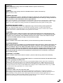
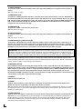
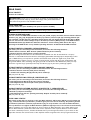
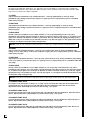
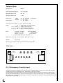
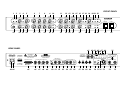
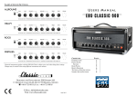
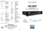
OPERATOR'S MANUAL
G AIN
CRUNCH 1
BASS
MIDDLE
TREBLE
TREBLE
BAL ANCE
REVERB
CLEAN
VOLUME
CRUNCH 1
VOLUME
PRESENCE A
PRESENCE B
SAVAGE
BRIGHT
CRUNCH
BOOST
PRESHAPE
TR.BAL.
ACTIVE
CLEAN
CRUNCH1
DEPTH
BOOST
DEPTH
BOOST
PRES.
A/B
SPEAKER
A/B
INPUT
G AIN
LEAD
LEAD
BOOST
BASS
MIDDLE
TREBLE
TREBLE
BA L ANCE
REVERB
ROUGH /
SMOOTH
CRUNCH 2
VOLUME
LEAD
VOLUME
CRUNCH2
L EAD
special edition
REVERB
ACTIVE
MIDI
MODE
STANDBY
MASTER A
POWER
MASTER B
MASTER
A/B
CHANNEL TRIODE /
PENTODE
1/2
SAVAGE
special edition
Please, first read this manual carefully!
Congratulations!
You chose an excellent product, the ENGL SAVAGE special edition,
a quality advanced all-tube guitar head that sets a new standard for
sound technology and versatility in the high-end sector.
This amp is the product of a concentrated effort; all of us here at ENGL
invested all our experience and innovative ideas in the design and
construction of this amp.You are now the owner of one of these
quality heads and we think congratulations are definitely in order:
2
EDMUND ENGL,
Product concept and realization, production and
assembly line design, mechanical construction and
electronic layout (via CAD), soundcheck, production
control.
HORST LANGER,
Idea, concept, technical and electronic design,
acoustic research, electronic finishing and author/typist
of this operator’s manual, graphics and layout.
BEATE AUSFLUG,
Procurement, sales and financing
Short preliminary description:
The ENGL SAVAGE special edition is on the cutting edge of modern guitar technology,
it boasts a number of efficient features and operating modes: four channels, Clean, Crunch 1,
Crunch 2 and Lead assigned to two main channels, each featuring an individual voicing section.
Four gain pots and a separate volume control for each channel allow for precision-tuning
between channels. The Rough/Smooth mode selector for the Crunch 2 and Lead channels
generates two completely different types of overdrive which produce two distinctive tonal
variations: Rough for loads of upper-end grit and powerful bottom-end; Smooth for creamy
mids with plenty of punch. This feature plus the four channels lets you access six individual
sound modes! Additionally, diverse switching functions allow you to shape the main channels'
tonal characteristics to your taste. Furthermore the two poweramp operating modes Triode
and Pentode and the option of switching between two different speaker cabinets enhance this
amp´s tonal spectrum. The power amp's two voicing sections and two master volume controls
have proven to be both practical and effective. These, along with the channels and a several
other features, can be selected and accessed via the front panel, a footswitch or a MIDI
switching system. By means of the ENGL MIDI Interface (optional), these features can be
controlled via a MIDI pedal board and the settings for switching functions can be programmed
in up to 99 memory locations. This amp also features a number of signal paths: a passive
parallel/serial (!) FX loop for each main channel or a switchable master FX loop, a variable
balanced line out featuring speaker simulation and an overload LED, as well as selectable 4,
8 and 16 Z speaker outputs for numerous cabinet connection options. Yet another handy tool
is the "ENGL Impedance Test and Cable Check System": This unique feature helps you to check
speakers´ impedances and cables equipped with 1/4" plugs!
The integrated ECS (Emergency Circuit System) protects the amp from damage due to power
tube defects/failure and ensures the amp continues to function at reduced power until the
failed tube can be replaced.
Superior craftsmanship and finishing, quality components are what this device is all about.
However, keep in mind that a few precautions will radically extend tube life!
PLEASE NOTE:
Read the Operator’s Manual carefully and thoroughly, especially the following Handling
and Care section as well as the framed guidelines. Avoid operating errors and potential
damage to the amp by heeding the guidelines and cautionary remarks in this manual. It also
covers a few convenient pointers and interesting tips on several functions. These are located
under the respective function´s description. This manual covers all the features, operational
guidelines, technical specifications and many helpful hints and tips. It should answer all your
questions, so keep it in a safe place and refer to it when necessary.
Handling and Care
Protect the amp from mechanical knocks (tubes!).
Let the amp cool down before you transport it (app.10 minutes).
Tubes need about 20 seconds to warm up after you switch the power on,
and a few minutes more before they reach their full power capability.
Avoid storing the amp in damp or dusty rooms, they are hard on jacks,
switches and potentiometers.
Make sure air can circulate at the front and top of the amp
to allow for adequate cooling (increases component life).
Never operate the amp without an adequate load.
Replace tubes with select ENGL replacement tubes (special selection criteria) to avoid
microphonic properties, undesirable noise and unbalanced response.
Please also note the item printed on page 13!
3
FRONT PANEL
Explanation:
*MCH 1 (Main Channel 1)
Pushbuttons/Controls marked with *MCH 1 are assigned to Main Channel 1
and are only active in this channel.
*MCH 2 (Main Channel 2)
Pushbuttons/Controls marked with *MCH 2 are assigned to Main Channel 2
and are only active in this channel.
*P.A. Section (Power Amp Section)
Pushbuttons/Controls marked with *P.A.Section are assigned to the poweramp section
and are only active there.
1 BRIGHT
*MCH 1; Alters the EQ by boosting the upper treble range in the Main Channel 1;
effectiveness decreases at higher GAIN (1) settings.
Tip: For a crisp glassy tone, set the Bright switch to the On position. This setting boosts
the treble response of muddy pickups.
2 PRESHAPE
*MCH 1; Two different filtering characteristics can be preset:
Off position: cuts the midrange.
ON position (pushed in): boosts the low midrange.
Tip: The Off-positions is ideal for bright, funky chords and riffs complete with a tight bottom end.
The activated function delivers a very warm and fat tone. You can also use this feature to
equalize the amp's sound characteristics to adapt it to different pickups.
3 GAIN
*MCH 1; Input sensitivity control for the Clean and the Crunch 1 channels.
Tip: GAIN settings depend on what type of pickups are installed in your guitar. The recommended setting
for humbuckers or active pickups lies between the 11 and 2 o’clock positions and 1 to 4 o’clock for single
coils for a pure clean response. Moreover, increased gain will produce a touch of overdrive in the preamp.
If your pickups are of the ultra-high output variety you may have to back off the guitar’s volume to
achieve a truly clean tone. It may be advisable to reduce the Bass level when operating with high gain
and volume levels to achieve a Clean response.
4 CRUNCH BOOST
*MCH 1; Boosts the signal in the Crunch 1 channel, with primary emphasis on the bottom end.
Tip: For example, this feature can be used in combination with the Preshape (2) control to achieve a tonal
balance between the Clean and the Crunch 1 channels: Preshape Off -> Crunch Boost On; Preshape ON ->
Crunch Boost Off. Other applications: You can select alternative sounds featuring a heavier bottom end
for pickups with thin bass response or shape the response to suit your taste.
5 CRUNCH1
*MCH 1: Additional sensitivity control feature for the Crunch 1 mode; allows you to increase and
decrease the signal level for the Crunch 1 channel and balance its gain in relation to the Main Channel´s
Gain (3) setting.
Tip: The Crunch 1 channel is ideal for marginal to medium distortion. Response is extremely dynamic;
mildly overdriven sounds can be attained at Crunch 1 settings between 11 and 2 o'clock, depending on
the setting of the Gain control (3). Furthermore you have the option of dialing in a different Clean sound
in the Crunch 1 channel by adjusting this control to the 9 o´clock position. By using the Crunch Boost
switch and the Treble Balance control, you can shape the tone to provide a contrast to the
Clean channel´s tone.
6 BASS
*MCH 1; Bottom end voicing control for the Main Channel 1 (Clean and Crunch 1).
Tip: To get an idea of this amp's capabilities, we suggest you set all control pots to the 12 o'clock position
and then adjust the sound according to your taste, the connected speakers and the room's ambience.
The operating mode of this EQ is passive; it is located in the preamp stage and therefore affects
the FX Loop´s send signal.
4
7 MIDDLE
*MCH 1; Mid-range voicing control for the Main Channel 1 (Clean and Crunch 1).
Tip: (see section 6, Tip!)
8 TREBLE
*MCH 1; Upper range voicing control for the Main Channel 1 (Clean and Crunch 1).
Tip: (see section 6, Tip!)
9 TREBLE BALANCE
*MCH 1; Treble balance control, operable in the Crunch 1 channel only. This control allows you to boost
or cut the high end in relation to the amount of treble determined by the Treble (8) -setting. Activate this
control by means of the Treble Balance Active (10) pushbutton.
Tip: If you have dialled in a very bright Clean sound (Treble control at the 3 o'clock position or higher),you
may want to reduce the amount of treble for the Crunch 1 channel to avoid a shrill Crunch sound.
This
feature can also be helpful in avoiding unintentional feedback between the speaker and the guitar.
10 TREBLE BALANCE ACTIVE
*MCH 1; This pushbutton activates the Treble Balance (9) control in the On position (pushed in).
Tip: If you want the treble response to be identical in both the Crunch 1 and the Clean channels,
leave this pushbutton in the Off position; now the Treble Balance (9) control is inactive. Also use this
setting if you prefer to adjust the treble via your guitar's tone control.
11 REVERB
*MCH 1; Reverb control, adjusts the portion of the reverb signal and increases reverb intensity in the
main channel 1 when you rotate it clockwise; the reverb can be switched on via the Reverb Active (22)
pushbutton. The red LED above this pushbutton indicates the reverb is active. The reverb can also be
switched via the MIDI Interface Port (45), or the footswitch jack (49).
12 CLEAN VOLUME
*MCH 1; Volume control for the Clean channel. (in front of the FX loop, affects the Send level)
13 CLEAN/CRUNCH 1
*MCH 1; Channel selector pushbutton for switching between Clean and Crunch 1 modes. Off position: the
Clean channel is active; On position (pushed in): the Crunch 1 channel is active when the main channel
selector pushbutton (39) is in the Off position (Main Channel 1) in both cases. An LED located next to the
respective channel's volume control illuminates when the channel is activated. Clean channel: green LED,
Crunch 1 channel: yellow LED. This feature can also be switched via the MIDI Interface Port (45), or the
footswitch jack (46); the channel selector pushbutton is deactivated once a footswitch is connected to
the footswitch jack (46).
14 CRUNCH 1 VOLUME
*MCH 1; Volume control for the Crunch 1 channel. (in front of the FX loop, affects the Send level)
15 MIDI MODE
This red LED illuminates when the ENGL MIDI Interface is connected and activated; the LED flashes when
the amp is operating in the MIDI mode.
Tip: The ENGL MIDI Interface offers even more comfortable handling features and loads of interesting
combinations. This interface allows you to switch the defined functions via a MIDI stage board. You can
also save diverse sound combinations as presets in up to 99 MIDI memory locations, assign polychannels
1-8 via the interface and control another ENGL device equipped with an MIDI Interface Port; e.g. an ENGL
rack stereo power amp, type 930 (-> for a stereo setup!).
16 PRESENCE A
*P.A.Section; Treble control A in the power amp.
Tip: Use two controls A and B and the respective Depth Boost pushbuttons to adjust two different
sound settings in the poweramp. This feature enhances the sound variations of the amp because you can
assign both EQs to every channel and to the Rough and Smooth modes. Another application is a
combination with two different speaker cabinets (a seperate tone control setting for cabinet A and B) or
different sound settings for Triode and Pentode operation modes.
5
17 DEPTH BOOST
*P.A.Section; Boosts the bottom end in the power amp; this pushbutton is assigned to the Presence A
control.
Tip: (see section 16, Tip!)
18 PRESENCE A/B
*P.A.Section; Switches between Presence A and Presence B; the active Presence control is identified by
the illuminated LED next to the respective control. Red LED: Presence A (16) and Depth Boost (17); green
LED: Presence B (19) and Depth Boost (20), This feature can also be switched via the MIDI Interface Port
(45), or the footswitch jack (48); the channel selector pushbutton is deactivated once a footswitch is
connected to the footswitch jack (48).
19 PRESENCE B
*P.A.Section; Treble control B in the power amp
Tip: (see section 16, Tip!)
20 DEPTH BOOST
*P.A.Section; Boosts the bottom end in the power amp; this pushbutton is assigned to the Presence B
control.
Tip: (see section 16, Tip!)
21 SPEAKER A/B (=OUTPUT A/B)
*P.A.Section; This pushbutton switches between speaker output A (74) and speaker output B (75), if
speakers are connected to both output jacks. The red LED above the pushbutton indicates "speaker B
active". This feature can also be switched via the MIDI Interface Port (45), or the footswitch jack (49); the
pushbutton is deactivated once a footswitch is connected to the footswitch jack (49).
IMPORTANT: When operating the amp together with one speaker cabinet, always connect it to Output
A/ Master (74)! If no cabinet is connected to Output B (75), the switching function is disabled. Ensure
cabinets or speaker systems bear the same impedance at Output A and Output B: e.g. cabinet at Output
A =8 ohms and cabinet at Output B=8 ohms! Never operate the poweramp without a sufficient load!
Tip: The speaker switching feature is ideal for driving two speaker cabinets with different response. One
recommended combination would be a closed 4 x 12" cabinet together with an open 4 X 10" cabinet. This
feature offers a number of interesting sound variations.
22 REVERB ACTIVE
This pushbutton activates the integrated spring reverb system. A red LED above the the pushbutton
indicates the reverb is active. This pushbutton's primary significance is during MIDI programming via the
MIDI Interface (if connected). Use it to assign the internal reverb signal to different MIDI presets. Adjust
the reverb portion with the respective Reverb controls in both main channels. Reverb can also be
switched via the MIDI Interface Port (45), or the footswitch jack (49); the pushbutton is deactivated once
a footswitch is connected to the footswitch jack (49).
23 INPUT
Unbalanced 1/4" input jack
24 GAIN
*MCH 2; Input sensitivity control, functions as pre-gain for the Crunch 2 and the Lead channel and
defines the amount of (preamp-) overdrive in the Crunch 2 channel.
Tip: The Crunch 2 channel sounds more refined and the mid response is harder than in Crunch 1. It is ideal
for playing fast riffs. In conjunction with higher Gain settings and powerful pickups, this channel can be
suitable for playing lead.
25 LEAD BOOST
*MCH 2; Boosts the degree of distortion in the Lead channel, with primary emphasis on the bottom end.
Tip: When you are using high Gain and Lead settings, we recommend that you leave this pushbutton in
the Off position to avoid a spongy bass response. In Lead mode with medium Gain settings (Gain and
Lead controls between the 11 and 1 o'clock's position), the activated Lead Boost delivers softer mids,
more bass punch and plenty of sustain.
6
26 LEAD
*MCH 2; Controls the amount of distortion in the Lead mode; the Gain (23) and Lead controls
are used to define the relationship between the Crunch and Lead signals.
CAUTION: Extremely high gain and volume levels in the Crunch and Lead mode can produce
strong feedback. Avoid feedback squeals, they lead to hearing loss and damaged speakers!
27 BASS
*MCH 2; Bottom end voicing control for the Main Channel 2 (Crunch and Lead).
Tip: To get an idea of this amp's capabilities, we suggest you set all control pots to the 12 o'clock position
and then adjust the sound according to your taste, the connected speakers and the room's ambience.
The operating mode of this EQ is passive; it is located in the pramp stage and therefore it affects the send
signal at the FX Loop.
28 MIDDLE
*MCH 2; Mid-range voicing control for the Main Channel 2 (Crunch and Lead).
Tip: (see point 26, Tip!)
29 TREBLE
*MCH 2; Upper range voicing control for the Main Channel 2 (Crunch and Lead).
Tip: (see point 26, Tip!)
30 TREBLE BALANCE
*MCH 2; Treble balance control, operable in the Smooth mode only. This control allows you to boost
or cut the high end in relation to the amount of treble determined by the Treble (28) -setting.
31 ROUGH/SMOOTH
*MCH 2; Switches between two completely unique overdrive characteristics in the Crunch 2 and Lead
channels. Rough: emphasis on high and low ends. Smooth: emphasis on midrange, suppresses the gritty
upper frequencies. A red LED above the pushbutton denotes the Smooth mode is active. This feature can
also be switched via the MIDI Interface Port (45), or the footswitch jack (47); the channel selector
pushbutton is deactivated once a footswitch is connected to the footswitch jack (47).
Tip: The Rough sound character (heavy) is great for rhythm playing with a pronounced bottom end and
gritty, biting highs. You should use the Bass knob (27) and the Depth Boost buttons (17 or 20) sparingly
in conjunction with this feature (especially if you connect a 4 x 12" cabinet).
The Smooth sound character is most effective for lead-playing. In spite of its creamy tube tone, its
pronounced mids deliver enough punch to cut through! Try Presence settings between 11 and 3 o´clock
and activate the Depth Boost. Extremely high gain and volume levels can produce strong feedback
between the speakers and your guitar´s pick ups. Cut back on the Gain, Treble and Presence settings to
avoid undesirable feedback.
32 REVERB
*MCH 2; Reverb control, adjusts the portion of the reverb signal and increases reverb intensity in the
main channel 2 if you rotate it clockwise; the reverb can be switched on via the Reverb Active (22)
pushbutton. The red LED above this pushbutton indicates the reverb is active. The reverb can also be
switched via the MIDI Interface Port (45), or the footswitch jack (49).
33 CRUNCH 2 VOLUME
*MCH 2; Volume control for the Crunch 2 channel. (in front of the FX loop, affects the Send level)
34 CRUNCH 2/LEAD
*MCH 2; Channel selector pushbutton for switching between Crunch 2 and Lead modes. Off position: the
Crunch 2 channel is active; On position (pushed in): the Lead channel is active when the main channel
selector pusbutton (39) is in the On position (Main Channel 2) in both cases. An LED located next to the
respective channel's volume control illuminates when the channel is activated. Crunch 2 channel: yellow
LED, Lead channel: red LED. This feature can also be switched via the MIDI Interface Port (45), or the
footswitch jack (47); the channel selector pushbutton is deactivated once a footswitch is connected to
the footswitch jack (47).
35 LEAD VOLUME
*MCH 2; Volume control for the Lead channel. (in front of the FX loop, affects the Send level)
7
36 MASTER A
*P.A.Section; Master volume A for power amp output.
Tip: The two Master volume controls offer a few practical applications: adjust two different volume
levels in the poweramp and assign them to the four channels and the Rough and Smooth modes. Another
application is a combination with the two poweramp operating modes Triode and Pentode: Set the
desired volume level with one Master for the Pentode mode. With the other Master, adjust a very high
level that generates a great overdrive sound in poweramp Triode mode.
37 MASTER A/B
*P.A.Section; Switches between Master A and Master B; the active Master control is identified by an LED
next to the respective control, red LED: Master A (36); green LED: Master B (38). This feature can also be
switched via the MIDI Interface Port (45), or the footswitch jack (48); the channel selector pushbutton is
deactivated once a footswitch is connected to the footswitch jack (48).
38 MASTER B
*P.A.Section; Master volume B for power amp output.
Tip: (see point 36, Tip!)
39 CHANNEL
Main Channel selector pushbutton; selects Main Channel 1 or 2 and, depending on the other channel
selector pushbutton settings (13 and 34). It activates the Clean, Crunch 1, Crunch 2 or Lead channels.
Off position: Main Channel 1 (Clean or Crunch 1), On position (pushed in): Main Channel 2 (Crunch 2 or
Lead). This feature can also be switched via the MIDI Interface Port (45) or the footswitch jack (46): the
channel selector pushbutton is deactivated once a footswitch is connected to the footswitch jack (46).
40 TRIODE PENTODE
*P.A.Section; Switches between Triode and Pentode operating modes in the poweramp. The red LED
above the pushbutton denotes Pentode mode. This feature can also be switched via the MIDI Interface
Port (45).
Tip: Use the both poweramp modes as follows: 1. To reduce the output power in Tride mode to
approx. 1/2 of the Pentode power. Now you can generate excellent poweramp overdrive at a reasonable
volume level. 2. The two modes generate a different spectrum of overtones which alters the sound: In
combination with the four channels and sound modes, the two poweramp operating modes offer a wide
range of sound variations. The Triode mode has pronounced mids and sounds warm and creamy. The
close the poweramp gets to to the overdrive threshold, the more intense this effect becomes. Pentode
mode emphasizes bass and treble response, the sound character becomes somewhat more brittle and
refined.
41 STAND BY
Poweramp standby switch. Use this feature during a break; the amp is ready to perform immediately
because there delay while the tubes heat up. In order to conserve energy, we recommend that you
switch the amp off (42) during a lengthy break.
42 POWER
AC power on/off.
8
REAR PANEL
43 AC SOCKET
Connect AC cord here
ATTENTION: Ensure you use an intact AC cord with an insulated plug only!
Before you power the amp up, ensure the voltage value printed beside the
AC socket corresponds to the available current.
44 AC FUSE BOX
Contains mains fuse (rear chamber) and spare fuse (front chamber)
NOTE: Ensure replacement fuses bear identical ratings (refer to the table)!
45 MIDI INTERFACE PORT
You can connect the ENGL MIDI Interface to this jack (Sub D, 25 pins) and then execute channel selection
functions (13), (34), (39), Rough/Smooth mode (31) selection, Presence A/B (18) switching, Master A/B
(37) switching, speaker A/B (21) switching, Reverb Active (22) and Triode/Pentode mode (40) via MIDI.
You can also save the switch settings in up to 99 memory locations (MIDI presets) of the MIDI inteface.
The MIDI Mode LED (15) illuminates when the interface is active. Flashing LEDs denote the amp is
operating in the MIDI mode. A very detailed operating manual is included with the MIDI Interface.
46 FOOTSWITCH: CHANNEL; CLEAN/CRUNCH 1
1/4" stereo jack for connecting a dual footswitch; it executes the following functions:
1. Main channel selection, Main Channel 1/Main Channel 2 (mono terminal).
2. Channel selection: Clean/Crunch 1 (stereo terminal).
Tip: All switching functions that can be switched via footswitch can also be executed via a Looper/
switcher or other MIDI device that features 8 freely-programmable switching inputs. Depending on the
type of MIDI device, you may have to split the Footswitch stereo jacks into eight mono jacks. Each
switching function requires a mono or stereo contact (see 46, 47, 48 and 49 for pin assignments) and
the ground! NOTE: If the switching and signal grounds are identical in the MIDI device, then you may
encounter a gound loop, especially if the amp and device (e.g. FX processor) exchange signals!
47 FOOTSWITCH: CRUNCH 2/LEAD; ROUGH/SMOOTH
1/4" stereo jack for connecting a double footswitch executes the following functions:
1. Channel selection: Crunch 2/Lead (mono terminal).
2. Sound mode switching Rough/Smooth (stereo terminal).
Tip: (see point 46, Tip!)
48 FOOTSWITCH: MASTER A/B, PRESENCE A/B
1/4" stereo jack for connecting a dual footswitch; it executes the following functions:
1. Switching between Master A/B control (mono terminal).
2. Switching between Presence A/B control (stereo terminal).
Tip: (see point 46, Tip!)
49 FOOTSWITCH: REVERB; OUTPUT A/OUTPUT B (= SPEAKER A/B)
1/4" stereo jack for connecting a dual footswitch; it executes the following functions:
1. Reverb on/off (mono terminal).
2. Switching between the two speaker/poweramp Outputs A and B (stereo terminal).
Tip: (see point 46, Tip!)
50 FX LOOP STATUS
This switch assigns the two FX loops to the two Main Channels. Off position: Master Loop (common FX
loop), activates the FX Loop Channel 1 (common signal processor for all channels); On position (pushed
in): Channel 1/Channel 2 selection (separate FX loops), FX Loop Channel 1 is active for Main Channel 1,
FX Loop Channel 2 is assigned to Main Channel 2 (different signal processors for the two main channels).
Tip: For example, you can use this feature to insert a chorus to Main Channel 1 and a delay with a noise
gate to Main Channel 2; different effect levels can be adjusted via the separate Balance controls. When
you insert a multi-FX processor, activate the Master FX Loop and assign the effects of your choice to the
respective channels and sound modes of the amplifier. Effects assignment has to be programmed at the
9
FX device itself. With this application, you will find it very comfortable to control the amp via MIDI and
the ENGL MIDI Interface: All of the amp's MIDI functions can be switched at the same time with the MIDI
FX processor's effects via a MIDI footpedal!
51 SEND
Signal output for the Master Loop or Main Channel 1´s FX Loop (Depending on FX Loop Status
pushbutton (50) setting). Connect this output to a signal processor’s input/return jack via a shielded
cable with 1/4" plugs.
52 RETURN
Signal input for the Master Loop or Main Channel 1´s FX Loop (Depending on FX Loop Status
pushbutton (50) setting). Connect this input to a signal processor’s output/send jack via a shielded cable
with 1/4" plugs.
53 BALANCE
FX mix control for the Master Loop or Main Channel 1´s FX Loop (Depending on FX Loop Status
pushbutton (50) setting): Rotate the knob to the Dry position for the dry amp signal, i.e. no effect on the
signal. Turn clockwise to blend in an effect connected to the loop with the dry signal (parallel/passive).
When the control is set all the way to the Effect position, only the wet signal, i.e. the signal sent from the
FX device, is routed to the power amp (serial/passive).
NOTE: If you do not connect an effects processor to this loop, set this control to the Dry position!
54 SEND
Signal output for the Main Channel 2´s FX Loop (only active when FX Loop Status pushbutton (50)
setting is set to CH 1/CH 2!). Connect this output to a signal processor’s input/return jack via a shielded
cable with 1/4" plugs.
55 RETURN
Signal input for the Main Channel 2´s FX Loop (only active when FX Loop Status pushbutton (50) setting
is set to CH 1/CH 2!). Connect this input to a signal processor’s output/send jack via a shielded cable with
1/4" plugs.
56 BALANCE
FX mix control for the Master Loop or Main Channel 2´s FX Loop (only active when FX Loop Status
pushbutton (50) setting is set to CH 1/CH 2): Rotate the knob to the Dry position for the pure amp signal,
i.e. no effect on the signal. Turn clockwise to blend in an effect connected to the loop, to the dry signal
(parallel/passive). At the Effect position, only the wet signal, i.e. the signal sent from the FX device is fed
to the power amp (serial/passive).
NOTE: If you do not connect an effects processor to this loop, set this control to the Dry position!
57 POWER TUBE FUSE
Fuse (refer to the description of the E.C.S. on page 13) for the left power tube (the far left tube when
viewed from the rear of the chassis); the LED above the fuse illuminates when this fuse is blown.
Replacement fuses (160 mAM) are located at the housing´s rear panel.
58 POWER TUBE FUSE
Fuse for the second power tube (second from left); the LED above the fuse illuminates when this fuse is
blown. Replacement fuses (160 mAM) are located at the housing´s rear panel.
59 POWER TUBE FUSE
Fuse for the third power tube (second from right); the LED above the fuse illuminates when this fuse is
blown. Replacement fuses (160 mAM) are located at the housing´s rear panel.
60 POWER TUBE FUSE
Fuse for the right power tube (the far right tube); the LED above the fuse illuminates when this fuse is
blown. Replacement fuses (160 mAM) are located at the housing´s rear panel.
10
61 CABLE RETURN
Connect one end of a cable with 1/4" plugs to this jack, the other end to jack 62. Only Mono cables can
be tested with this feature.
Tip: This test circuit is a very useful tool: You are able to test speaker cables as well as guitar cables and
patch cables (only the mono wire is tested!) for FX device connections. Due to the higher resistance of
longer cables you may find that the 12 Z LED instead of the 8 Z LED indicates that the cable is O.K.
62 TEST JACK
Connect a speaker cabinet(s) to this jack for an impedance check. For the cable test, insert one end of
the cable to this jack.
IMPORTANT: Before testing a cable, make sure that the other end of this cable is not connected to a
poweramp output; this may damage the test circuit. Even a cabinet that features a Thru jack
may not be connected to a poweramp output. It is OK to connect it to another. Disconnect the
cable or the cabinet after the test to avoid unnecessary strain on the internal power circuit.
PLEASE NOTE: During the impedance check, you may find that several LEDs illuminate or flicker at the
same time. Possible causes: the connection between the plug and the jack is faulty or a high level of
peripheral noise is generating voltage in the speakers that influences the test circuit. Due to the
measuring method, deviations in values are possible. The speaker's DC resistance provides delivers an
approximation of a the exact value. This circumstance explains why you might encounter a discrepancy
between the displayed and the true value. When you are sure about the impedance of a cabinet (or of
several interconnected cabinets), use this value to set the impedance selector (76) to the correct position.
In practice,the displayed value should not vary more than one LED bar from the true value. Use thick,
short cables for the impedance test to avoid faulty measurements due to higher cable resistance.
63 < 4 Z; CABLE SHORT CIRCUIT
This red LED flashes to indicate the following results during the impedance check: an impedance lower
than 4 ohms, possibly a shortcircuit in the connector cable (test the cable separately!), or a shortcircuit
inside the cabinet. During the cable check, it indicates a shortcircuit between the wires or in one of the
plugs.
64 4 Z
This green LED indicates an (overall) impedance of 4 ohms during the impedance check.
65 6 Z
This yellow LED indicates the following results during the impedance check: a relatively unusual (overall)
impedance of 6 ohm. Possible cause: A speaker's tolerance (it may be an 8 ohm system), faulty cables, or
poor connections between plugs and jacks (in this case, it may be a 4 ohm system), or a parallel circuit
consisting of three 16 ohm speakers.
66 8 Z; CABLE O.K.
This yellow LED indicates the following results during the impedance check: an (overall) impedance of 8
ohms. During the cable check, it indicates cable is intact.
67 12 Z
This yellow LED indicates the following results during the impedance check: a relatively unusual (overall)
impedance of 12 ohms. Possible cause: A speaker's tolerance (it may be a 16 ohm system), faulty cables
or poor connections between plugs and jacks (in this case it may be an 8 ohm system), or a serial circuit
consisting of a 4 ohm and an 8 ohm speaker.
64 4 Z
This green LED indicates an (overall) impedance of 16 ohms during the impedance check.
69 > 16 Z; CABLE BREAK
This red LED flashes to indicate the following results during the impedance check: an impedance greater
than 16 ohms, possibly a break in the connector cable (test the cable separately!), or a break the
cabinet's internal wiring. During the cable check, it indicates a break in the wires or in one of the plugs.
inside the cabinet. During the cable check a break in the wires or in one of the plugs.
11
70 LEVEL
Signal level control for the frequency-corrected line output; use it to match the amp’s signal level at the
Line output to the mixing console or recorder’s input.
Tip: The Line Out's output level is influenced by the following factors: 1. in the PREAMP setting, by the input
level (Gain, Crunch, Lead), the Volume control settings for the various channels and to some degree by
voicing control settings. 2. in the Poweramp setting, as above with the addition of the Master settings.
First dial in the desired sound combination at the front panel. Then adjust levels for FX devices and signal
processors (if connected). Now use the Level control to adjust the level. The Line output is not overloaded
until the Overload LED illuminates brightly and continuously. You can push the level up to this point to
match a mixer desk's or recorder's input level requirement. Use the respective device's input sensitivity or
gain control to fine-tune level adjustments.
71 LINE OUT STATUS
Selects the Line output mode. Off position: the Line signal is routed from the poweramp output, (Stand By
activated!), On position (pushed in): the Line signal is routed from the SAVAGE 's preamp.
Tip: The SAVAGE's preamp and power amp supply two different signals: The Presence control, the Depth
Boost switch, the power tubes and the output transformer in the power amp stage influence the final tone.
You may need to adjust the voicing controls at your amp, mixer desk or recorder when identical tones are
desirable.
72 OVERLOAD
This LED denotes the Line output is overloaded; in this case, reduce the signal’s level via the Level
control.
73 LINE OUT BALANCED & FREQU.-COMPENSATED
The frequency-corrected, balanced Line output jack (XLR). (Pin 2 and 3 signal, Pin 1 = N.C. ).
Its signal simulates a 4 x 12" speaker cabinet.
74 POWERAMP OUTPUT A; MASTER
Poweramp output A or Master output. You must connect a speaker cabinet to this jack before you
operate (activate) the poweramp.
IMPORTANT: When you operate the amp with one cabinet (or even when you connect a combination
of cabinets), always connect the cabinet/cabinets to Output A/Master!
75 POWERAMP OUTPUT B
Output B of the poweramp. Select this output via the Speaker A/B pushbutton (21), when you have also
connected a cabinet to this output.
VERY IMPORTANT: Never operate the power amp without a sufficient load, otherwise you may
damage or destroy the power amp! Make sure your cabinet's specifications match the respective output's
specs! Also make certain you have selected the proper impedance at the impedance selector! When
operating the amplifier with cabinets connected to Output A and Output B, ensure the cabinets or
speaker systems bear the same impedance at Output A and Output B: e.g. cabinet connected to Output
A = 8 ohms and cabinet connected to Output B = 8 ohms! If you want to feed a signal from the preamp
(e.g. via Line Out) without driving a speaker cabinet, ensure you switch the amp to Stand By (41) mode!
76 IMPEDANCE SELECTOR
(see next page!)
12
76 IMPEDANCE SELECTOR
Impedance selector for the poweramp outputs A and B. Set the required impedance: 4, 8 or 16 ohms. The
selected impedance values are identical at Output A and Output B! If necessary use a screwdriver for the
adjustment. Refer to the following table for permitted speaker cabinet combinations. (Z: Ohm; p: parallel
circuit i.e. thru jack at the cabinet; <=>: reverse setup is also permitted).
Setting at the selector:
Output A:
Output B:
4 Ohm
1x4Z
2x8Zp
1x4Z
2x8Zp
2x8Zp
N.C.
N.C:
1x4Z
1x4Z
2x8Zp
8 Ohm
16 Ohm
1x8Z
2 x 16 Z p
1x8Z
2 x 16 Z p
2 x 16 Z p
1 x 16 Z
1 x 16 Z
<=>
<=>
N.C.
N.C.
1x8Z
1x8Z
2 x 16 Z p
N.C.
1 x 16 Z
Attention! Please read the following!
This guitar amplifier can produce high volume levels.
Exposure to high volume levels may cause hearing damage!
Leave tube replacement and power amp biasing to qualified professional.
Be sure the unit is switched off and unplugged!
Caution! Tubes can get very hot and cause skin burns.
Always use high quality cables.
Never operate the amp through an ungrounded outlet!
Never bridge a defective fuse and be sure replacement fuses feature
identical ratings!
Pull the AC mains plug before replacing fuses!
Never open the chassis or attempt repairs on your own. Consult qualified
service personnel!
Never expose the amplifier to extreme humidity or moisture!
Please read the instructions carefully before operating the unit!
Only operate the amplifier in a manner it is designed for and therefore
read this operational instructions!
13
Technical Data
Rated power:
100 W
Power Outlet Impedances :
4, 8 or 16 ohms
Minimum Input level:
- 40 dB
Maximum Input Level:
- 3 dB
Effects loop:
- 10 dB (average), - 3 dB (max.)
+ 3 dB (max.)
+ 3 dB (max.)
SEND
RETURN
LINE output:
Levels are based on 0db => 1 V eff, measured at 1kHz.
Tubes:
V1 -> ECC83/7025 F.Q. (First Quality)
V2, V3, V4, V5 -> ECC83/12AX7 selected
V6 -> ECC83/12AX7 standard
V7, V8, V9, V10 -> 5881 or 6L6 GC matched set
Fuses:
AC mains: 230 Volts
100 and 120Volts
external 2,5 AM
5 AM (medium)
internal 3,15 AT
6,3 AT (slow)
Power tubes (ECS): 4 x 160 mAM
Dimensions: (l x h x d) 71 x 27 x 29 cm (28 x 10,6 x 11,4 ")
Weight:
app. 22 kg
We reserve the right to make unannouced technical upgrades.
Tube array:
Bulb
15 W max.
Bulb
15 W max.
V7
V1
V2
V3
V8
V4
V9
V5
V 10
V6
Output
Transformer
Power
Transformer
E C S (Emergency Circuit System):
This circuit ensures the amplifier does not shut down completely when a single power tube fails. The amp
continues to perform at reduced power, depending on the type of defect.
Gas developing in the power tubes can cause a momentary short circuit. The fuse activates, but the amp is
not shut down! Often the tube absorbs the developed gas, and is operable after a short circuit. Sometimes
the problem can be rectified by replacing the fuse, but if the new fuse activates as well, the defective power
tube needs to be replaced.
14
FRONT PANEL
1 2
3
4
G AIN
5
6
7
8
9
CRUNCH 1
BASS
MIDDLE
TREBLE
TREBLE
BAL ANCE
10
11
12 13 14 15 16 17 18 19 20 21 22
CLEAN
VOLUME
REVERB
CRUNCH 1
VOLUME
PRESENCE A
PRESENCE B
SAVAGE
BRIGHT
CRUNCH
BOOST
PRESHAPE
TR.BAL.
ACTIVE
CLEAN
CRUNCH1
DEPTH
BOOST
DEPTH
BOOST
PRES.
A/B
SPEAKER
A/B
special edition
REVERB
ACTIVE
MIDI
MODE
INPUT
G AIN
LEAD
BASS
MIDDLE
TREBLE
BA L ANCE
TREBLE
LEAD
BOOST
23
REVERB
CRUNCH 2
VOLUME
ROUGH /
SMOOTH
24 25 26
27
28
29
LEAD
VOLUME
MASTER A
32
33 34 35
36
MASTER
A/B
CHANNEL TRIODE /
PENTODE
1/2
37 38
39 40
REAR PANEL
VOLTAGE
5A
2,5 A
REPLACE FUSE
ONLY WITH SAME
TYPE AND RATING !
!
CAUTION:
42
IMPEDANCE TEST &
CABLE CHECK SYSTEM
BEFORE YOU CONNECT
SPEAKERS, CABINETS OR
CABLES TO THESE JACKS,
ENSURE THEY ARE NOT
CONNECTED IN ANY KIND
TO A POWERAMP OUTPUT !
120 W All-tube Guitar Amp Head
SAVAGE special edition - TYPE 660
DO NOT OPEN !
RISK OF ELECTRIC SHOCK !
DO NOT EXPOSE THIS EQUIPMENT
TO RAIN OR MOISTURE !
MADE IN GERMANY
Amp-Design by Horst Langer
Optically refined by: CLARK / Meinerz
WIRED FOR:
230 VOLT
41
61 62 63 65 67 69
64 66 68
CAUTION !
FUSED
100-120 V
220-240 V
POWER
MASTER B
CRUNCH2
L EAD
30 31
STANDBY
4z
6z
CABLE
SHORT CIRCUIT
CABLE
RETURN
MASTER LOOP
FX LOOP CHANNEL 1
FOOTSWITCHES CONNECTORS
<4z
8z
12 z
16 z
76
8 OHMS
4 OHMS
16 OHMS
>16 z
CABLE
O.K.
CABLE
BREAK
TEST
JACK
FX LOOP CHANNEL 2
IMPEDANCE
SELECTOR
POWERAMP OUTPUT
MIDI INTERFACE PORT
OVERLOAD
CH 1/
CH 2
PREAMP
SERIAL NUMBER:
095660
43 44
CAUTION !
CONNECT TO
MIDI INTERFACE
ONLY !
USE PORT A !
45
CHANNEL 1 /
CHANNEL 2
CLEAN /
CRUNCH 1
CRUNCH 2 /
LEAD
ROUGH /
SMOOTH
MASTER A /
MASTER B
PRESENCE A /
PRESENCE B
REVERB
ACTIVE
OUTPUT A /
OUTPUT B
46
47
48
49
MASTER
LOOP
FX LOOP
STATUS
DRY EFFECT
POWER
DRY EFFECT
AMP
160 mA
SEND
RETURN
50 51 52
BALANCE
53
SEND
RETURN
54 55
BALANCE
56
160 mA
160 mA
160 mA
POWER TUBE FUSES
57 58 59 60
LEVEL
LINE OUT
STATUS
LINE OUT
BALANCED &
FREQ.-COMPENSATED
70 71 72 73
OUTPUT A
OUTPUT B
MASTER CAUTION:
IF OPERATING ONE CABINET,
CONNECT IT TO OUTPUT A MASTER !
74
75