1
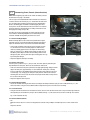
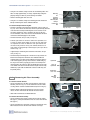
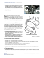
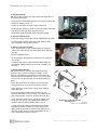
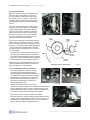
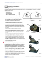
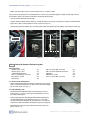
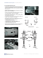
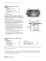
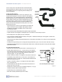
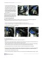
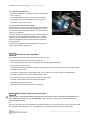
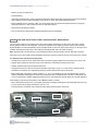
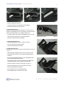
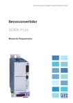
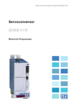
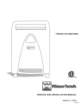
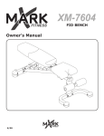
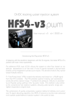
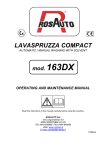
Installation Manual
Volvo S60R Front Mount
Intercooler System
Volvo S60R Intercooler System / Installation Manual
C
Contents
Important Information
1
Parts List
1
Required Tools and Materials
2
1.0
Vehicle Preparation
2
2.0
Removing Front Fascia (Nose Section)
3
3.0
Removing Bumper Reinforcing Bar
4
4.0
Removing Air Filter Assembly
5
5.0
Removing Factory Intercoolers and Tubes
6
6.0
Drilling, Trimming and Misc.
9
7.0
Installing New Intercooler
10
8.0
Installing New Intercooler Tubes
12
9.0
Reinstalling Bumper Reinforcing Bar and Spacers
12
10.0 Reinstalling Air Filter Assembly
15
11.0
15
Start Engine and Check Connections
12.0 Trim and Install Front Fascia (Nose Section) Substructure
16
13.0 Trim and Install Front Fascia (Nose Section)
20
14.0 Test Drive
22
!
Important Information
Congratulations on your purchase of the Bell Intercoolers Volvo S60R Front Mount Intercooler System. The installation instructions in this manual will assist you in the complete process of installing your new intercooler. Please read through these instructions entirely before you begin the installation process. This will familiarize you with the process and alert you to any unique tools
or m
please do not hesitate to contact us at 210-412-0917.
however, it is important to honestly evaluate your mechanical skills and determine if you are capable of performing the installation
or if you should have the system installed by a professional mechanic. To help you identify possible difficulties, we have marked
steps of installation that are complex, require special tools or involve special procedures with this icon: !
A modern internal combustion engine is a precise piece of equipment and while durable they can be severely damaged or destroyed through careless installation techniques.
To
problems with the engine or vehicle corrected prior to installing the intercooler.
Bell Intercoolers, inc. © 2009 All rights reserved. S601-S60R-IMv3
Volvo S60R Intercooler System / Installation Manual
1
Parts List
Part Name
Packet/Box
Qty
Part Number
Intercooler Assembly
Intercooler
1
A3001361806070(B)
Intercooler Mounting Spacer
Parts - Bag 1
2
PLV6070-12
M10-1.25 x 80mm Bolt - Hex Head
Parts - Bag 1
2
P00700-M10-80-Z
M10 Washer
Parts - Bag 1
4
P00740-M10-C
M10-1.25 Hex Nut (Mechanical Locknut)
Parts - Bag 1
2
P00710-M10-15-Z
Intercooler Inlet Tube
Components
1
PLV6070-01-B
Intercooler Outlet Tube
Components
1
PLV6070-02-B
Throttle Inlet Tube
Components
1
PLV6070-03-B
Straight (2.5” ID x 3.0” L)
Hoses
1
P00503-0300BLAC
Straight Bellows Type (2.5” ID x 3.0” L)
Hoses
2
P00553-0300BLAC
Straight (3.0” ID x 2.5” L)
Hoses
1
P00505-0300BLAC
Intercooler Mounting
Intercooler Tubes
Silicone Hose
Reducer (2.0” or 2.25” to 2.5” ID x 3.0” L)
Hoses
1
P00562-250200B or P00561-250225B
Components
1
00760
2.25” or 2.0” (Hose ID)
Hose Clamps
1
P00600-002 or P00607-002
2.5” (Hose ID)
Hose Clamps
7
P00603-002
3.0” (Hose ID)
Hose Clamps
2
P00609-002
Horn Bracket - Left
Parts - Bag 2
1
PLV6070-05
Horn Bracket - Right
Parts - Bag 2
1
PLV6070-06
M6-1.0 x 20mm Bolt - Hex Head
Parts - Bag 2
2
P00700-M6-20-Z
M6-1.0 Hex Nut (Mechanical Locknut)
Parts - Bag 2
2
P00710-M6-1.0-Z
M6 Washer
Parts - Bag 2
4
P00740-M6-C
Radiator/AC Condenser Spacer
Parts - Bag 3
4
PLV6070-08
M6-1.0 x 40mm Bolt - Hex Head
Parts - Bag 3
4
P00700-M6-40-Z
M6 Washer
Parts - Bag 3
5
P00740-M6-C
M6-1.0 x 20mm Bolt - Hex Head (IAT Sensor)
Parts - Bag 3
1
P00700-M6-20-Z
Bumper Spacer - Outer
Parts - Bag 4
2
PLV6070-14
Bumper Spacer - Inner
Parts - Bag 4
2
PLV6070-15
Radiator Bulkhead Spacer
Parts - Bag 4
4
PLV6070-13
M10-1.5 x 60mm Bolt - Hex Head
Parts - Bag 5
2
P00700-M10-60-Z
M10 Washer - Canted
Parts - Bag 5
4
P00741-M10-CANT
M8-1.25 x 40mm Bolt - Hex Head
Parts - Bag 5
6
P00700-M8-40-Z
Poly Wire Loom - .75” Dia. x 14” L
Hose Clamps - T-Bolt Style
Horn Brackets and Fasteners
Radiator/AC Condenser Spacer and Fasteners
Bumper Bar Spacers and Fasteners
M8-1.25 Hex Nut (Mechanical Locknut)
Parts - Bag 5
6
P00710-M8-1.25
M8 Washer
Parts - Bag 5
8
P00740-M8-C
M8 Washer - Canted
Parts - Bag 5
4
P00741-M8-CANT
M10-1.5 x 45mm Bolt - Hex Head
Parts - Bag 5
2
P00700-M10-45-Z
M10 Washer
Parts - Bag 5
4
P00740-M10-C
Bell Intercoolers, inc. © 2009 All rights reserved. S601-S60R-IMv3
Volvo S60R Intercooler System / Installation Manual
2
Required Tools and Materials
To effici
supplied with your intercooler.
Tools
• 1/4” Drive Ratchet
• 1/4” Drive Extensions - 3” and 6” Length
• 3/8” Drive Ratchet
• 3/8” Drive Extension - 3” Length
• Sockets 8-17mm (1/4” or 3/8” Drive)
• 11 mm Deep Socket
• Wrench (Open/Boxed) 8-17mm
• T-25 and T-15 Torx Bits
• Flat-head Screwdriver
• Phillips Screwdriver
• Electric Handheld Drill (capable of holding .5” bit)
• Drain Pan for Engine Coolant
• .457” Drill Bit (or next larger size available)
• .312-.328” Drill Bit (or next larger size available)
• Vise-Grip style locking pliers (2 required)
• Small Trim/Molding Removal Tool (or Butter Knife)
• Hacksaw or Cutting Wheel
• Round and Flat File
• Ruler – 12” or longer
• Vehicle Jack or Lift
• Jack Stands (x2)
• Carpet Knife (Optional)
* Butane or Propane Torch (Optional)
Materials
• Grease Pencil or China Marker (non-permanent)
• Black Ink Marker Pen (Sharpie™)
• Satin Black Touch Up Paint
• Masking Tape
• Sandpaper - 600 Grit
1.0
Vehicle Preparations
As with any vehicle modification project, the process will be easier, faster and safer for the engine, turbocharger and you if the engine compartment is thoroughly cleaned before you begin the project. Not only is a dirty engine compartment a mess to work in, but
a dirty engine compartment also offers the possibility that dirt and/or debris could be introduced into the intake tract of the engine.
A small stone or piece of debris falling into an open turbo inlet can cause serious and expensive damage to the turbo when the
engine is started. Even worse, the debris could cause a turbocharger compressor failure leading to pieces of compressor blades
feeding into the cylinder, possibly damaging valves, cylinders and pistons. An easily avoidable, but expensive proposition.
Wh
all tubes, hoses and the intercooler for any foreign objects or debris before installing.
1.1 Disconnect Battery
Before beginning any work on this installation disconnect the negative terminal of the battery. During the installation you will have
ba
your Volvo service manual for details and procedures on disconnecting the trunk mounted battery.
1.2 Jack Stands or Lift
Installation of this intercooler system requires placing the vehicle on a lift or jack stands. Please consult Volvo service manual
proper jack, jackstand and/or lift placement. Be sure vehicle is securely positioned before proceeding.
Bell Intercoolers, inc. © 2009 All rights reserved. S601-S60R-IMv3
Volvo S60R Intercooler System / Installation Manual
2.0
3
Removing Front Fascia (Nose Section)
Note: Before beginning any work on the vehicle the battery must be
disconnected. See page 1 for details.
The first step in the installation will involve removal of the front nose
section or fascia of the vehicle (Fig. 2.1). Attached to the front fascia
are: the upper grill assembly, the front license plate and mounting
bracket, the driving light assemblies and driving light grills. All of
these pieces remain attached to the front fascia when it is removed
and only require that you disconnect one wiring connector for each
driving light assembly, one per side.
To reduce the chance of damaging the vehicle paint on the front
fascia and the surrounding bodywork, we recommend you have
someone available to help when you remove the fascia.
Trim Piece
T25 Torx
Location
Bolt Location
(under trim)
Figure 2.1
2.1 Remove Headlight Wipers
Before removing wipers make a note of the position of the wipers
(direction of arms) so you will reinstall them properly. Next fold the
wiper arm forward to access and remove the washer fluid tubing.
• Using small screwdriver, flip up cover at base of wiper arm (Fig.
2.2). Remove the 8 mm nut securing wiper arm. With the nut
removed, carefully grip the base of the wiper arm with locking
pliers as shown (Fig. 2.3). While gently rocking the wiper arm up
and down, pull the wiper arm off of the shaft being careful to not
damage the paint. You may want to wrap the locking pliers in a rag
to prevent paint damage.
Figure 2.2
Figure 2.3
• Repeat for opposite side wiper assembly.
2.2 Remove Trim Pieces
Two trim pieces (shown in Fig. 2.1), one per side, are held in place by tabs along the
top and bottom of each piece, which are inserted into the front fascia.
• Start at the front of the trim piece (end closest to upper grill opening). Along the lower
edge of the trim piece, approximately 1.5” from front/inner end of piece, carefully
insert the edge of the trim/molding removal tool (or butter knife) under the trim piece
as shown (Fig. 2.4). Gently pry the trim piece away from the front fascia to release
mounting tab. Once the first tabs has been released you will be able to easily release
the rest of the tabs by hand.
• Repeat for opposite side trim piece.
Figure 2.4
2.3 Remove Mounting Bolts
• Locate the two bolts securing the front fascia assembly to the bumper subframe (one per side as indicated in Fig. 2.1). Remove these bolts, using care not to allow the bolts to drop into the space in the front fascia assembly.
2.4 Loosen Retainers
• Using the T25 Torx bit, loosen the two retainer fasteners, one on each side of the front fascia. They are located just inside the
wheel opening on the fender liner (one per side as indicated in Fig. 2.1) and secure the fascia with a small clip. The fastener
Fig. 2.5 for a detail of this clip.
2.5 Remove Bulkhead Rivets
• Loc
bulkhead. Please note, these rivets are designed to be reused. Using a Phillips screwdriver press the center section of the
ri
Repeat for all rivets.
Bell Intercoolers, inc. © 2009 All rights reserved. S601-S60R-IMv3
Volvo S60R Intercooler System / Installation Manual
2.6 Remove Front Fascia
Note: This process can be accomplished by a single person if you know
what to expect and proceed carefully. That said, it is much easier and
safer for the paint work if you have an assistant.
• Grasping the rear edge of the front fascia (at the wheel opening), gently
pull the fascia out, to the side, approximately .5”, to clear side clips, and
move fascia forward about two inches. Repeat for other side.
4
Securing
Clip
T25
Torx
Fascia
Rear
Edge
• With the front fascia pulled forward slightly you will need to disconnect
the two wiring connectors for the driving lights (one per side). These
are located on the inside of the front fascia, above the left and right side
driving light assemblies. Disconnect both harnesses.
• You may now completely remove the front fascia.
2.7 Remove Underbody Tray
Located underneath the radiator / AC condenser / intercooler assembly is
the underbody tray. It is secured by two bolts (one per side) and two tabs
(one per side). Locate the two tabs on the lower edge of the bumper cross
member, release the tabs and slide them out of their slots. Locate and
remove the two bolts, found at the outer rear corners of the underbody tray.
Figure 2.5
The underbody tray may now be removed.
3.0
Removing Bumper Reinforcing Bar
Note: The installation of the bumper reinforcing bar spacers is not a permanent modification to the vehicle and the bumper reinforcing bar can be returned to it’s original position with the use of Volvo standard replacement parts.
The bumper reinforcing bar is the large, aluminum cross bar shown in Figure. 3.1. For installation of the intercooler system you will
be placing spacers between the bumper reinforcing bar and the main vehicle frame. These spacers move the bumper reinforcing
bar forward to allow space for the intercooler.
To remove the bumper reinforcing bar you will remove four bolts (two per
side) and drill out six spot welds (three per side). These bolts and spot
welds are attached to the bumper reinforcing bar via replaceable steel
pads available from Volvo. The spots welds, once drilled out, are replaced
with high strength bolts and the spacers are CNC machined from 6061-T6
aluminum for strength and precision.
Drilling out the spot welds is easily accomplished with a .420” drill bit,
though it is important to start the drill bit in the center of the spot weld to
ensure the weld is completely removed.
Bumper
Reinforcing Bar
Prior to removing the bumper reinforcing bar you will need to drill out the
mounting holes for the new intercooler and radiator bulkhead spacers.
Figure 3.1
3.1 Enlarge Intercooler Mounting Bracket Holes
The intercooler mounts to the bumper reinforcing bar
and radiator bulkhead with two bolts and spacers. In
addition to the bolts and spacers for the intercooler
• Locate the mounting hole to be used for new
intercooler mounting brackets. These are located
on either side of the upper grill opening and are attached to a flange at the back of the bumper cross
member (as shown in Figures 3.2, 3.3 and 3.4).
Mounting Pin
and Hole
Left Side
Figure 3.2
Mounting
Pin
Left Side - Detail
Mounting
Hole
Figure 3.3
Bell Intercoolers, inc. © 2009 All rights reserved. S601-S60R-IMv3
Volvo S60R Intercooler System / Installation Manual
• Using the .420” drill bit, enlarge each of the two mounting holes. The
holes are only approximately .25” deep, only drill deep enough to
properly enlarge the holes to prevent damage to radiator.
• Remove mounting pins from each side.
• Using the .312” drill bit, enlarge the mounting pin holes in both the
bumper reinforcing bar and the radiator bulkhead.
3.2 Remove Bumper Reinforcing Bar
• Remove secondary nuts from back of outer bolts, one per side (see
Fig. 3.5). These are not the main nuts which are permanently attached
to the back of the bumper reinforcing bar, but are used to secure
electronic components (these secondary nuts may not be present on all models). These nuts must be removed before the bolt is
removed to avoid damaging the nut and bolt.
5
Mounting
Pin
Radiator
Bulkhead
Mounting Bolt
Bumper
Reinforcing
Bar
Right Side Detail
Inner
Mounting
Bolt
Figure 3.4
Outer
Mounting
Bolt
• Remove outer bolts, one per side (see Fig. 3.5).
• Drill out spot welds. To center the drill on the spot welds, use
a punch or similar tool to indent the center of each spot weld.
It is important to center the drill bit in each spot weld so that
the weld is fully removed. Using .420” drill bit drill out the six
spots welds securing bumper reinforcing bar (three per side as
shown in Fig. 3.5).
Inner
Spot Weld
• Support bumper reinforcing bar and remove inner bolts, one per
side (see Fig. 3.5).
• Remove bumper reinforcing bar. It will be necessary to rotate the
bottom of the bumper bar forward to clear radiator bulkhead
mounting point. If bar does not immediately come loose from the
main frame supports you may need to insert a suitable tool (pry
bar, large screw driver) to gently pry it loose. If the bumper reinforcing bar does not come free with reasonable force check to be
sure all bolts have been removed and that all spot welds are fully
drilled out (if spot welds are drilled off center the welds may still
be partially intact).
4.0
Removing Air Filter Assembly
Outer
Spot Welds
(x2)
Figure 3.5
Spot Weld
Center of
Spot Weld
Replacable
Steel Pad
Bolt
Mounting
Hole
Figure 3.6
4.1 Remove Cold Air Snorkel
• Locate and remove the two bolts securing cold air snorkel to air
filter box (Items A in Fig 4.1). Locate and remove the three bolts
securing cold air snorkel to radiator bulkhead (Items B in Fig 4.1).
Cold Air
Snorkel
Air Inlet
Tube
• Remove cold air snorkel from air filter box, you may need to
release the two small raised tabs located next to the A bolts.
• Slide cold air snorkel out of radiator bulkhead.
4.2 Remove Air Filter Assembly
• Locate and loosen hose clamp securing air inlet tube to air filter
box (Fig 4.2). Unclip and disconnect mass air sensor from air filter
box (Fig 4.2).
• Locate and remove the three bolts securing the air filter box. Two
bolts located to the left side of the box and one to the right.
A
B
Air Filter Box
Figure 4.1
Bell Intercoolers, inc. © 2009 All rights reserved. S601-S60R-IMv3
Volvo S60R Intercooler System / Installation Manual
• The air filter box is now ready to be removed. Lift the front of the
air filter box and remove air filter box from air inlet tube. Once
clear of the air inlet tube, lift air filter box and disconnect vacuum
line bundle, located on the driver’s side of the air filter box. This
bundle of vacuum lines is secured to air filter box with a tab and it
can pulled off.
6
Air Inlet
Tube
Hose
Clamp
Mass Air
Sensor
• Remove air filter box.
Figure 4.2
5.0
Removing Factory Intercoolers
Inlet
Hose
Note: For this step of the installation process it will be necessary to
drain the engine coolant. At this point you may wish to replace your
engine coolant, as well as radiator hoses. We recommend replacing
hoses if they have been in use for more than two years or 20,000
miles, as they can become less flexible and prone to cracking and
failure when handled.
Outlet
Tube
The S60R utilizes two intercoolers, a large primary intercooler and
a small secondary intercooler, in the factory intercooler system.
The primary intercooler is secured between the AC condenser and
radiator to form an assembly which is then attached to the radiator
bulkhead. To remove the primary intercooler you must detach the
AC condenser and primary intercooler from the radiator. The radiator
and AC condenser will be lowered to extract the primary intercooler.
The AC system does NOT need to be evacuated form this process,
though care must be exercised when working with the various AC
lines and components to prevent damage.
5.1 Remove Secondary Intercooler
• Locate the secondary intercooler connection hoses on each end
of the secondary intercooler. Loosen all hose clamps (x4) for the
left and right connection hoses.
Vacuum/
Boost
Port
Primary
Intercooler
IAT
Sensor
A
Secondary
Intercooler
A
• Locate and remove the two mounting bolts securing the secondary intercooler to the AC condenser (see Items A in Fig. 5.1).
Factory Intercoolers, Tubes and Hoses
Figure 5.1
• Remove secondary intercooler and intercooler connection hoses.
Illustration / Volvo Cars North America
5.2 Remove Intercooler Inlet Hose and Outlet Tube
• Locate intercooler inlet hose (see Fig. 5.1).
• Loosen hose clamp securing intercooler inlet hose to intercooler.
• Loosen hose clamp securing intercooler inlet hose to the over-engine-pipe (OEP, the large tube running over top of engine
from front to rear). Remove intercooler inlet hose.
• Locate vacuum/boost port on intercooler outlet tube (see Fig. 5.1). Remove hose from port.
• Locate and loosen hose clamp securing intercooler outlet tube to intercooler.
• Locate hose clamp securing intercooler outlet tube to underside of engine intake manifold. Loosen hose clamp and remove
tube.
5.3 Remove IAT Sensor Harness
• Locate the intake air temperature (IAT) sensor, located on intercooler outlet (see Fig. 5.1). Disconnect wiring harness from IAT
sensor. Locate and remove bolt securing IAT sensor to intercooler (T15 Torx bit). Carefully remove IAT sensor being sure not to
damage O-ring seal.
Bell Intercoolers, inc. © 2009 All rights reserved. S601-S60R-IMv3
Volvo S60R Intercooler System / Installation Manual
7
5.4 Drain Engine Coolant
Note: You may wish to replace your engine coolant and radiator hoses as
part of routine maintenance.
• Locate the plastic radiator drain plug/nozzle at the lower right (driver side)
corner of the radiator (see Fig. 5.2).
• Remove cap from coolant reservoir in engine compartment.
• Position drain pan and loosen, but do not remove drain plug. Coolant will
drain without the drain plug being completely removed.
• When coolant completely drained, retighten coolant drain plug.
5.5 Disconnect Radiator Hoses
• Loosen hose clamps securing upper and lower radiator hoses to radiator.
Coolant
Drain Plug
Figure 5.2
• Disconnect upper and lower radiator hoses from radiator. Remove
hoses completely if replacing with new hoses.
5.6 Remove Cooling Fan Assembly
• Locate and remove two (2) bolts securing cooling fan assembly to
radiator. These will be located at the upper corners of the cooling fan
assembly.
• Disconnect fan wiring harness.
• Lift fan assembly to disengage two (2) mounting tabs near bottom of
fan assembly.
• Carefully lift cooling fan assembly from behind radiator, being sure
not to damage radiator cooling fins or core when extracting the fan
assembly.
Figure 5.3
5.7 Remove Primary Intercooler
Note: The AC condenser, intercooler and radiator are lowered
together (see Fig. 5.3) before removing the intercooler. The AC
condenser is not completely removed from the vehicle and the AC
lines are NOT disconnected during this process. Care must be given
to ensure the AC lines and connections are not damaged during this
process.
• Locate wiring connector on AC condenser, on passenger side,
attached to AC Dryer (silver canister). Disconnect connector.
• Locate and remove the two (2) bolts securing top of radiator to
radiator bulkhead.
A
B
Radiator
B
A
• Locate the four bolts connecting the AC condenser, primary
intercooler and radiator (see Items A in Fig. 5.4). Remove the two
upper connecting bolts. Remove the two lower connecting bolts.
• Locate and remove the two (2) bolts securing the radiator to the
vehicle (see Items B in Fig. 5.4). Carefully lower radiator, AC
condenser and intercooler into position shown in Fig. 5.3.
Radiator/AC Condenser/Intercooler
Mounting Points
Figure 5.4
Illustration / Volvo Cars North America
• Carefully separate AC condenser and radiator from intercooler
and remove intercooler. It will be necessary to extract the intercooler towards the top of the AC condenser and radiator due to
the various AC lines. Exercise care to avoid damaging AC condenser and radiator fins during this process.
Bell Intercoolers, inc. © 2009 All rights reserved. S601-S60R-IMv3
Volvo S60R Intercooler System / Installation Manual
8
5.8 Reposition AC Dryer
Note: This step may or may not be required for your
particular vehicle. S60R model years 2004-2005
use a larger AC dryer canister than the later 20062007 models (see Fig. 5.5 and 5.6). If your vehicle
is equipped with the smaller AC dryer canister you
will not need to perform this step and should skip to
Step 5.9.
This step in the installation process requires repositioning the AC dryer (see Figure 5.7) by bending the
AC dryer bracket slightly. This procedure does not
require any special tools, equipment or techniques.
However, the bracket to be bent is attached to the
AC condenser and care must be taken not to damage the AC condenser during the process. Do not
force AC lines during the removal process.
AC
Dryer
AC
Dryer
Early Style AC Dryer
New
Position
The AC dryer is attached to the AC condenser with an
aluminum bracket. This bracket is fairly easy to bend
into the new position by rotating the AC dryer as shown
in Figure 5.7. The AC dryer will be moved approximately
1” when rotated from it’s original position. The before
and after positions of the AC dryer can be seen in Figures 6.8a and 6.8b.
• Grip the AC dryer canister firmly with both hands or
with a large pair of channel lock pliers. Carefully rotate AC dryer canister, bending the bracket as shown
in Figure 5.7. Only the aluminum bracket should bend
within the bracket bend area indicated in Figure 5.7.
Figure 5.5
Late Style AC Dryer
Bracket
Bend
Area
Rotate
When the AC dryer is properly positioned Section A of
the bracket will be in line with the face of the AC condenser (see Figures 5.7, 5.8a and 5.8b).
5.9 Reassemble AC Condenser and Radiator
• Reassemble radiator / AC condenser assembly.
At each of the four connecting points position
supplied Radiator/AC Condenser Spacer between
the radiator and AC condenser and insert supplied
bolt and washer assembly into each corner of the
radiator /AC condenser assembly (see Figure 5.9,
Note: Spacer, normally black, is shown here in
silver for photographic clarity).
• On vehicles with larger AC dryer canister check
clearance of AC dryer to radiator. There should be no contact between
AC dryer and radiator, if there is contact, carefully rotate AC dryer to
provide additional clearance (see Step 5.7). There should be at least
1/8” between AC dryer canister and any part of the radiator.
Figure 5.6
AC
Condenser
Bracket
Section A
Original
Position
AC Dryer Positions - Bottom View
Original Position
Bottom View
Figure 5.7
New Position
Bottom View
Figure 5.8a
Figure 5.8b
Spacer
• Tighten four (4) bolts to secure AC condenser to radiator.
• Return AC condenser / radiator assembly to original position and reinstall two (2) bolts securing radiator to vehicle (see Items B in Fig. 5.4).
Do not tighten these bolts until after step 6.2. Do not reinstall two (2)
bolts securing top of radiator to radiator bulkhead.
Figure 5.9
Bell Intercoolers, inc. © 2009 All rights reserved. S601-S60R-IMv3
Volvo S60R Intercooler System / Installation Manual
6.0
9
Drilling, Trimming and Misc.
6.1 Installing Horn Brackets
Installation of the larger intercooler requires the use of new horn brackets. These brackets rotate the horns from their original vertical position in the upper grill opening to a horizontal position (see Fig. 6.1). The following brackets and fasteners are provided
with your intercooler system:
New Components
Horn Bracket - Left
Horn Bracket - Right
M6-1.0 x 20mm Bolt - Hex Head
M6-1.0 Hex Nut (Mechanical Locknut)
M6 Washer
(x1)
(x1)
(x2)
(x2)
(x4)
• Remove horns and original brackets. Locate and remove
bolts securing the twin horns in the upper grill opening.
Note orientation of horns. The horns are secured with
one bolt per horn. Disconnect wiring connector from each
horn. Remove horns and label as “Right” and “Left.”
Mounting
Point
Horn (Right)
Horn (Left)
Final Horn Position
Upper Grill Opening
(from front)
• Remove factory brackets from each horn. Secured with a
single bolt which will be used to attach the new horn brackets.
• The factory horns have a trumpet style shape and the opening of
that shape is in close proximity to the top of the new intercooler. This
proximity can reduce the effective volume level of the horns and we
recommend that you trim the horn trumpet slightly to allow for proper
horn volume.
Mounting
Point
Figure 6.1
Mounting Bolt
Bracket
(Left)
Horn
(Left)
Front
Referring to Figure 6.3, trim each horn using a hacksaw.
• Identify new left and right brackets and attach to horns as shown
in Figure 6.2 (Left side horn and bracket shown, reverse for right
side). Tighten bolts. Note: Left refers to passenger side, right to
driver side.
• Place horns into grill opening, behind power steering cooler and
install using the supplied nuts, bolts and washers. Note that the
horns are now rotated 90º from their original position. Figure 6.1
shows the horns in their new positions (power steering cooler not
shown) with mounting bolts for brackets facing up, rather than forward. Note position of wiring connectors, these should face forward.
Align horns and tighten.
• Attach wiring connectors to each horn.
!
6.2 Trim Radiator Bulkhead
Note: This step involves cutting and/or grinding to remove metal from
the upper radiator bulkhead. This material is removed the enlarge the
opening for the AC charging port. A hacksaw and file or a Dremel tool
with cutting wheel and grinder will accomplish the job with little difficulty. However, if you are not comfortable with tackling this job yourself,
any good paint and bodyshop will be able to do this for you.
• Locate AC charging port opening in radiator bulkhead. It is located
just above the left edge of the upper grill opening, as shown in
Figure 6.3 and Figure 6.4b (detail).
Wiring
Connection
Left Horn/Bracket
Assembly
Figure 6.2
Trim
Line
Trimmed
• Using a grease pencil draw a line straight back from the edge of the
existing hole in the radiator bulkhead (Items A in Figure 6.4b).
• Draw a line across, connecting the two previous lines, 3 inches from
the bottom of the opening (Item B in Figure 6.4b).
Figure 6.3
Bell Intercoolers, inc. © 2009 All rights reserved. S601-S60R-IMv3
Volvo S60R Intercooler System / Installation Manual
10
• Radius each of the upper corners as shown in Figure 6.4b. A .5” radius is shown.
Using a hacksaw or cutting tool, cut carefully along lines. Exercise care to avoid damaging the radiator. Smooth edges with flat
and round files. Figure 6.4c shows the finished AC charging port opening shape.
• Coat any exposed metal with touch-up paint.
• Properly reposition radiator and AC condenser assembly and tighten two (2) bolts securing top of radiator to radiator bulkhead.
• Tighten two (2) bolts securing radiator to vehicle (see Items B in Fig. 5.4).
• Reinstall upper and lower radiator hoses and refill engine coolant with specified type and quantity. Close coolant reservoir cap.
3”
AC Charging
Port
B
A
Figure 6.3
7.0
A
Figure 6.4a
Figure 6.4b
Figure 6.4c
Reinstall Bumper Reinforcing Bar
New Components
Bumper Spacer - Outer
Bumper Spacer - Inner
Radiator Bulkhead Spacer
M10-1.5 x 60mm Bolt - Hex Head
M10 Washer - Canted
M10 Washer
(x2)
(x2)
(x4)
(x2)
(x4)
(x4)
M8-1.25 x 40mm Bolt - Hex Head
M8-1.25 Hex Nut (Mechanical Locknut)
M8 Washer
M8 Washer - Canted
M10-1.5 x 45mm Bolt - Hex Head
7.1 Remove Plastic Backing Plate
• Remove plastic backing plate from bumper reinforcing bar. This backing
plate is secured with two plastic rivets which can be removed by tapping
out the center section. (see Fig. 7.1).
(x6)
(x6)
(x8)
(x4)
(x2)
Bumper
Reinforcing
Bar
(back)
7.2 Adjust Mounting Tabs
• Locate inboard and outboard bumper bar mounting tabs on vehicle
frame (see Fig. 7.2). These are the large mounting points that secure
the bumper reinforcing bar.
Plastic Backing
Plate
• Using vise-grip type pliers gently bend the outboard tabs forward so they
are aligned with front face of AC condenser (see Fig. 7.3). These tabs
are easy to bend and the bend does not need to be exact, as the tabs will
conform to the angle of the bumper reinforcing bar spacers when tightened.
Figure 7.1
• Bend inboard tabs back so they are parallel with front face of AC condenser (see Fig. 7.3).
Bell Intercoolers, inc. © 2009 All rights reserved. S601-S60R-IMv3
Volvo S60R Intercooler System / Installation Manual
11
7.3 Reinstall Bumper Reinforcing Bar
• Position bumper reinforcing bar and install using inner bumper spacers (one per side) and fasteners (see in Fig. 7.4). Do not tighten. If
bolt does not align with hole you may need to adjust frame mounting
tabs (see Fig. 7.3)
Mounting
Tabs
• Position and install outer bumper spacers and fasteners as shown in
figures 7.4 and 7.7. Do not tighten.
• Position and install outboard radiator bulkhead spacers and fasteners as shown in figures 7.4 and 7.6. Do not tighten.
• Using intercooler mounting bolts (M10-1.25x80) as guides, position
inboard radiator bulkhead spacers.
• Install outboard radiator bulkhead spacers and fasteners (M8-1.25 x
40 bolts, washers and locknuts). Do not tighten.
• Tighten bumper reinforcing bar and radiator bulkhead fasteners in
the following sequence (see Figs. 7.4 and 7.5):
1) Inner bumper bolts (one per side)
2) Outer bumper bolts - Center (three per side)
3) Outer bumper bolts - Upper and Lower (two per side)
4) Radiator bulkhead bolts (one per side)
Figure 7.2
Outer Tab
Inner Tab
Original
Position
New
Position
Front
• Remove intercooler mounting bolts that were used as guides from
radiator bulkhead mounting point, leaving spacers in place.
New
Position
Original
Position
Mounting Tab Bend
Figure 7.3
M10-1.5 x 45
M8-1.25 x 40
Mounting Tabs
(Frame)
M10-1.5 x 60
M8-1.25 x 40
Inner
Spacer
Inner
Outer
Spacer
Outer
Bumper
Reinforcing
Bar
Figure 7.4
Grill
Opening
Canted
Washers
Headlight
M10-1.25 x 80
Front
Inner
Mounting
Point
M8-1.25 x 40
Outer
Mounting
Point
Radiator Bulkhead Mounting Tab Detail
Inner Spacer
Top View
Figure 7.6
Outer Spacer
Top View
Figure 7.7
Figure 7.5
Bell Intercoolers, inc. © 2009 All rights reserved. S601-S60R-IMv3
Volvo S60R Intercooler System / Installation Manual
8.0
12
Installing New Intercooler
New Components
AC Condenser / Radiator Spacer
Intercooler
M10-1.25 x 80mm Bolt - Hex Head
Intercooler Spacer
M10-1.25 Hex Nut (Mechanical Locknut)
M10 Washer
8.1 Install New Intercooler
The new Intercooler will be installed with the mounting brackets
facing forward. When the Intercooler and Intercooler Spacers are
installed properly there will be approximately a .5” gap between the
Intercooler face and the AC condenser face. The Intercooler should
be parallel to the AC condenser.
Pay special attention to the position of the intercooler spacers.
Each of the two spacers has an angled face and must be installed
with the wide section of the spacer facing down (see Figure 8.2). If
these intercooler spacers are not correctly positioned the intercooler will not align with the AC condenser face.
• Move intercooler into position in front of AC condenser. Be careful not to damage cooling fins on Intercooler or AC condenser.
• Install mounting fasteners and spacers through as shown in
Figure 8.2. Be sure spacers are rotated as shown, with widest
section to the bottom, to ensure proper spacing between the
intercooler and AC condenser.
• Align bottom edge of Intercooler to bottom edge of radiator / AC
condenser Assembly and tighten mounting fasteners.
Bracket
Bracket
(x4)
(x1)
(x2)
(x2)
(x2)
(x4)
Outlet
Inlet
Intercooler - Front View
Figure 8.1
Radiator
Bulkhead
Intercooler
Bracket
Radiator Bulkhead
Spacer
Intercooler
Spacer
Bumper
Cross Member
Bracket and Fastener Diagram
Figure 8.2
• Check for proper alignment and spacing between intercooler
and AC condenser (approximately .5”) and parallel mounting to
the AC condenser.
9.0
Installing New Intercooler Tubes
New Components
Intercooler Inlet Tube
Intercooler Outlet Tube
Throttle Inlet Tube
Hose Clamp (T-Bolt) - 2.0” or 2.25”
Hose Clamp (T-Bolt) - 2.5”
Hose Clamp (T-Bolt) - 3.0”
(x1)
(x1)
(x1)
(x1)
(x7)
(x2)
Poly Wire Loom
Silicone Hose - Straight 2.5” Dia.
Silicone Hose - Straight 3.0” Dia.
Silicone Hose - Bellows 2.5” Dia.
Silicone Hose - Reducer 2.0” or 2.25” - 2.5” Dia.
(x1)
(x1)
(x1)
(x2)
(x1)
Note: To ensure the intercooler tubes are securely installed you will need to properly position the silicone hose and hose clamps
in
f
of the tube under high boost pressure.
Fo
er tubes mark all tubes with a line 1” in from the bead. This will allow you be sure the clamp and hose are properly positioned.
-
Hose clamps should be tightened to the point where the silicone hose cannot be rotated against the metal tube. Overtightening
can result in cutting and damaging the silicone hose.
Bell Intercoolers, inc. © 2009 All rights reserved. S601-S60R-IMv3
Volvo S60R Intercooler System / Installation Manual
13
The hose clamps for the intercooler inlet tube and intercooler outlet
tube may positioned as shown in Figures 9.3a, 9.3b, 9.4a, 9.4b and
9.4c to allow for easy access for tightening while not rubbing on the
front fascia bodywork.
9.1 Relocate Wiring Harness
To avoid damage to wiring harness due to close proximity to accessory drive belt and pulley it is necessary to relocate a short portion of
the wiring harness. This section of wiring harness is located behind
radiator and lower left corner of radiator and runs between the engine
and the radiator. To relocate this section you will disconnect the tabs
securing the harness, wrap the harness in a poly wire loom (provided
with system) and relocate the harness closer to the radiator. Care
must be exercised when working with the wiring harness so as not to
damage any of the wires.
Intercooler
Inlet Tube
Intercooler
Outlet Tube
Throttle
Inlet Tube
• Locate wiring harness. Harness is located between the radiator and
engine near lower left corner of radiator. Note position of harness
in relation to crossmember and radiator. Harness will be moved
forward towards radiator.
Figure 9.1
• Locate and remove bolt securing wiring harness guide to engine crossmember.
• Separate two halves of wiring guide. Carefully clip zip ties as needed so as not to damage any wires.
• Extract wiring harness from guide to just past securing bolt.
• Using a hacksaw or suitable cutting tool carefully cut wire guide .5” outboard of mounting tab securing guide. Cut both halves
of guide. Remove cut section of guide.
• Using electrical tape carefully wrap exposed wiring harness to keep loose wires bundles. Use tie wraps to secure taped bundle
every six inches.
• Carefully insert exposed wiring harness into poly wire loom (provided with system). Secure ends of wire loom with tie wraps.
• Reposition fully wrapped wiring harness forward towards radiator. Harness will be held away from accessory drive belt and pulley
by intercooler inlet tube.
9.2 Install Intercooler Inlet Tube
• Mark both ends of intercooler inlet tube with line 1” from bead (see Fig. 9.2).
• Position silicone reducer hose (2.25” - 2.5” dia.) and 2.25” hose clamp on
over-engine-pipe (tube running forward across top of engine). Position hose
clamp so it will not contact any surrounding components during engine
movement (approx. .25” gap). Tighten clamp.
• Position second hose clamp (2.5”) on opposite end of silicone reducer hose.
Intercooler
Tube
Retaining
Bead
Silicone
Hose
1”
Mark
Line
• Install bellows (hump) silicone hose (2.5” dia.) and 2.5” hose clamp on Intercooler inlet (see Figs. 9.3a and 9.3b). Position properly behind bead and
tighten hose clamp (see Fig. 9.2).
Hose
Clamp
• Position a second hose clamp (2.5”) on opposite end of silicone bellows
hose at Intercooler inlet.
• Install intercooler inlet tube. Both ends of tube will be inserted into the respective hoses at the same time.
Hose and Clamp Placement Diagram
Figure 9.2
• Position tube so it will not contact any surrounding components, a .25” gap
should be sufficient to allow for engine movement.
• Position wiring harness forward towards radiator.
• When tube is properly positioned, tighten hose clamps.
Bell Intercoolers, inc. © 2009 All rights reserved. S601-S60R-IMv3
Volvo S60R Intercooler System / Installation Manual
14
• On vehicles with small AC dryer canister
check for clearance issues with AC dryer line
and carefully adjust line position as needed.
• Carefully check for clearance issues with
wiring harness and adjust as needed. If the
harness is allowed to make contact with
the engine accessory drive belt or pulley it
will be damaged quickly and this damage
can be expensive.
Note: There is a small plastic tab located on
the back of the radiator assembly, for positioning the wiring harness, which may rub on
tube. If it does rub, carefully remove the tab
with a hacksaw and file rough edges.
Figure 9.3a
Figure 9.3b
9.3 Install Intercooler Outlet Tube
Note: Tube is equipped with a port to allow for installation of Aquamist water injection system. Remove port plug for use.
• Mark both ends of intercooler outlet tube with line 1” from bead, as shown in Figure 9.2.
•
tion hose and clamp properly behind retaining bead and tighten hose clamp (see Fig. 9.2).
• Position a second hose clamp (2.5”) on opposite end of silicone hose. Note position of clamp (see Fig. 9.4c).
• Install intercooler outlet tube. Do not tighten clamps.
Figure 9.4a
Figure 9.4b
Figure 9.4c
9.4 Install Throttle Inlet Tube
• Mark both ends of throttle inlet tube with line 1” from bead (see Figure 9.2).
• On la
hose extends past end of throttle inlet tube. You will need estimate position of hose clamp and test install onto throttle inlet to
determine final position. When final position is determined, tighten hose clamp.
• Position second hose clamp (3.0”) on silicone hose and install on throttle inlet. Be sure hose and clamp are seated squarely
against throttle inlet. Snug hose clamp to allow you to rotate hose into position with intercooler outlet tube.
• Install straight silicone hose (2.5” dia.) and hose clamp (2.5”) on other end of throttle inlet tube. Do not tighten.
•
tioning hose and clamps according to bead reference line. Position tubes with a minimum of .25” of clearance to all surrounding components. Check that silicone hose and hose clamp at throttle inlet are still squarely seated against throttle inlet.
• Tighten hose clamps, including throttle inlet clamp.
• Recheck clearance of both tubes, providing a minimum of .25” of clearance from all surrounding components. Adjust as needed.
Bell Intercoolers, inc. © 2009 All rights reserved. S601-S60R-IMv3
Volvo S60R Intercooler System / Installation Manual
15
9.5 Install Hoses and IAT Sensor
• Reinstall vacuum/boost hose, attaching to hose boss on throttle inlet
tube (see Fig. 9.5).
Vacuum/Boost
Hose
• Using supplied bolt and washer, reinstall IAT sensor attaching to
mounting boss on intercooler outlet tube as shown (see Fig. 9.5).
• Reconnect IAT sensor wiring harness.
9.6 Recheck Clearances and Hose Clamps
Before proceeding, recheck all tube clearances. Also recheck all hoses
and hose clamps to ensure they are properly positioned to the bead
reference lines and are properly tightened. Be sure to check both hose
clamps at the throttle inlet.
IAT Sensor
At this time also check for any wiring harnesses or other components
that may have come loose during the installation. This is especially
important in the area surrounding the engine drive belts as any loose
wiring or component that comes into contact with this belt could be
severely damaged.
Figure 9.5
15 minutes spent looking for potential problems now can prevent expensive and/or dangerous damage later.
10.0
Reinstall Air Filter Assembly
Reinstall air filter box in reverse sequence of removal (Section 3.0, pg. 4).
• Reattach vacuum line bundle to tab on side of air filter box.
• Insert air filter outlet into air inlet tube. This tube will snap in place when properly positioned.
• Reconnect mass air sensor harness.
• Install three bolts securing air filter box. Only tighten lower right bolt, leave others loose so air filter box can be shifted during
installation of cold air snorkel.
• Insert cold air snorkel into slot in radiator bulkhead. Be sure the snorkel fits over receiver within the radiator bulkhead.
• Install bolts securing cold air snorkel to radiator bulkhead. Tighten.
• Insert other end of cold air snorkel into air filter box. Be sure tabs engage.
• Install bolts securing cold air snorkel to air filter box and tighten.
• Tighten remaining two air filter box bolts.
• Tighten hose clamp connecting air filter box to air inlet tube.
11.0
!
Start Engine and Check Connections
NOTE: PRIOR TO STARTING ENGINE BE SURE RADIATOR HOSES ARE SECURELY REINSTALLED AND ENGINE COOLANT HAS BEEN REPLACED AND IS AT RECOMMENDED LEVEL. FAILURE TO REPLACE COOLANT CAN RESULT IN
SEVERE ENGINE DAMAGE.
Be
check the engine and make sure all components are functioning properly. The car will not be driven at this time, but this will allow
you to determine that all wiring harnesses, vacuum/boost lines, and intercooler tubes have been connected properly.
Bell Intercoolers, inc. © 2009 All rights reserved. S601-S60R-IMv3
Volvo S60R Intercooler System / Installation Manual
16
• Remove car from jack stands or lift.
• Reconnect battery.
• Start engine and allow engine to warm to operating temperature. Watch temperature gauge closely and check for function of
engine cooling fan. Shut off engine immediately if any gauges or engines lights indicate abnormal function.
• Engine should idle and rev normally. If it does not, shut off engine and check for loose intercooler tubes/hoses and disconnected wiring harnesses. Restart engine and check for normal idle and revs.
• Shut off engine and disconnect battery.
• Place car back on jack stands or lift to complete installation of front fascia bodywork.
12.0
Trim and Install Front Fascia (Nose Section) Substructure
This step requires relatively easy trimming of the plastic and styrofoam components of the front fascia substructure. All components being trimmed or cut are replaceable, no permanent components are modified, to allow the vehicle to be returned to
original condition if so desired. All trimming can be accomplished with a hacksaw or cutting wheel, however use of a band saw, if
available, will greatly speed the process. After cutting clean all rough edges with a file and/or sand paper.
Note: To protect paint of the front fascia it is recommended the work area be clean and the fascia be placed on a soft cloth.
Please note, the trim lines shown in these photographs will result in a proper fit, however you may wish to remove less material.
12.1 Remove Plastic Substructure and Styrofoam
• Carefully place the front fascia on suitable work surface and remove fog light support braces from front fascia. One per side.
• Separate plastic substructure from front fascia. Plastic substructure is attached by numerous plastic clips.
• Separate styrofoam impact strip from plastic substructure.
• Using grease pencil mark a line 5/8” from front of styrofoam impact strip (see Fig. 12.2). Front section of styrofoam will be
discarded. Do not damage rear section during cutting as it will be reattached to the plastic substructure.
• Mark and trim plastic substructure as shown in Figures 12.3 - 12.10. This trimming is not exact, but should be close to what is
shown in photographs to allow proper fit of front fascia. All trimming can be accomplished with a hacksaw or cutting wheel, however use of a band saw, if available, will greatly speed the process. After cutting clean all rough edges with a file and sand paper.
After trimming, test fit front fascia for proper fit. Trim additional material as needed.
• When satisfied with fit of front fascia, secure plastic substructure to bumper reinforcing bar using factory bolts that were used
to secure front fascia to bumper reinforcing bar. (see Fig. 12.1).
• Using masking tape, temporarily secure styrofoam impact grid in position to plastic substructure.
Mounting
Bolt
Styrofoam
Impact Strip
Plastic
Substructure
Mounting
Bolt
Plastic Substructure and Styrofoam Impact Strip
Figure 12.1
Bell Intercoolers, inc. © 2009 All rights reserved. S601-S60R-IMv3
Volvo S60R Intercooler System / Installation Manual
17
Trim Line
5/8” from Front Edge
Discard Front Section
Trim Line on Styrofoam Impact Strip
Figure 12.2
Plastic Substructure Trim Line Detail
Figure 12.3
Plastic Substructure After Trimming
Figure 12.4
Bell Intercoolers, inc. © 2009 All rights reserved. S601-S60R-IMv3
Volvo S60R Intercooler System / Installation Manual
18
Plastic Substructure Trim Line Detail
Figure 12.5
Plastic Substructure After Trimming (also showing styrofoam impact strip after trimming)
Figure 12.6
Plastic Substructure After Trimming
Figure 12.7
Bell Intercoolers, inc. © 2009 All rights reserved. S601-S60R-IMv3
Volvo S60R Intercooler System / Installation Manual
19
Plastic Substructure After Trimming
Figure 12.8
Plastic Substructure and Styrofoam Impact Strip After Trimming
Figure 12.9
Plastic Substructure After Trimming
Figure 12.10
Bell Intercoolers, inc. © 2009 All rights reserved. S601-S60R-IMv3
Volvo S60R Intercooler System / Installation Manual
13.0
!
20
Trim and Install Front Fascia (Nose Section)
This step requires relatively easy trimming of the plastic and urethane components of the front fascia and underbody tray. All trimming can be easily accomplished with a hacksaw or cutting wheel and cleaned up with a file and sand paper.
You may also use a heated carpet knife to trim some of the urethane components (lower grill opening and driving light area). This
method provides a very clean cut through the urethane and requires no additional finishing to the part. Please note, given the
This
fascia urethane.
13.1 Trim Lower Grill Opening
To provide adequate room for the new intercooler it is necessary to trim
the back of the lower grill opening (see Fig. 13.3). Volvo has provided a
convenient trimming line in the form of the edge of the painted surface
in this area (see Fig. 13.2a). You will be applying a strip of masking tape
along this paint line to protect the paint and provide a cutting guide.
Overlap tape onto unpainted surface by approximately 1/8”. This will
prevent you from cutting through the painted surface and will prevent
paint from chipping during the cutting process.
• Identify paint line on lower grill area (see Fig. 13.4a).
Area to be
removed
• Apply masking tape to the painted side of this line, covering painted
surface (see Fig. 13.4b).
• Using hacksaw, cutting wheel or heated knife, carefully cut along line.
Figure 13.3
• Clean up cut edge with file and sandpaper. The finished cut can be
seen in Figure 13.4c.
Paint Line
Figure 13.4a
Figure 13.4b
Figure 13.4c
13.2 Trim Left Driving Light Area
To provide space for the intercooler inlet tube it is necessary to trim a
portion of the front fascia in the area behind the left side (passenger
side for US/Canada market cars) as shown in Figures 13.5 and 13.6a.
• Using grease pencil draw cut lines on front fascia as shown in Figure
13.6b.
• Using hacksaw or cutting wheel, carefully cut along lines.
• Clean up cut edges with file and sandpaper.
• Finished cut can be seen in Figure 13.6c.
13.3 Trim Left Driving Light Grill Tab
• Remove driving light insert from left side front fascia (passenger side
for US/Canada market cars).
Area to be
Trimmed
Figure 13.5
Bell Intercoolers, inc. © 2009 All rights reserved. S601-S60R-IMv3
Volvo S60R Intercooler System / Installation Manual
21
Cut Lines
Figure 13.6a
Figure 13.6b
Figure 13.6c
• Identify tab indicated in Figure 13.7.
• Cut off tab and clean up cut edge with file and sandpaper.
• Reinstall driving light insert into front fascia.
13.4 Trim Underbody Tray
To provide space for the intercooler inlet tube it is necessary to trim a
portion of the underbody tray in the area behind the left side (passenger
side for US/Canada market cars) as shown in Figure 13.8a.
• Using grease pencil, draw cut lines on underbody tray (see Fig. 13.8b).
• Using hacksaw or cutting wheel, carefully cut along lines.
Tab to be
Removed
Driving Light Insert (Left)
Figure 13.7
• Clean up cut edges with file and sandpaper.
13.5 Reinstall Underbody Tray
• Reinstall underbody tray in reverse sequence of removal.
• Insert right side tab into slot below bumper.
• Secure rear mounting points with bolts.
13.6 Reinstall Front Fascia
Reinstall front fascia in reverse sequence of removal process (see Step
2.0, pg 3).
• Reinstall fog lights support brackets on front fascia (one per side).
• Position front fascia in front of car and connect driving light wiring
connectors.
Figure 13.8a
• Lift fascia and guide into position. Be sure to feed headlight washer
tubes through headlight wiper openings.
• The upper corners of the fascia, at the fender, must be guided into
small retaining grooves. Fascia should be flush with fender.
• Position rear edges of fascia on securing clips (see Fig. 2.5).
• Tighten securing clips at each rear edge (Torx T25 fastener).
• Install front mounting bolts and tighten.
• Install six plastic rivets across radiator bulkhead.
• Install headlight wipers and connect washer tubes.
Cut Line
Figure 13.8b
Bell Intercoolers, inc. © 2009 All rights reserved. S601-S60R-IMv3
Volvo S60R Intercooler System / Installation Manual
14.0
22
Test Drive and System Checks
Testing should be done with the radio and AC/heat fan off and with all windows rolled up to allow you to properly hear the engine.
Allow engine to reach operating temperature and make certain the engine is running smoothly and normally, both at idle and
under load, prior to applying boost.
• When the engine has cooled, check the area around the engine drive belts to be sure no wiring harnesses have worked loose
and come into contact with the engine drive belts.
• Recheck engine coolant level and fill as needed.
Installation is now complete.
It
position. This is also the time to check for any potential clearance issues.
Bell Intercoolers, inc. © 2009 All rights reserved. S601-S60R-IMv3