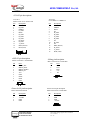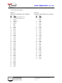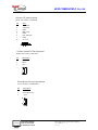
1
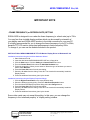
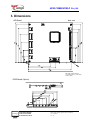
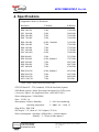
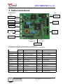
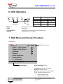
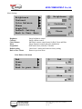
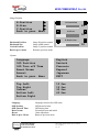
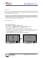
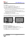
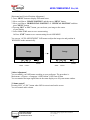
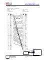
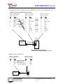
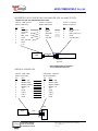
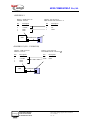
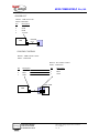
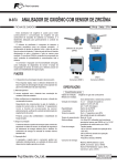
New om m NEW COMM WORLD Co.,Ltd. USER’S MANUAL (Preliminary) SOSA-AXG5 XGA TFT LCD Analog-Digital Conversion Board December. 1999 NEW COMM USA 4160B Technology Drive Fremont, CA 94538 Tel (510) 979-9950 Fax (510) 979-9973 artistage NEWCOMM WORLD TFTLCD MONITOR & BOARD SOLUTION SOSA-AXG5 Analog-Digital Conversion Board User’s manual, Ver. 1.0 1 New om m NEW COMM WORLD Co.,Ltd. 1. Product Overview artistage SOSA-AXG5TM, NEW COMM WORLD’s XGA TFT LCD Analog-Digital Conversion board (AD board), accepts standard analog RGB and SYNC signals from various VGA controller board currently available in the marketplace. SOSA-AXG5TM supports XGA and lower resolutions at vertical refresh rates up to 75Hz. Lower resolution modes can be expanded to the maximum screen size through expansion algorithm. The user interface includes PHASE, CONTRAST, BRIGHTNESS, HORIZONTAL and VERTICAL position adjustment and etc. Generally, the LCD based monitor emits less harmful rays, and does not require huge space. Moreover, the energy consumption of LCD monitor is remarkably little. Thus CRT monitors will be rapidly replaced by LCD monitors, and NEW COMM WORLD continuously provides best quality Analog-Digital Conversion board which conforms to various market requirements. 2. Compatibility •Connects directly to any standard CRT monitor output : D-SUB 15 pin connector (standard) Straight 13pin flat connector (option) •Supports IBM PC, Mac and NEC PC98 •Supports DPMS for monitor power management •Supports DDC1/2B •TFTLCD panels : XGA (1024x768 pixels) Samsung, Hyundai, LG and etc. •TFTLCD panel interface : TTL (standard) LVDS and PanelLink (option) artistage NEWCOMM WORLD TFTLCD MONITOR & BOARD SOLUTION SOSA-AXG5 Analog-Digital Conversion Board User’s manual, Ver. 1.0 2 New om m NEW COMM WORLD Co.,Ltd. IMPORTANT NOTE - FRAME FREQUENCY (or REFRESH RATE) SETTING SOSA-AXG5 is designed to run under the frame frequency (or refresh rate) up to 75Hz. You may free from invisible display problem which can be caused by mismatch of your display card and SOSA-AXG5 monitor in the initial connection to your new PC. It is highly recommended for you to change the frame frequency of your PC to 60Hz, because TFTLCD monitor shows best performance in frame frequency 60Hz. To change it, you can use the diskette included in the product. INSTALLATION of NEWCOMM WORLD TFTLCD Monitor Display Driver in Windows 95 / 98 Installation instructions using the Add New Hardware Wizard 1. Start Windows 95 or 98. 2. Insert the disk labeled NEWCOMM WORLD.INF into a floppy drive. 3. Click the Start button. Click the Setting and Control Panel menu item. 4. From the Control Panel folder select the Add New Hardware icon. 5. Follow the instructions. When you are asked to ’Select the type of hardware you want to install’ select Monitors. 6. Press the Have disk button from the next dialog. 7. Select the ‘A’ drive from the dialog. Press OK. The wizard will automatically install the Display Drivers. 8. Follow the additional instructions given by the wizard. Installation instructions using the Display Properties dialogs 1. Click the Right mouse button on the empty Desktop area. 2. Select the Settings property dialog. Press the Advanced Properties button. 3. From the Advanced Display Properties dialog select the Change buttons. 4. Press the Have disk button from the next dialog. 5. Select the ‘A’ drive from the dialog. Press OK. The wizard will automatically install the Display Drivers. 6. Follow the additional instructions given by the wizard. Some video cards may not accept this setting. In this case, you can change the frequency in the ‘advanced property’ of ‘display setting’ window. artistage NEWCOMM WORLD TFTLCD MONITOR & BOARD SOLUTION SOSA-AXG5 Analog-Digital Conversion Board User’s manual, Ver. 1.0 3 New om m NEW COMM WORLD Co.,Ltd. 3. Dimensions •AD Board Unit : mm Max height is used VGA I/F 2. If you used VGA I/F 1, max height is 12m/m.(Coil) •OSD Board (Option) artistage NEWCOMM WORLD TFTLCD MONITOR & BOARD SOLUTION SOSA-AXG5 Analog-Digital Conversion Board User’s manual, Ver. 1.0 4 New om m NEW COMM WORLD Co.,Ltd. 4. Specifications • Supportable Mode by Resolution Resolution V-Refresh H-Refresh IBM NEC IBM IBM 70 Hz 56 Hz 70 Hz 70 Hz 31.46 KHz 24.80 KHz 31.46 KHz 31.46 KHz IBM 640x480 IBM 640x480 IBM 640x480 NEC 640x480 MAC 640x480 60 Hz ; Standard 73 Hz 75 Hz 70 Hz 66 Hz 31.46 KHz 37.86 KHz 37.50 KHz 37.10 KHz 35.00 KHz IBM 800x600 IBM 800x600 IBM 800x600 IBM 800x600 NEC 800x600 56 Hz 60 Hz; Standard 72 Hz 75 Hz 70 Hz 35.15 KHz 37.87 KHz 48.07 KHz 46.87 KHz 47.80 KHz IBM 1024x768 IBM 1024x768 IBM 1024x768 NEC 1024x768 60 Hz; Standard 70 Hz 75 Hz 72 Hz 48.36 KHz 56.47 KHz 60.02 KHz 58.1 KHz 640x350 640x400 640x400 * 720x400 * * Note : Only 1 mode can be selected at once •TFTLCD Panel I/F : TTL (Standard), LVDS & PanelLink (Option) •OSD Board (option) : Menu, Decrement, Increment, Exit, LED, power • Accessory Option : See Application Note (APN-AXG5-001) •Power Management : VESA DPMS •Fuse : 12VDC, 3A •Environment : Relative Humidity 5 ~ 90% Non-condensing Operating temperature 5 ~ 40 C (41 ~ 104 F) •Plug & Play : DDC1/2B •DC Output : 12V (from AC / DC Adapter), 5V/0.6A •Power consumption : Operating :4.0Watt Max ( exclude adapter) Stand-by : 2.3 Watt (exclude adapter) artistage NEWCOMM WORLD TFTLCD MONITOR & BOARD SOLUTION SOSA-AXG5 Analog-Digital Conversion Board User’s manual, Ver. 1.0 5 New om m NEW COMM WORLD Co.,Ltd. 5. Cable Connections •AD Board I/F Option VOLUME Option Debug RS-232c port CONTROL LCD I/F VDD Sel. Panel VDD VOLUME CONTROL 1 Inverter CCFL (LCD) LCD I/F 1 ( TTL I/F) OSD OSD board LCD I/F Power In Power In +12VDC LCD I/F 2 ( TTL I/F) 2 Option Power Out 5V/12VDC VGA I/F2 (15 D-Sub. Female) (Option) VGA I/F1 (13pin, Straight) VGA Input * The Debug port can diagnostic AD board status to PC RS-232C port. (use debug cable and serial communication program (Ex. Hyper Terminal of Win 95/98)) Maker P/N Maker P/N VGA I/F 1 Molex 51014-1310 Molex 51004-1300 VGA I/F 2 Leoco DHSL-15(Female) Leoco DHPD-15(Male) LCD I/F 1 Hirose DF11-34DP-2DSA Hirose DF11-34DS-2C LCD I/F 2 Hirose DF11-26DP-2DSA Hirose DF11-26DS-2C Inverter Molex 53015-0810 Molex 51004-0800 Debug Molex 53015-0510 Molex 51004-0500 OSD Molex 53015-0910 Molex 51004-0900 Power In Molex 5268-04A Molex 5264-04 Power Out Molex 53015-0410 Molex 51004-0400 Volume Control Molex 51014-0310 Molex 51004-0300 Panel Power Leoco 2516P3T Leoco 3200SU00001 artistage NEWCOMM WORLD TFTLCD MONITOR & BOARD SOLUTION SOSA-AXG5 Analog-Digital Conversion Board User’s manual, Ver. 1.0 6 New om m NEW COMM WORLD Co.,Ltd. •OSD Board DOWN / DECREMENT MENU / SELECT Connector OSD artistage EXIT UP / INCREMENT OSD CONNECTOR DUAL COLOR LED Connectors on ADB Maker P/N Molex 53015-0910 NEWCOMM WORLD TFTLCD MONITOR & BOARD SOLUTION Counter Part Maker P/N Molex 51004-0900 SOSA-AXG5 Analog-Digital Conversion Board User’s manual, Ver. 1.0 7 New om m NEW COMM WORLD Co.,Ltd. •VGA IF pin descriptions VGA I/F 1 Molex 53014-1310 / 51004-1300 Pin Description 1 RED 2 R_GND 3 GREEN 4 G_GND 5 BLUE 6 B_GND 7 D_GND 8 D_GND 9 H_SYNC 10 D_GND 11 V_SYNC 12 DDA (DATA) 13 DCK (CLK) S vB VGA I/F 2 Leoco DHSL-15 / DHPD-15 SUBr e d Bu •OSD I/F pin description Molex 53015-0910 / 51004-09000 •Debug pin description Molex 53015-0510 / 51004-0500 Desc. MENU_SEL MENU_EXIT MENU_DOWN MENU_UP VCC GND LED2 LED1 GND Pin 1 2 3 4 5 6 7 8 9 S vBx Desc. TxD Gnd RxD +5V NC Pin 1 2 3 4 5 S Molex 5268-04A/5264-04 WBBr e d Bu Description +12VDC +12VDC GND GND •Power Out I/F pin description Molex 53015-0410 / 51004-0400 Pin 1 2 3 4 Description +5VDC GND GND +12VDC S artistage vBx [BBr e d Bu •Power In I/F pin description Pin 1 2 3 4 Description RED GREEN BLUE NC D_GND R_GND G_GND B_GND NC D_GND NC DDA (DATA) H_SYNC V_SYNC DCK (CLK) Pin 1 2 3 4 5 6 7 8 9 10 11 12 13 14 15 NEWCOMM WORLD TFTLCD MONITOR & BOARD SOLUTION vBx VBBr e d Bu SOSA-AXG5 Analog-Digital Conversion Board User’s manual, Ver. 1.0 8 New om m NEW COMM WORLD Co.,Ltd. •LCD I/F pin description LCD I/F 1 Hirose DF11-40DP-2DSA / DF11-40DS-2C Pin 1 2 3 4 5 6 7 8 9 10 11 12 13 14 15 16 17 18 19 20 21 22 23 24 25 26 27 28 29 30 31 32 33 34 35 36 37 38 39 40 artistage Desc. 5.0V Panel VVD(5V/3.3V) 5.0V Panel VVD(5V/3.3V) GND FSHCLK GND FFLM FLP FDE GND R-E0 R-E1 R-E2 R-E3 R-E4 R-E5 GND G-E0 G-E1 G-E2 G-E3 G-E4 G-E5 GND B-E0 B-E1 B-E2 B-E3 B-E4 B-E5 GND R-E6 R-E7 GND G-E6 G-E7 GND B-E6 B-E7 GND GND NEWCOMM WORLD TFTLCD MONITOR & BOARD SOLUTION LCD I/F 2 Hirose DF11-34DP-2DSA / DF11-34DS-2C Pin 1 2 3 4 5 6 7 8 9 10 11 12 13 14 15 16 17 18 19 20 21 22 23 24 25 26 27 28 29 30 31 32 33 34 Desc. GND R-O0 R-O1 R-O2 GND R-O3 R-O4 R-O5 GND G-O0 G-O1 G-O2 GND G-O3 G-O4 G-O5 GND B-O0 B-O1 B-O2 GND B-O3 B-O4 B-O5 GND R-O6 R-O7 GND G-O6 G-O7 GND B-O6 B-O7 GND SOSA-AXG5 Analog-Digital Conversion Board User’s manual, Ver. 1.0 9 New om m NEW COMM WORLD Co.,Ltd. •Inverter I/F pin description Molex 53015-0810 / 51004-0800 Desc. 12VSAFE 12VSAFE GND BRT_ADJ GND INV_ON/OFF GND 5V/3.3V Pin 1 2 3 4 5 6 7 8 S ZBBr e d Bu v Bx •Volume control I/F Pin description Molex 53014-0300 / 51004-0300 Pin 1 2 3 Description BIT1 BIT2 VCC BS BU vBx •Panel power select pin description Leoco 2516P3T / 3200SU00001 Pin 1 2 3 Description +3.3V Panel Power out +5.0V BS BU vBx artistage NEWCOMM WORLD TFTLCD MONITOR & BOARD SOLUTION SOSA-AXG5 Analog-Digital Conversion Board User’s manual, Ver. 1.0 10 New om m NEW COMM WORLD Co.,Ltd. 6. OSD (Example) MENU DOWN/DEC. UP/INC. EXIT MODE MENU EXIT ADJUSTMENT POWER POWER - Power off - No signal Red Always on Amber Blink Green Always on Suspend / Stand-by LED ADJUSTMENT LED Operation Power on Menu on/off. & Select. Save & Exit Scroll menu bar. Increase/Decrease setting value. LCD monitor power on/off 7. OSD Menu and Set-up Procedure •Main Menu New omm Ver 1.00 Basic Settings Image Position System Sound Auto-Adjust Save/Exit S 1024X768 H-56.5k V+70 Status Display BIOS Revision No. 1024x768 H-56.5k V+70 S : Standard mode, U : User mode 1024x768 : Display mode H-56.5k : Horizontal clock rate in KHz V+70 : Vertical clock rate in Hz + : Positive polarity sync. - : Negative polarity sync. artistage NEWCOMM WORLD TFTLCD MONITOR & BOARD SOLUTION SOSA-AXG5 Analog-Digital Conversion Board User’s manual, Ver. 1.0 11 New om m NEW COMM WORLD Co.,Ltd. •Basic Settings Brightness Contrast Color Balance Phase Graph/DOS DOS Default Setting Back to Prev. Menu Brightness Contrast Color Balance Phase Graph/DOS Default setting Back to Prev. Menu Brightness 75 Contrast 15 Phase 0 Image brightness control Image contrast control Individual contrast control menu for Red, Green and Blue. Image sharpness control and noise elimination DOS mode select (640x400, 720x400) Cancel user’s setting and return to factory setting Return to previous menu Color Balance Sub-menu Red Green Blue Back to prev. Menu Red 98 Green 92 Blue 90 artistage NEWCOMM WORLD TFTLCD MONITOR & BOARD SOLUTION SOSA-AXG5 Analog-Digital Conversion Board User’s manual, Ver. 1.0 12 New om m NEW COMM WORLD Co.,Ltd. •Image Position H-Position H-Size V-Position Back to prev. Menu H-Position 49 H-Size 50 V-Position Horizontal Position Horizontal Size Vertical Position Back to prev. menu Image H-position control Image width control Image V-position control Return to previous menu 50 •System Language OSD Position OSD Turn off Time Reset Nvram Revert Back to prev. Menu English Deutsch Francais Espanol Japanese EXIT Top Left Top Right Center Bottom Left Bottom Right 10 15 30 60 Language OSD Position OSD Turn off Time Reset Nvram Revert Back to prev. Menu artistage Sec Sec Sec Sec Language selection for OSD menu OSD menu location OSD lasting time Nvram data reset and initial Abort adjust data Return to previous menu NEWCOMM WORLD TFTLCD MONITOR & BOARD SOLUTION SOSA-AXG5 Analog-Digital Conversion Board User’s manual, Ver. 1.0 13 New om m NEW COMM WORLD Co.,Ltd. •Auto-Adjust When you select Auto-Adjustment, the monitor checks present VGA signal and fine tune display quality automatically include screen positions, size and phase adjustment. The best pattern for this function is ‘Windows Shutdown’ mode. * Please do not use this function in DOS mode, black background or moving image mode. The monitor can be subjected to halt. If you encountered to this phenomenon, please reset OSD by selecting ‘BASIC SETTING -DEFAULT SETTINGS’ menu or press Inc. and Dec. button together when OSD is not activate on the screen. Then your monitor will go back to ‘Factory Default’ setting. •OSD setting procedure [Horizontal Size Adjustment] 1. Press ‘MENU’ button to display OSD main menu. 2. Move scroll bar to ‘IMAGE POSITION’ and then press ‘MENU’ button 3. Move scroll bar to ‘H-SIZE’ and then press ‘MENU’ button 4. Pressing ‘DEC.’ or ‘INC.’ button, adjust horizontal size to fill display area. ☛ If horizontal size of your image is not fine tuned, you may observe periodic vertical noisy bars on your image. This noisy bars can be disappeared by adjusting horizontal size. 5. Select ‘Save / Exit’ menu to save current setting. Or Press ‘EXIT’ button to save current setting & exit OSD MENU. Image DOWN/DEC. EXIT UP/INC. MENU artistage NEWCOMM WORLD TFTLCD MONITOR & BOARD SOLUTION Image POWER DOWN/DEC. EXIT UP/INC. POWER MENU SOSA-AXG5 Analog-Digital Conversion Board User’s manual, Ver. 1.0 14 New om m NEW COMM WORLD Co.,Ltd. [Phase Adjustment] 1. Press ‘MENU’ button to display OSD main menu. 2. Move scroll bar to ‘BASIC SETTING’ and then press ‘MENU’ button 3. Move scroll bar to ‘PHASE’ and then press ‘MENU’ button 4. Pressing ‘DEC’ or ‘INC’ button, remove noise and sharpen the image. ☛ If the phase of your monitor is not fine tuned, you may observe unstable horizontal noisy lines and horizontal crosstalks stretching from the edge of small widows on your display. These noises can be disappeared by adjusting phase. ☛ If you change your display to ‘Windows shut down mode’, you can adjust it easily. (click ‘start’ icon at the bottom right side, then click ‘windows shutdown’. You can enter to ‘windows shutdown mode’. After finishing phase adjustment, click ‘no’ of the shutdown window to return to original windows display.) 5. Select ‘Save / Exit’ menu to save current setting. Or Press ‘EXIT’ button to save current setting & exit OSD MENU. If you do ‘AUTO ADJUSTMENT’ the monitor will try to fine out the best condition of phase setting. But depends on the display contents, it could not find the best setting. If you are not satisfied with the auto adjustment, please fine tune the phase manually as described above. Image DOWN/DEC. EXIT MENU UP/INC. Image POWER DOWN/DEC. MENU EXIT POWER UP/INC. [Brightness and Contrast Adjustment] 1. Press ‘MENU’ button to display OSD main menu. 2. Move scroll bar to ‘BASIC SETTING’ and then press ‘MENU’ button 3. Move scroll bar to ‘BRIGHTNESS’ or ‘CONTRAST’ and then press ’MENU’ button 4. Pressing ‘DEC’ or ‘INC’ button, you can adjust your image. 5. Press ‘MENU’ button to save current setting and move to previous menu. Or Press ‘EXIT’ button to save current setting & exit OSD MENU. artistage NEWCOMM WORLD TFTLCD MONITOR & BOARD SOLUTION SOSA-AXG5 Analog-Digital Conversion Board User’s manual, Ver. 1.0 15 New om m NEW COMM WORLD Co.,Ltd. [Horizontal and Vertical Position Adjustment] 1. Press ‘MENU’ button to display OSD main menu. 2. Move scroll bar to ‘IMAGE POSITION’ and then press ‘MENU’ button 3. Move scroll bar to ‘HORIZONTAL POSITION’ or ‘VERTICAL POSITION’ and then press ’MENU’ button 4. Pressing ‘DEC’ or ‘INC’ button, you can locate your image to the center of your display. 5. Select ‘Save / Exit’ menu to save current setting. Or Press ‘EXIT’ button to save current setting & exit OSD MENU. You can use ‘AUTO ADJUSTMENT’ OSD menu to adjust the image size and position in WINDOWS mode automatically. Image DOWN/DEC. EXIT MENU UP/INC. Image POWER DOWN/DEC. EXIT MENU POWER UP/I‘NC. [Other Adjustment] You can modify your OSD menu according to your preference. The procedure is: Main menu → System → Language / OSD Position / OSD Turn off time You can monitor the input signal status in the status display row of System menu window. [Volume control] Pressing ‘DEC’ or ‘INC’ button when OSD is not activated on the screen. You can control audio volume. artistage NEWCOMM WORLD TFTLCD MONITOR & BOARD SOLUTION SOSA-AXG5 Analog-Digital Conversion Board User’s manual, Ver. 1.0 16 New om m NEW COMM WORLD Co.,Ltd. APN-AXG5-001 (Preliminary) Application Note : SOSA-AXG5 Accessory Option October 1999 NEW COMM WORLD Co., Ltd. 3rd fl, Songsan Bldg, 381 Songnae-Dong, Sosa-Gu, Puchon-Si, Kyunggi-Do, 422-042 Korea Tel (82)-32-652-8782 Fax (82)-32-652-8785 artistage NEWCOMM WORLD TFTLCD MONITOR & BOARD SOLUTION SOSA-AXG5 Analog-Digital Conversion Board User’s manual, Ver. 1.0 17 New om m NEW COMM WORLD Co.,Ltd. •Harness Options Harness Harness : ADB-Connector Maker P/N Harness : Periphery-Connector Maker P/N Length (m/m) VGA I/F 1a Molex 51004-1300 Leoco DHSD-15 (Femail) 340 VGA I/F 1b Molex 51004-1300 Leoco DHPD-15(Mail) 2500 VGA I/F 2 Leoco DHPD-15(Mail) Leoco DHPD-15(Mail) 1800 LCD I/F 1a Hirose DF11-34DS-2C Hirose DF14-30S-1.25C 130 LCD I/F 1b Hirose DF11-34DS-2C Hirose DF9B-41S-1V 250 LCD I/F 2 Hirose DF11-26DS-2C Hirose DF14-25S-1.25C 130 Inverter 1 Molex 51004-0800 Molex 51021-1200 140 Inverter 2 Molex 51004-0800 Hanlim Debug Molex 51004-0500 KiWon KW-5SP-L 450 Molex 51004-0900 250 OSD Molex 51004-0900 Power In 1 (PCB) Molex 5264-04 Power In 2 (Plug) Power Out Molex Molex 5264-04 51004-0400 Volume Control Molex 51004-0300 ADB CH0500-05 u SCD-014-1-A DuckKwang Elec. ADB-Conn. 140 Peri-Conn. '&MDFN 330 160 3OXJ Periphery Conn. *1 : SAMSUNG TFT LCD MODEL (LT150X1-151) *2 : LG TFT LCD MODEL (LM151X2) *3 : SAMSUNG DC/AC INVERTER MODEL (SIC-141) *4 : ILSAN DC/AC INVERTER MODEL (ISI-1502) VGA I/F Option VGA I/F1a VGA I/F1b 13pin straight 13pin straight AD board side 340mm 2500mm VGA side 15pin D-sub (Female) artistage NEWCOMM WORLD TFTLCD MONITOR & BOARD SOLUTION 15pin D-sub (Male) SOSA-AXG5 Analog-Digital Conversion Board User’s manual, Ver. 1.0 18 New om m NEW COMM WORLD Co.,Ltd. •VGA I/F VGA I/F 1a (P/N : 13113155120) / VGA I/F 1b (P/N 51115182020) Harness : VGA I/F 1 Molex 51004-1300 Pin 1 2 3 4 5 6 7 8 9 10 11 12 13 Monitor out / PC VGA Out Lelco DHSD-15 (VGA I/F 1a) / DHPD-15 (VGA I/F 1b) Pin 1 2 3 4 5 6 7 8 9 10 11 12 13 14 15 Description RED R GND GREEN G_GND BLUE B_GND D_GND D_GND H_SYNC D_GND V_SYNC DDA DCK Description RED GREEN BLUE NC D_GND R_ GND G_ GND B_GND NC D_GND D_GND DDA V_SYNC H_SYNC DCK ADB VGA I/F 1a PC VGA Card LCD Monitor VGA I/F 1 b PC VGA Card ADB 53014-1310 VGA I/F 2 (P/N : 51100252020) Harness : ADB.-VGA I/F 2 Leoco DHPD-15 Pin 1 2 3 4 5 6 7 8 9 10 11 12 13 14 15 artistage Description RED GREEN BLUE NC D_GND R_GND G_GND B_GND NC D_GND D_GND DDA H_SYNC V_SYNC DCK PC : VGA Out Leoco DHPD-15 Pin 1 2 3 4 5 6 7 8 9 10 11 12 13 14 15 NEWCOMM WORLD TFTLCD MONITOR & BOARD SOLUTION Description RED GREEN BLUE NC D_GND R_GND G_GND B_GND NC D_GND D_GND DDA H_SYNC V_SYNC DCK LCD Monitor VGA I/F 2 PC VGA Card ADB DHSL-15 SOSA-AXG5 Analog-Digital Conversion Board User’s manual, Ver. 1.0 19 New om m NEW COMM WORLD Co.,Ltd. •LCD I/F for SAMSUNG LT150X1-151 LCD I/F1a (P/N : 13130341120) LCD I/F2 (P/N : 13125261120) Harness : ADB LCD I/F 1 LCD : Connector Hirose DF14-30S-1.25C Hirose DF14A-30P-1.25H Harness : ADB LCD I/F 1 LCD : Connector Hirose DF14-25S-1.25C Hirose DF14A-25P-1.25H Pin 1 2 3 4 5 6 7 8 9 10 11 12 13 14 15 16 17 18 19 20 21 22 23 24 25 26 27 28 29 30 31 32 33 34 35 36 37 38 39 40 artistage Desc. 5.0V / 3.3V 5.0V / 3.3V GND FSHCLK GND FFLM FLP FDE GND R_E0 R_E1 R_E2 R_E3 R_E4 R_E5 GND G_E0 G_E1 G_E2 G_E3 G_E4 G_E5 GND B_E0 B_E1 B_E2 B_E3 B_E4 B_E5 GND R_E6 R_E7 GND G_E6 G_E7 GND B_E6 B_E7 GND GND Pin 1 2 3 4 5 6 7 8 9 10 11 12 13 14 15 16 17 18 19 20 21 22 23 24 25 26 27 28 29 30 NEWCOMM WORLD TFTLCD MONITOR & BOARD SOLUTION Desc. VDD (+5VDC) VDD (+5VDC) GND MCLK GND VSYNC HSYNC DE GND R0_ODD R1_ODD R2_ODD R3_ODD R4_ODD R5_ODD GND G0_ODD G1_ODD G2_ODD G3_ODD G4_ODD G5_ODD GND B0_ODD B1_ODD B2_ODD B3_ODD B4_ODD B5_ODD GND Pin 1 2 3 4 5 6 7 8 9 10 11 12 13 14 15 16 17 18 19 20 21 22 23 24 25 26 27 28 29 30 31 32 33 34 Desc. GND R_O0 R_O1 R_O2 GND R_O3 R_O4 R_O5 GND G_O0 G_O1 G_O2 GND G_O3 G_O4 G_O5 GND B_O0 B_O1 B_O2 GND B_O3 B_O4 B_O5 GND R_O6 R_O7 GND G_O6 G_O7 GND B_O6 B_O7 GND Pin 1 2 3 4 5 6 7 8 9 10 11 12 13 14 15 16 17 18 19 20 21 22 23 24 25 Desc. GND R0_EVEN R1_EVEN R2_EVEN GND R3_EVEN R4_EVEN R5_EVEN GND G0_EVEN GR1_EVEN G2_EVEN GND G3_EVEN G4_EVEN G5_EVEN GND B0_EVEN B1_EVEN B2_EVEN GND B3_EVEN B4_EVEN B5_EVEN GND LCD I/F 1 ADB LCD LCD I/F 2 SOSA-AXG5 Analog-Digital Conversion Board User’s manual, Ver. 1.0 20 New om m NEW COMM WORLD Co.,Ltd. •LCD I/F for LG LM151X2 LCD I/F 1b (P/N : 13134413120) Harness : ADB LCD I/F 1 Hirose DF14-30S-1.25C Pin 1 2 3 4 5 6 7 8 9 10 11 12 13 14 15 16 17 18 19 20 21 22 23 24 25 26 27 28 29 30 31 32 33 34 35 36 37 38 39 40 Desc. 5.0V / 3.3V 5.0V / 3.3V GND FSHCLK GND FFLM FLP FDE GND R_E0 R_E1 R_E2 R_E3 R_E4 R_E5 GND G_E0 G_E1 G_E2 G_E3 G_E4 G_E5 GND B_E0 B_E1 B_E2 B_E3 B_E4 B_E5 GND R_E6 R_E7 GND G_E6 G_E7 GND B_E6 B_E7 GND GND LCD : Connector Hirose DF14A-41P-1.25H Pin 1 2 3 4 5 6 7 8 9 10 11 12 13 14 15 16 17 18 19 20 21 22 23 24 25 26 27 28 29 30 31 32 33 34 35 36 37 38 39 40 41 Desc. GND DCLK GND HSYNC VSYNC GND GND GND R0 R1 R2 GND R3 R4 R5 GND GND GND G0 G1 G2 GND G3 G4 G5 GND GND GND B0 B1 B2 GND B3 B4 B5 GND DTMG NC 3.3V SAFE 3.3V SAFE NC LCD I/F 1 LCD ADB artistage NEWCOMM WORLD TFTLCD MONITOR & BOARD SOLUTION SOSA-AXG5 Analog-Digital Conversion Board User’s manual, Ver. 1.0 21 New om m NEW COMM WORLD Co.,Ltd. •INVERTER 1 (P/N 13108051120) (for SAMSUNG SIC-141, use with LM150X1-151) *REFER TO THE INVERTER SPECFICATION Harness : ADB.-Inverter. Molex 51004-0800 Pin 1 2 3 4 5 6 7 8 Desc. 12VSAFE 12VSAFE GND BRT_ADJ GND INV_ON/OFF GND NC Inverter : Connector Molex 51021-1200 Inverter : Connector Molex 53261-1290 Pin 1 2 3 4 5 6 7 8 9 10 11 12 Pin 1 2 3 4 5 6 7 8 9 10 11 12 Desc. NC 0~5V NC BL ON/OFF NC GND NC GND GND DC_IN DC_IN NC Desc. NC 0~5V NC BL ON/OFF NC GND NC GND GND DC_IN DC_IN NC Inverter SIC141 ADB INVERTER * RECOMMENDED INVERTER : SAMSUNG ELECTRO-MECHANIC SIC141 •DEBUG (P/N 13105007120) Harness : ADB Debug Molex 51004-0500 Desc. Pin 1 TxD 2 Gnd 3 RxD 4 +5V 5 NC Harness : Debug KiWon KW-5SP-L Pin Desc. 1 TxD 2 RxD 3 NC 4 Gnd 5 +5V ADB DEBUG artistage NEWCOMM WORLD TFTLCD MONITOR & BOARD SOLUTION SOSA-AXG5 Analog-Digital Conversion Board User’s manual, Ver. 1.0 22 New om m NEW COMM WORLD Co.,Ltd. •INVERTER 2 (P/N 131081201200) (for ILSAN ISI-1502, use with LT151X2) *REFER TO THE INVERTER SPECFICATION Harness : ADB.-Inverter. Molex 51004-0800 Inverter : Connector Hanlim AW0500-05 Inverter : Connector Hanlim Ch0500-05 Pin 1 2 3 4 5 6 7 8 Pin 1 2 3 4 5 Pin 1 2 3 4 5 Desc. 12VSAFE 12VSAFE GND BRT_ADJ GND INV_ON/OFF GND 3.3V ADB Desc. DC_IN GND BRT-ADJ GND ON/OFF Desc. DC_IN(+12V) GND BRT_ADJ(0~5V) GND ON/OFF(0/5V) INVERTER Inverter ISI-1502 * RECOMMENDED INVERTER : ILSAN ELECOM ISI-1502 •OSD (P/N 13109093120) Harness : ADB.-OSD Molex 51004-0900 Pin 1 2 3 4 5 6 7 8 9 OSD Board : Connector Molex 51004-0900 Desc. MENU_SEL MENU_EXIT MENU_DOWN MENU_UP VCC GND LED2 LED1 GND Pin 1 2 3 4 5 6 7 8 9 Desc. MENU_SEL MENU_EXIT MENU_DOWN MENU_UP VCC GND LED2 LED1 GND OSD ADB artistage OSD NEWCOMM WORLD TFTLCD MONITOR & BOARD SOLUTION SOSA-AXG5 Analog-Digital Conversion Board User’s manual, Ver. 1.0 23 New om m NEW COMM WORLD Co.,Ltd. •POWER IN 1 Harness : ADB.-Power In MOLEX 5264-04 Description +12VDC +12VDC GND GND Pin 1 2 3 4 ADB Harness : Peri.-Power In SHIUACHYUAN SCD-014-1-A Pin 1 2 3 Description +12VDC NC GND POWER IN •POWER IN 2 (P/N : 13102002120) Harness : ADB.-Power In MOLEX 5239-02 Pin 1 2 3 4 Description +12VDC +12VDC GND GND ADB artistage Harness : Peri.-Power In DUCKKWANG DC JACK 2.5 Pin PIN PIPE Description +12VDC GND POWER IN NEWCOMM WORLD TFTLCD MONITOR & BOARD SOLUTION SOSA-AXG5 Analog-Digital Conversion Board User’s manual, Ver. 1.0 24 New om m NEW COMM WORLD Co.,Ltd. •POWER OUT Harness : ADB.-Power Out Molex 51004-0400 Description +5VDC GND GND +12VDC Pin 1 2 3 4 POWER OUT ADB •VOLUME CONTROL Harness : ADB-Volume Control Molex : 51004-0300 Harness : Peri-Volume Control Molex : 51004-0300 Pin 1 2 3 Description BIT1 BIT2 GND Pin 1 2 3 Description BIT1 BIT2 GND Audio AMP. ADB artistage NEWCOMM WORLD TFTLCD MONITOR & BOARD SOLUTION SOSA-AXG5 Analog-Digital Conversion Board User’s manual, Ver. 1.0 25