1
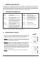
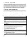
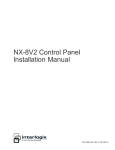
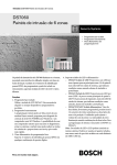
NetworX™ Series
NX-216E Zone Expander Module
Installation and Startup
© 2005 GE Security
All rights reserved.
These instructions do not purport to cover all details or variations in equipment nor to provide every
possible contingency to be met during installation, operation, and maintenance. If further information is
desired or if particular problems arise that are not covered sufficiently for the purchaser’s purpose, the
matter should be referred to GE Security.
This document contains proprietary information of GE Security and is furnished to its customer solely to
assist that customer in the installation, testing, operations, and/or maintenance of the equipment
described. This document shall not be reproduced in whole or in part nor shall its contents be disclosed
to any third party without the written approval of GE Security.
Please refer to the current GE Security product catalog for detailed warranty information.
Main
Outside the US
Main Fax
800-727-2339
903-845-6941
903-845-6811
Technical Support
Sales & Literature
888-437-3287
800-547-2556
Web: www.gesecurity.com
SAFETY SYMBOL LEGEND
Indicates a procedure, practice, condition, or statement that, if not strictly
observed, could result in personal injury.
* This symbol indicates electrical warnings and cautions.
Warning
Indicates a procedure, practice, condition, or statement that, if not strictly
observed, could result in damage to or destruction of equipment or property.
** This symbol indicates general warnings and cautions.
Caution
Note
Tip
Indicates an essential or important procedure, instruction, condition, or
statement.
Indicates a user tip. Provides helpful information that is not normally defined
in regular use, but from an experienced user.
TABLE OF CONTENTS
I.
GENERAL DESCRIPTION ............................................................................................................................. 4
II.
ORDERING INFORMATION......................................................................................................................... 4
III.
BOARD INSTALLATION ............................................................................................................................... 4
IV.
WIRING ............................................................................................................................................................. 5
V.
TERMINAL DESCRIPTION........................................................................................................................... 5
VI.
DIP SWITCH SETTINGS (6 POSITION) ...................................................................................................... 6
VII.
ENROLLING THE EXPANDER .................................................................................................................... 7
VIII.
DEFAULT ZONE CONFIGURATIONS ........................................................................................................ 7
IX.
ZONE CONFIGURATION AND PARTITION ............................................................................................. 9
X.
PROGRAMMING WORKSHEETS.............................................................................................................. 10
XI.
SPECIFICATIONS ......................................................................................................................................... 16
UNDERWRITERS LABORATORIES INFORMATION
The NX-216E is UL approved and listed in accordance with the following UL Standards (US & Canada):
UL365
Police Station Connected Burglar Alarm Units & Systems
UL609
Local Burglar Alarm Units & Systems
UL864
Control Units for Fire-Protective Signaling Systems
UL985
Household Fire Warning Systems
UL1023
Household Burglar Alarm Systems
UL1610
Central Station Burglar Alarm Units
NX-216E Zone Expander
3
GENERAL DESCRIPTION
I.
The NX-216E is a microprocessor-controlled 16-zone expander for the NetworX control panels (refer to
Compatibility chart on the back of this manual). Up to five NX-216E zone expander modules can be added to the
NX-8 or NX-8-CF control panels with a maximum zone count of 48 zones. Up to twenty-three expanders can be
added to the NX-8E and NX-8E-CF controls with a maximum zone count of 192 zones. Each expander has an
optional tamper switch and power isolator making it ideal for use in a remote location.
ORDERING INFORMATION
II.
PART #
DESCRIPTION
PART #
NX-216E
NX-8
16 Zone Expander
NX-8V2 Control Panel only (48 zones)
NX-320E
NX-408E #
NX-8-KIT
NX-8V2 Control, NX-108E LED Keypad, &
16.5V 40VA Transformer
NX-8 Commercial Fire Control Panel in
NX-003-CF Enclosure, (2) NX-148E-CF
LCD keypads; NX-870E Fire Supervision
module; 16.5V 50VA Transformer
NX-8E Control Panel only (192 zones)
NX-416E #
NX-8-CF-KIT
NX-8E
NX-448E #
NX-508E
NX-8E-KIT
NX-8E Control, NX-108E LED Keypad, &
NX-870E
16.5V 40VA Transformer
NX-8E-CF-KIT
NX-8E Commercial Fire Control Panel in
NX-003-CF
NX-003-CF Enclosure, (2) NX-148E-CF
LCD keypads; NX-870E Fire Supervision
module; 16.5V 50VA Transformer
#
These wireless devices are UL listed for residential applications only.
DESCRIPTION
Remote Power Supply
8 Zone Wireless Expansion Module
(UL LISTED PART #60-904)
16 Zone Wireless Expansion Module
(UL LISTED PART #60-904)
48 Zone Wireless Expansion Module
(UL LISTED PART #60-904)
Eight Output Module
Fire Supervision Module
Commercial Fire Enclosure (Red)
Please refer to the GE Security product catalog for warranty details.
III.
BOARD INSTALLATION
Inside the can, several 2-holed insertion points have been constructed. This
allows for either vertical or horizontal placement of the modules. Notice that each
insertion point has two sizes of holes -a larger hole and a smaller hole.
Diagram 1: The black plastic PCB guides are grooved on one edge where the
PC board will be seated. The end with the half-moon protrusion fits into the
larger hole. The smaller hole is for the screw.
Diagram 2: Place the first black plastic PCB guide in the top insertion point,
grooved edge downward. The half-moon protrusion will be in the large hole. It
does not require force. Insert one of the provided screw into the smaller hole
(from inside the can) to secure it in place. A screwdriver should reach through
the notch that runs the length of the guide to tighten the screw. The second PBC
guide should be positioned opposite the first (grooved edge up) and placed in the
lower insertion point, using the same procedures described above. Once
mounted, screw it in securely.
Diagram 3: The PC Board should slide freely in the grooves of both guides.
4
NX-216E Zone Expander
WIRING
IV.
Any unused zones must have the EOL resistor across it (unless all eight are
disabled by dip switch 6).
Figure IV—1
TERMINAL DESCRIPTION
V.
POS
COM
DATA
TAM
AUX
Z9
COM
Z10
Z11—Z24
Connect to the KP POS terminal of the NetworX control panel (refer to Compatibility chart on the back
of this manual). Current draw is 30 mA.
Connect to the KP COM terminal of the control panel.
Connect to the KP DATA terminal of the control panel. (See the wiring diagram for wire specifications)
Connect as shown on diagram. IF NOT USED, CONNECT TO A COM TERMINAL.
Can be used to power devices directly from the NX-216E. Power is coming from the control panel
therefore the current draw of these devices must be added to the total current draw of the NX-216E.
This output is current limited to 100 mA.
Connect to one side of zone 9 loop. Connect the other side to COM terminal. Open or short causes
alarm. (See wiring diagram for examples)
Common (-) terminal for zones 9 & 10.
Connect to one side of zone 10 loop. Connect the other side to COM terminal. Open or short causes
alarm. (See wiring diagram for examples).
Connect as described for Z9 & Z10.
NX-216E Zone Expander
5
VI.
DIP SWITCH SETTINGS (6 position)
The first thing that must be decided is the starting zone of this particular zone expander. The starting zone must be
on a boundary of eight (8) zones. The sixteen (16) zones for this module will move out from this starting position.
To set the starting zone, set the dip switch according to the table below:
THE POSITION OF ALL SWITCHES IS ONLY UPDATED WHEN THE NX-216E IS POWERED UP.
BEFORE YOU CHANGE THE POSITION OF THESE SWITCHES YOU MUST POWER DOWN THE EXPANDER.
Starting Zone #
9
Expander #
22
Switch 1
OFF
Switch 2
OFF
Switch 3
OFF
Switch 4
OFF
Switch 5
OFF
9
23
ON
OFF
OFF
OFF
OFF
17
16
OFF
ON
OFF
OFF
OFF
25
17
ON
ON
OFF
OFF
OFF
33
18
OFF
OFF
ON
OFF
OFF
41
19
ON
OFF
ON
OFF
OFF
49
20
OFF
ON
ON
OFF
OFF
57
21
ON
ON
ON
OFF
OFF
65
96
OFF
OFF
OFF
ON
OFF
73
97
ON
OFF
OFF
ON
OFF
81
98
OFF
ON
OFF
ON
OFF
89
99
ON
ON
OFF
ON
OFF
97
100
OFF
OFF
ON
ON
OFF
105
101
ON
OFF
ON
ON
OFF
113
102
OFF
ON
ON
ON
OFF
121
103
ON
ON
ON
ON
OFF
129
104
OFF
OFF
OFF
OFF
ON
137
105
ON
OFF
OFF
OFF
ON
145
106
OFF
ON
OFF
OFF
ON
153
107
ON
ON
OFF
OFF
ON
161
108
OFF
OFF
ON
OFF
ON
169
109
ON
OFF
ON
OFF
ON
177
110
OFF
ON
ON
OFF
ON
185
111
ON
OFF
ON
ON
ON
Dip switch 6 - Dip switch 6 is used to disable the second block of eight (8) zones on this zone expander. This can
be done if only an eight- (8) zone expander is required in a particular expander location. To disable the second
group of eight (8) zones on this expander, turn dip switch 6 on.
6
NX-216E Zone Expander
VII. ENROLLING THE EXPANDER
The NetworX control panels have the ability to automatically find and store in memory the presence of all keypads,
zone expanders, wireless receivers and any other module connected to the data terminal. (Refer to Compatibility
chart on the back of this manual). This allows these modules to be supervised by the control panel. To enroll the
modules enter the Program Mode of the control panel (refer to the installation manual for the specific control panel).
When the Program Mode is exited, it will automatically enroll the devices. The enrolling process takes about 12
seconds, during which time the “Service” LED will illuminate. User codes will not be accepted during the enrolling
process. Once a module is enrolled, if it is not detected by the control, the “Service” LED will illuminate.
VIII. DEFAULT ZONE CONFIGURATIONS
Zones can be programmed to be one of thirty different zone configurations (zone types). Configurations # 17
through 20 can be used for wireless or hardwired zones using European double EOL configuration. The default
zone configurations are listed below. These zone configurations can be customized by programming locations 110
to 169.
All Fire Zones are pre-programmed for UL systems.
Zone Types 21-30 are applicable to the NX-8E and NX-8E-CF control panels ONLY.
The expander zones will not follow the Fast Loop Response.
DATA
1
2
3
4
5
6
7
8
9
10
11
12
13
DESCRIPTION OF DEFAULT CONFIGURATION
DAY ZONE - Instant when system is armed trouble zone when system is disarmed.
24-HOUR AUDIBLE - Creates an instant yelping siren alarm regardless of the armed state of the
panel.
ENTRY/EXIT DELAY 1 - A trip will start entry delay 1. The lack of a trip during exit delay will enable
the Automatic Bypass or Instant mode if so programmed.
FOLLOWER WITH AUTO-BYPASS DISABLED - This zone will be instant when the system is
armed and no entry or exit delays are being timed. It is delayed during entry and exit delay times.
This zone will not bypass in Stay Mode, nor automatically bypass even if enabled in Segment 1 /
Location 23.
INTERIOR FOLLOWER WITH AUTO- BYPASS ENABLED - This zone will be instant when the
system is armed and no entry or exit delay is being timed. It is delayed during entry and exit delay
times. This zone will bypass in Stay Mode, and automatically bypass if enabled in Segment 1 of
Location 23.
INSTANT - This zone creates an instant alarm whenever it is tripped and the Armed LED is on.
24-HOUR SILENT - Creates an instant silent alarm regardless of the armed state of the control
panel. It will not display on the keypad.
FIRE - This zone will illuminate the Fire LED and sound the temporal siren each time the zone is
shorted. It will also rapidly flash the Fire LED indicating a trouble if the zone is open.
ENTRY/EXIT DELAY 2 - A trip will start entry delay 2. The lack of a trip during exit delay will enable
the Automatic Bypass or Instant mode if so programmed.
24-HOUR SILENT SUPERVISED - Creates an instant silent alarm regardless of the armed state of
the control panel. It will display on the keypad.
KEYSWITCH ZONE - This zone type will arm and disarm the partition or partitions of the control
panel that resides in each time the zone is shorted. Keyswitch arming will report as user #99.
INTERIOR FOLLOWER WITH "CROSS ZONE" ENABLED - This zone will be Instant when the
system is armed and no entry or exit delay is being timed. It is delayed during entry and exit delay
times. If a "Cross Zone" is not being timed it will start a "Cross Zone" timer. If a "Cross Zone" is being
timed it will create an Instant alarm. This zone will bypass in Stay Mode and automatically bypass
when enabled in Segment 1 of Location 23.
INSTANT ENTRY GUARD - This zone creates an instant alarm whenever it is tripped and the Stay
LED is off. It will start an entry delay time 2 if it is tripped and the system is armed and the Stay LED
is on.
NX-216E Zone Expander
7
DATA
14
15
16
17
18
19
20
DESCRIPTION OF DEFAULT CONFIGURATION
ENTRY/EXIT DELAY 1 WITH GROUP BYPASS ENABLED - A trip will start entry delay 1. This
zone will bypass when the "Group Bypass" command is entered at the keypad. The lack of a trip
during exit delay will enable the Automatic Bypass or Instant mode if so programmed.
INTERIOR FOLLOWER WITH GROUP BYPASS ENABLED - This zone will be instant when the
system is armed and no entry or exit delays are being timed. It is delayed during entry/exit delay
times. This zone will bypass when the "Group Bypass" command is entered at the keypad. This zone
will bypass in Stay Mode and automatically bypass even if enabled in Segment 1 / Location 23.
INSTANT WITH GROUP BYPASS ENABLED - This zone creates an instant alarm whenever it is
tripped and the Armed LED is on. This zone will bypass when the "Group Bypass" command is
entered at the keypad.
ENTRY/EXIT DELAY 1 WITH TAMPER ENABLED - A trip will start entry delay 1. The lack of a trip
during exit delay will enable the Automatic Bypass or Instant mode if so programmed. This
configuration group can be used to enable tamper on a wireless transmitter.
INTERIOR FOLLOWER WITH TAMPER AND AUTO-BYPASS ENABLED - This zone will be
instant when the system is armed and no entry or exit delay is being timed. It is delayed during entry
and exit delay times. This zone will bypass in Stay Mode and automatically bypass if enabled in
Segment 1 / Location 23. This configuration group can be used to enable tamper on a wireless
transmitter.
INSTANT WITH TAMPER ENABLED - This zone creates an instant alarm whenever it is tripped and
the Armed LED is on. This configuration group can be used to enable tamper on a wireless
transmitter.
ENTRY/EXIT DELAY 2 WITH TAMPER ENABLED - A trip will start entry delay 2. The lack of a trip
during exit delay will enable the Automatic Bypass or Instant mode if so programmed. This
configuration group can be used to enable tamper on a wireless transmitter.
Zone Types 21-30 are applicable to the NX8-E and NX-8E-CF control panels ONLY
21
22
23
24
25
26
27
28
29
30
8
GAS DETECTION- Creates an instant alarm regardless of the armed state of the control panel. It will
display on the keypad and activate the keypad sounder.
LOW TEMP DETECTION- Creates an instant silent alarm regardless of the armed state of the
control panel. It will display on the keypad and activate the keypad sounder.
HIGH TEMP DETECTION- Creates an instant silent alarm regardless of the armed state of the
control panel. It will display on the keypad and activate the keypad sounder.
MANUAL FIRE - This zone will illuminate the Fire LED and sound the temporal siren each time the
zone is shorted. It will also rapidly flash the Fire LED indicating a trouble if the zone is open.
CHIME ONLY - Creates no alarm regardless of the armed state of the control panel. It will chime
anytime it is faulted and will display on the keypad. Local only.
INTERIOR FOLLOWER DELAY 2 - This zone will be instant when the system is armed and no entry
or exit delay is being timed. It is delayed during entry and exit delay 2 times. This zone will
automatically bypass if enabled in Segment 1 of Location 23.
INTERIOR FOLLOWER FORCE ARMABLE - This zone will be instant when the system is armed
and no entry or exit delay is being timed. It is delayed during entry and exit delay 1 times. This zone
will automatically bypass if enabled in Segment 1 of Location 23.
ENTRY/EXIT FORCE ARMABLE DELAY 2 - A trip will start entry delay 2. The lack of a trip during
exit delay will enable the Automatic Bypass or Instant mode if so programmed.
INTERIOR FOLLOWER WITH ACTIVITY SUPERVISION ENABLED - This zone will be instant
when the system is armed and no entry or exit delay is being timed. It is delayed during entry and exit
delay times. It will send a report if the zone activity time is reached without a change of state. Refer
to Location 40 / Segment 11. This zone will automatically bypass if enabled in Segment 1 of Location
23.
ENTRY/EXIT WITH ACTIVITY SUPERVISION ENABLED- A trip will start entry delay 1. It will send a
report if the zone activity time is reached without a change of state. Refer to Location 40 / Segment
11. The lack of a trip during exit delay will enable the Automatic Bypass or Instant mode if so
programmed.
NX-216E Zone Expander
IX.
ZONE CONFIGURATION AND PARTITION
The programming for all zone information is performed in the NetworX control panels (refer to Compatibility chart on
the back of this manual). For instructions on accessing and programming the control panel as well as changing the
characteristics of a configuration group, refer to the installation manual for the corresponding control panel. The
following programming information is taken from the NX-8 Installation Manual.
LOCATION 25 CONFIGURATION GROUP ZONES 1-8
(8 segments, numerical data) Location 25 contains the Configuration Group (Zone type) for zones 1-9. Segment 1
is for zone 1; Segment 8 is for zone 8. Default configurations are found in the table on page 7.
LOCATION 26 PARTITION SELECT ZONES 1-8
(8 segments, feature selection data) Location 26 is used to select the partition(s) that zones 1-8 reside in. A zone
may reside in any combination of the 8 partitions. If a burglary zone resides in more than 1 partition, it will only
be active when all partitions are armed. A zone that resides in more than 1 partition will be reported to its
lowest partition. Location 28 has 8 segments. Segment 1 corresponds to zone 1 and Segment 8 corresponds to
zone 8.
Segments 1 - 8:
1 = Partition # 1
2 = Partition # 2
3 = Partition # 3
4 = Partition # 4
5 = Partition # 5
6 = Partition # 6
7 = Partition # 7
8 = Partition # 8
LOCATIONS 27 – 36;
LOCATIONS 170 – 205 (Available on NX-8E and NX-8E-CF only)
These locations contain the Configuration Group and Partition Select for Zones 9 – 192. Use the instructions
associated with Location 25 and 26 to program the remaining locations. Worksheets for these locations are
included for your convenience.
NX-216E Zone Expander
9
X.
LOC
27
28
29
30
31
32
33
34
10
PROGRAMMING WORKSHEETS
DESCRIPTION
ZONES 9 - 16 CONFIGURATION GROUP
ZONES 9 - 16 PARTITION SELECT
Segment
1
2
3
Zone
9
10
11
1
1
1
2
2
2
3
3
3
4
4
4
5
5
5
6
6
6
7
7
7
8
8
8
ZONES 17 – 24 CONFIGURATION GROUP
ZONES 17 – 24 PARTITION SELECT
Segment
1
2
3
Zone
17
18
19
1
1
1
2
2
2
3
3
3
4
4
4
5
5
5
6
6
6
7
7
7
8
8
8
ZONES 25 – 32 CONFIGURATION GROUP
ZONES 25 – 32 PARTITION SELECT
Segment
1
2
3
Zone
25
26
27
1
1
1
2
2
2
3
3
3
4
4
4
5
5
5
6
6
6
7
7
7
8
8
8
ZONES 33 – 40 CONFIGURATION GROUP
ZONES 33 – 40 PARTITION SELECT
Segment
1
2
3
Zone
33
34
35
1
1
1
2
2
2
3
3
3
4
4
4
5
5
5
6
6
6
7
7
7
8
8
8
DEFAULT
6-6-6-6-6-6-6-6
DATA
4
12
1
2
3
4
5
6
7
8
5
13
1
2
3
4
5
6
7
8
6-6-6-6-6-6-6-6
6
14
1
2
3
4
5
6
7
8
7
15
1
2
3
4
5
6
7
8
8
16
1
2
3
4
5
6
7
8
4
20
1
2
3
4
5
6
7
8
5
21
1
2
3
4
5
6
7
8
6-6-6-6-6-6-6-6
6
22
1
2
3
4
5
6
7
8
7
23
1
2
3
4
5
6
7
8
8
24
1
2
3
4
5
6
7
8
4
28
1
2
3
4
5
6
7
8
5
29
1
2
3
4
5
6
7
8
6-6-6-6-6-6-6-6
6
30
1
2
3
4
5
6
7
8
7
31
1
2
3
4
5
6
7
8
8
32
1
2
3
4
5
6
7
8
6
38
1
2
3
4
5
6
7
8
7
39
1
2
3
4
5
6
7
8
8
40
1
2
3
4
5
6
7
8
4
36
1
2
3
4
5
6
7
8
5
37
1
2
3
4
5
6
7
8
NX-216E Zone Expander
LOC
35
36
DESCRIPTION
ZONES 41 – 48 CONFIGURATION GROUP
ZONES 41 – 48 PARTITION SELECT
Segment
1
2
3
Zone
41
42
43
1
1
1
2
2
2
3
3
3
4
4
4
5
5
5
6
6
6
7
7
7
8
8
8
DEFAULT
6-6-6-6-6-6-6-6
4
44
1
2
3
4
5
6
7
8
5
45
1
2
3
4
5
6
7
8
DATA
6
46
1
2
3
4
5
6
7
8
7
47
1
2
3
4
5
6
7
8
8
48
1
2
3
4
5
6
7
8
NOTE: THE FOLLOWING LOCATIONS ARE ONLY AVAILABLE ON THE NX8-E and NX-8E-CF PANELS
170
171
172
173
174
175
ZONES 49 – 56 CONFIGURATION GROUP
ZONES 49 – 56 PARTITION SELECT
Segment
1
2
3
Zone
49
50
51
1
1
1
2
2
2
3
3
3
4
4
4
5
5
5
6
6
6
7
7
7
8
8
8
ZONES 57 – 64 CONFIGURATION GROUP
ZONES 57 – 64 PARTITION SELECT
Segment
1
2
3
Zone
57
58
59
1
1
1
2
2
2
3
3
3
4
4
4
5
5
5
6
6
6
7
7
7
8
8
8
ZONES 65 – 72 CONFIGURATION GROUP
ZONES 65 – 72 PARTITION SELECT
Segment
1
2
3
Zone
65
66
67
1
1
1
2
2
2
3
3
3
4
4
4
5
5
5
6
6
6
7
7
7
8
8
8
NX-216E Zone Expander
6-6-6-6-6-6-6-6
4
52
1
2
3
4
5
6
7
8
5
53
1
2
3
4
5
6
7
8
6-6-6-6-6-6-6-6
6
54
1
2
3
4
5
6
7
8
7
55
1
2
3
4
5
6
7
8
8
56
1
2
3
4
5
6
7
8
4
60
1
2
3
4
5
6
7
8
5
61
1
2
3
4
5
6
7
8
6-6-6-6-6-6-6-6
6
62
1
2
3
4
5
6
7
8
7
63
1
2
3
4
5
6
7
8
8
64
1
2
3
4
5
6
7
8
6
70
1
2
3
4
5
6
7
8
7
71
1
2
3
4
5
6
7
8
8
72
1
2
3
4
5
6
7
8
4
68
1
2
3
4
5
6
7
8
5
69
1
2
3
4
5
6
7
8
11
LOC
176
177
178
179
180
181
182
183
12
DESCRIPTION
ZONES 73 – 80 CONFIGURATION GROUP
ZONES 73 – 80 PARTITION SELECT
Segment
1
2
3
Zone
73
74
75
1
1
1
2
2
2
3
3
3
4
4
4
5
5
5
6
6
6
7
7
7
8
8
8
ZONES 81 – 88 CONFIGURATION GROUP
ZONES 81 – 88 PARTITION SELECT
Segment
1
2
3
Zone
81
82
83
1
1
1
2
2
2
3
3
3
4
4
4
5
5
5
6
6
6
7
7
7
8
8
8
ZONES 89 – 96 CONFIGURATION GROUP
ZONES 89 – 96 PARTITION SELECT
Segment
1
2
3
Zone
89
90
91
1
1
1
2
2
2
3
3
3
4
4
4
5
5
5
6
6
6
7
7
7
8
8
8
ZONES 97 – 104 CONFIGURATION GROUP
ZONES 97 – 104 PARTITION SELECT
Segment
1
2
3
Zone
97
98
99
1
1
1
2
2
2
3
3
3
4
4
4
5
5
5
6
6
6
7
7
7
8
8
8
DEFAULT
6-6-6-6-6-6-6-6
DATA
4
76
1
2
3
4
5
6
7
8
5
77
1
2
3
4
5
6
7
8
6-6-6-6-6-6-6-6
6
78
1
2
3
4
5
6
7
8
7
79
1
2
3
4
5
6
7
8
8
80
1
2
3
4
5
6
7
8
4
84
1
2
3
4
5
6
7
8
5
85
1
2
3
4
5
6
7
8
6-6-6-6-6-6-6-6
6
86
1
2
3
4
5
6
7
8
7
87
1
2
3
4
5
6
7
8
8
88
1
2
3
4
5
6
7
8
4
92
1
2
3
4
5
6
7
8
5
93
1
2
3
4
5
6
7
8
6-6-6-6-6-6-6-6
6
94
1
2
3
4
5
6
7
8
7
95
1
2
3
4
5
6
7
8
8
96
1
2
3
4
5
6
7
8
6
102
1
2
3
4
5
6
7
8
7
103
1
2
3
4
5
6
7
8
8
104
1
2
3
4
5
6
7
8
4
100
1
2
3
4
5
6
7
8
5
101
1
2
3
4
5
6
7
8
NX-216E Zone Expander
LOC
184
185
186
187
188
189
190
191
DESCRIPTION
ZONES 105 – 112 CONFIGURATION GROUP
ZONES 105 – 112 PARTITION SELECT
Segment
1
2
3
Zone
105
106
107
1
1
1
2
2
2
3
3
3
4
4
4
5
5
5
6
6
6
7
7
7
8
8
8
ZONES 113 – 120 CONFIGURATION GROUP
ZONES 113 – 120 PARTITION SELECT
Segment
1
2
3
Zone
113
114
115
1
1
1
2
2
2
3
3
3
4
4
4
5
5
5
6
6
6
7
7
7
8
8
8
ZONES 121 – 128 CONFIGURATION GROUP
ZONES 121 – 128 PARTITION SELECT
Segment
1
2
3
Zone
121
122
123
1
1
1
2
2
2
3
3
3
4
4
4
5
5
5
6
6
6
7
7
7
8
8
8
ZONES 129 – 136 CONFIGURATION GROUP
ZONES 129 – 136 PARTITION SELECT
Segment
1
2
3
Zone
129
130
131
1
1
1
2
2
2
3
3
3
4
4
4
5
5
5
6
6
6
7
7
7
8
8
8
NX-216E Zone Expander
DEFAULT
6-6-6-6-6-6-6-6
DATA
4
108
1
2
3
4
5
6
7
8
5
6
109
110
1
1
2
2
3
3
4
4
5
5
6
6
7
7
8
8
6-6-6-6-6-6-6-6
7
111
1
2
3
4
5
6
7
8
8
112
1
2
3
4
5
6
7
8
4
116
1
2
3
4
5
6
7
8
5
6
117
118
1
1
2
2
3
3
4
4
5
5
6
6
7
7
8
8
6-6-6-6-6-6-6-6
7
119
1
2
3
4
5
6
7
8
8
120
1
2
3
4
5
6
7
8
4
124
1
2
3
4
5
6
7
8
5
6
125
126
1
1
2
2
3
3
4
4
5
5
6
6
7
7
8
8
6-6-6-6-6-6-6-6
7
127
1
2
3
4
5
6
7
8
8
128
1
2
3
4
5
6
7
8
7
135
1
2
3
4
5
6
7
8
8
136
1
2
3
4
5
6
7
8
4
132
1
2
3
4
5
6
7
8
5
133
1
2
3
4
5
6
7
8
6
134
1
2
3
4
5
6
7
8
13
LOC
192
193
194
195
196
197
198
199
14
DESCRIPTION
ZONES 137 – 144 CONFIGURATION GROUP
ZONES 137 – 144 PARTITION SELECT
Segment
1
2
3
Zone
137
138
139
1
1
1
2
2
2
3
3
3
4
4
4
5
5
5
6
6
6
7
7
7
8
8
8
ZONES 145 – 152 CONFIGURATION GROUP
ZONES 145 – 152 PARTITION SELECT
Segment
1
2
3
Zone
145
146
147
1
1
1
2
2
2
3
3
3
4
4
4
5
5
5
6
6
6
7
7
7
8
8
8
ZONES 153 – 160 CONFIGURATION GROUP
ZONES 153 – 160 PARTITION SELECT
Segment
1
2
3
Zone
153
154
155
1
1
1
2
2
2
3
3
3
4
4
4
5
5
5
6
6
6
7
7
7
8
8
8
ZONES 161 – 168 CONFIGURATION GROUP
ZONES 161 – 168 PARTITION SELECT
Segment
1
2
3
Zone
161
162
163
1
1
1
2
2
2
3
3
3
4
4
4
5
5
5
6
6
6
7
7
7
8
8
8
DEFAULT
6-6-6-6-6-6-6-6
DATA
4
140
1
2
3
4
5
6
7
8
5
6
141
142
1
1
2
2
3
3
4
4
5
5
6
6
7
7
8
8
6-6-6-6-6-6-6-6
7
143
1
2
3
4
5
6
7
8
8
144
1
2
3
4
5
6
7
8
4
148
1
2
3
4
5
6
7
8
5
6
149
150
1
1
2
2
3
3
4
4
5
5
6
6
7
7
8
8
6-6-6-6-6-6-6-6
7
151
1
2
3
4
5
6
7
8
8
152
1
2
3
4
5
6
7
8
4
156
1
2
3
4
5
6
7
8
5
6
157
158
1
1
2
2
3
3
4
4
5
5
6
6
7
7
8
8
6-6-6-6-6-6-6-6
7
159
1
2
3
4
5
6
7
8
8
160
1
2
3
4
5
6
7
8
7
167
1
2
3
4
5
6
7
8
8
168
1
2
3
4
5
6
7
8
4
164
1
2
3
4
5
6
7
8
5
165
1
2
3
4
5
6
7
8
6
166
1
2
3
4
5
6
7
8
NX-216E Zone Expander
LOC
200
201
202
203
204
205
DESCRIPTION
ZONES 169 – 176 CONFIGURATION GROUP
ZONES 169 – 176 PARTITION SELECT
Segment
1
2
3
Zone
169
170
171
1
1
1
2
2
2
3
3
3
4
4
4
5
5
5
6
6
6
7
7
7
8
8
8
ZONES 177 – 184 CONFIGURATION GROUP
ZONES 177 – 184 PARTITION SELECT
Segment
1
2
3
Zone
177
178
179
1
1
1
2
2
2
3
3
3
4
4
4
5
5
5
6
6
6
7
7
7
8
8
8
ZONES 185 – 192 CONFIGURATION GROUP
ZONES 185 – 192 PARTITION SELECT
Segment
1
2
3
Zone
185
186
187
1
1
1
2
2
2
3
3
3
4
4
4
5
5
5
6
6
6
7
7
7
8
8
8
NX-216E Zone Expander
DEFAULT
6-6-6-6-6-6-6-6
DATA
4
172
1
2
3
4
5
6
7
8
5
6
173
174
1
1
2
2
3
3
4
4
5
5
6
6
7
7
8
8
6-6-6-6-6-6-6-6
7
175
1
2
3
4
5
6
7
8
8
176
1
2
3
4
5
6
7
8
4
180
1
2
3
4
5
6
7
8
5
6
181
182
1
1
2
2
3
3
4
4
5
5
6
6
7
7
8
8
6-6-6-6-6-6-6-6
7
183
1
2
3
4
5
6
7
8
8
184
1
2
3
4
5
6
7
8
7
191
1
2
3
4
5
6
7
8
8
192
1
2
3
4
5
6
7
8
4
188
1
2
3
4
5
6
7
8
5
189
1
2
3
4
5
6
7
8
6
190
1
2
3
4
5
6
7
8
15
XI.
SPECIFICATIONS
OPERATING POWER
12VDC Supplied from NetworX control panel or NX-320E
AUXILIARY POWER
Supplied from NetworX control or NX-320E
Current limited to 100mA
CURRENT DRAW
30mA
LOOP RESISTANCE
300 Ohms Maximum
LOOP RESPONSE
Selectable 50mS or 500mS
OPERATING TEMPERATURE
32 to 120 degrees F
DIMENSIONS
6.0" Wide
2.125" High
1.0" Deep
SHIPPING WEIGHT
2 lbs.
COMPATIBLE CONTROL PANELS:
NETWORX PANEL
NX-8
NX-8-CF
NX-8E
NX-8E-CF
Main
Outside the US
Main Fax
NX216EIE05
REV E
800-727-2339
903-845-6941
903-845-6811
(MAY 2005)
MAX NX-216E MODULES
5
5
23
23
MAX ZONE COUNT
48
48
192
192
Technical Support
888-437-3287
Sales & Literature
800-547-2556
Web: www.ge-security.com