1
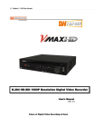
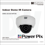
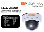
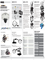
Template Sheet
Template Sheet
PREPARATION
INSTALLATION
The following items are included with your MEGApix Camera
DWC-MF21M4TIR
DWC-MF21M8TIR
DWC-MF21M4TIR
DWC-MF21M8TIR
IP 2.1MP Flush Mount Vandal Dome IR Camera
Quick Start
Guide
Quick Setup Guide
CD
(Manual &
Software)
IP 2.1MP Low Profile Vandal Dome IR Camera
Quick Setup Guide
2 Mounting Nuts
& 2 Mounting
Screws
Metal Mount Plate
L-Wrench
Mounting
Template for
Camera and
Metal Mount
Plate
2
3 Screws & 3
Dry Wall
Anchors
Low Profile Vandal
Dome IR Camera
- 12VDC Power
- RJ45 Network
Thank you for purchasing Digital Watchdog’s MEApix Flat Vandal Dome Camera.
Before installing the camera, please verify your model and read this guide carefully.
Easy Camera Installation
Installation Using Mount Plate
1. Detach the camera’s cover dome from the
camera’s module by unscrewing the three
cover dome screws using the L-Wrench.
2. Use the camera or mounting template to
mark and drill the necessary holes in the
wall or ceiling.
3. Pull wires through and make connections.
4. Using three (3) included screws mount
and secure the camera to the wall or ceiling.
5. Secure the camera’s cover dome onto the
camera base to complete the installation.
1. Detach the camera’s cover dome
from the camera’s module by
unscrewing the three cover dome
screws.
2. Using the metal mount plate, mark
and drill the necessary holes in the wall
or ceiling.
3. Pull wires through and make
connections.
4. Using the three (3) included screws,
mount and secure the camera to the
wall or ceiling.
5. Attach the camera base to the metal
mount by snapping it into place using
the two metal handles.
6. Secure the camera’s cover dome
onto the camera base to complete the
installation.
Installation Using Mount Bolt & Nut
1. Detach the camera’s cover dome
from the camera’s module by
unscrewing the three cover dome
screws.
2. Using the camera or mounting
template, mark and drill the necessary
holes in the wall or ceiling.
3. Secure the two long mounting
screws to the camera’s base.
4. Pull wires through and make
connections.
5. Mount the camera to the mounting
surface using the 2 mounting nuts.
6. Secure the camera’s cover dome
onto the camera base to complete the
installation.
2
Parts and Description
Tilt Stopper Screw
Lens
Recommended Settings
There are two options.*
Camera Default Color Settings
Using a PoE-Enabled Switch
To adjust the camera’s orientation:
1. Loosen the tilt stopper screw at the
base of the camera’s Gibmal by
rotating it counter clock-wise.
2. Move the camera to the desired
angle.
3. Secure the camera’s lens position by
screwing the tilt stopper screw
clock-wise.
Camera Specifications
Micro SD Card Slot
DC Power Cable
RJ-45 Cable
Resetting the Camera
2
Pressing the reset button on the camera’s control board for five (5) seconds will
initialize all environmental variables to factory default. Previous setup for IP default,
time, etcetera will be deleted. If a system IP address is lost, reset the camera back
to factory default.The following are the default network settings:
4
SPECIFICATIONS
Please refer to the table below for the default camera settings.
You can reset the camera’s settings to its default color settings by
pressing the ‘Default’ button at the bottom of the screen.
The MEGApix Camera is PoE-compliant, allowing transmission of power
and data via a single ethernet cable. Follow the illustrations below to
connect the camera to a PoE-enabled switch using an ethernet cable.
Reset Button
Adjusting the Camera’s Angle
3
Network Connection
1
INSTALLATION
IMAGE
Image Sensor
Effective Pixels
Minimum Scene Illumination
LENS
Focal Length
F2.0 (30IRE): 2.4 Lux [Color], F2.0 (30IRE): 0.5 Lux [B/W]
Zoom
Lens Type
IR Distance
Angle of View
NETWORK
LAN
Video Compression Type
Resolution
Frame Rate
12x Digitzl Zoom
Fixed Lens
30ft Range IR
Horizontal: 42o Wide Angle
If a PoE-enabled switch is not used, use a power adaptor to connect the
MEGAPIX Camera to a Non-PoE switch.
DHCP
192.168.1.123
255.255.255.0
192.168.1.123
7000
80
7001
Dual-Stream at Different Rates and Resolutions
IPv4, IPv6
Protocol
TCP/IP, HTTP, DHCP, PPPoE, ICMP, ARP, RARP,
RTSP, NTP, UDP, Multicast
5 Users
ONVIF Conformance
Yes
Web Viewer
OS: Windows XP / Vista / 7, MAC OS
Browser: Internet Explorer, Chrome, Firefox, Safari
NxMS, DW Spectrum, Pivot
Video Management Software
Memory Slot
Frequent use may cause a System Error
TEL: (866) 446-3595
www.Digital-Watchdog.com / [email protected]
Technical Support Hours: Monday-Friday 9:00AM to 8:00PM EST
Reset Button
!
5
20 140122
6
7
802.3 Compliance 10/100 LAN
H.264, MPEG4, MJPEG (Super Fine~Low)
1920X1080 (16:9) ~ 320X240 (4:3)
Up to 30fps at All Resolutions
Streaming Capability
ENVIRONMENTAL
Operating Temperature/ Humidity
IP Mode
IP Address
Subnet Mask
Gateway
Command Port
HTTP Port
Live Port
4.0mm [DWC-MF21M4TIR] / 8.0mm [DWC-MF21M8TIR]
IP
Maximum User Access
Using a Non-PoE Switch
1/2.8” Sony CMOS Sensor
1920 (H) X 1080 (V)
24 hours recording to Micro SDHC Card (4GB-32GB)
Card Not Included*
-10oC ~ 50oC (14oF ~ 122oF)
Operating Humidity
IP Rating
Other Certifications
ELECTRICAL
Power Requirement
Power Consumption
MECHANICAL
Material
Dimensions
Less than 90% (Non-Condensing)
IP66 (Protects against dust and high pressure water)
CE, FCC, RoHS
Weight
1.0 lbs
DC 12V, PoE (IEEE802.3af Class 2)
3.6W, 300mA / LED ON: 4.3W, 360mA
Aluminum Housing
125 x 74.3 mm (4.9 X 2.9 in)
8
MEGApix CAMERA SETUP
Installing IP Finder
IP Finder searches for all the available network devices on your local
area network.
1
Install
IP Finder to find your MEGApix Camera on the local
network. The IP Finder software is on the included mini-CD. Run IP Finder
and install onto your PC.
2
When setup is complete, launch the IP Finder software.
3
To find your MEGApix camera, click Search button. Your MEGApix camera
will appear as “DWC-MF21M4TIR.”
4
To access the camera directly via Internet Explorer, select the desired device
and click Web Connect.
5
To change basic network settings through the IP Finder software, select the
desired device and click Configuration.
Setting the Camera on IP Finder
Setting the Camera on IP Finder
Accessing the Camera
Set the Camera for Internal Use
If you wish to connect your MEGApix Camera internally from within the same
network:
1
Find your MEGApix Camera on IP Finder software and click
Configuration.
Select an IP Configuration Mode - DHCP, PPPoE, or Static - that is
2
available to you. Recommended Setting is DHCP.*
3
If you wish to use DDNS, select the Use DDNS option. See page 10 for
further information.
4
When the setup is complete, select Apply.
5
Then, select Reboot button. The rebooting process usually takes up to a
minute.
6
Select Exit.
7
On the IP Finder window, select Search and comfirm that your changes
have been made.
User can use the IP Finder software to setup the basic network
Accessing the Camera
settings.
1
3
5
Webviewer Specifications
10
CPU
RAM
HDD
OS
Resolution
Intel P4 2.0GHz Dual Core
More than 1GB
200GB Required for Saving Clip Image
Microsoft Windows XP or Higher
Higher than 1024X768
Alarm Status
Computer’s Date & Time
Camera’s Name
Full Screen Mode
Camera’s Time
Access Setup
Menu
Export Camera’s
Display as JPEG
Print Camera’s
Current Display
Start/ Stop Instant
Recording
Stream’s Name Camera’s IP
Address
Stream Control
Enter the IP address of the camera on the Internet Explorer window.
Example: http://192.168.1.123 (Factory Default)
2 Enter Username and Password.
Username: admin
Password: admin
3 The web browser will ask to install Active-X Control. Once it has been installed,
Internet Explorer will display video images from the camera.
1
Minimum Requirements for PC
Export & Print
Instant Recording
Instantly record live video to your local drive.
4
3
Static IP: This option will assign a static (fixed) IP to your camera. A
static IP address will prevent the network from changing the camera’s IP
address and make it easier to access, especially when the camera is on a
large network and accessed by multiple users. Contact your Internet Service
Provider for more information.*
Use DDNS: Check this option to use DDNS (Dynamic DNS). DDNS
4
allows users to setup a unique URL for the IP camera. To use DDNS, you
must register for a DDNS ID from a DDNS Hosting Service.*
Port: This section displays all the port numbers that are required for
5
remote communication.
Set the Camera for External Use
If you wish to connect your MEGApix Camera to an external network,
please use Static IP.
1
Find your MEGApix Camera on IP Finder software and click
Configuration.
Select Static IP Configuration Mode.
2
3
If you wish to use DDNS, select the Use DDNS option. See page 10
for further information.
4
When the setup is complete, select Apply.
5
Then, select Reboot button. The rebooting process usually takes up to
a minute.
6
Select Exit.
7
On the IP Finder window, select Search and comfirm that your
changes have been made.
9
2
1
DHCP: If DHCP is selected, an IP
address will automatically be assigned
to the camera. If your network does not
support DHCP, a default IP
address and subnet mask will
automatically be assigned.
2
PPPoE: Select this option, when
you use WAN service or a
PPPoE-based internet service. Contact
your Internet Service Provider for a
User ID and Password.*
Main Display Area
11
First Stream & Second Stream
!
The web viewer can also be accessed via Google Chrome,
Firefox Mozilla and Safari if one of the streams is set to MJPEG
12
SD Card Installation & Setup
The MEGApix cameras offer local backup in case of network loss.
Setting up an Emergency Recording Schedule:
2
Select Single Day/
Multiple Day Schedule
Setup
Recording Options:
Continuous, Motion,
Sensor, No Recording
1
3
Pre & Post Alarm
Recording Setup
4
Overwrite SD
Card when Full
5
6
Record only Key
Frames (Space saving)
Exporting Backup Data from the SD Card:
1
2
To Setup Instant Recording
Select the Record button.
Indicate where you want the videos to be saved.
Setup the duration of the instant recording. You can record up to 120 seconds of live video.
When setup is complete, click OK to save changes or Cancel to cancel any changes.
To Start and Stop Instant Recording
To Start, right-click anywhere on the display screen.
Select Start Rec. The icon on the top right of the screen will change to INSTANT.
To Stop, right-click anywhere on the display screen.
Select Stop Rec. The video will be displayed in the designated folder when recording is complete.
TEL: (866) 446-3595
www.Digital-Watchdog.com / [email protected]
Technical Support Hours: Monday-Friday 9:00AM to 8:00PM EST
13
To Export an Image:
1. Select the Export Image button. A ‘Save As’ window will appear.
2. Select the folder you wish to Save in and type a File Name.
To Print an Image:
1. Select the Print button. The Print Preview window will appear.
2. Adjust
the orientation of the screenshot.
2
3. Zoom in on a portion of an image prior to printing or select the image’s scale on the
page.
4. To print information about the screenshot, select View Title.
5. To add a memo for the screenshot, select Page Option.
6. Go to Printer Setup to select the printer and manage printer properties. Select Print
to print the page, or Close to cancel the print.
14
3
Configure two different stream settings (First Stream and Second Stream) for
monitoring and recording. Second Stream is used to record on Motion Detection and
the SD card local backup.
1 Click Setup to adjust the two available stream settings: First Steam and Second
Stream. The two streams can differ in Resolution, Compression Type, Data Transfer
Speed, and Framerate.
2 On the main monitoring page, user can view the camera with the First Stream
settings or the Second Stream Settings. Below the display screen, click First Stream
button to view the camera with the First Stream settings, and click Second Stream
button to view the camera with the Second Stream settings.
*Stream settings are disabled if accessing the camera from the DW Spectrum software.
15
Backup Date
& Time Setup
Directory Drive
Availble Data
5
4
Selected Data
for Backup
Left Click to
indicate start time.
Right Click to
indicate end time.
SD card is for Recording Loss emergency recording.
!
16