1
321-78011G
May 2010
Electronic Balances
TW/TX/TXB Series
Service Manual
Precision Balance
Table of Contents
1.
2.
Operations for Adjustment........................................................................................................................... 1
1.1.
ROM version information.......................................................................................................................................... 1
1.2.
Entering the Service Mode ....................................................................................................................................... 1
1.3.
Contents of Service Menu ........................................................................................................................................ 2
1.4.
Service Mode Functions ........................................................................................................................................... 3
Disassembling and Assembling the Balance .......................................................................................... 5
2.1.
TW/TX Series ............................................................................................................................................................... 5
2.1.1.
Precautions........................................................................................................................................................... 5
2.1.2.
Inspecting the Balance Interior (Removing the Case and Pan Support) ....................................................... 6
2.1.3.
Replacing Components....................................................................................................................................... 7
2.2.
TXB Series..................................................................................................................................................................18
2.2.1.
Precautions.........................................................................................................................................................18
2.2.2.
Inspecting the Balance Interior (Removing the Case and Pan Support) .....................................................19
2.2.3.
Replacing Components.....................................................................................................................................21
3.
Checking the Electronic Board .................................................................................................................25
3.1.
TW/TX Series .............................................................................................................................................................25
3.1.1.
Main Board Assy (B2)........................................................................................................................................25
3.1.2.
Analog Board Assy (B3)....................................................................................................................................25
3.1.3.
Power Board Assy (B4).....................................................................................................................................26
3.2.
TXB Series..................................................................................................................................................................27
3.2.1.
Power Board Assy .............................................................................................................................................27
3.2.2.
Display Board Assy............................................................................................................................................27
3.2.3.
Analog Board Assy ............................................................................................................................................28
4.
Hardware Adjustment .................................................................................................................................29
4.1.
TW/TX Series .............................................................................................................................................................29
4.1.1.
Adjusting the Height of the Detector Assy (U11).............................................................................................29
4.1.2.
Adjusting the Tilt Error........................................................................................................................................30
4.1.3.
Adjusting the Cornerload Error .........................................................................................................................31
4.2.
TXB Series..................................................................................................................................................................32
4.2.1.
Adjusting ZERO balance of load cell ...............................................................................................................33
4.2.2.
Adjusting the Corner load Error ........................................................................................................................34
5.
Software Adjustment...................................................................................................................................35
5.1.
EEPROM Initialization..............................................................................................................................................35
5.2.
Model Selection.........................................................................................................................................................35
5.3.
Setting Information Lock ........................................................................................................................................37
5.3.1.
Releasing the Setting Information Lock...........................................................................................................37
5.3.2.
Setting the Setting Information Lock ................................................................................................................37
5.4.
Inputting Reference Weight Values for Linearity Adjustment ........................................................................38
5.5.
Linearity Adjustment................................................................................................................................................39
5.6.
Calibration of internal weight ( PCAL ) (Only TW series).................................................................................39
-i-
5.7.
Sensitivity Calibration by External weight ..........................................................................................................40
5.8.
Sensitivity Calibration by internal weight (Only TW series)............................................................................41
5.9.
Weight loader check ( Only TW series )...............................................................................................................42
6.
EEPROM........................................................................................................................................................43
6.1.
PRINT Operations.....................................................................................................................................................43
6.2.
Data Edit (EDIT) Operations ...................................................................................................................................44
6.3.
Backup (BKUP) Operations ...................................................................................................................................44
6.4.
Download (RESTR) Operations.............................................................................................................................44
6.5.
All Initialization (INIT) Operations..........................................................................................................................45
6.6.
EEPROM data editing software .............................................................................................................................45
7.
Updating the Program.................................................................................................................................47
7.1.
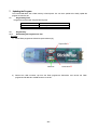
Programming Tools .................................................................................................................................................47
7.2.
Programming.............................................................................................................................................................47
7.2.1.
Downloading the Program to the Tool..............................................................................................................47
7.2.2.
Preparing the Tool..............................................................................................................................................51
7.2.3.
Programming......................................................................................................................................................52
8.
Performance Inspection .............................................................................................................................54
8.1.
Reproducibility..........................................................................................................................................................54
8.2.
Cornerload Error.......................................................................................................................................................54
8.3.
Linearity ......................................................................................................................................................................54
8.4.
Tilt Error ......................................................................................................................................................................54
9.
Problems and Solutions.............................................................................................................................56
9.1.
General Problem Solutions....................................................................................................................................56
9.2.
Error Display..............................................................................................................................................................57
9.2.1.
User Mode Errors...............................................................................................................................................57
9.2.2.
Service Mode Errors..........................................................................................................................................58
9.2.3.
Self check when power is turned on ................................................................................................................58
10.
Troubleshooting.......................................................................................................................................59
10.1.
Display Won't Appear..........................................................................................................................................59
10.2.
Display Not Showing Correctly.........................................................................................................................59
10.3.
Key Operation Does Not Work..........................................................................................................................60
10.4.
Poor Reproducibility............................................................................................................................................61
10.5.
"ERR H" Is Displayed..........................................................................................................................................62
10.6.
When Power is Switched On, Display Stops at "CHE 5" or “Software Version”...................................63
10.7.
When Power is Switched On, Display Stops at "CHE 0".............................................................................64
10.8.
Trouble of Weight Loader...................................................................................................................................65
11.
11.1.
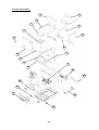
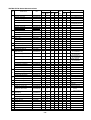
Components List......................................................................................................................................66
TW/TWC,TX/TXC series......................................................................................................................................66
- ii -
11.1.1.
11.1.2.
TW/TWC,TX/TXC exploded view....................................................................................................................66
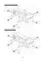
TX/TXC series dedicated jigs ...........................................................................................................................76
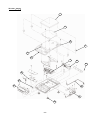
11.2.
TXB Series.............................................................................................................................................................77
11.2.1. TXB exploded view............................................................................................................................................77
11.2.2. TXB Series Maintenance Parts ........................................................................................................................78
11.2.3. TXB series dedicated jigs..................................................................................................................................79
11.3.
TW/TX/TXB Series Shared Jigs and Tools .....................................................................................................79
- iii -
1. Operations for Adjustment
For the general operations method, see the User's Manual for the TW/TX/TXB Series.
1.1.
ROM version information
TX ROM ver.
TX only (except TXC623)
TW/TX-L all model
TW/TX-N(*1) and TW/TX-L all
model
Ver
Ver 1.XX.XX.XX
Ver 2.XX.XX.XX
Ver 3.XX.XX.XX
*1: for Japan only
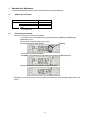
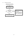
1.2.
Entering the Service Mode
Move from user mode to service mode as follows.
(1) In the user mode mass display state, keep pressing (3-5sec.) [BREAK] and [PRINT] keys.
(2) Release the keys.
(3) Press down on the [CAL] and [->O/T<-] keys.
(4) The password input display appears.
Flashing
Use the arrow keys to input numbers.
Input 00321 as the maintenance mode password, and press the [MENU/Enter] key.
(5) When the password is approved, the service mode opens.
Alternately, you can enter service mode by inputting the maintenance mode command "@SVC=321" from
the PC.
-1-
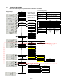
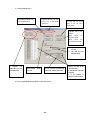
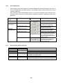
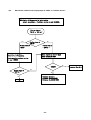
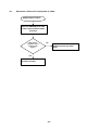
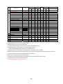
Contents of Service Menu
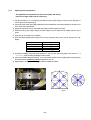
The service mode configuration (menu configuration diagram) is shown below.
(Maintenance Mode)
Display example
※Marking mean going buck to Measure Mode
AD
Error Log
TYPE Display
SHIP Display
Software Version
← If no error has occurred,
"NOERR" is displayed.
Press the → key to display
the last five errors recorded
in the log, in order of
occurrence.
After Ageing
Span(ppm/C)
[Normal Range (guideline)]
Span after aging
0 to ± 3 (TW/TX)
0 to ± 5 (TXB)
ppm/ °C
Span before aging
0 to ± 20 (TW/TX)
0 to ± 80 (TXB)
ppm/ °C
Zero after aging
0.000 to ± 0.200 (TW/TX/TXB)
g/ °C
Zero before aging
0.000 to ± 0.500 (TW/TX/TXB)
g/ °C
Before Ageing
Span(ppm/C)
After Ageing
ZERO Drift(g/C)
Before Ageing
ZERO Drift(g/C)
AD Display
WAD ※
Wad(TW.TX)
1.3.
WAD (TXB)
TAD (TW/TX)(10-30℃)
TAD (TXB)
OAD
LAD
WG
CR
TAD ※
OAD ※
LAD ※
WG ※
CR ※
Weight Loader
old TXC
common TWC/TXC
old TX small pan
common TW/TX small
old TX Large pan
common TW/TX large
Zero
Span
1,100,000-2,000,000
200,000-800,000
700,000-1,400,000
200,000-1,100,000
500,000-900,000
200,000-1,100,000
60,000 - 80,000
2,000,000
3,000,000(600ct)
2,000,000
2,700,000(420g)
1,650,000
2,700,000(4200g)
200,000
26,000 – 40,000
15,000 – 29,000
±10.000
(g)
Only TXB Series
HOME POSITION
Only TW Series
LOAD,UNLOAD
Linear
Adjust Run
Ok?
Setting Weight
Input
Select Type
Type list
Set Shipment
Japan
Not appear when [LOCK] is ON.
SI
EXP
ASIA
TA
Sirial NO. Input
OEM Setting
Lock Setting
NVRAM
UP 5div Input
Input
DOWN 5div Input
Input
ON
Weight Input
Input
Min Input
Input
ON ※
"PRINT" OUTPUT OF RAM DATA
"EDIT" RAM DATA EDIT
Edit Run
"BK.UP" EEPROM -> FLASH
Ok?
"RESTR" FLASH -> EEPROM
Ok?
"INIT" INITIALIZATION OF RAM DATA
Ok?
END
-2-
Weighing
capacity
(g)
Items in the figure framed in thick lines denote execution items, while those framed in thin lines denote menu
items.
Shaded items are not displayed when the setting information lock is on. Use the arrow keys to move between
items.
Key
Explanation
Move
to
an
item
in
a
subordinate
menu.
If
the
menu
item to the left of the arrow has no asterisk mark and is also
→
shaded, pressing the Enter key on that item opens a subordinate menu item. (In other words, if the higher menu
accepts the Enter key even if it has no enable/disable switch, pressing the Enter key opens the subordinate menu.)
To open the menu from the mass display state, use the MENU key instead of the → key.
Return to the item in the higher menu.
←
Move to items in order.
↓
Move to items in reverse order.
↑
* For the release method of setting information lock, see "5.3.1 Releasing the Setting Information Lock".
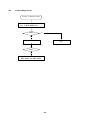
1.4.
Service Mode Functions
Service mode functions are shown below.
Function
Error display
Model name display
Destination display
Software Ver. display
Outline
Displays error codes for errors that have occurred in user
mode.
If no errors have occurred when service mode is opened,
the error display does not appear.
Displays the model name setting.
Displays the destination setting.
Ex.: JPN = Japan
SI = Countries and regions that recognize SI units
only
EXP = Overseas (excluding Southeast Asia)
ASIA = Southeast Asia
TA = Type Approval
Displays the currently mounted software version.
Ex.: 1.00, ##, XX
In principle, 1.00 is the version number for hardware changes
Next, ## is the version number for manuals and other documentation
changes
Finally, XX is the version number for bug fixes and other minor changes
Span temperature coefficient display
Displays the span temperature coefficient for before and
after aging.
Zero drift display
Displays the amount of zero drift before and after aging.
AD
value Mass data (WAD) display
Displays mass data as received from AD converter. (Data
display
subjected to smoothing)
Temperature
data
(TAD) Digitally displays voltage of temperature sensor mounted
display
on UniBloc magnet or load cell.
Temperature-corrected mass Displays WAD mass data subjected to temperature
data (OAD) display
correction. (Data subjected to smoothing)
Linear-corrected mass data Displays OAD mass data subjected to linearity correction.
(LAD) display
Absolute load (WG) display
Displays mass values shown in g units that are subjected
to all correction processing. Displays mass values not
subjected to zero setting or tare weight.
Creep (CR) display (TXB only) Displays WG mass data subjected to creep correction.
Sensitivity calibration
Executes sensitivity calibration using the same operation
as user mode.
Weight
Return to initial position
Internal weight loader system returns to initial position.
Loader check Load and Unload
Internal weight is loaded or unloaded to UNIT ASSY.
(Only TW)
Linearity
Linearity adjustment
Executes the adjustment operation for calculation of the
adjustment
linearity correction coefficient.
Weight value input for linearity Inputs the reference weight value used for linearity
adjustment
adjustment.
-3-
Function
Model selection
Shipping
settings
Unit for Japan
SI unit
Overseas unit
Unit for Asia
Type Approval
Serial No.
Top 5 digits
input
Bottom 5 digits
OEM
On
Weighing capacity
Minimum display
Setting information lock (error check)
NVRAM
Data print
Data edit
Backup
Download
All initialize
END
General
Selection of the model name automatically sets the basic
information for weighing capacity, minimum display, and
reference mass for adjustment.
Set the units users can use, depending on shipping
destination.
Initial setting = Unit for Japan
Input the top 5 digits of serial No.
Input the bottom 5 digits of serial No.
Sets to OEM model.
Changes the weighing capacity.
Changes the minimum display.
Prevents changes to the model, OEM, shipping, and S/N
settings. When the lock is active, all error checks are
enabled.
Outputs data saved in EEPROM to a dedicated printer.
Edits data saved in EEPROM on balance display unit.
Of the data saved in EEPROM, backs up temperature
correction coefficient, linearity correction coefficient, and
model setting status data to a Flash memory.
Writes to EEPROM the data backed up on Flash memory.
Initializes all data saved in EEPROM.
Ends service mode.
-4-
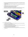
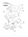
2. Disassembling and Assembling the Balance
2.1.
2.1.1.
TW/TX Series
Precautions
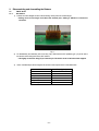
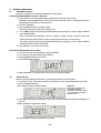
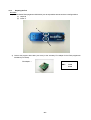
1) Pull the connector straight out when disconnecting. Never pull it out at a bent angle.
* Pulling out at a bent angle could bend the terminal pins, making it difficult to re-insert the
connector.
Fig. 1
2) For disassembly and assembly of the unit Assy TX(1), first insert the OPF positioning pin (J1) as far as the
line set in the lever fixing hole on the OPF surface.
* Lift slightly on the lever Assy (U7) to insert the pin. Be careful not to scratch the elastic support.
3) Use a controlled torque driver to tighten the screws to the torques shown in the table below.
Screw
M2
M2.5
M3 pan head
M3 hexagonal socket head
M4 pan head
M4 hexagonal socket head
-5-
Torque [kgf-cm]
1
2.5
9
15
18
30
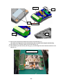
2.1.2.
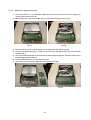
Inspecting the Balance Interior (Removing the Case and Pan Support)
[Disassembly]
1) Detach the AC adaptor, then:
[Carat/small pan only] Remove the pan (6), pan support (4), windbreak ring (7) (carat only), and sole plate
(8).
[Large pan only] Remove the pan (6), pan support cap (5), and sole plate (8).
2) [Carat/small pan only] Remove the knob (C10) on the inside of the ceiling glass set (C5), and slide the
ceiling glass set (C5) backward to remove.
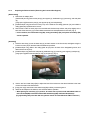
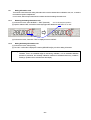
3) Remove the P4 M4×12 screw (22) on the back side of the balance top surface, and pull up slightly on the
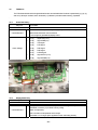
back side of the case Assy (3), so that it slides toward the front and separates from the base. (Fig. 2)
* In this condition, the main board Assy (B2), analog board Assy (B3), and power board Assy (B4)
can be inspected.
[Assembly]
1) Place the case Assy (3) over the base Assy (2) so that it catches on the front hooks, and tighten using the
P4 M4×12 screw (22) on the back side of the balance top surface.
2) [Carat/small pan only] Slide in the ceiling glass set (C5) from the back of the designated grooves, and
attach the inner knob (C10).
3) [Carat/small pan only] Mount the sole plate (8), windbreak ring (7) (carat only), pan support (4) and pan (6).
[Large pan only] Mount the sole plate (8), cap (5), and pan (6). (Fig. 2)
Fig. 2
4) Use the two front caster Assys (B6) to adjust the level of the balance so that the air bubbles in the level
come to the center of the framed area.
5) [Large pan only] Lower the two rear caster Assys (B6) until they contact the ground.
6) Attach the AC adaptor to the balance, and check the balance operation.
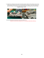
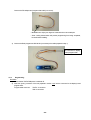
* When placing the case Assy (3) in position, be careful not to pinch the ILS 10S-10S-300 cable or
ILS 11S-11S-440(B9) connected between Main board Assys(B2) and Power Board Assys
(Fig. 3)(Including later procedure after this, photo A shows old TX and B shows TW/TX common.)
-6-
Fig. 3-A
2.1.3.
Replacing Components
2.1.3.1.
Replacing the Front Glass (C8)
Fig. 3-B
1) Detach the AC adaptor, and remove the pan (6), pan support (4), windbreak ring (7) (carat only), and sole
plate (8).
2) Remove the knobs (C10) on the inside of the ceiling glass set (C5) and side glass sets (C6, C7) and slide
the ceiling glass set (C5) and side glass sets (C6, C7) backward to remove.
3) Remove the knobs (C10) in two locations on the front.
4) Tilt the rear surface of the case roof cover (C4) and remove it. (Fig. 4)
5) Loosen the P4 M4×12 screw (22) holding the case roof (C3), and remove the case roof (C3).
6) Position the front glass (C8) on the back of the case (C1) front groove, and pull upward to remove the front
glass (C8). (Fig. 5)
7) Follow steps 1) to 6) in reverse to attach the new front glass (C8).
C
Top
A
Length: A < B,C > D
D
B
Fig. 4
Fig. 5
-7-
2.1.3.2.
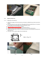
Replacing the Main Board Assy (B2)
1) Use the procedure in "2.1.2 Inspecting the Balance Interior (Removing the Case and Pan Support)" to
remove as far as the case Assy (3).
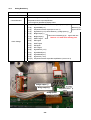
2) Remove the three P4 M4×8 screws (B22) fixing the main board Assy (B2) in place. (Fig.6)
Fig.6-A
Fig.6-B
3) Disconnect the J2,J3 and J4 connectors that are connected to the main board Assy (B2).
4) Place the main board Assy (B2) in a location on the right side of the balance that is free of dirt and static
electricity. (Fig. 7)
5) Remove the EEPROM located on the back side the main board Assy (B2) from the socket, taking care to
avoid damaging the EEPROM feet.
6) Mount the EEPROM on the new main board Assy (B2).
7) Follow steps 1) to 3) in reverse to attach the new main board Assy (B2).
Fig.7-A
Fig.7-B
-8-
2.1.3.3.
Replacing the Analog Board Assy (B3)
1) Use the same procedure as steps 1) to 3) in "2.1.3.2 Replacing the Main Board Assy (B2)" to remove as far
as the main board Assy (B2).
2) [Large pan only] Loosen the two P4 M4×8 screw (22), and remove the large unit cover (9). (Fig.8)
3) [Large pan only] Insert the OPF positioning pin (J1) as far as the line set in the lever fixing hole on the OPF
surface.
4) [Large pan only] Loosen the two P4 M4×14 bolt (23), and remove the large pan support Assy (4). (Fig.9)
Fig.8
Fig.9
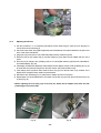
5) Disconnect the J1,J2 and J3 connectors that are connected to the analog board Assy (B3) and
loosen and remove the three P4 M4×8 screws (B22) fixing the cover plate,analog (13) . (Fig. 10)
6) Loosen and remove the two P4 M4×8 screws (B22) fixing the analog board Assy (B3) in place. (Fig. 11)
Fig.10
Fig.11
-9-
7) Follow steps 1) to 6) in reverse to attach the new analog board Assy (B3).
* During assembly, use the CS-5 clip (B26) to securely hold the cables for Main board Assy(B2),the
weight loader Assy(27) (TW only) and Unit assy,TX(1) downward so that the large pan support
Assy (4) and the cables do not contact. (Fig. 12)
Fig.12-A
Fig.12-B1
Fig.12-B2
Fig.12-B3
*Attach pan support Assy (4) using Unit assy locating jig(J2) (Fig.13)
Fig.13
- 10 -
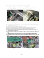
2.1.3.4.
Replacing the Power Board Assy (B4)
1) Use the procedure in "2.1.2 Inspecting the Balance Interior (Removing the Case and Pan Support)" to
remove as far as the case Assy (3).
2) [Large pan only] Loosen the two P4 M4×8 screw (22), and remove the large unit cover (9).
3) [Large pan only] Insert the OPF positioning pin (J1) as far as the line set in the lever fixing hole on the OPF
surface.
4) [Large pan only] Loosen the two P4 M4×14 bolt (23), and remove the large pan support Assy (4).
5) Remove the two screws,D-sub (B25) holding the power board Assy (B4) and I/F panel (B5) in place.
(Fig.14)
6) Loosen the two M3×6 button screws (B23) and remove the I/F panel (B5). (Fig. 15)
Fig.14
Fig.15
7) [Common design for TW/TX only] Open the cable clamp for ILS 11S-11S-440(B9).
8) Loosen the two P4 M4×8 screws (B22) fixing the power board Assy (B4) in place, and remove together
with the CS-5 clip (B26). (Fig. 16)
* The power board Assy (B4) can be removed by pulling upward at an angle, as shown in Fig. 17.
Fig.16
Fig.17
- 11 -
9) Disconnect the J4 connector that is connected to the power board Assy (B4).
10) Follow steps 1) to 9) in reverse to attach the new power board Assy (B4).
* During assembly, use the cable clamp and the CS-5 clip (B26) to securely hold the cables for
Power board Assy(B4) downward so that the large pan support Assy (4) and the cables do not
contact. (Fig. 16 and 18)
Fig.18-A
2.1.3.5.
Fig.18-B
Replacing the Detector Assy (U11)
1) Use the procedure in "2.1.2 Inspecting the Balance Interior (Removing the Case and Pan Support)" to
remove as far as the case Assy (3).
2) Loosen the P4 M4×8 screw (22), and remove the unit cover (9).
3) Insert the OPF positioning pin (J1) as far as the line set in the lever fixing hole on the OPF surface.
4) [Large pan only] Loosen the P4 M4×14 bolt (23), and remove the large pan support Assy (4).
5) Remove the soldering for the temperature sensor cable connected to the detector Assy (U11). (Fig. 19)
* TP1: Yellow wire, TP2: Blue wire
6) Disconnect the J25 connector for the ILS-7S-7S-130 cable (U19) that is connected to the detector Assy
(U11).
* When removing, be careful not to touch the lever Assy (U7) and scratch the elastic support.
7) Loosen and remove the P3 M3×10 socket head bolt (U53) holding the detector Assy (U11) in place. (Fig.
20)
Fig.19
Fig.20
- 12 -
8) Follow steps 4) to 7) in reverse to attach the new detector Assy (U11).
9) Adjust the detector height by following "4.1.1 Adjusting the Height of the Detector Assy (U11)".
10) Follow steps 1) to 4) in reverse to restore the original status.
* Clamp to securely hold cable,ILS 7S-7S-130(U19) with short loose length so that the
Assy,Detector (U11) do not receive upward or downward force by it. (Fig. 21)
* [TW only] Clamp to securely hold cable,ILS 7S-7S-130(U19) and wires for the temp.sensor
outside of Magnet frame so that the weight lever for Unit assy,TX (1) and the cables do not
contact. (Fig. 22)
Fig.21
2.1.3.6.
Fig.22
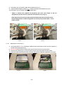
Replacing the TX Unit Assy (1)
1) Use the procedure in "2.1.2 Inspecting the Balance Interior (Removing the Case and Pan Support)" to
remove as far as the case Assy (3).
2) [Non-CE only]Loosen the two P4 M4×8 screw (22), and remove the unit cover (9). (Fig.23)
3) Insert the OPF positioning pin (J1) as far as the line set in the lever fixing hole on the OPF surface.
4) [Large pan only] Loosen the two P4 M4×14 bolt (23), and remove the large pan support Assy (4). (Fig.24)
Fig.23
Fig.24
- 13 -
5) [TW only] Loosen the two P4 M3×6 screw (30), and remove the leaf supring,weight loaderr (29) and the
weight(28). (Fig.25)
6) Disconnect the J2 and J3 connectors that are connected to the analog board Assy (B3).
7) Loosen and remove the four P4 M4×14 socket head bolts (23) fixing the TX unit Assy (1) in place. (Fig. 26)
* When lifting up the TX unit Assy (1), do not grab the parallel guide or movable column.
Fig.25
Fig.26
8) Follow steps 4) to 7) in reverse to attach the new TX unit Assy (1).
* During assembly, use the CS-5 clip (B26) to securely hold the cables for Unit Assy,TX(1)
downward so that the large pan support Assy (4) and the cables do not contact. (Fig. 27)
9) Check tilt error and cornerload error by following "4.1.2 Adjusting the Tilt Error" and "4.1.3 Adjusting the
Cornerload Error". Adjust them,if they are out of torelance.
10) Follow steps 1) to 3) in reverse to restore the original status.
11) Input EEPROM data of attached with Unit assy.(Refer to 4.1)
Address No. 004-05A (Temp. data)
Fig.27
- 14 -
2.1.3.7. Replacing the Weight loader Assy (27)
1) Use the procedure in "2.1.3.6 Replacing the TX Unit Assy (1)" to remove the TX unit Assy (1).
2) Open the CS-5 clip for the cables of the weight loader assy(27) and disconnect the connector that are
connected to the main board Assy (B2)
3) Loosen and remove the three P4 M3×6 screws (30) fixing the weight loader Assy (27) in place. (Fig. 28)
4) Follow steps 2) to 3) in reverse to attach the new weight loader Assy (B3)
* During assembly, use the CS-5 clip (B26) to securely hold the cable for the weight loader
Assy(27) (TW only) downward so that the large pan support Assy (4) and the cables do not
contact. (Fig. 12)
Fig.28
Fig.29
5)
Attach the AC adaptor and turn on the power of balance and enter the service mode and
select LD.ULD and stop the arm weight loader on the lower position.
6) Insert Jig bloc,TW weight arm(J9) between the frame and the arm of weight loader Assy(27) to be the arm
on the level. (fig.30)
7) Tighten the four P4 M4×14 socket head bolts (23) temporarily fixing the TX unit Assy (1) in place.
8) Set location pin,weight loader(J8) on the dint of the arm of the weight loader Assy(27) and the weight
lever of the unit Assy,TX(1) and tighten the bolts for TX unit Assy(1) and screws for weight loader Assy(27)
(fig.31)
Fig.30
Fig.31
- 15 -
2.1.3.8.
Replacing the Force Coil Assy (L1)
1) Use the procedure in "2.1.3.6 Replacing the TX Unit Assy (1)" to remove the TX unit Assy (1).
2) Remove the soldering on the lever Assy (U7) side of the two Pt-Ni bands (U17).
* Do not break or damage the PT-Ni bands.
3) Loosen and remove the two P3 M3×14 socket head bolts (U58) fixing the detector frame (U10) in place.
(Fig. 32)
4) Loosen the four M2.5×6 screws (U54) fixing the four magnet lids (U16) in place, and slide the magnet lids
(U16) in the horizontal direction to remove. (Fig. 33)
Fig. 32
Fig. 33
5) Remove the four P3 M3×14 socket head bolts (58) fixing the lever Assy (U7) in place, and remove the lever
Assy (U7) from above.
6) Remove the soldering from the twisted wire (L7) of the force coil Assy (L1) terminal board.
7) Loosen and remove the M2.5×6 screw (L5) and PB SPG M2.6 washer (L6) fixing the force coil Assy (L1) in
place.
8) Use an M2.5×6 screw (L5) to temporarily fix the new force coil Assy (L1) to the lever Assy (U7), and solder
the twisted wire (U7) to the force coil Assy (1). (Fig. 34)
* As viewed from lever Assy (U7) mounting side, Left side: Yellow wire, Right side: Blue wire
9) Insert the lever Assy (U7) from the top of the unit, and use four P3 M3×14 socket head bolts (58) to
temporarily fix it in place.
10) Pass the slit of the lever stopper (U15) attached to the detector frame (U10), and the pinhole of the stopper
plate (U14), through the lever Assy (U7), and use two P3 M3×14 socket head bolts (58) to temporarily fix
the frame detector (U7) in place.
11) Insert the gap setting shim (J3) between the lower edge of the lever shutter on the edge of the lever Assy
(U7) and the lower edge of the slit in the lever stopper (U15), for positioning, and use four P3 M3×14 socket
head bolts (58) to fix in place. (Fig. 35)
12) Remove the temporarily fixed detector frame (U7).
- 16 -
Fig. 34
Fig. 35
13) Looking at the TX unit Assy (1) from the top, tighten the force coil Assy (L1) at the position where the center
of the magnet Assy (U9) aligns with the center of the force coil Assy (L1).
14) Slide in and attach the four magnet lids (U16) from the horizontal direction and use four M2.5×6 screws
(U54) to tighten in place.
15) Again, pass the slit of the lever stopper (U15) attached to the detector frame (U10), and the pinhole of the
stopper plate (U14), through the lever Assy (U7), and use two P3 M3×14 socket head bolts (58) to tighten
the frame detector (U7) in place.
16) Solder the lever Assy (U7) side of the two Pt-Ni bands (U17).
* When soldering, do not twist or break the Pt-Ni bands.
17) Adjust the stopper plate (U14) to a position aligned with the center of the lever Assy (U7) pin, and use an
M3×6 socket head bolt (U57) and M3 washer (U56) to tighten.(Fig. 36)
18) Remove the OPF positioning pin (J1) from the TX unit Assy (1), then gently shake the TX unit Assy (1) to
check that the lever Assy (U7) moves smoothly up and down and that a clear sound is heard when it strikes
the lever stopper (U15). If it does, assembly of the TX unit Assy (1) is complete.
19) Follow steps 4) to 6) of "2.1.3.6 Replacing the TX Unit Assy (1)" in reverse to attach the new TX unit Assy
(1).
20) Adjust tilt error and cornerload error by following "4.1.2 Adjusting the Tilt Error" and "4.1.3 Adjusting the
Cornerload Error".
21) Follow steps 1) to 3) of "2.1.3.6 Replacing the TX Unit Assy (1)" in reverse to restore the original status.
Fig. 36
- 17 -
2.2.
2.2.1.
TXB Series
Precautions
1) Pull the connector straight out when disconnecting. Never pull it out at a bent angle.
* Pulling out at a bent angle could bend the terminal pins, making it difficult to re-insert the
connector.
Fig. 1
2) When handling the load cell Assy, be careful not to apply excessive force.
* The cell could be damaged.
3) Use a controlled torque driver to tighten the screws to the torques shown in the table below.
Screw
M2
M2.5
M3 pan head
M3 hexagonal socket head
M4 pan head
M4 hexagonal socket head
- 18 -
Torque [kgf-cm]
1
2.5
9
15
18
30
2.2.2.
Inspecting the Balance Interior (Removing the Case and Pan Support)
[Disassembly]
1) Detach the AC adaptor, and remove the pan (1), pan support (2), and windbreak ring (3). To remove the
windbreak ring (3), rotate it clockwise as viewed from above.
(1) Pan
(2) Pan support
(3) Windbreak ring
Fig. 1 Large Pan Model
Fig. 2 Small Pan Model
2) Remove the two M4×10 pan head screws (21), and remove the metal plate (4) and ring spacer (5). Then,
remove the two M4×8 sems screws (22).
(21) M4×10
(21)
(4) Metal plate
(5) Ring spacer
(22)
(22) M4×8
Ring spacer positioning
Fig. 3 Large Pan Model
Fig. 4 Small Pan Model
- 19 -
3) Lift up the upper case (6) from the back, and disengage from the hooks at the front of the lower case (7).
(6) Upper case
(7) Lower case
Back: Two hooks
@A
@B
@B
@A
Fig. 5 Removing the Upper Case
* In this condition, the main board Assy (B1), analog board Assy (B2), and power board Assy (B3)
can be inspected.
[Assembly]
1) See Fig. 5 to insert the two slits on the front of the upper case (6) into the lower case (7) hooks, and
cover the back of the upper case (6) over the lower case (7).
2) Attach M4×8 sems screws (22) in two locations.
3) Mount the ring spacer (5) to align with the upper case (6) ring spacer positioning projection.
From above, align the metal plate (4) with the pan head screw hole on the ring spacer (5), and attach the
M4×10 pan head screw (21).
4) Attach the windbreak ring (3), pan support (2), and pan (1), in that order.
5) Use the two front level adjustment feet (8) to adjust the level of the balance so that the air bubbles in the
level come to the center of the framed area.
6) [Large pan only] Lower the two rear level adjustment feet (8) until they contact the ground.
7) Attach the AC adaptor to the balance, and check the balance operation.
- 20 -
2.2.3.
Replacing Components
(12) Load cell ASSY
C4
(10) Analog board ASSY
(9) Main board ASSY
C1
(13) Cable 9-9
C3
(11) Power board ASSY
C2
C5
(14) Cable 10-10
C6
(15) Battery cable
2.2.3.1. Replacing the Main Board Assy (9)
1) Use the procedure in "2.2.2 Inspecting the Balance Interior (Removing the Case and Pan Support)" to
remove as far as the upper case (6).
2) Disconnect the connector (C1) for cable 9-9 (13) and the connector (C2) for cable 10-10 (14) that are
connected to the main board Assy (9).
3) Remove the three P4 M4×8 screws (23) fixing the main board Assy (9) in place.
4) Place the main board (9) in a location that is free of dirt and static electricity.
5) Remove the EEPROM located on the back side the main board Assy (9) from the socket, taking care to
avoid damaging the EEPROM feet.
6) Mount the EEPROM on the new main board Assy (9).
7) Follow steps 1) to 3) in reverse to attach the new main board Assy (9).
2.2.3.2. Replacing the Analog Board Assy (10)
1) Use the procedure in "2.2.2 Inspecting the Balance Interior (Removing the Case and Pan Support)" to
remove as far as the upper case Assy (6).
2) Disconnect the connector (C3) for cable 9-9 (13) that is connected to the analog board Assy (10).
3) Remove the cell Assy (12) flexible board (C4).
* Be careful not to damage the cell Assy.
4) Loosen and remove the four P4 M3×8 screws (23) fixing the analog board Assy (10) in place.
5) Follow steps 1) to 6) in reverse to attach the new analog board Assy (10).
2.2.3.3. Replacing the Power Board Assy (11)
1) Use the procedure in "2.2.2 Inspecting the Balance Interior (Removing the Case and Pan Support)" to
remove as far as the upper case Assy (6).
2) Disconnect the connector (C5) for cable 10-10 (14), and the connector (C6) for the battery cable (15) that
are connected to the power board Assy (11).
3) Loosen the two M3×6 truss screws (25) fixing the back plate (16) in place.
4) Remove the two M3×8 sems screws (23) fixing the power board Assy (11) in place.
5) Slide the back plate (16) upward, and remove the back plate (16) and power board Assy (11).
- 21 -
6) Remove the two CDHWE101S00 screws (24) fixing the power board Assy (11) and back plate (16) in place.
7) Temporarily tighten the two CDHWE101S00 screws (24) fixing the new power board Assy (11) and back
plate (16) in place.
8) Slide the back plate (16) down, and set the back plate (16) so that it is held down by the M3×6 truss screw
(25).
9) Use two M3×8 sems screws (23) to fix the power board Assy (11) in place.
10) Use two M3×6 truss screws (25) to fix the back plate (16) in place.
11) Tighten the two loosely tightened CDHWE101S00 screws (24).
12) Disconnect the connector for cable ILS 10S-10S-270 (B9) that is connected to the power board Assy (B4).
13) Insert the connector (C5) for cable 10-10 (14) and the connector (C6) for the battery cable (15).
(16) Back plate
(23)
(25)
(24)
2.2.3.4. Replacing the Load Cell Assy (12)
1) Use the procedure in "2.2.2 Inspecting the Balance Interior (Removing the Case and Pan Support)" to
remove as far as the upper case Assy (6).
2) Disconnect the connector (C6) for the battery cable (15).
3) Remove the four level adjustment feet (8) on the back of the main body (for the large pan model; the small
pan model has two feet), and the two M4×8 sems screws (22).
* Be careful not to apply force to the load cell Assy.
4) Remove the two M4×8 sems screws (22) fixing the base Assy (17) in place.
5) While removing the connector (C6) from the base Assy (17) hole, lift up the back plate (16) to remove the
base Assy (17).
- 22 -
Cable hole
(22)
(22)
Front hooks
@C
@C
6) Remove the hexagonal socket head bolt on the back of the base Assy (17).
* Be careful not to apply force to the load cell Assy. Also be careful not to drop the load cell Assy.
7) Follow steps 2) to 5) in reverse to attach the new load cell Assy (12).
8) While positioning the load cell Assy with the jig (31), use the hexagonal socket head bolt to attach the load
cell Assy (12).
(31) Cell positioning jig
- 23 -
9) Adjust the four displacement stop screws for the load cell Assy. Raise the screws until they touch the pan
support projection, and then lower them by turning backward by 270 degrees. Confirm that the gap jig t=0.4
(32) can be inserted but the gap jig t=0.6 (32) cannot be inserted. Use Loktite (26) to fix the screws in place.
Adjustment range: 0.5 mm
10) Input EEPROM data of attached with load cell assy. (Refer to 4.2)
Address No. 004-05A (Temp. data) and No. 14A-158 (Creep coefficient data. TXB only)
- 24 -
3. Checking the Electronic Board
3.1.
TW/TX Series
The TW/TX Series boards and their signal allocations are summarized below. Numbers in parenthesis ((1), (2),
(3), and so on) show pin numbers, and a checkmark (9) indicates a point that needs checking, if possible.
3.1.1.
Main Board Assy (B2)
Assy P/N
321-64553-03(TW/TWC, TX/TXC common), -01(TX, TXC323L), -14(TXC623L)
Board P/N
321-64555
CPU (Metric data calculation, LCD control, key switch control)
Circuits Mounted
EEPROM, connector (J1) for Flash memory writing
Main clock (20 MHz), generates +5 V for logics
Motor driver for weight loader
3.1.2.
Analog Board Assy (B3)
Assy P/N
321-64556-11 (TW/TX small pan), -12 (TW/TX large pan), -14 (TWC/TXC)
Board P/N
321-64558
Mechanical sensor PID control (feedback)
Circuits Mounted
Measurement system (A/D converter) circuit and reference power generation circuit
Magnet temperature correction and measurement circuit
TPG
Signal GND (0 V)
TP1
Pre-amp control signal output; 0 V at feedback
TP2
Coil current control voltage
9
TP3
Output resistance terminal voltage (approx. 0.6 to 2.3 V)
9
J2 (1)
Beam sensor light emission diode positive voltage approx –5.2 V
9
J2 (2)
Beam sensor light emission diode negative voltage approx –6.8 V
9
J2 (3)
Magnet temperature sensor output voltage approx. 0.6 V
J2 (4)
Signal GND (0 V)
J2 (5)
Beam sensor reception diode output; 0 V at feedback
J2 (6)
Signal GND (0 V)
J2 (7)
Beam sensor reception diode output; 0 V at feedback
J1 (1)
Signal GND (0 V)
9
J1 (2)
Analog system power approx. -12 V
9
J1 (3)
Analog system power approx. +12 V
J1 (4)
Temperature A/D digital signal
J1 (5)
Temperature A/D digital signal
J1 (6)
Weight A/D digital signal
J1 (7)
Weight A/D digital signal
J1 (8)
Weight A/D digital signal
J1 (9)
Weight A/D digital signal
9
Check Voltage
(connecting Assy,
Detector)
- 25 -
3.1.3.
Power Board Assy (B4)
Assy P/N
321-64550
Board P/N
321-64552
Smoothes out AC adaptor input (DC 12 V/1 A), generates ±12 V and +5 V for
communications
DATA I/O and RS-232C communications
Circuits Mounted
J4 (1)
Signal GND (0 V)
J4 (2)
Signal GND (0 V)
9
J4 (3)
Supplies power to other circuits, approx. +12 V
9
J4 (4)
Supplies power to other circuits, approx. -12 V
J4 (5)
AC adaptor (external battery) power check voltage approx. +3.8 V
J4 (6)
DTR signal
J4 (7)
TXD signal
J4 (8)
RXD signal
J4 (9)
DSR signal
Check Voltage
J4 (10) DTR/P signal
9
J4 (11)
Supplies power to other circuits, approx. +12 V
- 26 -
3.2.
TXB Series
The TXB Series boards and their signal allocations are summarized below. Numbers in parenthesis ((1), (2), (3),
and so on) show pin numbers, and a checkmark (9) indicates a point that needs checking, if possible.
.
3.2.1.
Power Board Assy
Assy P/N
321-63855
Board P/N
321-63857
Smoothes out AC adaptor and dry battery input (DC 12 V/1A, DC 9 V)
Circuits Mounted
DATA I/O and RS-232C communications
+5 V for logics is generated by Display board.
9
J5 (1)
Signal VIC(+12 V)
9
J5 (2)
Signal GND (0 V)
J5 (3)
TXD signal
J5 (4)
DTR signal
J5 (5)
RXD signal
J5 (6)
DSR signal
J5 (7)
DTR/P signal
9
J5 (8)
Signal DVCC (+5 V)
9
J5 (9)
Signal DGND (0 V)
Check Voltage
3.2.2.
Display Board Assy
Assy P/N
321-63850
Board P/N
321-63852
CPU (Metric data calculation, LCD, key switch, and back light control)
EEPROM, connector (J3) for Flash memory writing
Circuits Mounted
Main clock (20 MHz)
A/D conversion for temperature sensor output
Generates +5 V for logics (Also supplied to Power and Analog boards)
- 27 -
3.2.3.
Analog Board Assy
Assy P/N
321-63845
Board P/N
321-63847
A/D converter, generates analog +5 V
Circuits Mounted
Temperature sensor output amplification
9
+5 V for logics is generated by Display board.
J1 (1) Signal AGND (0 V): A/DC reference (-), bridge power (-)
J1 (2)
Signal AGND (0 V)
Between (1)-(4)
J1 (3)
Temperature sensor output (0.57 to 0.67 V)
Approx 420 ohm
9
J1 (4)
9
J1 (5)
9
J1 (6)
J2 (1)
Signal AVCC (+5 V): A/DC reference (+), bridge power (+)
Bridge output (+)
Zero to 6 mV between (5)-(6) approx 350 ohm
Bridge output (-)
Remove “J1” cable when checking ohm.
RESET signal
J2 (2)
RDY signal
J2 (3)
DOUT signal
J2 (4)
DIN signal
J2 (5)
SCLK signal
9
J2 (6)
Signal DVCC (+5 V)
9
J2 (7)
Signal DGND (0 V)
J2 (8)
Signal DGND (0 V)
9
J2 (9)
Signal VCC (+12 V)
9
J2 (10) Temperature sensor output after amplification (1.02 to 2.87 V)
Check Voltage
Bridge output (-)
Bridge output (+)
Bridge power
- 28 -
Temperature sensor
output
4. Hardware Adjustment
4.1.
TW/TX Series
When replacing the following components, balance performance may be altered. After replacement, check the
performance and make adjustments if necessary.
Service
Adjustments required
Reference
1
2
3
4
5
6
7
8
Detector
Assy height
adjustment
Tilt
error
adjustment
SPAN
Temerature
coef Write
Linearity
adjustment
Calibration
(*4)
(P-CAL)
Calibration
(I-CAL/E-CA
L)
Error
log
reset
*3)
EEPROM
Data Backup
Unit Assy
replacement
Force coil
Assy
replacement
Detector
Assy
replacement
Analog
board
Assy
replacement
Main
board
Assy
replacement
Weight
loader
Assy
replacement
ROM
Version
Up
2.1.3.6
2.1.3.7
2.1.3.5
2.1.3.3
2.1.3.2
2.1.3.7
7.2
Cornerload
error
adjustment
4.1.3
Digital
Multi–meter
(DC +/-5 V)
Check wire
set
9
4.1.1
9
4.1.2
Tools
required
9
6.2
9 *2)
9 *1)
5.5
9
9
9
9
9
Standard
weight
5.6
9
9
9
9
9
Standard
weight
5.7
9
9
9
9
9
Standard
weight
6.2
9
9
9
9
9
9
9
9
6.3
9
9
9
9
9
9
9
9
9
*1) When the main board Assy (B2) has been replaced, mount the EEPROM from the previous main board Assy
(B2).
*2) When the TX unit Assy (1) has been replaced, input the attached EEPROM data (Address No. 004 – 05A).
*3) All of the EEPROM data of address No. 288 – 28D are set to “0”(zero).
*4) TW series only
4.1.1.
Adjusting the Height of the Detector Assy (U11)
1) With the ILS 2S-90 cable (U20) connector that is connected to the analog board Assy (B3) disconnected,
attach the AC adaptor and turn on the power.
2) Connect the tester terminals to the analog board Assy (B3) TP1 (+) and TPG (-).
3) Slightly loosen the P3 M3×10 socket head bolt (U53) tightening the detector Assy (U11), then lightly raise or
lower the lever Assy (U7) until it contacts the lever stoppers (U15). Adjust the height of the detector Assy
(U11) so that the tester display changes between positive and negative values within a range of ±25%.
* If the digital multimeter display stays negative (-) when the lever Assy (U7) is raised or lowered,
lower the detector Assy (U11). If it stays positive (+), raise the detector Assy (U11).
4) If adjustment is successful, tighten the P3 M3×10 socket head bolt (U53). (Fig. 37)
5) Disconnect the tester terminals from the TP1 and TPG pins of the analog board Assy (B3).
6) Detach the AC adaptor, and connect the ILS 2S-90 cable (U20) connector to the analog board Assy (B3).
- 29 -
Fig. 37
4.1.2.
Adjusting the Tilt Error
1) Use the procedure in "2.1.2 Inspecting the Balance Interior (Removing the Case and Pan Support)" to
remove as far as the case Assy (3).
2) Use the two front caster Assys (B6) to adjust the level of the balance so that the air bubbles in the level come
to the center of the framed area.
3) [Large pan only] Lower the two rear caster Assys (B6) until they contact the ground.
4) Attach the pan (6), pan support cap (5), and pan support (4), then attach the AC adaptor and turn on the
power.
5) Press any key to change to the "g" display, insert a 1 mm thick plate under the right front foot of the balance,
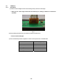
and read the display. (Fig. 38)
6) If the display is outside the adjustment criteria, detach the AC adaptor, insert the OPF positioning pin (J1) as
far as the line set in the lever fixing hole on the OPF surface, and loosen the M3 nut (L9).
7) If the display shows a positive value, rotate the lever Assy (U7) P4 M3×25 screw (L12) clockwise. If the
display shows a negative value, rotate it counterclockwise.
8) Remove the OPF positioning pin (J1), attach the AC adaptor, and turn on the power.
9) Repeat steps 5) to 8) until adjustment is successful. Use the M3 nut (L9) to lock the P4 M3×25 screw (L12)
in place. (Fig. 39)
* Before adjusting the lever Assy (U7) screw and nut, detach the AC adaptor and insert the OPF
positioning pin (J1) into the OPF.
Fig. 38
Fig. 39
- 30 -
4.1.3.
Adjusting the Cornerload Error
* This adjustment is only effective for minor errors (within ±30 counts).
If the error is larger, replace the TX unit Assy (1).
1) Use the procedure in "2.1.2 Inspecting the Balance Interior (Removing the Case and Pan Support)" to
remove as far as the case Assy (3).
2) Use the two front caster Assys (B6) to adjust the level of the balance so that the air bubbles in the level come
to the center of the framed area.
3) [Large pan only] Lower the two rear caster Assys (B6) until they contact the ground.
4) Attach the pan (6), pan support cap (5), and pan support (4), then attach the AC adaptor and turn on the
power.
5) Press any key to change to the "g" display.
6) Place the following adjustment weight on the pan (6), and press the [->0/T<-] key to change to the "0g"
display.
Model
TWC/TXC323L (Carat)
TWC/TXC623L (Carat)
TW/TX (Small pan)
TW/TX (Large pan)
Weight
30[ g]
50[ g]
150 [g]
1,500 [g]
7) First place the weight on the pan center (position 1 in Fig. 40). Then move the weight in the order of 2 → 3
→ 4 → 5 → 1, while recording the display at each position.
8) Use the cornerload adjustment tools (J4, J5) to cut the strain generator of the parallel guide corresponding to
the position where a positive (+) value was displayed. (Fig. 41)
9) Repeat steps 7) and 8) until the result falls within the adjustment criteria.
5
4
5
4
5
1
1
2
3
2
2
Fig. 40
3
Fig. 41
- 31 -
4
3
4.2.
TXB Series
When replacing the following components, balance performance may be altered. After replacement, check the
performance and make adjustments if necessary.
Adjustments required
Service
Reference
1
2
3
4
the
Cornerload
Error
adjustment
the
four
displacement
stop screws for
the load cell
Assy Ad
Coef.
data
Writing
to
EEPROM
Linearity
adjustment
Main Board
Assy(9)
replacement
Analog Board
Assy (10)
replacement
Power Board
Assy (11)
replacement
ROM
Version
Up
Load Cell Assy
(12)
replacement
2.2.3.1
2.2.3.2
2.2.3.3
7.2
2.2.3.4
4.2.1
9
2.2.3.4
8)
9
6.2
9 *1)
Tools required
9 *2)
5.5
9
9
Standard weight
9
9
Standard weight
5
Calibration
(E-CAL)
5.6
6
Error log reset
*3)
6.2
9
9
9
9
9
7
EEPROM
Data Backup
6.3
9
9
9
9
9
*1) When the main board Assy (9) has been replaced, mount the EEPROM from the previous main board Assy(9).
*2) When the load cell Assy (1) has been replaced, input the attached EEPROM data.
Address No. 004 – 05A (Temperature coefficient data) and 14A – 158(Creep coefficient data. TXB only)
*3) All of the EEPROM data of address No. 288 – 28D are set to “0”(zero).
- 32 -
4.2.1.
Adjusting ZERO balance of load cell
It can adjust zero balance of load cell by length of AD wire when too changing zero balance. It need digital
multi-meter and AD wire for adjustment.
1) Check “WAD” of no loading(zero gram condition) and within from “60,000” to “80,000” counts.
2) Input WAD value to the EXCEL file(adjustment software).
Zero Adjustment Sheet for TXB Load cell
Adjustment ZERO Wad value
ZERO WAD is over target -> Insert the Advance wire to (A) ZERO WAD is under target -> Insert the Advance wire to
0.3 Advance wire:10000count/1cm
Target value:60000 - 80000(set actual pan and pan supporter)
S/N
Zero AD value
(befor adjustment)
D5XXXXXXXX
54500
Zero AD value
(after adjustment)
Length of AD wire
Result
--->
-
B
-
1.6cm
-
64200
Judgement
OK
-
3) Confirm AD wire attaching condition, A position, B position or non.
4) Adjust AD wire length by referring below table.
Attaching AD wire position
Result
A
Non
A
B
Attach
Add
Cut
B
Attach
Cut
Add
5) Set pan and pan supporter and check WAD value again.
6) Input WAD value “After adjustment” column. Appearing “NG” in the “Judgment” column, try AD wire
length adjustment again.
- 33 -
4.2.2.
Adjusting the Corner load Error
* This adjustment is only effective for minor errors (within ±30 counts).
If the error is larger, replace the TXB unit Assy (1).
1) Use the procedure in "2.2.2 Inspecting the Balance Interior (Removing the Case and Pan Support)" to
remove as far as the case Assy (3).
2) Use the two front level adjustment feet (8) to adjust the level of the balance so that the air bubbles in the
level come to the center of the framed area.
3) [Large pan only] Lower the two rear level adjustment feet (8) until they contact the ground.
4) Mount the pan (1) and pan support (2), attach the AC adaptor, and turn on the power.
5) Press any key to change to the "g" display.
6) Place the approx half of capacity of weight on the pan (1), and press the [->0/T<-] key to change to the "0g"
display.
7) First place the weight on the pan center (position (1) in Figure below).Then move the weight in the order of
(2) → (3) → (4) → (5) → (1), while recording the display at each position.
8) Use the corner load adjustment tool (34) to cut the strain generator corresponding to the position where a
negative(-) value was displayed.
9) Repeat steps 7) and 8) until the corner load error becomes sufficiently small. Then place the weight in
positions (2), (3), (4), and (5) in that order, while recording the display at each position. Repeat adjustments
until the result falls within the criteria.
(2)
(4)
(1)
(2)
(5)
(5)
(3)
(4)
(3)
(2)
(5)
(1)
(4)
(3)
- 34 -
5. Software Adjustment
5.1.
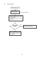
EEPROM Initialization
There are two methods for initializing the EEPROM, as shown below.
(1) Initializing EEPROM When Turning On the Power
1) TW/TX Series: Press down the [BREAK] and [PRINT] keys, and switch on the power.
TXB Series: Press the [BREAK] key, switch on the power, then while "CHE 5" is displayed, press down
the [BREAK] and [PRINT] keys at the same time.
2) "EE INIT" is displayed.
3) Press the [MENU/Enter] key to display "PART".
Press either the [FUNC] or [UNIT] key to display "ALL".
4) - In the "PART" display, keep pressing the [MENU/Enter] key until changing to “CHE 3” display: Initializes
part of EEPROM data.
Write to EEPROM the temperature correction coefficient, linearity correction coefficient, and model
setting information (weight capacity, minimum display) that is backed up on Flash memory.
- In the "ALL" display, keep pressing the [MENU/Enter] key until changing to “CHE 3” display: Initializes
all EEPROM data, and write to EEPROM.
5) After initialization, move to the service mode.
(2) Initializing EEPROM from Service Menu
1) In the service menu, select [NVRAM] -> [INIT (All Initialize)].
2) The execution confirmation display [OK?] appears.
3) Press the [MENU/Enter] key to execute.
4) The initializing display appears.
5) When initialization is completed, return to the service menu AD value display.
5.2.
Model Selection
Select the Shimadzu standard model name. The operation procedure is as shown below.
1) In the service menu, press either the [FUNC] or [UNIT] key, and then select [Model Selection] (TYPE).
2) Press the [MENU/Enter] key.
[Menu display example for model selection]
[Caution]
If TYPE does not appear on the
menu display, the setting
information lock must be released.
* See "5.3.1 Releasing the Setting
Information Lock."
(4) Press either the [FUNC] or [UNIT] key to read out the model name stored in EEPROM, and display it on
the LCD.
[Display example for model name TX323L]
(5) Press the [MENU/Enter] key to determine the model.
- 35 -
- Model name display is a maximum of seven characters. (Due to limitation to the panel display, numbers
are displayed on the left and alphabetical characters on the right, separated by a "." dot.)
- If the OEM setting is set to ON, and the specified model name has not been input, a corresponding
Shimadzu standard model name will be displayed.
[Model Settings]
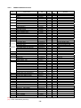
For TX/TXC,TXB of Ver 1.00,XX,XX
Display
Model Name
323.TXC
623.TXC
223.TX
323.TX
2202.TX
3202.TX
222.TXB
422.TXB
622.TXB
621.TXB
2201.TXB
4201.TXB
6201.TXB
6200.TXB
TXC323L
TXC623L
TX223L
TX323L
TX2202L
TX3202L
TXB222L
TXB422L
TXB622L
TXB621L
TXB2201L
TXB4201L
TXB6201L
TXB6200L
Specifications
(weight capacity, minimum display)
320 ct/0.001 ct (64 g/0.0002 g)
620 ct/0.001 ct (124g /0.0002 g)
220 g/0.001 g
320 g/0.001 g
2,200 g/0.01 g
3,200 g/0.01 g
220 g/0.01 g
420 g/0.01 g
620 g/0.01 g
620 g/0.1 g
2,200 g/0.1 g
4,200 g/0.1 g
6,200 g/0.1 g
6,200 g/1 g
For TW,TWC/TX,TXC ( except for TXB ) of Ver2.00,XX,XX and over
Display
Model Name
323.TXC
623.TXC
223.TX
323.TX
423.TX
2202.TX
3202.TX
4202.TX
323.TWC
623.TWC
223.TW
323.TW
423.TW
2202.TW
3202.TW
4202.TW
TXC323L
TXC623L
TX223L
TX323L
TX423L
TX2202L
TX3202L
TX4202L
TWC323L
TWC623L
TW223L
TW323L
TW423L
TW2202L
TW3202L
TW4202L
- 36 -
Specifications
(weight capacity, minimum display)
320ct/0.001ct (64g/0.0002g)
620ct/0.001ct (124g/0.0002g)
220g/0.001g
320g/0.001g
420g/0.001g
2200g/0.01g
3200g/0.01g
4200g/0.01g
320ct/0.001ct (64g/0.0002g)
620ct/0.001ct (124g/0.0002g)
220g/0.001g
320g/0.001g
420g/0.001g
2200g/0.01g
3200g/0.01g
4200g/0.01g
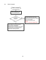
5.3.
Setting Information Lock
There will be cases where the setting information lock must be released due to calibration error, etc., to reselect
the model and perform readjustment.
In such cases, follow the procedure below to release and set the setting information lock.
5.3.1.
Releasing the Setting Information Lock
(1) In the service menu, select “NVRAM” -> “EDIT” (Data edit).
* See "6.2 Data Edit (EDIT) Operations."
(2) Input the address "28E", and edit the lowest byte (right side: Address No.28F) from "01" to "00".
(3) In the service menu, check that “TYPE” is displayed next to “LINEAR”.
5.3.2.
Setting the Setting Information Lock
(1) In the service menu, select [LOCK].
(2) The “OK?” confirmation is displayed. Press the [MENU/Enter] key to lock the setting information.
[Caution] If the setting information is not locked, the calibration error check will not occur.
Therefore, even if an unsuitable weight is used during calibration, or if an unsuitable calibration
operation is performed, the sensitivity calibration coefficient is calculated without any conditions,
resulting in problems in the measurement data display.
- 37 -
5.4.
Inputting Reference Weight Values for Linearity Adjustment
Before executing linearity adjustment, input the reference weight values to be used.
(1) Enter service mode and select [LINEAR] -> [L.W.SET].
(2) Determine the reference weight required for linearity adjustment, depending on the model setting.
(The mass of the weight and the number of measurements required)
(3) The reference weights required are displayed.
(4) Input the reference weight mass (including the certified value). See the table below, "Linearity Adjustment
Reference Weights."
(5) Confirm the reference weight value input. (5 points, excluding 0)
(6) Repeat steps (4) and (5) up to the number of reference weights required.
(7) When input for all weights is completed, return to the menu item display for linearity adjustment weight
value input.
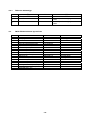
[Linearity Adjustment Reference Weights]
It may different Weight value after EEPROM initializing or model setting.
Model name
TXC323L
TWC323L
TXC623L
TWC623L
TX223L
TW223L
TX323L
TW323L
TX423L
TW423L
TX2202L
TW2202L
TX3202L
TW3202L
TX4202L
TW4202L
TXB222L
TXB422L
TXB622L
TXB621L
TXB2201L
TXB4201L
TXB6201L
TXB6200L
Number of
Measurements
Reference Weight Value
CAL Value
6
0
15
30
45
60
65
50
6
0
30
60
90
120
130
100
6
0
50
100
150
200
250
200
6
0
100
150
200
300
350
200
6
0
100
200
300
400
450
400
6
0
500 1000 1500 2000 2500
2000
6
0 1000 1500 2000 3000 3500
2000
6
0 1000 2000 3000 4000 4500
4000
6
6
6
6
6
6
6
6
0
50 100 150
0 100 200 300
0 150 300 450
0 150 300 450
0 500 1000 1500
0 1000 2000 3000
0 1500 3000 4500
0 1500 3000 4500
200
400
500
500
2000
4000
5000
5000
- 38 -
200
400
600
600
2000
4000
6000
6000
250
450
650
650
2500
4500
6500
6500
5.5.
Linearity Adjustment
To satisfy linearity specifications, calculate the coefficient for correcting hardware linearity errors.
The operation procedure is as shown below.
(1) Press the [MENU/Enter] key, and select “LINEAR” -> “L.ADJUST”.
(2) “START” displaying and press the [MENU/Enter] key.
(3) Following the display for the previously input linearity adjustment weight value, place a weight on the pan,
and after the stability mark appeared, press the [MENU/Enter] key to confirm the measurement, then
proceed to the next measurement.
Example of weight value display:
Flashing
(4) When all adjustment data measurement is completed, the correction coefficient is calculated and saved in
EEPROM automatically.
5.6.
Calibration of internal weight ( PCAL ) (Only TW series)
Execute internal weight calibration in the same way as user mode.
Reference weight for PCAL is shown in the bellow table.
Confirm nothing on the pan before executing PCAL.
[ Reference weight ]
Model name
TWC323L
TWC623L
TW223L
TW323L
TW423L
TW2202L
TW3202L
TW4202L
CAL Value
50g
100g
200g
300g
400g
2000g
3000g
4000g
1) Keep pushing [ CAL ] key until display changes.
2) “P.CAL” is displayed pushing [ UNIT ] key or [ FUNC ] key.
Then [MENU/ENTER] key is pushed.
3) If an error occurs, display the error code.
For error content, see section 6.6.2.
4) If no occurs, update the sensitivity correction coefficient and save to EEPROM.
In addition, back up the sensitivity correction coefficient to Flash memory.
5) After completion, return to the AD value display.
- 39 -
5.7.
Sensitivity Calibration by External weight
Execute sensitivity calibration in the same way as user mode.
If sensitivity calibration is executed in service mode while setting information is locked, any errors that occur
result in display of detailed error codes.
Execute sensitivity calibration using the same operation as user mode.
Procedures
(1) Press the [CAL] key.
(2) Execute sensitivity calibration.
(3) If an error occurs, display the error code.
For error content, see section 6.6.2.
(4) If no occurs, update the sensitivity correction coefficient and save to EEPROM.
In addition, back up the sensitivity correction coefficient to Flash memory.
(5) After completion, return to the AD value display.
While detailed error codes are not displayed in user mode, they are displayed in service mode, as shown in
the table below. To return from the error display, press the [Break] key.
Code
Error Name
Description
C-ERR1 Instability error
Measurement value at zero point or weight measurement is unstable.
Stabilization mark failed to light up even after 15 seconds had elapsed since
weight was placed or removed.
C-ERR2 Zero point error
Drift from zero point since last sensitivity calibration is large. Object
exceeding 20% of weight capacity is placed on the pan, or a change in the
zero point equivalent to excess of 20% of weight capacity occurred.
C-ERR4 Span error
Difference between the set reference weight value and measured weight
span value exceeds 2% of the weight mass.
i. Operation and execution of sensitivity calibration, and the operating procedure for the sensitivity
calibration menu is the same as in the user mode, and does not appear as a service mode menu item.
ii. Prepare the reference weights listed in the table below for CAL values.
[Reference Weight Values]
Model Name
TXC323L
TWC323L
TXC623L
TWC623L
TX223L
TW223L
TX323L
TW323L
TX423L
TW423L
TX2202L
TW2202L
TX3202L
TW3202L
TX4202L
TW4202L
CAL Value
50
100
200
200
400
2000
2000
4000
- 40 -
[Reference Weight Values]
Model Name
TXB222L
TXB422L
TXB622L
TXB621L
TXB2201L
TXB4201L
TXB6201L
TXB6200L
5.8.
CAL Value
200
400
500
500
2000
4000
5000
5000
Sensitivity Calibration by internal weight (Only TW series)
Execute sensitivity calibration in the same way as user mode.
If sensitivity calibration is executed in service mode while setting information is locked, any errors that occur
result in display of detailed error codes.
Execute sensitivity calibration using the same operation as user mode.
Procedures
(1) Press the [CAL] key.
(2) Execute sensitivity calibration.
(3) If an error occurs, display the error code.
For error content, see section 6.6.2.
(4) If no occurs, update the sensitivity correction coefficient and save to EEPROM.
In addition, back up the sensitivity correction coefficient to Flash memory.
(5) After completion, return to the AD value display.
While detailed error codes are not displayed in user mode, they are displayed in service mode, as shown in
the table below. To return from the error display, press the [Break] key.
Code
Error Name
Description
C-ERR1 Instability error
Measurement value at zero point or weight measurement is unstable.
Stabilization mark failed to light up even after 15 seconds had elapsed since
weight was placed or removed.
C-ERR2 Zero point error
Drift from zero point since last sensitivity calibration is large. Object
exceeding 20% of weight capacity is placed on the pan, or a change in the
zero point equivalent to excess of 20% of weight capacity occurred.
C-ERR4 Span error
Difference between the set reference weight value and measured weight
span value exceeds 2% of the weight mass.
i. Operation and execution of sensitivity calibration, and the operating procedure for the sensitivity
calibration menu is the same as in the user mode, and does not appear as a service mode menu item.
ii. Prepare the reference weights listed in the table below for CAL values.
- 41 -
5.9.
Weight loader check ( Only TW series )
Execute confirmation of weight loader function.
Procedure
1) Push the [MENU] key and select ”LD.W” .
2) Select ”HOME” or ”LD.UNLD”.
“HOME” = Return to initial position
“LD.ULD” = Internal weight is loaded or unloaded to UNIT ASSY.
- 42 -
6. EEPROM
Flash Memory in CPU
[INIT]
ROM program area
OUTPUT
EEPROM data
Back Up area
RAM
(EEPROM data area)
[EDIT] by ENTER key
When the turn on the power,
[RESTR]
EEPROM
[PRINT]
copying automatically.
[BKUP]
Temperature coefficient data
Creep coefficient data
Error check
Error log
Password of user mode
6.1.
Address No.
004∼05A
14A∼158
28F
288∼28D
3BE∼3BF
Ref.
TXB only
ON:01 OFF:00
For 5 logs
9999:”3BE.0F27”
PRINT Operations
(1) In the service menu, select “NVRAM” -> “PRINT”(Print).
(2) The model name, S/N, software version No., and the address inside EEPROM are displayed as the
header, and then data is printed.
[Print example]
TYPE : TX223L
S/N : 0000000000
V NO : 1.00,00,15
0000 : 07AB
0002 : ACAB
0004 : 0041
0006 : 0E47
x
x
(3) When printing of all data is completed, return to the service menu AD value display.
- 43 -
6.2.
Data Edit (EDIT) Operations
(1) In the service menu, select “NVRAM” -> “EDIT”(Data edit).
(2) Data with address in EEPROM are displayed as shown below.
The flashing value can be changed.
Flashing
(3) Input the address of the data to be edited. The address data is displayed (in the right four digits).
(4) Press the [MENU/Enter] key to confirm the address, and editing of that address data is enabled.
Flashing
(5) Edit the data.
(6) Press the [MENU/Enter] key to confirm the data, and the changed address data is saved.
(7) To continue editing, repeat the procedure from step (1).
When completed, press the [BREAK] key. Return to the service menu AD value display.
6.3.
Backup (BKUP) Operations
(1) In the service menu, select “NVRAM” -> “BKUP (Backup)”.
(2) The execution confirmation display “OK?” appears.
(3) Press the [MENU/Enter] key. Data in EEPROM is backed up and saved to the microcomputer Flash
memory.
(4) The backup progress indicator appears.
(5) When backup is completed, return to the service menu AD value display.
6.4.
Download (RESTR) Operations
(1) In the service menu, select “NVRAM” -> “RESTR”(Download).
(2) The execution confirmation display “OK?” appears.
(3) Press the [MENU/Enter] key. Data backed up in the microcomputer FLASH memory is transferred to
EEPROM.
(4) The download progress indicator appears.
(5) When download is completed, return to the service menu AD value display.
- 44 -
6.5.
All Initialization (INIT) Operations
(1) In the service menu, select “NVRAM” -> “INIT”(All Initialize).
(2) The execution confirmation display “OK?” appears.
(3) Press the [MENU/Enter] key to execute.
(4) The initialization progress indicator appears.
(5) When initialization is completed, return to the service menu AD value display.
6.6.
EEPROM data editing software
Confirm communication settings of the balance. (Especially, Handshaking)
1) Run “T-tool” software.
2) Choose com port number.
3) Choose “8. NVRAM editor”
- 45 -
4) Editing NVRAM menu
Downloading EEPROM data
It appeared file name after data
from the balance to PC
saving to PC or downloading
It assign S/N and model
data from PC.
name to the file name
automatically.
Uploading data to the
balance.
When
choose
[Y],
uploading all data.
When
choose
[N],
uploading edit data only
1.
2.
It appeare unit
information from the
EEPROM data.
Downloading
from PC.
data
It back previous downloading
data when missing input data
5) Back-up EEPROM data by “BKUP” in the service menu.
- 46 -
Input
address
number.
Get data from left
side data table.
Reflect edit data to left
side data table.
It changes red color after
reflecting.
It is not loading to
balance at this condition.
7. Updating the Program
The TW/TX/TXB Series has a Flash memory microcomputer. You can use a special tool to easily update the
program at customer site.
7.1.
Programming Tools
Programming is performed using the following tools.
P/N
774-49154
774-41751
Name
Flash Programmer SW-K0LX2
Cable, Program Writer
7.2.
Programming
7.2.1.
Downloading the Program to the Tool
Procedure
1) Set the Flash programmer SW-K0LX2 power switch to [U].
Output switch: 5
Status LED
2)
Power switch: U
Remove the USB connector cap from the Flash programmer SW-K0LX2, and connect the Flash
programmer SW-K0LX2 to a USB connector on the PC.
- 47 -
3)
4)
In the Windows Start menu, select [StickWriter] -> [StickWriter] and start up the application.
The window shown below is displayed.
(1)
5)
Click the [Download] button (1).
- 48 -
6)
7)
The window below is displayed. Select the program file (*.HEX) to download.
Selecting the folder containing the program file displays that program file (*.HEX).
Click the file name, and click [Open] to start downloading the program file to Flash programmer SW-K0LX2.
When the download is completed, "HEX File Information Upload Completion" is displayed in the status
display area (2).
(2)
- 49 -
8)
The downloaded program file information is displayed in the "HEX File" area (3). Check the file name and file
time stamp.
(3)
9) Close the application.
10) Remove Flash programmer SW-K0LX2 from the PC.
- 50 -
7.2.2.
Preparing the Tool
Procedure
1) Check that the Flash programmer SW-K0LX2 (774-49154) switches are set as shown in the figure below.
(1) Output: 5
(2) Power: T
5
T
2) Connect the program writer cable (774-41751) to the accessory FP4 adaptor for the Flash programmer
SW-K0LX2 (774-49154).
FP4 adaptor →
Check!
SW-1
- 51 -
1:ON
2:ON
Connect the FP4 adaptor and program writer cable (774-41751).
- Be careful not to injure your fingers or hands with the unconnected pins.
- Since a wiring disconnection will prevent programming from being completed,
be careful when handling.
3) Connect the Flash programmer SW-K0LX2 (774-49154) to the cable prepared in step 1).
To connector for display
board program writer
7.2.3.
Programming
Procedure
1) Check that the TW/TX/TXB power is switched off.
2) Insert the 6-prong connector of the tool prepared in section 7.2.2 into the connector for the display board
program writer.
Program writer connector:
TW/TX: J1 connector
TXB: J3 connector
- 52 -
3) Switch on the power to TW/TX/TXB.
TW/TX: Attach the AC adaptor to the power jack.
TXB: Attach the AC adaptor to the power jack, and keep pressing the [BREAK] key.
Status LED
4) Programming starts and the Status LED [P] flashes. Blue LED flashing during uploading.(one LED only)
Note: Shutting off the power while the Status LED [P] is flashing could cause
programs in display board CPU and programs in the Flash programmer
SW-K0LX2 to disappear. Be particularly careful with TXB.
5) Programming is completed in about 30 - 40 seconds, and the Status LED [P] changes from flashing to
lighted. At the same time, Status LED [S] lights. (Two LED lighting after up-load completing.)
6) Switch off the power to TX/TXB.
7) Disconnect the tool.
8) Switch on power to the balance, and check that the Version number and balance operates.
9) Back-up EEPROM data to the flash memory.(Choose “BKUP” of the service menu)
Special Note: If programming fails, Status LED [F] lights up in red color.
In this case,
x Shut off power to the TX/TXB, disconnect the connection to the tool and the display
board connector, and restart programming from step 1).
x If programming fails even after repeating the above steps, there may be a break in the
program writer cable (774-41751). Replace the cable.
When replacing the program writer cable (774-41751), follow steps 1) to 3) in section
10.2.2 in reverse order to remove the cable.
Don’t forget EEPROM data back up [BKUP] after reloading ROM program (ROM version up).
- 53 -
8. Performance Inspection
Before starting the performance inspection, turn on the power and leave the balance in the mass display state
(backlight turned on) for at least an hour.
Also be sure that the location is not subject to wind, vibrations, or sudden temperature changes.
8.1.
Reproducibility
1) Place the weight specified in Table 1 on the center of the pan, and then remove it. Repeat this five times to find
the amount of variation at the zero point and the weighing capacity, Rx and Ry.
Rx = X max − X min
R y = Ymax − Ymin
: X 1 , X 2 ・・・X 5
: Y1 , Y2 ・・・Y5
("max" shows the maximum value, and "min" shows the minimum value.)
8.2.
1)
2)
3)
4)
Cornerload Error
Prepare the weight specified in Table 1.
First place the weight on the pan center (see Fig. 24 in 4.1.3 Adjusting the Cornerload Error). Then move the
weight in the order of 2 → 3 → 4 → 5 → 1, while recording the display at each position.
If the differences (cornerload error) between the display values at the positions 2, 3, 4, and 5, and the display
value at the center position (1) are all within the criteria, conditions are normal.
Example: (Error at position 3) = (Display value at position 3) - (Average of two display values at position 1)
If the errors are minor, follow "4.1.3 Adjusting the Cornerload Error".
* This adjustment is only effective for minor errors (within ±30 counts).
If the error is larger, replace the unit Assy (1).
8.3.
Linearity
1) Use a weight to execute "E CAL" once.
2) Place weights in the order shown in Table 1, and record the display value when it stabilizes.
3) Calculate the error at each load.
(Error) = (Display value at each load) - (Average of zero point display values) - (Weight certified value)
4) If the errors are minor, follow "5.5 Linearity Adjustment".
* This adjustment is only effective for minor errors (within ±10 counts).
If the error is larger, replace the unit Assy (1).
8.4.
Tilt Error
10) Press the "->0/T<-" key to change to the "0g" display. (A)
11) Insert a plate with thickness of 1 mm under the two right level adjustment feet and, when the display is
stable, record the display value. (B)
(Error) = (B) - (A)
12) If the error is large, follow "4.1.2 Adjusting the Tilt Error".
- 54 -
Table 1 TW/TX Series Inspection Criteria
Model
Weighing Capacity
Minimum Display
Reproducibility
(Rx, Ry)
Weight
Cornerload
Error
Weight
Linearity
Tilt Error
TWC323L
TXC323L
TWC623L
TXC623L
TW223L
TX223L
TW323L
TX323L
TW423L
TX423L
TW2202L
TX2202L
TW3202L
TX3202L
TW4202L
TX4202L
320ct
620ct
220g
320g
420g
2,200g
3,200g
4,200g
0.001ct
0.001ct
0.001g
0.001g
0.001g
0.01g
0.01g
0.01g
0.006ct
0.006ct
0.006g
0.006g
0.006g
0.06g
0.06g
0.06g
300ct
(60g)
500ct
(100g)
200g
300g
400g
2,000g
3,000g
4,000g
±0.002ct
±0.002ct
±0.002g
±0.002g
±0.004g
±0.02g
±0.02g
±0.04g
150ct
(30g)
250ct
(50g)
100g
150g
200g
1,000g
1,500g
2,000g
±0.004ct
±0.004ct
±0.004g
±0.004g
±0.004g
±0.04g
±0.04g
±0.04g
±0.05ct
±0.05ct
±0.03g
±0.03g
±0.03g
±0.3g
±0.3g
±0.3g
Table 2 TXB Series Inspection Criteria
Model
Weighing Capacity
Minimum Display
Reproducibility
(Rx, Ry)
TXB222L
TXB422L
TXB622L
TXB621L
220 g
420 g
620 g
620 g
0.01 g
0.01 g
0.01 g
0.1 g
0.06 g
0.06 g
0.06 g
0.6 g
200 g
400 g
600 g
600 g
±0.02 g
±0.02 g
±0.02 g
±0.2 g
100 g
200 g
300 g
300 g
±0.04 g
±0.04 g
±0.04 g
±0.4 g
±0.3 g
±0.3 g
±0.3 g
±3 g
TXB2201L
TXB4201L
TXB6201L
TXB6200L
2,200 g
4,200 g
6,200 g
6,200 g
0.1 g
0.1 g
0.1 g
1g
0.6 g
0.6 g
0.6 g
6g
Weight
2,000 g
4,000 g
6,000 g
6,000 g
±0.2 g
±0.2 g
±0.2 g
±2 g
Weight
1,000 g
2,000 g
3,000 g
3,000 g
±0.4 g
±0.4 g
±0.4 g
±4 g
±3 g
±3 g
±3 g
±30 g
Weight
Cornerload Error
Weight
Linearity
Tilt Error
Model
Weighing Capacity
Minimum Display
Reproducibility
(Rx, Ry)
Cornerload Error
Linearity
Tilt Error
- 55 -
9. Problems and Solutions
9.1.
General Problem Solutions
Problem
Cause
Solution
Nothing appears on the
display
1) Power voltage not compatible.
Check the power supply, and connect
correctly.
Replace the AC adaptor.
Numerals or symbols
not displayed properly
Key operation does not
work
"0L" or "-0L" is displayed
Large zero or span drift
Span is incorrect
2) Problem with supply voltage or
AC adaptor
3) Power board Assy (B4) fault
4) Main board Assy (B2) fault
1) Main board Assy (B2) fault
1) Main board Assy (B2) fault
2) Fixing fault in case Assy (3)
1) Contact with stopper plate (U14)
and stabilizer pin
2) Pt-Ni band (U17) fault
3) Contact with force coil Assy (L1)
and magnet Assy (U9)
4) Force coil Assy (L1) fault
5) Damage to OPF (U1)
6) Detector Assy (U11) fault
7) Analog board Assy (B3) fault
1) Not enough time allowed for
warmup
2) Unit under direct sunlight, or
subject to breeze from air
conditioner
1) Not horizontally adjusted
2) Balance has been relocated
Large cornerload error
(30 d or larger)
Poor measurement
reproducibility
Large fluctuation in
display values
Difficulty in getting
stability mark to light up
3) Damage to OPF (U1)
1) Damage to OPF (U1)
2) Load cell breakdown
1) Affected by breezes or vibration
2) Cable between detector Assy
(U11) and analog board Assy
(B3) contacts the base
3) Contact with stopper plate (U14)
and stabilizer pin
4) Contact with force coil Assy (L1)
and magnet Assy (U9)
5) Dust adheres to inside of force
coil Assy (L1) or magnet Assy
(U9)
6) Temperature sensor fault
7) Damage to OPF (U1)
8) Analog board Assy (B3) fault
9) Detector Assy (U11) fault
TW/TX
9
9
9
Replace the power board Assy (B4).
Replace the main board Assy (B2).
Replace the main board Assy (B2).
9
9
9
9
9
9
Replace the main board Assy (B2).
Refix the case Assy (3) in place.
Realign the stopper plate (U14).
9
9
9
9
9
9
Check the Pt-Ni band (U17), and
connect correctly.
Reset or replace the force coil Assy (L1).
Replace the force coil Assy (L1).
Replace the unit Assy (1).
Replace the detector Assy (U11).
Replace the analog board Assy (B3).
Perform unit warmup.
Change the balance installation site.
Use the level adjustment feet (B6) to
adjust the level.
Calibrate the span (sensitivity) at the
current installation site.
Replace the unit Assy (1).
Replace the unit Assy (1), and readjust.
Replace the load cell Assy, and readjust.
Relocate the balance. Change to
high-stability settings.
Rearrange the cable.
Realign the stopper plate (U14).
Reset or replace the force coil Assy (L1).
Remove dust.
Re-solder the temperature sensor to the
detector Assy (U11).
Replace the unit Assy (1).
Replace the analog board Assy (B3).
Replace the detector Assy (U11).
9
9
9
9
9
9
9
9
9
9
9
9
9
9
9
9
9
9
9
9
9
9
9
9
9
9
9
9
Unstable display
1)Touching bottom of Pan supporter
and Notch of Pan ring
TXB
Four Notches of Pan Ring are inserted in
exactly. (Refer to “Installation” in the
instruction manual.)
- 56 -
9
9
Problem
Large linearity
error
"ERR H" is
displayed
With power
switched on
display stops at
"CHE 0"
9.2.
9.2.1.
Cause
Solution
1) Linearity adjustment fault
Readjust linearity.
If over 10 d, replace the unit.
Replace the unit Assy (1).
Replace the load cell Assy.
Restart the power.
2) Damage to OPF (U1)
3) Load cell breakdown
- StickWriter used to write a
program, resulting in data
mismatch
between
microcomputer and EEPROM.
(Restart the power, and if no error
display appears, the situation is
normal.)
- Breakdown
of
temperature
sensor used to measure and
correct
UniBloc
sensor
temperature characteristics. .
- Abnormal data for various
correction coefficients for mass
display, balance information, and
menu setting conditions, etc.
- Weight loader Assy(27) fault
(TW only)
(snapping, sensor fault, short of
motor coil)
EEPROM not set correctly.
TW/TX
TXB
9
9
9
9
9
Check the sensor solder.
Check the TAD value.
9
9
Download the data again.
9
Check connect and sordering of wires.
Replace the weight loader Assy(27)
Replace the main board Assy(B2(
9
9
Reset the EEPROM.
9
9
Error Display
User Mode Errors
Display
ERR H
Error Name
Description
Hardware error
Breakdown of temperature sensor used to measure and correct UniBloc
sensor temperature characteristics.
Abnormal data for various correction coefficients for mass display, balance
information, and menu setting conditions, etc.
Weight loader Assy(27) fault
ERR C
Sensitivity calibration
error
ERR N
Numerical input error
ERR W
COM ERR
OL
- OL
Battery
Mark
WAIT
Operations error
External input error
ABORT
Power voltage drop
Calibration weight not placed on the pan. Something else is placed on the
pan.
The calibration weight is wrong.
Too small a number has been input for reference number settings.
Too small a mass has been input for reference percentage settings.
The password entered is not recognized, when using a function that requires
password entry.
Specific gravity, loading, formulation, or other mode operation error.
Unidentifiable command code received.
Weight capacity exceeded.
Measurement pan was removed.
Lights up when voltage supplied to the microcomputer is at or below the
specified voltage.
Wait for operation
approval
Abort
- 57 -
9.2.2.
Service Mode Errors
When entering service mode, detailed error codes are displayed for the errors generated in user mode, as
shown in the table below. In this state, press the -> key to display a history of the most recent errors, up to a
maximum of five errors.
When more than five errors are displayed, press the -> key to return to the display of the most recent errors.
If entering service mode when no errors have been generated, “NO ERR” is displayed, as shown in the
table below.
User Mode Error Service Mode Error Name
Name
No Errors
System Error
Display
No errors occurred during user mode.
Temperature Sensor Error (Err1)
Abnormal temperature data due to
temperature sensor malfunction.
EEPROM Data Error (Err5)
Abnormal mass calculation due to
EEPROM data abnormality.
Stabilization Error (CAL E1)
Measurement value at zero point or
weight measurement is unstable.
Zero Point Error (CAL E2)
Drift from zero point since last sensitivity
calibration is large. Object exceeding
20% of weight capacity is placed on the
pan, or a change in the zero point
equivalent to excess of 20% of weight
capacity occurred.
Difference between the set reference
weight value and measured weight
span value exceeds 2% of the
reference weight mass.
(Hardware Error)
Sensitivity
Calibration Error
Span Error (CAL E4)
9.2.3.
Description
Self check when power is turned on
Ver 1.XX.XX.XX
CHE 5
CHE 4
CHE 3
CHE 2
CHE 1
CHE 0
Display
Ver 2.XX.XX.XX ~
Ver No.
CHE 3
CHE 2
CHE 1
CHE 0
Content of self check
Initializing of AD converter
Check of EEPROM data initializing(in CPU area) operation
Copy of EEPROM data to CPU
Initialize(return to home) of internal CAL system(TW Ver 2.XX~)
Temperature sensor(TAD) check
Check of start display (g/OFF/8888)
Preparation of measurement
(Weighing-mode, Application function, Communication setting, etc.)
- 58 -
10. Troubleshooting
10.1.
Display Won't Appear
Display won't appear.
TW/TX?TXB?
TXB
Press the [BREAK] OK
key.
TW/TX
NG
No
[CHE 5,4,3,2,1]
↓
[OFF] display
(Normal)
Dry batter
drive?
Yes
If AC adaptor is connected, recheck the AC jack,
and restart the power.
Or replace the AC adaptor, and restart the power.
10.2.
If using dry battery drive in TXB, check the battery
life, the +/- direction, and insertion state, and
restart the power.
Display Not Showing Correctly
Display not showing correctly.
Restart the power and light
up all segments.
Are there any
segments not
lighted up?
No
Yes
Replace the main board Assy,
restart the power, and check
again.
- 59 -
Check again.
10.3.
Key Operation Does Not Work
Key operation does not work.
Remove the upper case, and
switch on the power.
Press a key.
Does it operate
normally?
No
Yes
Reset the upper case, adjust the key
action, and switch on the power.
- 60 -
- Replace the main board Assy,
restart the power, and check
the key action.
- Follow [10.6 When Power is
Switched On, Display Stops at
"CHE 5" or “Software Version”。
10.4.
Poor Reproducibility
Reproducibility is poor.
Remove the upper case
and unit cover.
* Unit cover is for TX only
- Check the cable between the detector
and analog boards.
- Check the cable around the stopper
plate and coil.
Is the connection
cable contacting
the base?
No
Replace the main board Assy, restart
the power, and check again.
Yes
Reset the upper case and unit
cover so that the cable does not
contact the base.
- 61 -
10.5.
"ERR H" Is Displayed
"ERR H" is displayed.
Switch off the power, and
then restart the power.
Is "ERR H"
displayed?
Yes
- Check the temperature sensor solder.
- Replace the main board Assy, restart the
power, and check again.
- Replace the temperature sensor.
- For TW
No
Refer to “10.8 Trouble of Weight Loader”
After using StickWriter to write a program, a
data mismatch occurred between the
microcomputer and EEPROM.
Restart the power to match the data. There is
no problem if the error display does not
appear after restarting the power.
- 62 -
10.6.
When Power is Switched On, Display Stops at "CHE 5" or “Software Version”
CAUSE:Failur of AD convertor IC initialization.
Install new software, if software version is under 2.XXXXXX.
Display stops at
"CHE 5" or "S/W Ver"
Yes
No
Display stops at
"CHE 5"?
Display stops at
Display stops at
"CHE 5"
" S/W Ver "
Re-install the program,
Check connection cable of MAIN
BOARD and ANALOG BOARD
Refer to 7.2.3 Programming.
Use program that software version
is over 3.XXXXXX.
CORRECT?
Display stops at
" S/W Ver "?
No
OK
Yes
Yes
1)Replace the cable
2)Replace the MAIN BOARD
3)Replace the ANALOG BOARD
- 63 -
No
Re-connect the cable
10.7.
When Power is Switched On, Display Stops at "CHE 0"
Display stops at "CHE 0".
Check the EEPROM on the main
board, reset it, and then restart
the power.
When power is
switched on does it
advance to OFF
display?
No
Yes
Check whether the balance is
operating normally.
- 64 -
Replace the main board Assy,
restart the power, and check
again.
10.8.
Trouble of Weight Loader
Trouble of Weight Loader
Connect other Weight Loader
assy to MAIN BOARD ASSY
GOOD?
Yes
No
Replace Weight Loader
assy
Replace MAIN BOARD
GOOD?
No
Replace the connection cable of
MAIN BOARD and POWER BOARD
- 65 -
11. Components List
11.1.
11.1.1.
TW/TWC,TX/TXC series
TW/TWC,TX/TXC exploded view
C4
TXC series(old TXC)
C5
C3
6
C6
4
7
C7
C10
C10
C1
C8
8
P4
1
P3
B4
B23
B3
B7
B2
B9
B6
- 66 -
TX series (old small pan)
C4
C5
C3
6
C6
4
C7
C10
C10
C1
C8
8
P4
1
P3
B4
B23
B3
B7
B2
B9
B6
- 67 -
TX series (old large pan)
6
8
C1
5
P4
P3
1
B4
B23
B3
B7
B2
B9
B6
- 68 -
TWC/TXC series (TWC/TXC common)
C4
C3
6
4
C6
7
C10
C13
C10
C8
C1
1
8
P4
B4
B23
P3
B3
B7
B2
B9
27
B6
- 69 -
TW/TX series(TW/TX common, small)
C4
C5
C3
C6
6
4
C10
C13
C10
C1
C8
8
1
P4
B4
P3
B23
B3
B7
B2
B9
27
B6
- 70 -
TX series(Large)
6
8
C1
5
P4
P3
1
B4
B23
B3
B7
B2
B9
27
B6
- 71 -
TX series (unit assv(carat/small pan)(1) )
U17
U11
U19
U9
U20
TX series (unit assv (large pan)(1) )
U17
U11
U19
U9
U20
- 72 -
TW series(unit assy(carat/small pan)(1))
U17
U11
U19
U9
U20
- 73 -
TW/TWC/TX/TXC Series Maintenance Parts
No.
1
4
5
6
7
8
27
B2
B3
B4
Product name
P/N
Unit assy, TX (carat)
321-64620-01
Unit assy, TX (small)
321-64620-02
Unit assy, TX (large)
321-64620-03
Unit assy, TXC623L
321-64620-04
Unit assy, TX423L
321-64620-05
Unit assy, TW (carat)
321-64620-21
Unit assy, TW (small)
321-64620-22
Unit assy, TW (large)
321-64620-23
Pan support assy, carat
321-64518
Pan support , carat
321-64588
Pan support, small pan
321-64589
Cap, pan support
321-64591
Pan (φ80)
321-41225
Pan (φ110)
321-41418-10
Pan, large
321-64587
Wind shield ring
321-41205-11
TXC
323
323/
(*4)
623
TX
Small
pan
Large
pan
TWC
323/
623
TW
9
*1,*9 TXC323L only
(9)
*1,*9 TX223L/323L only
9
9
*1
9
*1,*10 TXC common
*1,
*10 TX(small)common
*1
9
9
9
9
9
9
9
9
9
9
9
9
9
9
9
9
Cover plate, carat/small pan
321-64593
Cover plate, large pan
321-64594
Weight loader assy,TW
321-70965
Main board assy
321-64553-01
(9)
Main board assy
321-64553-03
9
Main board assy (TXC623L)
321-64553-14
Main board assy
321-64553-05
9
SW,TACT PTM114NN
064-48205-21
LCD,EDC6671 TRANSFL
321-63860-02
BACKLIGHT,EDM6671
321-63861
BACKLIGHT,EDM8070
321-71121
Analog board assy (TXC323L)
321-64556-13
9
9
9
9
(9)
Analog board assy (TXC623L)
321-64556-14
Analog board assy (small)
321-64556-11
9
9
9
9
9
9
9
9
9
(9)
(9)
9
9
9
9
9
9
9
9
9
9
9
9
9
9
9
9
9
9
9
9
9
9
9
9
9
9
9
9
9
9
(9)
9
9
*Compatible
*Compatible
*1
9
9
*1
*1
*5TX only
Analog board assy (large)
321-64556-12
Power board assy
321-64550
(9)
(9)
(9)
(9)
9
9
9
(9)
9
9
9
9
(9)
9
9
9
9
(9)
9
9
9
9
9
9
*6TW/TX common
*7 PCBA between
TX onlyTW/TX common
Power board assy
321-64550-01
321-64540
B7
Level assy
321-70691-01
Cable, ILS 10S-10S-300
321-64566-03
Cable, ILS 11S-11S-440
321-64566-05
9
9
9
(9)
9
Cable, ILS 10S-11S-440
321-64566-06
(9)
(9)
(9)
(9)
(9)
(9)
022-66298-01
9
9
9
9
9
9
321-64576-11
9
9
9
9
9
9
9
9
9
9
9
9
9
9
9
9
9
9
9
C1
*2,*5TX only
ver. 1.00.XX.XX
*6TW/TX common
ver. 2.00.XX.XX
*5 old TXC623L only
ver. 1.00.XX.XX
TW/TX common
ver. 3.00.XX.XX
*4(oldTXC323L),*1
9
Level adjuster assy
B23
*1
*1
*4(old TXC323L)
9
B6
B9
Ref.
Small
pan
Screw, hex socket
M3X6(Rear)
Case, carat/small pan
button
Case, large pan
321-64577-11
C3
Case roof
321-64579-01
C4
Cover, case roof
321-64580
C5
Roof glass
321-64582
C6
Side glass
321-64584
9
9
9
9
9
9
9
9
9
9
9
9
9
9
9
9
9
C8
Glass, front
321-64601
C10
Knob
321-62787-01
9
9
9
9
C13
Handle assy
321-64619
9
- 74 -
*3
*5TX only
9
9
9
*6TW/TX common
*1
*1
No.
P3
P4
Product name
TXC
323
323/
(*4)
623
P/N
Sheet panel, TX matt
321-64541
Sheet panel, TX clear
321-64541-01
Label type name, TX223L
321-64542-02
Label type name, TX323L
321-64542-03
Label type name, TX423L
321-64542-04
Label type name, TX2202L
321-64542-12
Label type name, TX3202L
321-64542-13
Label type name, TX4202L
321-64542-14
Label type name, TXC323L
321-64542-21
Label type name, TXC623L
321-64542-22
Label type name, TW223L
321-64542-07
Label type name, TW323L
321-64542-08
Label type name, TW423L
321-64542-09
Label type name, TW2202L
321-64542-17
Label type name, TW3202L
321-64542-18
Label type name, TW4202L
321-64542-19
Label type name, TWC323L
321-64542-26
Label type name, TWC623L
321-64542-27
L1
Force coil assy
321-53912-10
U9
Magnet assy
321-55222-12
U11
Assy, detector
321-64559
U17
Pt-Ni band 1MT
321-70188-01
U19
Cable, ILS 7S-7S-130
321-64566-04
U20
Cable, ILS 2S-90
321-64567-01
9
9
Small
pan
TX
Large
pan
TWC
323/
623
Small
pan
9
9
9
9
9
9
9
9
9
9
9
9
9
TW
Ref.
*8
*11
9
9
9
9
9
9
9
9
9
9
9
9
9
9
9
9
9
9
9
9
9
9
9
9
9
9
9
9
2×
2×
2×
2×
2×
2×
15mm
15mm
15mm
15mm
15mm
15mm
9
9
9
9
9
9
9
9
9
9
9
9
014-54301 1m
*1
(*1) These parts are for CE type. It can use also for non-CE type.
(*2) Main board is common to CE and non CE analog board.
(*3) Setting of Level assv needs Bond. In the case of shipment, use the bond of Araldite rapid Type.
(*4) After 2009/9 shipment, Change TXC323L H/W to common design to TXC623L.
Need to change marked items together, since there is not compatible with them.
(*5)PCBA for old TX series only. Stock service parts is shifted to items *6. Items except *7 cable is compatible.
(*6)PCBA for new TW/TX common. If each of main board assy or power board assy is changed on old TX sereis, need cable *7 to connect them
(*7)Cable to connect between PCBA for old TX only and PCBA for TW/TX common.
(*8)If sheet panel is changed, need to change label typename also.
(*9Unit assy for old TXC/TX(TXC323L,TX223L,TX323L) series only) Stock service parts is shifted to items *10. Items
(*10) Unit assy for new TXC common and TX(small) common
(*11) Stock service parts shift from matt type to clear type.
- 75 -
11.1.2.
TX/TXC series dedicated jigs
No.
Product name
P/N
J1
Lever fixing pin
321-62674
J2
Unit assy positioning jig
774-41708
Remarks
Common with UX
J3
Gap setting shim(t=0.2)
321-69034
Common with UX
J4
Handle for corner load adjustment
321-69205
Common with UX
J5
Grind stone
321-69206
J8
Pin, weight loader
774-41784
J9
Jig bloc, weight loader arm
774-41785
Common with UX
Positioning jig
for TW unit and weight loader
Positioning jig
for TW unit and weight loader
J10
RS-232Ccable(9P-9P)
J11
Flash programmer,SW-K0LX2
774-49154
J12
Cable,, Program writer
774-41751
321-61967
J13
TORQ driver 50LTD
321-69121-07
Common with UX
J14
Hexagon bit SB3
321-69121-11
Common with UX
J15
Hexagon bit SB2.5
774-49034-01
Common with UX
J16
Check wire set
321-62356
Common with UX
- 76 -
11.2.
11.2.1.
TXB Series
TXB exploded view
[12]
【1】
[12-2]
[50]
【2】
[49]
【3】
【4】
[18]
[19]
【15】
【14】
[12-1]
【5】
【44】
【6】
【12】
【10】
【13】
【41】
【16】
【11】
【7】
【9】
【43】
【42】
【8】
- 77 -
11.2.2.
TXB Series Maintenance Parts
No.
Product name
P/N
Large
Pan
Small
Pan
PAN L
321-63871
1
PAN S
321-41418-10
1
2
TRAY L
321-63873
1
TRAY S
321-63835
1
3
PAN RING L
321-63830
1
PAN RING S
321-63831
1
4
TRAY PLATE L
321-63872-01
1
TRAY PLATE S
321-63872-02
1
5
RING SPACER L
321-63832
1
RING SPACER S
321-63833
1
6
UPPER COVER
321-63836
1
1
7
BOTTOM COVER
321-63837
1
1
8
LEVEl ADJUSTER
321-64540
4
2
9
DISPLAY BOARD ASSY
321-63850
1
1
SW,TACT PTM114NN
064-48205-21
10
10
LCD,EDC6671 TRANSFL
321-63860-02
1
1
BACKLIGHT,EDM6671
321-63861
1
1
10
ANALOG BOARD ASSY
321-63845-01
1
1
11
POWER BOARD ASSY
321-63855
1
1
12
LOADCELL ASSY
321-64700-04
1
LOADCELL ASSY
321-64700-03
1
12-1
LOADCELL ASSY
321-64700-12
1
LOADCELL ASSY
321-64700-11
1
12-2
SPRING EARTH
321-63880
1
(*2)
ADOVANCE WIRE, UE-CN0.3-50
320-00067-51
1
1
ADOVANCE WIRE, UE-CN0.3-100
320-00067-52
1
1
ADOVANCE WIRE, UE-CN0.3-200
320-00067-53
1
1
13
CABLE ILS1
321-63859-01
1
1
14
CABLE ILS2
321-63859-02
1
1
15
CABLE EH
321-63858
1
1
16
BACK PLATE
321-63874
1
1
17
BASE ASSY
321-63820-02
1
BASE ASSY
321-63820-01
1
18
SHEET PANEL_TXB
321-63811
1
1
19
MODEL NAME LABEL,TXB621L
321-63812-01
1
MODEL NAME LABEL,TXB222L
321-63812-02
1
MODEL NAME LABEL,TXB422L
321-63812-03
1
MODEL NAME LABEL,TXB622L
321-63812-04
1
MODEL NAME LABEL,TXB6200L
321-63812-11
1
MODEL NAME LABEL,TXB2201L
321-63812-12
1
MODEL NAME LABEL,TXB4201L
321-63812-13
1
MODEL NAME LABEL,TXB6201L
321-63812-14
1
21
SCREW,SST FLAT HEAD M4X10
020-12126
2
2
22
SCREW,SST SEMS P3 M4X8
020-46547
4
4
22
SCREW,SST SEMS P2 M4X8
020-46147
2
2
23
SCREW,SST SEMS P4 M3X8
020-46635
2
2
24
SCREW,SST TRUSS HEAD M3X6
020-37043
2
2
25
LOCK SCREW,HEX-11.8
070-02898-91
2
2
26
BOLT,SST HEXSOCKET M4X12
022-27045
6
6
41
LEVEL ASSY (*1)
321-70693-03
1
1
42
DRYCELL COVER
321-63838
1
1
43
SWITCH COVER
321-63869
1
1
44
LEVEL WINDOW
321-63839
1
1
45
CONTACT,288C ANODE
074-70914-01
1
1
46
CONTACT,288C CATHODE
074-70914-02
1
1
47
CONTACT,288C ANODE-CATHODE
074-70914-03
1
1
48
CONTACT,288C CATHODE-ANODE
074-70914-04
1
1
49
TRAY, HUNGER
321-63876
1
1
50
SHAFT, PAN
321-63868
1
1
(*1) Setting of Level assv needs Bond. In the case of shipment, use the bond of Araldite rapid Type.
Remarks
1
(*2) φ0.3mm: 0.069 Ohm/cm (0.2mV/cm)
- 78 -
CE
With tray hanger & shaft
With tray hanger & shaft
Without tray hanger & shaft
Without tray hanger & shaft
50cm
100cm
200cm
-04 for CE
-03 for CE
For TXB621L
For TXB222L
For TXB422L
For TXB622L
For TXB6200L
For TXB2201L
For TXB4201L
For TXB6201L
11.2.3.
TXB series dedicated jigs
No
1
2
3
11.3.
P/N
774-41712
774-41713-01
SPACER 0.6
774-41713-02
備考
For the adjust of overweighing
0.4mm
For the adjust of overweighing
0.6mm
TW/TX/TXB Series Shared Jigs and Tools
No.
1
2
J6
品名
CELL ASSY SETTING JIG
SPACER 0.4
Product name
Flash programer SW-K0LX2
Cable, program writer
Check wire set
Torque driver N12LTDK(for M2.5)
Torque driver N30LTDK(for M3,M4)
Torque driver N50LTDK(for M4hex socket)
Hex bit SB2.5(for M3)
Hex bitSB3(for M4)
Box driver #5(for #4-40UNC)
Box driver #7(for M4)
Spaner 5.5×7(for M3/M4)
Spaner Hex 0.9
Ball driver BS1.5(for M2 hex socket button)
Ball driver BS2(for M3 hex socket button)
Ball driver BS2.5(for M3 kex socket)
Ball driver BS3(for M4 hex socket)
Sordering iron FX-951-01(for Pb free)
Soldering,P3M705-0.8(Pb free)
Digital Multimeter(+/- 5V)
P/N
774-49154
774-41751
321-62356
774-49033-04
774-49033-02
774-49033-03
774-49034-01
321-69121-11
086-12003
086-12005
086-03050
086-03801-12
086-12021
086-12022
086-12023
086-12024
086-72039-01
018-52130-03
- 79 -
Remarks
Common jigs with TW/TX/TXB
Common jigs with TW/TX/TXB
TW weight loader
TW weight loader
TW/TWC TX/TXC POWER BOARD CIRCUIT (1/3)
- 80 -
TW/TWC TX/TXC MAIN BOARD CIRCUIT (2/3)
- 81 -
TW/TWC 1TX/TXC ANALOG BOARD CIRCUIT
(3/3)
2
4
3
5
S-1113B
6
088-00703-01
改定 REV
C27
改定内容 DESCRIPTION
EC NO.
日付 DATE
担当 SIGN
4700pF
+VDD
C26
R7
J2
IL-S-7
C25
C51
100k
100pF
A
R15
2
7
C28
R12
2
C52
5
3
R8
R14
6
M7A
TP1
1
M1
AD7714
Q1
M2A
R13
33k
2
1
SCLK
OP07
100k
C53
6
2
3
OP07
R6
R11
6
M6A
C1
C58
9
10k
74HC14
M2B
33pF
3
20
DRDY
R9
J1
IL-S-9
R1
1
3
A
R10
4
C59
8
M2C
J3
IL-S-2
TP2
R18
C33
6
M8A
2
7
OP07
R17A
C55
2
2 . 4 7 ∼ 2 . 5 2 V ( -1 0 ∼ + 4 0 ℃ )
3 8 3 ( p p m/ ℃ )
C3
-VDD
9
10
6
+
17
3
6
MCLK IN
AIN6
GND
4
POL
REF IN(-)
18
22uF
1
C5
2
C8 22pF
3
X1
C9 22pF
-VDD
C11
L1
C63
2
C10
13
22uF
19
CS
AGND
I
C62
4
BUFFER
14
O
C6 +
B
C0
3
11
MCLK OUT
C18 1uF
NR
OP07
AIN3
AIN5
2
OUT
C20
STANDBY
AIN4
16
C19
AIN2
C7
5
RESET
8
M3
TA78L05F
DVCC
1
23
DVDD
TPG
M9A
C4 +
REF IN(+)
SYNC
6
6
10uF
15
C21
3
C61
10k
33pF
R20
4.7k
7
12
AVDD
R17B
R19
R2
9
C2
AIN1
C22
R5
4.7k
8
22
DIN
3
C
TP3
M2D
2
L4
C30
C54
C60
+
C29
2
1
6
L3
1
B
5
21
DOUT
24
DGND
C17
3
1
RM3
DVCC
321- 64557
図 面 番号 DWG N O .
整 理 N O .
D
4700pF
RM2
3
OP07
R4
V+
GND
VOP07
8
R3
11
C65
4
10k
3
3 . 7 3 ∼ 1 . 8 8 V ( -1 0 ∼ + 4 0 ℃ )
- 0 .0 3 7 0 (V/ ℃ )
M2F
Vin
SDO
4
13
6
12
C66
5
GND
4
M9B
V+
C39
C40
V-VDD
+VDD
7
4
OP07
C43
C44
-VDD
+VDD
7
4
+VDD
7
M8B
V+
C37
C38
V-VDD
OP07
4
M10B
V+
C41
C42
V-VDD
OP07
+VDD
7
4
V+
C45
C46
4
V-VDD
作成 D SG
+VDD
7
M11B
OP07
06 -1 1- 15
C47
C48
BOARD T.H.
-VDD
FG
担当
DEP T
検討 C HK
2
3
尺度
カイロズ,アナログキバン
S C AL E
CIRC UIT , ANALOG BOARD
島津製作所
M3
2
D
TI TL E , E N G L ISH
K.T OM ODA
1
KYOTO
JAPAN
TITLE
1
4
- 82 -
図 面名 称( 和 文)
B A DIM:mm
承 認 AP P
友 田
SHIMADZU CORPORATION
1
10
7
Vref
C16
作成
D A TE
M6B
M2E
SCK
M4
LTC2420
+VDD
7
M7B
OP07
7
2
6
M2G
74HC14
Vcc
C49
C57
V-
C36
C
510
M11A
OP07
V+
DVCC
14
C14
5
1
6
M10A
Fo
2 2
4
3
C35
4
3
22uF
CS
1
Vcc
2
18k
2
C56
3
C15 10uF
C64
2
18k
0.465k
36k
M5
MAX6250
L2
C12 +
3
1.2k
C34
R21
C13
10k
RM1
11k
3
+VDD
+
10k
1
C
2
+
IN
M4
2
P/L
DWG
SIZ E
図 面番 号
D W G N O.
A3 3 2 1 - 6 4 5 5 7
5
SHE ET
1
6
1
改 定 RE V
TXB
POWER BOARD CIRCUIT (1/3)
S-1124-01
2
1
3
4
J2 CN DB9
A
FG
BODY
A
1
6
2
7
3
8
4
9
5
J1
POWER JACK
J3
CN DATA I/O
CY3
4
1
7
6
2
1
+
CN 2
3
L1
CY4
2
CY5
CY6
2
8
3
5
2
3
−
1
To BATTERY
J4
CY7
DSR
R9
1
CY8
13
R 10K
CY9
CY10 CY11
CY12 CY13
M1C
M1D
8
14
M1B
M1A
CY2
7
CY1
ADM232
4
B
12
F1J4
DVCC
DVCC
R4
R 10K
M2B
5
C
3
R1
R 100K
6
C
74HC00
DVCC
M3B
M3A
C AL 100UF/25V
3
M2C
5
4
+
C2
2
1
2
1
4
R3
R 10K
R2
R 10K
6
D1
DVCC
M2A
1
2
C CER2 0.1UF
11
10
C1
74AC04
B
9
DVCC
DVCC
R7
9
10
TxD
R 10K
M3C
DTR
R5
RxD
8
R 1.0K
R6
DSR
R 1.0K
DVCC
R8
DTR / P
R 10K
D
DVCC
THROUGH HOLE
RGND
R0
FG
1
2
3
4
5
6
7
8
9
C9
C CER2 0.1UF
D
To DISPLAY BOARD
M1E
ADM232
DVCC
16
1
E
V+
321-63856
作成
DATE
07-05-14
作成 DSG
担当
DEPT
V-
12
M2F
3
Vcc
11
4
7
13
C1C2+
C5
C AL 1UF/50V
2
V+
DSR
6
V-
+ C4
C AL 1UF/50V
C7
GND
12
BA
検討 CHK
DIM:mm
承認 APP
5
E
C6
C AL 1UF/50V
15
C2- GND
図面名称(和文)
デンゲンキバン カイロズ
尺度 SCALE
TITLE , ENGLISH
鈴木
POWER BOARD CIRCUIT
S.SUZUKI
DWG
SIZE
島津製作所
SHIMADZU CORPORATION
N
A
P
A
J
図面番号 DWG NO.
M3D
M2E
C1+ Vcc
+ C3
C AL 1UF/50V
C CER2 0.1UF
O
T
O
Y
K
整 理 NO.
F
C8
C CER2 0.1UF
7
13
M2G
74AC04
DVCC
14
10
11
M2D
9
+
M3E
74HC00
DVCC
14
8
+
J5
CN 9
A4
類別
CLASS
図面番号 DWG NO.
321-63856
SHEET
1
改定 REV
F
1
改 定
REVISED
1
2
3
4
- 83 -
4
C15
C CER 22PF
R43
R 200K
DVCC
10
11
3
3
1
1
3
1
3
3
1
1
C
1
2
3
79
80
81
82
83
84
85
86
3
87
89 1
88
68 8
92
P27
P26
P25
P24
P23
P22
P21
P20
P33
SCK11
SO11
SI11
INTP1
P05
ANODE
LCD1
LCD BACK LIGHT N-ELB
72
1
R33
4
74HC14
8
74HC14
M12E
11
13
74HC14
R 10K
12
3
R40
Q3
2PD601
1
R23
R 10K
2
3
S0
S1
S2
S3
S4
S5
S6
S7
S8
S9
S10
S11
S12
S13
S14
S15
S16
S17
S18
S19
S20
S21
S22
S23
S24
S25
S26
S27
S28
S29
S30
S31
S32
S33
S34
S35
S36
S37
S38
S39
24
25
26
27
28
29
30
31
32
33
34
35
36
37
38
39
40
41
42
43
44
45
46
47
48
49
50
51
52
53
54
55
56
57
58
59
60
61
62
63
R24 D11
R 10K DI RD5.1
7
1
1
C20
2
C21
CN 9''''
Q2
2SA1182
VCC
C
R36
3
S9
SW-PB
Break
R 510
6
DTR/P
R35
R 100K
R39
R 2.0K
Q4
2PD601
1
R 15K
C13
C CER 0.1UF
DVCC
1
2
3
4
5
6
7
8
9
14
15
16
17
18
19
20
21
22
23
24
25
26
27
28
29
30
31
32
33
34
35
36
37
38
39
40
41
42
43
44
COM3
R38
67
DSR
L2
+
C29
C AL 22UF/25V
Vin
DVCC
P31
Vin
3
R 5.1K
R 2.2K
D2
DI 1SS294
COM2
R34
R 1.0K
R29
5
M12F
R13
66
4
RxD
RxD
10
7S32
69
3
DTR
R 1.0K
2
1
70
TxD
M12D
9
M11A
2
9
R1
R2
R 10K R 10K
TxD
4
B
+
C30
C AL 22UF/25V
R32
74HC14
REGC
Vss
LVss
AVss
R 0 R47 23
To POWER BOARD
J1
DVCCL1
R54
R 10K
M12B
3
VDD
VLC0
LVDD
AVref
13
4
8
DVCC
6
71
P32
C101
DVCC
C102
M11B
5
DVCC
Vcc
C8
C CER 0.1UF
M8G
14
DVCC
Vcc
C9
C CER 0.1UF
M12G
14
DVCC
Vcc
C10
C CER 0.1UF
M4G
14
V+
C11
C CER 0.1UF
C33
M8F
12
M4E
COM3
13
COM2
C32
M4F
COM1
321-63851
3
CATHODE
CATHODE
Q1
2SC3325
R 1.0K
RxD6
ANODE
M12C
73
TxD6
1
R 2.0K
R20
R 20K
5
3
GND
C CER 0.1UF
13
7
7S32
M1
EDC6671
11
作成
DATE
07-06-27
作成
DSG
検討
担当
DEPT
CHK
BA
承認
鈴木
QTY
REQD
SHIMADZU CORPORATION
次組立品 NEXT ASSY
最終組立品 FINAL ASSY
N
A
P
A
J
DASH
NO.
APP
尺度 SCALE
7
7
GND
V-
74HC14
図面名称(和文)
ヒョウジキバンカイロズ
D
TITLE,ENGLISH
DWG
SIZE
島津製作所
FG
DIM:mm
GND
74HC14
DISPLAY BOARD CIRCUIT
THROUGH HOLE
O
T
O
Y
K
図面番号 DWG NO.
○ つづる場合
● つづらない場合
NO.
R19
M12A
R 0 R46 22
12
13
64
78
C CER 0.1UF
C31
UPC393
C34
12
2
R42
P15
12
+ C19
C AL 47UF/16V
7
6
1
74HC14
COM1
C17
C AL 1UF/50V
M3B
UPC358
整理
DVCC
EXLVI
COM0
14
17
65
77
DVCC
3
5
R41
R 20
+ C18
C AL 47UF/16V
2
O
R10
D1
DI 1SS294
+
5
7
I
2
R31
R 1.5K
M7
UPD78F0397(N-ELB2)
M5B
1
1
2
3
2
O
C5
C CER 0.1UF
10
R9
M8A
74HC14
P17
R 0 R45 21
I
D7
DI 1SS193
Vf=3.2V If=90mA
M9
TA48M05F
C12
C CER 0.1UF
R8
R14
R 10K
P16
11
1
C
C
M10
TA48M05F
3
4
SW-PB
C16
C CER 22PF
R28
R 5.1K
31
42
SW-PB
A
Stb
X1
R 0 R44 20
Vcc=5.38V ⇒ EXLVI≒1.22
VCC
D
S11
SW-CAL2
X2
10
CN 6'''''
VCC
1
C28
C CER 0.1UF
6
R7
X1
X 20.0MHZ
4
1
S7
D6
DI 1SS193
3
RxD
P124
RESET
P123
FLMD0
COM0
6
8
31
42
SW-PB
Func
1
9
5
S8
D10
DI 1SS193
2
R 15K
TxD
SCLK
DIN
M8C
74HC14
5
5
M4D
1
100
99
98
5
4
7
6
8
9
R37
6
3
90
91
1
S12
M4C
MENU
74HC14
SW DIP-1
2
3
4
SW-PB
D9
DI 1SS193
D5
DI 1SS193
VCC
R 10K
R 10K
PST600C
PRT
DVCC
R 10K
R21
TO00
P00
R48
R 10K
J3
31
42
SW-PB
DVCC
M8D
74HC14
R22
R3
R 10K
GND
S6
D4
DI 1SS193
R16R17R18
P77
P76
P75
P74
2
SW-PB
1
1
R15
R 10K
DVCC
3
OUT
C1
C AL 4.7UF/50V
31
42
SW-PB
UNIT
6
R12
R 10K
SCL0
SDA0
+
DVCC
SW-PB
S2
31
42
3
ORG
Vss
M8B
74HC14
1
2
3
4
S
C
D
Q
2
B
Vcc
1
2
S4
Res
3
4
6
5
DVCC
1
S1
D3
DI 1SS193
2
Vcc
M93C86
R30
R 5.1K
5
4
3
DOUT
M6
8
C22
C CER 0.1UF
M2
31
42
3
74HC04
DVCC
C F 0.22UF
R52
R0
R11
R 10K
M8E
9
C4
R51
R0
3
3
R 20K
C3
C F 0.22UF
R53
R0
3
4
4
R 10K
R 10K
C2
C F 0.22UF
2
1
6
8
7
1
74HC04
M4B
R27
1
2
3
R5
C27
3
4
SW-PB
TARE
S3
11
2
2
R50
R0
4
4
R6
C26
1
2
CAL
D8
DI 1SS193
R49
R0
R 20K
8
3
C25
S10 TARE
C EMI 470PF
M4A
R26
C24
S5
DVCC
10 RESET
M3A
UPC393
DVCC
M5A
UPC358
C23
1
3
1
C35
R4
R 10K
2
C7
C CER 0.1UF
C36
R 10K
C14
C CER 0.1UF
C6
C CER 0.1UF
8
A
C37
RDY
DVCC
9
10
VCC
R25
6
5
J2 CN10'''''
2
1
S-1113B
3
2
2
1
1
DISPLAY BOARD CIRCUIT (2/3)
4
3
TXB
CLASS
図面番号 DWG NO.
SHEET
1
A3 321-63851
改定REV
1
改 定
REVISED
1
2
3
4
- 84 -
5
6
1K
TXB
ANALOG
BOARD CIRCUIT (3/3)2
1
4
3
5
6
改定 REV
改定内容 DESCRIPTION
EC NO.
日付 DATE
担当 SIGN
088-00703-01
S-1113B
A
C18
C21
C C 4700PF
2.87 ∼ 1.02 V (-10∼+40℃)
-0.0370 (V/℃)
GAIN 17.6
8
1
14.8k
8.2k
R3
TNP 4PS
R4
R 36K
2
AVCC
A
4
6
M4B
5
J2
R11
7
R0
C22
uPC358
10
C C 4700PF
C19
R5
R0
R6
C62
2
R0
O
VCC
I
C11 +
C AL 47UF/16V
9
+
C10
C1
C AL 22UF/25V
B
8
C12
C CER 0.1UF
9
8
C0
C CER 0.1UF
M2
AD7730
B
L1
1
C
2
M3
TA48L05F
AVCC
3
To LOAD CELL
J1
C63
3
3
4
1k
Vout=17.605*Vbe-9.024
AGND
DGND
AVDD
CS
24
7
19
FGND
DVCC
14
4
5
6
1
CN 6''''
C64
R0
R8
C66
R9
C61
R10
C13C CER 0.1UF
10
6
STANDBY
AIN1(-)
POL
+ C8
+
C2
18
C AL 22UF/25V
C AL 22UF/25V
C14
11
R0
15
R0
REFIN(-)
4
5
SYNC
C15 C CER 0.1UF
12
C17C CER 0.1UF
7
C20
6
RESET
R0
C16 C CER 0.1UF
13
C
AIN1(+)
L2
23
DVDD
C9
R7
C65
REFIN(+)
10
AIN2(+)/D1
AIN2(-)/D0
2
M1A
3
6
22
DIN
5
4
R1
8
C5
C6
3
4
9
R2
5
R 10K
M1D
CN10'''
2
MCLK IN
C
M1B
R 10K
M1C
1
SCLK
16
1
2
C CER 470PF
74HC14
21
DOUT
VBIAS
1
20
RDY
C4
17
11
M1E
ACX
GND POINT
ACX
MCLK OUT
X1
OSC 4.9152MHZ
3
図面番号 DWG NO.
整 理 NO.
D
321-63846
C7
BOARD ASSY 321-63845
BOARD 321-63847
DVCC
14
M1G
作成
DATE
Vcc
07-06-01
担当
DEPT
BA
DIM:mm
図面名称(和文)
アナログキバンカイロズ
2
SHIELD COVER
THROUGH HOLE
3
1
M4A
uPC358
FGND
12
作成 DSG
C3
C CER 0.1UF
7
GND
13
M1F
検討 CHK
承認 APP
島津製作所
KYOTO JAPAN
2
3
1
M3
2
TITLE
4
- 85 -
D
ANALOG BOARD CIRCUIT
S.SUZUKI
74HC14
SHIMADZU CORPORATION
1
尺度 SCALE
TITLE , ENGLISH
鈴木
1
M4
2
P/L
DWG
SIZE
A3
5
図面番号 DWG NO.
321-63846
SHEET
1
1
6
改定 REV
- 86 -