1
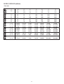
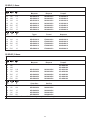
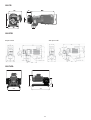
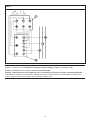
501CC
501cc-gb-02.pdf
9
8
501DF, 501DP, 501DFX, 501DV ATEX II 2 G T4
501F, 501P, 501X, 501V ATEX
2
Declarations
Declaration of
conformity
Declaration of
Incorporation
When this pump unit is used as a stand alone pump it complies with:
Machinery Directive 2006/42/EC, EMC Directive 2004/108/EC.
.
When this pump unit is to be installed into a machine or is to be assembled with other
machines for installations, it must not be put into service until the relevant machinery has
been declared in conformity with the Machinery Directive 2006/42/EC.
Responsible person: David Cole, Managing Director, Watson-Marlow Limited, Falmouth, Cornwall TR11 4RU, England.
Telephone 01326 370370 Fax 01326 376009.
Two year warranty
Watson-Marlow Limited warrants, subject to the conditions below, through either Watson-Marlow Limited, its subsidiaries, or its
authorised distributors, to repair or replace free of charge, including labour, any part of this product which fails within two years of
delivery of the product to the end user. Such failure must have occurred because of defect in material or workmanship and not as
a result of operation of the product other than in accordance with the instructions given in this manual.
Conditions of and specific exceptions to the above warranty are:
• Consumable items such as tubing and rollers are excluded.
• Products must be returned by pre-arrangement carriage paid to Watson-Marlow Limited, its subsidiaries, or its authorised
distributor.
• All repairs or modifications must have been made by Watson-Marlow Limited, its subsidiaries, or its authorised distributors or
with the express permission of Watson-Marlow Limited, its subsidiaries, or its authorised distributors.
• Products which have been abused, misused, or subjected to malicious or accidental damage or electrical surge are excluded.
Warranties purporting to be on behalf of Watson-Marlow Limited made by any person, including representatives of Watson-Marlow
Limited, its subsidiaries, or its distributors, which do not accord with the terms of this warranty shall not be binding upon WatsonMarlow Limited unless expressly approved in writing by a Director or Manager of Watson-Marlow Limited.
Information for returning pumps
Equipment which has been contaminated with, or exposed to, body fluids, toxic chemicals or any other substance hazardous to health
must be decontaminated before it is returned to Watson-Marlow or its distributor.
A certificate included at the rear of these operating instructions, or signed statement, must be attached to the outside of the shipping
carton.
This certificate is required even if the pump is unused. If the pump has been used, the fluids that have been in contact with the pump
and the cleaning procedure must be specified along with a statement that the equipment has been decontaminated.
Safety
In the interests of safety, this pump and the tubing selected should only be used by competent, suitably trained personnel after they
have read and understood this manual, and considered any hazard involved.
Any person who is involved in the installation or maintenance of this equipment should be fully competent to carry out the work. In the
UK this person should also be familiar with the Health and Safety at Work Act 1974.
Fundamental work with regard to lifting, transportation, installation, starting-up, maintenance
and repair should be performed by qualified personnel only. Make absolutely sure that no voltage is applied at all whilst work is being carried out on the geared motor. The motor must be
secured against accidental start up.
Recommended operating procedures
ON
variable speed models please note that the mechanical speed variator must not be adjusted whilst the pump is stationary.
DO
keep delivery and suction lines as short and direct as possible using a minimum number of swept bends
DO
site the pump just above the level of the product to be pumped.
DO
keep the pipework at least equal in size to the bore size of the pump. Increase the bore size when fluids have a high
viscosity or high inertia, thus keeping losses to a minimum.
3
DO
use valves with a straight fluid path.
DO
use slow sweeping bends with minimum radius equal to four to five times the tubing diameter.
DO
keep the pumphead rollers and track clean.
The self-priming nature of peristaltic pumps means valves are not required. Any valves fitted must cause minimum restriction to flow
in the pumping circuit.
When using Marprene tubing, after the first 30 minutes of running, re-tension the tube in the pumphead by releasing the tube clamp
on the delivery side a little and pulling the tube tight. This is to counteract the normal stretching that occurs with Marprene which can
go unnoticed and result in poor tube life.
Tube selection The chemical compatibility list published in the Watson-Marlow catalogue is only a guide. If in doubt about the
compatibility of a tube material and the duty fluid, request a tube sample card for immersion trials.
Installation
Pump
• Site the pump on a flat, horizontal, vibration-proof surface allowing a free flow of air around it. Ensure there is 0.5m of straight
tubing before the pumphead inlet and after the pumphead outlets. Close coupled simplex pumps will require bolting down with four
M8 bolts through the gearbox foot mounting holes.
AC Motor
• Ensure that mains voltage/frequency are in accordance with motor nameplate information.
• Secure protective conductor connections.
• If the motor is running in the wrong direction, interchange any two phases.
• Close unused cable entrance holes and the terminal box itself in a dust and watertight manner.
• A current overload relay should be fitted to a contact breaker. Connect the motor in accordance with the wiring diagram which will
be found in the motor terminal box.
• When a thermal protection switch is fitted in the motor, the leads will be found in the motor terminal box. They should be connected
to stop the pump if the switch operates. The switch will open circuit at an over temperature condition. See below for the connection
of the drive motor showing possible ancillary switches and protections.
1 Emergency stop
2 Start
3 Stop
The ancillary switches are rated to 220/240V 1ph 50Hz. The Start contact should have a sprung return which will disengage following
energisation of the coils C1 and C1/1.
Do not under any circumstances wire switches directly across any of the phases of a 3 phase supply. If in
doubt disconnect the pump immediately!
Do not connect ancillary switches to the terminal box of a flame proof motor unless the switch has a
suitable Exd rating for the zone area in which it is to be mounted.
4
Start up
Before starting and after prolonged storage of the gear units, remove the plug from the vent screw on top of the casing to avoid
excessive pressure in the gearbox, which may cause leakage at the shaft seals.
Troubleshooting
Should the pump fail to operate, make the following checks to determine whether or not servicing is required.
• Check the electrical supply is available at the pump.
• Check that the pump is not stalled by incorrect fitting of tubing.
Always check to ensure that an Exd motor gearbox is suitably rated for the hazardous zone area in which it
is to be mounted. Exd motors should only be installed by Exd qualified personnel.
Any deviation from normal operating conditions (increased power consumption, temperature,
vibrations, noise) or warning signals by monitoring equipment suggest malfunction. Inform the
responsible maintenance personnel at once to prevent the trouble from worsening. If in doubt
disconnect the pump immediately.
AC Motor maintenance
• Remove any dust deposits from the fan cover to avoid overheating.
• Ensure that the bearing cage is packed to about 1/3 with evenly distributed lubricating grease.
• Select the correct lubricating grease from the table in the back of this operating instruction.
Gearbox maintenance - Simplex (single pumphead) units
• Change lubricant every 10,000 working hours or after 2 years.
• Combine a lubricant change with a thorough cleaning of the gear unit.
• Extreme working conditions (high air humidity, aggressive media and large temperature variations) will reduce the interval between
lubricant changing intervals.
• Select the correct lubricating oil from the table in the back of this operating instruction.
Gearbox maintenance - Duplex (twin pumphead) units
The gearbox is filled for life with synthetic lubricant so no maintenance is required.
Belt variator maintenance
• Pulleys are supplied with a permanent grease packing. No refill is necessary. The variator should occasionally be run over its full
range to apply a grease coating to the full track.
• The control spindle should be cleaned and greased occasionally.
Replacement of the V-belt
• Unscrew socket head screws and remove cover with the entire speed control mechanism.
• Remove V-belt
• Wrap new V-belt around open adjustable pulley and let it slip over the spring loaded pulley. The V-belt can be easily attached if the
adjustable pulley is opened. Ensure that the adjustable pulley is opened carefully.
• Replace the removed cover with complete speed control mechanism and re-assemble.
• When positioning the top (adjustable pulley closed) speed limiting lock nut, ensure that the adjustable pulley has a gap of 0.51.0mm to prevent damage to the pulley and motor bearings.
• The V-belt should not be in contact with the bottom of the adjustable pulley.
Air Motors
The air motor is designed for air only. Do not allow corrosive, flammable or explosive gases or
particulate material to enter the motor. Water vapour, oil-based contaminants, or other liquids
must be filtered out. The recommended air pressure should not exceed 7 bar, 100 PSIG.
Always disconnect the air supply before servicing.
5
Installation
A muffler is supplied with the air motor, but not installed. Install a moisture trap and filter in the air line ahead of the motor. If
condensates need to be flushed out of the motor, use clean, dry air at low pressure. For efficiency of output and speed control, use
air lines of the same size or next pipe size larger than the intake port of the motor. A 4 way valve which can be connected by piping
to both air ports of the motor will make reversing possible. Use a pressure regulator or a simple shut off valve to obtain desired power
and conserve air to regulate speed and torque.
Lubrication
Use a detergent SAE #10 automotive engine oil. Lubrication is necessary for all moving parts and rust prevention. We recommend
that an automatic air lubricator be installed in the air line just ahead of the motor. The lubricator should be adjusted to feed one drop
of oil for every 25-35 l/sec, 50-75 CFM, of air going through the motor.
• Manual lubrication-Add 10-20 drops of oil every eight hours of operation through the inlet port while the pump is shut down.
• Automatic lubrication- An In-line oiler should be adjusted to feed one drop per minute for high speed or continuous duty use. Do
not overfeed oil as contamination of the exhaust air may occur.
Troubleshooting
Reason
Low torque
Low speed
Won’t run
Runs hot
Runs good then
slows down
Dirt, Foreign material
Internal rust
Misalignment
Insufficient air pressure
Air line too small
Restricted exhaust
Poor lubrication
Jammed machine
Compressor too small
Compressor too far from unit
x
x
x
x
x
x
x
x
x
x
x
x
x
x
x
x
x
x
x
x
x
x
x
x
x
x
x
x
Pump Specifications
Control range
Voltage/frequency
Power consumption
Operating temperature range
Storage temperature range
Noise
Standards
Machinery Directive
Low Voltage Directive
EMC Directive
See pump specification label
See pump specification label
See pump specification label
5C to 40C
-40C to 70C
<75dB(A) at 1m
IEC 335-1, EN60529 (IP55)
98/37/EC EN60204-1
73/23/EEC EN61010-1
89/336/EEC EN50081-1/EN50082-1
Specific drive performance details such as loaded drive speed variation against mains supply voltage fluctuation and drive stability
from a cold start to normal operating temperature are available on request. For further information please contact Watson-Marlow
Technical Support Centre.
501RLC Pumphead
The 501RLC pumphead has two spring-loaded working rollers, which automatically compensate for minor variations in tubing wall
thickness, giving extended tube life. The 501RLC is set during manufacture to accept tubing with wall thicknesses of between 1.6mm
and 2.0mm, and internal diameters of up to 8.0mm. It is equipped with a “tool lockable” guard for increased safety. This should be
locked shut whilst the pump is in use.
The pumphead can be run clockwise for extended tube life, or anti-clockwise to operate against higher pressures.
501RLC Flow rates
Flow rates for the 501RLC were obtained using silicone tubing with the pumphead rotating clockwise, pumping water at 20C with zero
suction and delivery pressures. For critical applications determine flow rates under operating conditions.
6
501RLC Installation. Simplex (single pumphead) units and duplex (twin pumphead) units
Isolate motor from mains supply.
Fit the track in any one of three orientations, over the drive shaft and locating boss. Secure the track with the four locating screws.
Ensure the drive shaft is degreased before locating the rotor onto the shaft via the split collet. Rotate the rotor until its guide rollers are
aligned flush to the front edge of the track. Tighten the rotor screw to a torque of 3Nm to prevent the collet slipping during operation.
Swing in the crank handle.
To reposition the track, swing out the crank handle to expose the rotor retaining screw. Turn the screw anticlockwise one turn to release
the collet, and withdraw the rotor from the shaft. Remove the four track locating screws, and pull the track clear. Rotate the track to its
new position and tighten the track locating screws.
Photographs show duplex pumps
501RLC Tube loading simplex (single pumphead) units)
Isolate pump from mains supply. Unlock and open the hinged guard and swing out the rotor crank handle until it locks into position.
Select the length of tubing required, noting that approximately 240mm is required for the track systems.
Fit one end of the tubing into one of the spring loaded clamps, and then, whilst rotating the rotor with the crank handle, feed the tubing
between the rollers and the track, aligning it within the rotor tube guides. The tubing must lie naturally against the track and must not
be twisted or stretched. Note: For units with mechanical variators follow the Duplex tube loading procedure.
Fit the other end of the tubing into the second spring loaded clamp, ensuring that the tubing is not slack in the pumphead, since this can
reduce tube life.
Close the crank handle and shut and lock the guard.
The 501RLC pumphead is fitted with four-position tube clamps, to accommodate various tube diameters, which can be adjusted by
pushing in or pulling out the bars at the top of the upper clamp and the bottom of the lower clamp. Set the clamps so that the minimum
necessary pressure is applied to the tubing.
After the pump has been started, open the delivery clamp for a short time, so that the tube can find its natural length.
7
501RLC tube loading. Duplex (twin pumphead) units
Isolate the pump from mains supply. Unlock and open the hinged guard. Swing out the rotor crank handle until it locks into position.
Loosen the rotor screw and give the rotor a sharp tap to release it. Pull the rotor slightly forward from its seated position on the drive
shaft so that the pinned collet clears the drive shaft dog and it can rotate freely . Select the length of tubing required, noting that
approximately 240mm is required for the track systems.
Due to the common gearbox, the two pump rotors run in opposite directions. This means that one rotor
runs in a clockwise direction and the other runs in an anti-clockwise direction. Please consider this and the
effect on the piping arrangements (suction and discharge) during installation.
Fit one end of the tubing into one of the spring loaded clamps, and then, whilst rotating the rotor with the crank handle, feed the tubing
between the rollers and the track, aligning it within the rotor tube guides. The tubing must lie naturally against the track and must not
be twisted or stretched.
Fit the other end of the tubing into the second spring loaded clamp, ensuring that the tubing is not slack in the pumphead, since this can
reduce tube life.
Rotate the rotor until it sits back slightly onto the shaft and guide rollers are aligned flush to the front edge of the track and the pinned
collet is locked to the drive shaft dog. Tighten the rotor screw to a torque of 3Nm to prevent the collet slipping during operation. Clip the
crank handle back into position. Lock the pumphead guard.
After the pump has been started, open the delivery clamp for a short time, so that the tube can find its natural length.
The 501RLC pumphead is fitted with four-position tube clamps, to accommodate various tube diameters, which can be adjusted by
pushing in or pulling out the bars at the top of the upper clamp and the bottom of the lower clamp. Set the clamps so that the minimum
necessary pressure is applied to the tubing.
501RLC Roller adjustment
The 501RLC has a factory set gap of 2.6mm between the rollers and the track and is suitable for tubing having wall thicknesses of
between 1.6 and 2.0mm. Adjustment of the gap will be required if tubing having a wall thickness of less than 1.6mm is required. There
is an adjusting screw on each of the two roller arms, and each of these screws will require adjustment. The correct gap is twice the wall
thickness less twenty percent. Correct adjustment is important: over occlusion will reduce tube life; under occlusion will reduce pumping efficiency.
To change the gap setting, turn each adjusting screw clockwise to increase the gap, or anticlockwise to decrease the gap. A full turn
changes the gap by 0.8mm.To restore the original settings of 2.6mm, turn the adjusting screws until both rollers are just touching the
track, then tighten each screw by three and a quarter turns. The 501RLC2 has a factory set gap of 3.8mm between the wall and the
track and is suitable for tubing having wall thickness of between 2.1 and 2.5mm.
Check moving parts of the rotor from time to time for freedom of movement. Lubricate pivot points and rollers occasionally with Teflon
lubricating oil. For rollers with oilite bushes, use a low viscosity mineral oil in low ambient temperature, or a high viscosity mineral oil for
high ambient temperatures.
8
501RLC Pumphead spares
Number
1
2
3
4
5
6
7
8
9
9
10
10
11
Spare
MN 1200M
FN 4502
FN 2341
MN 0266M
MNA0114A
FN 2332
FN 0422
MN 0011T
MNA0143A
MNA0511A
SG0001
SG0002
MN 0012T
Description
Lockable guard
Lock
Hinge screw
Hinge grey
Tube clamp assembly
Screw
Screw (x 4)
Main roller
501RLC Rotor assembly
501RL2C Rotor assembly
Spring standard (1.6)
Spring hard (2.4)
Follower roller
9
Technical Data
#
English
Tube number
Gearbox lubricant
Mineral Oil
(165)
Tube bore
rpm
Pressure(+)
Energol GR-XP 220
EnergolGR-XP 100
Bartran HV15
Suction
Mobil-gear 630
Mobil-gear 629
Mobil DTE 11M
501F/RL, 501I/RL, 501TI/RL - 100ml
601F/R, 601I/R, 601TI/R - 250ml
Motor wiring
10
Counter-clockwise
(165)
Clockwise (rpm)
Shell Omala Oel 220
Shell Omala Oel 100
Shell Tellus Oel T 15
501RLC, 501RLC2 (ml/min)
Flow rates
#
mm
“
112
0.5
1/50
13
0.8
1/32
14
1.6
1/16
16
3.2
1/8
25
4.8
3/16
17
6.4
1/4
18
8.0
5/16
60
213
291
2.5
8.9
12
7.4
26
36
26
91
120
110
400
540
240
860
1200
380
1400
1900
600
2100
2900
62
223
281
2.6
9.3
12
7.6
27
34
26
95
120
120
410
520
250
900
1100
390
1400
1800
620
2200
2800
6 - 60
0.25-2.5
0.74-7.4
2.6-26
11-110
24-240
38-380
60-600
21 - 213
0.88-8.9
2.6-26
9.0-91
39-400
85-860
130-1400
210-2100
29 - 291
6 - 62
1.2-12
0.25-2.6
3.6-36
0.74-7.6
12-120
2.6-26
54-540
11-120
120-1200
24-250
180-1900
38-390
290-2900
60-620
22 - 223
0.92-9.3
2.7-27
9.4-95
41-410
89-900
140-1400
220-2200
28 - 281
12 - 60
43 - 213
1.2-12
0.50-2.5
1.8-8.9
3.4-34
1.5-7.4
5.3-26
12-120
5.1-26
18-91
52-520
22-110
80-400
110-1100
48-240
170-860
180-1800
76-380
270-1400
280-2800
120-600
430-2100
13 - 64
0.54-2.7
1.6-7.9
5.6-27
24-120
53-260
83-410
130-640
40 - 201
1.7-8.4
4.9-25
17-86
74-370
160-810
250-1300
400-2000
11
501RLC, 1.6mm
Product codes
mm
0.5
0.8
1.6
3.2
4.8
6.4
8.0
“
1/50
1/32
1/16
1/8
3/16
1/4
5/16
#
112
13
14
16
25
17
18
Marprene
902.0005.016
902.0008.016
902.0016.016
902.0032.016
902.0048.016
902.0064.016
902.0080.016
Bioprene
903.0005.016
903.0008.016
903.0016.016
903.0032.016
903.0048.016
903.0064.016
903.0080.016
Pumpsil
913.0005.016
913.0008.016
913.0016.016
913.0032.016
913.0048.016
913.0064.016
913.0080.016
mm
0.8
1.6
3.2
4.8
6.4
8.0
“
1/32
1/16
1/8
3/16
1/4
5/16
#
13
14
16
25
17
18
Tygon
Fluorel
950.0016.016
950.0032.016
950.0048.016
950.0064.016
950.0080.016
970.0016.016
970.0032.016
970.0048.016
970.0064.016
970.0080.016
Neoprene
920.0008.016
920.0016.016
920.0032.016
920.0048.016
920.0064.016
920.0080.016
#
Marprene
Bioprene
119
120
15
24
121
902.0016.024
902.0032.024
902.0048.024
902.0064.024
902.0080.024
903.0016.024
903.0032.024
903.0048.024
903.0064.024
903.0080.024
501RL2C, 2.4mm
Product codes
mm
0.5
0.8
1.6
3.2
4.8
6.4
8.0
“
1/50
1/32
1/16
1/8
3/16
1/4
5/16
mm
“
#
Chem-Sure
Sta-Pure
1.6 1/16
119
965.0016.024
960.0016.024
3.2 1/8
120
965.0032.024
960.0032.024
4.8 3/16
15
965.0048.024
960.0048.024
6.4 1/4
24
965.0064.024
960.0064.024
8.0 5/16
121
965.0080.024
960.0080.024
Note: 2.4mm wall Chem-Sure and Sta-Pure tubing are supplied in 355mm lengths
12
Pumpsil
913.A005.024
913.A008.024
913.A016.024
913.A032.024
913.A048.024
913.A064.024
913.A080.024
501RLC
Flow rates
13
501F/R
501DF/R
62rpm model
223 rpm model
501FX/RL
345
85
75
230
250
220
340
14
Switch
Watson-Marlow, Bioprene, Pumpsil and Marprene are trademarks of Watson-Marlow Limited.
Tygon is a trademark of the Saint-Gobain Performance Plastics Company. Fluorel is a trademark of 3M.
Sta-Pure and Chem-Sure are trademarks of W.L Gore and Associates.
Warning, These products are not designed for use in, and should not be used for patient connected applications.
The information contained in this document is believed to be correct but Watson-Marlow Limited accepts no liability for any
errors it contains, and reserves the right to alter specifications without notice.
15
16
Product use and decontamination declaration
In compliance with the UK Health & Safety at Work Act and the Control of Substances Hazardous to Health
Regulations you, the user are required to declare the substances which have been in contact with the product(s) you
are returning to Watson-Marlow or any of its subsidiaries or distributors. Failure to do so will cause delays in servicing
the product. Therefore, please complete this form to ensure that we have the information before receipt of the
product(s) being returned. A FURTHER COPY MUST BE ATTACHED TO THE OUTSIDE OF THE PACKAGING
CONTAINING THE PRODUCT(S). You, the user, are responsible for cleaning and decontaminating the
product(s) before returning them.
Please complete a separate Decontamination Certificate for each pump returned.
RGA No: .......................
1
Company
Address
........................................
Postcode ........................................
Telephone
........................................
Fax Number ....................................
3.4 Cleaning fluid to be used if residue of chemical is found during
servicing;
2 Product
2.1 Serial Number ................................
(a)
2.2 Has the Product been used?
YES
(b) ……………………………………………
(c) ……………………………………………
NO
(d) ……………………………………………
If yes, please complete all the following
Sections
If no, please complete Section
5 only
3 Details of substances pumped
3.1 Chemical names:
4 I hereby confirm that the only substances(s) that the equipment
specified has pumped or come into contact with are those named, that the
information given is correct, and the carrier has been informed if the
consignment is of a hazardous nature.
(a) ....................................................... 5 Signed ……………………………………………….. ...........
(b) .......................................................
(c) .......................................................
(d) .......................................................
Name …………………………………………………
Position ……………………………………………….
Date …………………………………………………..
3.2 Precautions to be taken in
handling these substances:
(a) ........................................................
(b) ....................................................................................................... Note: To assist us in our servicing
please describe any fault condition you
(c) ........................................................
have witnessed.
(d) ........................................................
3.3 Action to be taken in the event of human contact:
(a) ………………………………………………………………….
(b) ………………………………………………………………….
(c) ………….………………………………………………………
(d) ………….………………………………………………………
Watson-Marlow Limited Falmouth Cornwall TR11 4RU England Tel: 01326 370370 Fax: 01326 376009
17