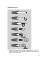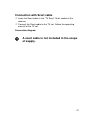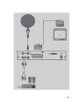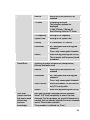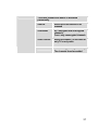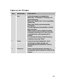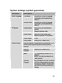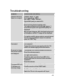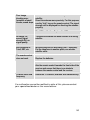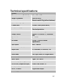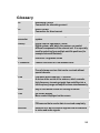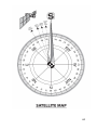
1
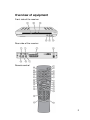
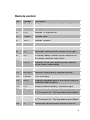
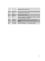
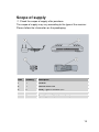
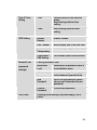
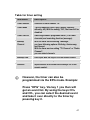
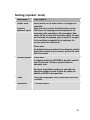
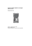
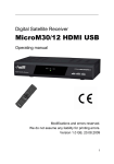
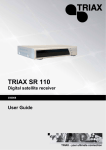
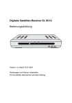
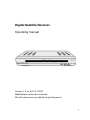
Digital Satellite Receiver
Operating manual
Version 1.0, as of 21/11/2007
Modifications and errors reserved.
We will not assume any liability for printing errors.
1
Overview of equipment
Front side of the receiver
Rear side of the receiver
Remote control
2
Overview of equipment
Front side of the receiver
1
-
2
LED STBY
3
LED ON
4
Standby
5
CH+ key
6
CH- key
Infrared sensor for the signals of the
remote control
LED is only illuminated if the receiver is in
standby mode
LED is illuminated if the receiver is
switched on
Switches on and switches to the standby
mode
Switches to the next higher channel
location
Cursor moves up
Switches to the next lower channel
location
Cursor moves down
Rear side of the receiver
1
2
LNB IN
IF OUT
3
4
5
6
7
TV (output)
DC IN 12V
AUDIO R
AUDIO L
Video
LNB connection for the antenna cable
LNB connection for an analogue satellite
receiver in standby mode
SCART connection for the TV set
Connection 12V/power pack
Analogue audio connection R(Right)
Analogue audio connection L(Left)
RCA video connection
3
Remote control
No.
Symbol
Description
1
Standby
Switches on and switches to the standby mode
2
ZOOM
Enlarges TV image
3
LIST
Invokes TV channel list
4
TIMER
Invokes timer
5
TEXT
Invokes Teletext
6
MUTE
Turns off sound
7
M/P
Multi-picture function, invokes thumbnail view
8
V+
Increases volume/cursor moves to the right
9
OK
In normal mode: invokes current channel list
In a menu: confirms menu item
10
CH ▼
Switches to the next lower channel location/
cursor moves downwards
11
FAV
Invokes own favourites list
12
RECALL
Switches to previously selected channel
13
PAUSE
Stills the frame
14
INFO
Displays reception data of the current channel
(satellite-finder function)
15
0-9
Selects channel directly, numerical input
16
P-
In normal mode: change of channel group
In TV channel list: Ten-key block commutation
17
P+
In normal mode: change of channel group
In TV channel list: Ten-key block commutation
18
V-
Decreases volume/cursor moves to the left
4
19
CH ▲
Switches to the next higher channel
location/cursor moves up
20
MENU
Invokes main menu
21
EXIT
Exits menu or menu item
22
Audio
Changes audio mode
23
EPG
Invokes Electronic Programme Guide (if offered
by the broadcasting station)
24
TV/SAT
Switches between terrestrial and satellite
antenna
25
TV/Radio
Switches between TV and radio mode
5
Preface
This operating manual will help you in the
• appropriate
• safe
Usage of the digital satellite receiver, hereafter called as the
receiver in short.
We assume that the user of the Sat-System has overall knowledge
regarding handling of audio and video equipment.
Every person who
• installs,
• connects,
• operates,
• cleans
• disposes of
This receiver must be familiar with the entire content of this
operating manual. Always keep this operating manual in the
proximity of the satellite system.
Style features
Specific style features have been given in different sections of the
operating manual. Thus, you can easily differentiate whether it
concerns
Normal text,
• enumerations or
Actions.
6
Contents
Overview of equipment....................................................................... 3
Remote control ................................................................................... 4
Preface............................................................................................... 6
Style features .................................................................................... 6
Contents ............................................................................................ 7
Safety instructions ........................................................................... 9
Basic safety instructions............................................................. 9
Appropriate usage ............................................................................ 12
Scope of supply.............................................................................. 13
Description ...................................................................................... 14
Receiver connection ...................................................................... 18
LNB cable installation ....................................................................... 19
Connection with Scart cable ............................................................. 21
Connection with Cinch cable ............................................................ 23
Connection of an audio-digital receiverFehler! Textmarke nicht definiert.
Direction of the antenna ................................................................... 25
Getting started ................................................................................ 26
Remote control ................................................................................. 26
Receiver............................................................................................ 27
Adjustment of antenna...................................................................... 28
Operation......................................................................................... 29
Screen-inlays while switching a channel .......................................... 29
User interface on the TV monitor ..................................................... 30
Menu Structure ................................................................................. 31
Menu navigation ............................................................................... 32
Channel (symbol: TV)....................................................................... 33
Installation (symbol: satellite antenna) ............................................. 35
System settings (symbol: gearwheel)............................................... 39
Setting (symbol: tools) ...................................................................... 42
Software update via satellite............................................................. 43
Keys with special functions .......................................................... 44
7
Switch between TV and SAT............................................................ 44
Switch between TV and radio........................................................... 44
ZOOM ............................................................................................... 44
LIST .................................................................................................. 44
AUDIO .............................................................................................. 45
EPG .................................................................................................. 45
Teletext ............................................................................................. 45
M/P Multipicture ................................................................................ 46
MUTE................................................................................................ 46
FAV................................................................................................... 46
RECALL............................................................................................ 47
Acoustic signal for directing the satellite antenna ............................ 47
Sleep timer ....................................................................................... 47
Pause................................................................................................ 47
Dismantling ..................................................................................... 48
Cleaning........................................................................................... 48
Troubleshooting ............................................................................. 49
Technical specifications ................................................................ 51
Manufacturer ................................................................................... 53
Guarantee ........................................................................................ 53
Declaration of conformity .............................................................. 54
Glossary .......................................................................................... 55
Information regarding alignment of dish (UK)..........................56
8
Safety instructions
Please read the safety instructions carefully before operating the
receiver.
Please follow all warnings and instructions on the equipment and in
the operating manual.
Basic safety instructions
Electrical connection
• Do not expose the receiver to rain as well as any kind of
humidity to avoid risk of fire and electric shock.
• Never open the casing. Otherwise, there is a risk of electric
shock.
• Connect the receiver only to the power source installed by an
expert. It is either:
- for an external power pack:
A 100–240 V, 50-60 Hz mains socket as per specifications or
- for a 12 V cable:
An 11 V / 15 V DC supply as per specifications.
• Ensure that the total power consumption by the antenna
connection of the receiver does not exceed “LNB IN” 300 mA.
• Pull the external power pack or the 12 V cable out of the mains
socket if you will not use the device for a longer period of time.
Only pull at the external power pack or at the head piece of the
12 V cable, not at the cable itself.
• In case of a storm, pull the external power pack or the 12 V
cable of the receiver out of the mains socket.
• If foreign bodies or fluids enter the receiver, pull the external
power pack or the 12 V cable out of the mains socket. Ask a
qualified person to check the equipment before operating it
once again. Otherwise, there is a risk of electric shock.
• Do not bend or crimp any cable.
• If a cable used for mains supply is damaged, the receiver must
be repaired by an expert before re-using it. Otherwise, there is a
risk of electric shock.
9
• Never allow children to operate the receiver or to play with the
antenna unit unless supervised.
• Always ask qualified personnel to carry out maintenance jobs.
Otherwise, you are putting yourself and others at risk.
• Disconnect the receiver from the power source in case of
operational disruptions.
• Ensure that the power source is easily accessible.
Correct position
• Place the receiver on a stable and even base.
• Use the receiver only with adequate climatic conditions.
• Avoid proximity to:
- heat sources, e. g. heaters,
- naked flames, e. g. candles,
- Devices with strong magnetic fields, e. g. loudspeakers.
- Never place receptacles filled with liquid (vases) on the
receiver
• Avoid direct sunlight and places with an extremely high amount
of dust.
• Never cover ventilation slits. Provide for sufficient ventilation by
maintaining a safety distance of 5 cm to other objects.
• Do not place any heavy objects on the receiver.
• Humidity may settle in the receiver if it is brought into hot
surroundings from a cold one. In this case, wait for about an
hour before operating the equipment.
• Arrange all cables in such a manner that no-one steps or trips
over them.
• The antenna unit is not suitable for operating in case of high
wind pressures. Do not expose it to strong wind.
Correct battery handling
• Batteries may contain toxic agents. Ensure that batteries are
not within the reach of children. Children may eat and swallow
batteries.
10
• Batteries that are getting discharged may damage the remote
control. If the receiver is not in use for a longer period of time,
remove the batteries from the remote control.
• Batteries may contain toxic agents. Therefore, dispose of the
batteries immediately in an ecologically accepted manner
according to the prevailing statutory regulations. Never throw
the batteries into normal household waste.
• Never expose the batteries to open fire or strong heat, as there
is a danger of explosion.
• Replace the batteries always with batteries of the same type.
Explanation of safety instructions
The following categories of safety instructions are included in the
operating manual:
Danger!
Instructions with the word DANGER give a
warning against possible personal injuries.
Caution!
Instructions with the word CAUTION give a
warning against possible material or
environmental damages.
These instructions contain special
information for commercial usage of the
satellite system.
11
Appropriate usage
The receiver receives unencoded digital channels (free-to-air) in a
covered area. It is exclusively meant for this purpose and should
only be used for the same. This also includes paying attention to all
information in this operating manual especially that of safety
instructions.
Any other usage is considered to be improper and may lead to
material damages and even personal injuries. Moreover, it will
result in the immediate loss of warranty.
The manufacturer does not bear any liability for damages caused
due to improper usage.
12
Scope of supply
Check the scope of supply after purchase.
The scope of supply may vary according to the type of the receiver.
Please follow the information on the packaging.
Item
Quantity
Description
1
1
Receiver
2
1
Remote control unit
3
2
Battery Type LR 03/AAA/1,5 V
4
1
External power pack
1
Operating manual (not shown above)
13
Description
You can receive unencoded (free-to-air) digital satellite channels
with this receiver.
It is not necessary to programme the receiver yet. The most
important broadcasting stations and satellites have already been
pre-programmed.
The following satellites have been pre-programmed by the
company:
• Astra1 19° East
• Hotbird 13E
• Turksat 42E
• Sirius2 5E
• Amos 4W/Atlantic4-5W
• Astra2 28° East (UK English satellite)
• Eutel W2 16E
• AtlanticBird3 5W (former France Telecom 2D)
• HispaSat 30W
• HellasSat 39E
• ASTRA 23.5E
The satellite antenna has to be directed towards the desired
satellite.
The receiver will scan for further new broadcasting stations as
soon as you initiate the automatic scanning of broadcasting
stations for this satellite. Satellites which are not pre-programmed
may be added.
All receiver settings can be done easily using the user interface
(menu) on the TV monitor.
The multilingual user interface supports the following
languages:
• German
14
• Greek
• Croatian
• Czech
• Danish
• Dutch
• Hungarian
• Norwegian
• Polish
• Slovakian
• Swedish
• Slovenian
• English
• French
• Turkish
• Spanish
• Italian
• Portuguese
Other features of the equipment:
• Software updates via satellite ASTRA 19° East
• Short switching time, fast boot process when switching on the
receiver
• Saves the channel last watched (Last Station Memory)
• LNB control logic (sound 0/22 kHz), max. current delivery for
LNB 300 mA
• Symbol rate 1-35 MS/s and 950-2150 MHz input frequency
• Manual PID entry possible
• 3 keys at the frontage
• Plug & play
• External power pack 100–240 V, 50/60 Hz, output 12V; 0.75A
• 4.500 channel storage locations
15
• Child lock (preset password: 0000)
• 1 favourites list and 8 channel groups
• Automatic scanning of broadcasting stations
• List editor for broadcasting stations
• Analogue sound output through Cinch connector (stereo),
volume adjustment possible via remote control
• 1 Euro-SCART connection for TV and video set
• Video output signal CVBS
• Loop-through-function in standby mode for the connection of an
analogue receiver
• Super fast videotext with a memory of 800 pages
• Digital radio reception, background image for radio (background
display)
• Additional channel information is displayed when the channel is
changed.
• DiSEqC 1.0, 1.2, Go-to X is supported if an appropriate antenna
unit is connected
• SWAP function (via Recall key)
• Screen aspect ratios can be set to 4:3, 16:9, and automatically
(letterbox)
• Multi-functional timer, 8 x and linked with EPG, sleep timer
• Electronic Programme Guide EPG (up to 14 days in advance,
channel-dependent)
• SCPC/MCPC reception standard C/Ku-Band satellites
• Automatic selection of the TV standard with video converter
• Zoom function
• Multi-picture function
16
• Digital satellite finder for optical and acoustic adjustment of the
parabolic-type reflector
A suitable channel editor is additionally
available through our hotline. Then you
will be able to edit the channel lists of the
receiver using your computer. Please read
the information on our website for this
purpose.
17
Receiver connection
The receiver is connected with your satellite antenna by means of
a coaxial cable. If necessary, you have to prepare a coaxial cable
before connecting the receiver.
Caution!
Connect the receiver to the mains supply only
after you have connected it to all equipment
and the antenna properly. Otherwise the
receiver can suffer damages.
The wire netting and the inner core of the
coaxial cable carry current during operation.
Usage for camping or in caravans:
The receiver can also be operated with
12V (i.e. 11-15V, e.g. solar panel). For this
purpose, use a 12V cable.
Usage with a voltage of 24V (e.g.: freight
vehicles):
Please use a 24V / 12V DC/DC converter.
18
LNB cable installation
(see the installation diagram on the next page)
For the installation of the F connectors on the coaxial cable you
need a knife (ideally a wire stripper) and side cutting pliers.
Cut 8 mm of the coaxial cable at each end up to the inner core.
Carefully cut 10 mm of the outer insulation so that the wire
netting is exposed.
Turn the wire netting backwards and wind it over the outer
insulation in such a manner that it does not touch the inner
core.
Remove the inner insulation up to 2 mm from the wire netting.
Rotate the IF connector onto the turned-back wire netting till the
connector touches the inner insulation.
The wire netting must not protrude from
the back of the connector end.
Cut the inner core with a cable cutter in such a manner that it
projects maximum 1 mm from the connector.
19
Installation diagram
Fasten the F connector of the coaxial cable onto the “LNB IN”
antenna connection of the receiver. Fasten the other end of the
coaxial cable to the LNB.
20
Connection with Scart cable
Insert the Scart cable in the “TV Scart” Scart socket of the
receiver.
Connect the Scart cable to the TV set. Follow the operating
manual of the TV set.
Connection diagram
A scart cable is not included in the scope
of supply.
21
22
Connection with Cinch cable
Connect the Cinch connectors of the Cinch cable to the “AUDIO
R” and “AUDIO L” sockets of the receiver if you want to connect
a stereo system.
Please also connect the “VIDEO” output to your TV Set to have
the picture via Cinch.
Caution!
Never connect the Phono input of your stereo
system to the receiver; it may damage your
stereo system.
Strictly follow the instructions for connecting
the Cinch cable given in the operating manual
of your stereo system.
The Cinch cable is not included in the
scope of supply.
23
Connection diagram
24
Direction of the antenna
You must connect the LNB cable to LNB before directing the
antenna.
Caution!
While connecting the LNB cable, the receiver
must not be connected to the mains supply.
Fasten the F-connector onto the connection of LNB on which
the sealed socket is located.
Insert the sealed socket into the LNB connection. The sealing
lip of the socket must be engaged with the connection; only
then is the connection protected from humidity.
After installation, direct the antenna towards the satellite
through which you would like to receive signals. Use the
satellite locator compass for this purpose. Proceed as described
in the operating manual of your satellite system. For UK see
page 57.
For fine adjustment of the antenna, please
proceed as described in the operating
manual of your satellite system.
During the fine adjustment of the antenna,
the acoustic signal indication can also
help you. However, it can only be
activated when running a manual scan.
Here, a high tone indicates a good
antenna direction, while a low tone
indicates a bad antenna direction.
25
Getting started
Remote control
Two Micro type batteries are required for the remote control:
LR 03/AAA/1.5 V
Open the battery compartment.
Insert two batteries into the battery compartment paying
attention to the indicated polarities and push the cover of the
battery compartment carefully until the cover is locked.
Replace discharging batteries immediately.
Always replace both batteries simultaneously and use batteries
of the same type.
If any battery has leaked, wear protective gloves and clean the
battery compartment with a dry cloth.
Caution!
Batteries may contain toxic agents that are
hazardous to health and environment.
Therefore, dispose of the batteries immediately
according to the prevailing statutory
regulations. Never throw the batteries into
normal household waste.
The remote control transmits infrared signals to the receiver.
Please refer to the overview of the remote control for the
functioning of the keys.
Point the remote control towards the front side of the receiver
and slightly press the corresponding key once.
26
Receiver
Caution!
Check the proper connection of all devices and
of the antenna before connecting the external
power pack or the 12 V cable of the receiver to
the power source and starting the receiver.
Insert the mains plugs of the connected equipment in the mains
socket and switch it on..
Switch on the AV channel of the TV set.
Insert the power pack of the receiver in the mains socket. The
device is in normal mode. The green LED is lit.
If you wish to operate the receiver with 12V, insert the 12V
mains cable in the “DC IN“ socket and connect it to your power
source.
The receiver is supplied with pre-programmed TV channels and
can be used directly. If you want to check if new channels are
available, initiate a scan for broadcasting stations. Read the
information further below for this purpose.
To get into standby mode, press the red
key at top right of the remote control. The
red LED of the receiver is lit.
27
Adjustment of antenna
The reception quality set by you in the antenna settings may not be
optimal. In this case, you must do a fine adjustment of the antenna.
For this procedure, please see the operating manual of your
satellite system. For UK see page 57.
By pressing the “INFO” key, the current
reception parameters are displayed.
Please keep in mind that the signalstrength indication only shows the
connection quality of the antenna to the
receiver and is not intended to be used for
the direction of the antenna.
By pressing the 1 key, an acoustic signal
is offered additionally to support you
during the fine adjustment. A stronger and
higher signal indicates a better direction
of the antenna.
As soon as the signal quality has reached approx. 60%, the
channel image appears in the background. Should there be no
image, you might have directed the antenna to another satellite
instead of Astra1 19°. In this case, please find in the operating
manual of your satellite system how to proceed.
28
Operation
Screen-inlays while switching a channel
When a channel is switched, an information bar is inlayed on the
screen for 5 seconds (adjustable).
In this information bar, you will find the following indications:
Channel name
Received satellite
Current date
Current time
Storage location
TXT symbol
This symbol is displayed if the selected broadcasting
station offers Teletext.
EPG symbol
This symbol is displayed if the selected broadcasting
station offers a programme guide.
Heart
symbol
The heart symbol is displayed if you have included the
channel in your favourites list.
Channel
group
symbol
The corresponding channel group symbol is displayed if
you have included the channel in your channel list.
Info
Information on the current and the following programme
Info
Information on the currently active channel list
29
User interface on the TV monitor
You can do individual settings of your receiver using the menus in
the user interface. For this purpose, both the receiver and the TV
set need to be switched on and connected by a cable (SCART or
CINCH).
Press the “MENU” key. The main menu will be displayed. By
pressing the “EXIT“ or the “MENU“ key, you can exit this menu
again.
Orientation within the menus
At the top:
menu name
(the corresponding function symbols are displayed
at the bottom)
Below:
sub-menu or menu items
At the bottom: The information bar indicates the keys with which
you can move yourself within the current menu.
30
Menu Structure
Main menu
Sub-menu
Description
Language
(symbol
corresponding
country flag)
Language selection
Selection of the language
in which the OSD menu is
to be displayed.
Channel
(symbol:
TV)
TV Channel List
See following text
Radio Channel List
See following text
Delete All
See following text
Installation
(symbol: satellite
antenna)
Antenna Setup
See following text
TP Scan
See following text
Preset Scan
See following text
Auto Scan
See following text
Audio Language
See following text
TV System
See following text
Channel setup
See following text
Time & Timer setting
See following text
OSD Setting
See following text
Parental Lock
See following text
LNB Power
See following text
Default Value
See following text
Software-Update
See following text
Game
See following text
Information
See following text
System Setup
(symbol: Receiver)
Tools
(symbol
tool case)
31
Menu navigation
Use the keys “CH+”, “CH-”, “V+”, and “V-” to navigate within the
menus. The selected menu items are marked. Confirm your
selection with the “OK” key. By pressing the “EXIT” key you can
exit the menu again. Changes must be confirmed additionally.
Apart from this, the numerical keys are required in further submenus.
In each menu, an information bar will be
indicated containing all selection options.
Example: Resetting the receiver to daylight saving time.
Press the “MENU“ key, select system settings, then go to date &
timer setting, press the “OK” key, select time and press the “OK”
key again. Set “GMT+02:00“ in the item GMT difference. Exit the
menu by pressing the "EXIT“ key.
Setting for Central Europe:
Daylight saving time: GMT+02:00
Winter time: GMT+01:00
32
Channel (symbol: TV)
Sub-menu
Description
TV channel list
1 Favourite, 2 Move, 3 Find, 4 Sort, 5 Edit, 6
Type, ▲▼Select, V- V+ Group, OK Enter, EXIT.
Radio channel
list
as indicated above
Delete all
Deletion of the complete channel list.
For this purpose: Enter password (factory setting
0000) and confirm warning message with Yes.
1 Favourite
By pressing key 1 you can determine your favourites. Next to the
corresponding channels, a heart symbol will be displayed.
2 Move
By pressing key 2, the movement symbol will appear behind the
marked channel. By pressing the keys CH+ and CH-, the channel
will be moved to the desired position. The procedure must be
confirmed with OK.
3 Find
Channel scan function. By entering letters in the appearing
keyboard, a filtered channel scan is possible.
4 Sort
Sorting of the complete channel list according to the offered
options. The list must be confirmed with OK. As long as the list has
not been confirmed, the last status before confirming can be
restored.
33
5 Edit
After entering the password (factory setting 0000), new selection
options will appear.
Sub-menu
Description
Edit
1 Delete, 2 Skip, 3 Lock, 4 Create,
5 Edit, 6 Del all, ▲▼Select, V- V+ Group, P+PPage, EXIT Exit.
1 Delete
By marking with key 1, selected channels can be marked to be deleted. Please
confirm selection by pressing the "OK“ key.
2 Skip
By marking with key 2, selected channels can be marked to be skipped. Please
confirm selection by pressing the "OK“ key. Then, the selected channels are
skipped when zapping. A direct entry is still possible.
3 Lock
By marking with key 3, selected channels can be marked to be blocked. Please
confirm selection by pressing the "OK“ key. Then, the selected channels require the
entry of a password (child lock).
4 Create
Via key 4 you will change over to the editing mode. Here, you can change the
individual parameters as desired. Please confirm selection by pressing the "OK“
key.
5 Edit
Via key 5 you will change over to the new entry mode. By entering the frequency
and PID directly, you can enter a new channel.
6 Del(delete) all
Via key 6 you can mark all channels to be deleted. Thereafter, individual channels
can be deselected again by pressing key 1. Please confirm selection by pressing
the "OK“ key.
34
6 Type (channel group)
Here, you can assign selected channels to determined channel
groups (Types) as desired. Please confirm your selection with
“OK”. You can exit the menu by pressing the "EXIT“ key.
Installation (symbol: satellite antenna)
Sub-menu
Description
Antenna setup
Satellite
Satellite selection
(example: Astra1 19.2° East)
LNB Type
Select LNB type
(default value is Universal)
22K
22KHz activation,
(Note: with LNB type Universal,
activation occurs automatically)
DiSEqC
Select DiSEqC level
DiSEqC
Switch
Select DiSEqC command
Example:
Astra and Hotbird double reception
Astra = 1 / 4
Hotbird = 2 / 4
Disable for positioner: Not enabled
Positioner
By pressing the “OK“ key you will
go to DiSEqC positioner menu.
Please refer to the operating
manual of your DiSEqC motor for
help.
Polarity
Horizontal, vertical, H/V (automatic
operation)
TP Scan
(manual
channel scan)
With this scanning function, you can scan the preset
frequencies (transponders) individually. The
transponder details can be changed manually.
The procedure is initiated with “Scan“.
35
Preset Scan
Auto Scan
(unique function
that can be used
without any
previous
knowledge),
Satellite
Selection of the satellite to be
scanned
TP Index
Frequency selection
The selection options are
displayed
1 Add, 2 Delete, 3 Delete all
See following table for TP Index.
TP Frequency
Setting of the frequency
Symbol Rate
Setting of the symbol rate
Polarity
H = horizontal, V = vertical
Scan Mode
all = encrypted and unencrypted
channels
Free = only unencrypted channels
Search
Start scan by pressing the OK key.
The channels and frequency found
are added.
Scanning of preset frequencies (transponders).
(Normal automatic scan)
Satellite
Selection of the satellite to be
scanned
Scan Mode
all = encrypted and unencrypted
channels
Free = only unencrypted channels
Scan Channel
Selection between TV and radio or
only TV or only radio
Search
Start scan by pressing the OK key.
Here you can scan a selected satellite (example:
Astra1 19.2° East) completely to search for new
channels. For this purpose, no special information is
needed. You can choose between free-to-air channels
and all TV and radio channels.
The procedure is initiated via “Scan”.
36
The signal strength and quality is displayed
permanently.
Satellite
Selection of the satellite to be
scanned
Scan Mode
all = encrypted and unencrypted
channels
Free = only unencrypted channels
Scan Channel
Selection between TV and radio or
only TV or only radio
Search
Start scan by pressing the OK key.
The channels found are added.
37
Table for the TP Index
No.
Sub-menu
Description
1
Add
Create new frequency (transponder):
Menu item "TP frequency": Frequency: set
desired frequency
Menu item "Symbol rate": set corresponding
symbol rate
Menu item Polarity: set corresponding
polarisation
The new frequency (transponder) is created
after execution.
When exiting the menu confirm the safety
message by pressing the OK key. Only after
confirmation the new frequency will be
created.
For scanning the newly created frequency,
initiate the menu item "Scan".
2
Delete
Delete the selected transponder. When
confirming the safety message, the
transponder and all channels on it will be
deleted.
3
Del(ete) all
When confirming the safety message, all
transponders and all channels on them will be
deleted.
38
System settings (symbol: gearwheel)
Sub-menu
Description
Audio Language
First Audio
Preselection of audio language
(if offered by the broadcasting
station)
Second Audio
Preselection of audio language
(if offered by the broadcasting
station)
Display Mode
Selection of the transmission
system
Default selection: Auto
Aspect Mode
Selection of the aspect ratio
Default selection: 4:3 Letterbox
Video Output
CVBS
Dolby Digital
Enable (On) / disable (Off)
TV System
Channel setup
Start-up channel: Determination of the desired TV or
radio channel appearing when switching on the
receiver
Start-up
Channel
Enable (On) / disable (Off)
Mode
TV = the start-up channel is a TV
channel
Radio = the start-up channel is a
radio channel
Start-up
Channel:
By pressing the OK key, a channel
list will be displayed for selecting
the start-up channel. Confirm the
selected channel by pressing the
OK key.
39
Time & Timer
Setting
OSD Setting
Time
Optional input of time and time
zones.
See following table for time
setting.
Timer
See following table for timer
setting.
Subtitle
Display
Enable / disable
OSD Timeout
Menu display time (OSD time lock)
OSD
Transparency
Menu transparency
Load Default
OSD Setting
OSD default value can be restored
Parental Lock
Factory password: 0000
(password
settings)
Installation
Lock
Deactivation of password input in
the Installation menu
Channel Lock
Deactivation of password input for
locked channels (parental lock)
New
Password
Input of a new password. (Make
sure you will remember the new
password)
Confirm
Password
Confirm new password.
LNB Power
Enabling and disabling LNB power supply. ON is
preset.
40
Table for timer setting
Sub-menu
Description
Timer Number
Selection of timer number 1-8.
Timer Mode
Type of repetition (once, daily, weekly, monthly,
annually, off). With the setting “Off“, the timer will be
disabled.
Timer Service
Switching between programme timer (TV or radio
channels) and reminding function (message).
Wakeup
Channel
With the timer service setting “Message“,
you have following options: Birthday, Anniversary,
and General
With the timer-service setting "TV Channel“ or "Radio
Channel“,
you can select channels
Wakeup Date
Date input with the keys 0-9 of the remote control
On Time
Time input with the keys 0-9 of the remote control
Duration
Input duration of the event with the keys 0-9 of the
remote control.
However, the timer can also be
programmed via the EPG mode. Example:
Press “EPG“ key. Via key 1 you then will
get an event list. By using the keys CH+
and CH-, you can select the desired event
and take it over directly to the timer by
pressing key 2.
41
Setting (symbol: tools)
Sub-menu
Description
Default Value
Reset receiver to the default value. All changes are
cancelled.
If the receiver is reset to the default values via the
OSD menu, the language selection appears in the
main menu after completion of the procedure. Now,
switch off the receiver with the mains switch. As soon
as 5 seconds have passed, you can switch it on again.
In the condition as supplied to the customer, the
receiver starts in normal mode.
(requires
password input)
Please note:
the default values are restored if you keep the standby
key at the front side of your receiver pressed for more
than 10 seconds.
Software-Update
Please note:
A software update has NOTHING to do with a scan for
new TV channels. Therefore, please initiate an
automatic scan.
By means of a software update you can load new
operation software in case of need. An update via
satellite or RS232 is also possible.
Game
Here, the three games Tetris, Snake and Othello are
available.
Information
Technical details
42
Software update via satellite
The update has nothing to do with the
storage of new TV channels. It is rather
meant to update the system software of
the receiver.
Normally, the update is not required for a
trouble-free operation of the receiver.
You must direct your satellite system
towards the satellite ASTRA 19° East to be
able to update the software.
Updating the software may take up to an
hour.
After the upgrade, it is recommended to load the factory settings
additionally. PLEASE NOTE: with this, the channel list you created
will be deleted.
43
Keys with special functions
Switch between TV and SAT
With the “TV/SAT” key you can switch between TV and satellite
functions. (This function has to be provided by your TV set).
Press the “TV/SAT” key until you have set the desired function.
Switch between TV and radio
With the “TV/Radio” key you can switch between TV and the radio
function.
Now, the receiver transmits a radio channel and shows a
background image.
To return to the TV channel, press the “TV/Radio” key of the
remote control.
ZOOM
With the zoom function you can enlarge a section of the image.
Press the “ZOOM” key twice.
Select the image section with the keys CH-, CH+, V- and V+.
With each pressing of the “ZOOM” key, a section of the image will
be enlarged up to a maximum of 6 x. With the seventh key
pressure, the image will return to its original size. By pressing the
“EXIT” key, you can exit this mode.
LIST
Press the “LIST” key once.
Here you have the option to edit the channel list as already
described earlier under menu item “Channel“.
44
AUDIO
With the “AUDIO” key you can select the audio track if a
broadcasting station offers multi-channel sound. Additionally, you
can activate the Dolby Digital mode here. (For this purpose you
additionally need a Dolby Digital system. The connection is made
on the rear of the device via the COAXIAL socket).
EPG
Electronic Programme Guide. To activate this function, please
press the “EPG“ key. The channel list appears.
With the keys CH+ and CH-, you can select a channel. On the right
side, the current and following programme will be displayed. For
additional information, please press key 1. The complete event list
will be displayed. With the keys V+ and V-, you can scroll up the
days. With the keys CH+ and CH-, you can scroll up and down the
events.
Detailed information for a selected event
(programme) will be displayed by pressing
key 1.
An event can be directly taken over to the
timer by pressing key 2.
Teletext
Teletext is an information system displaying Teletext on your TV
set. For Teletext reception, the selected channel must support this
function. The TXT symbol appears when channels are changed.
Comparing our receiver to others you will notice that our Teletext is
extremely fast.
Press the “TEXT" key to start Teletext.
For switching off Teletext, press the “EXIT” or “TEXT” key.
45
Using Fast text functions
The coloured keys on the remote control are meant for Fast text
and are activated after invoking another Teletext page. You can get
there directly by pressing the small coloured keys on the remote
control.
Press the desired key.
M/P Multipicture
Press the “M/P" key to go to the multi-picture mode. Now, 9
channels will appear simultaneously on your screen, starting with
the current channel.
With the keys CH-, CH+, V- and V+, you can move the yellow
marking bar. The marked channel is displayed in real time. All
other channels are displayed as freeze images.
To activate the desired channel, mark it and then press the “OK” or
the "EXIT” key.
By pressing the “EXIT" key, you will leave the multi-picture mode.
The channel you marked last will appear as complete image on
your screen.
MUTE
By pressing the “MUTE" key, the sound will be turned off. By
pressing the “MUTE" key again, the sound will be turned on again.
FAV
Press the “FAV” key.
The screen shows the favourites you determined (see above).
Select a channel from the favourites list.
Press the “OK” key to select.
With the keys V+ and V-, you can switch between the channel
groups.
46
RECALL
By pressing the RECALL key, you will change over to the
previously selected channel.
Acoustic signal for directing the satellite
antenna
For this purpose, press the “INFO” key. Apart from the current
reception parameters, you will get information on the signal
strength and quality. Additionally, you can activate an acoustic
signal by pressing key 1.
An acoustic signal is transmitted via the
TV set. A stronger and higher signal
indicates a better direction of the antenna.
Sleep timer
You can go to the sleep timer in normal mode by pressing key 0.
You have the following setting options: off, 10, 30, 60, 90, 120
minutes. After this time, the receiver will be switched off
automatically.
Pause
For this purpose, press the “PAUSE” key. The TV image will be
"frozen“. By pressing the "PAUSE" key again, it will be deactivated.
47
Dismantling
Disconnect the receiver and connected equipment from the
power supply.
Loosen the LNB cable from the receiver and LNB.
Take the batteries out of the remote control, if you will not use
the receiver for a longer period of time.
Pack the receiver, the remote control, the 2 batteries, the
external power pack and the 12V cable for the cigarette lighter
into the cardboard box.
Store the receiver at a dry and dust-free place.
Protect the receiver from frost.
Cleaning
Caution!
The receiver must not become wet. Never clean
it with a wet cloth.
Do not use any cleaning agent containing
solvents like petrol or thinners for cleaning.
These agents may damage the surface of the
casing.
Clean the casing of the receiver with a dry cloth.
48
Troubleshooting
Symptom
Possible cause and remedy
Satellite cannot be
found, or no signal
Example: Astra1 19° East
Key 1 (presetting: “ARD“)
Key “INFO“ (“ARD“, FR11837)
Signal AND quality are both at 0%
Direct vertical reflector towards south.
Turn some millimetres to the left, wait approx. 3
seconds and repeat until signal AND quality are
displayed.
With a signal of approx. 60%, the black background
will disappear and the TV image will be displayed.
For another satellite please select a current channel
from the pre-programmed channel list and then
press the “INFO” key.
No LED is
illuminated
The external power pack and/ort he 12V cable are
not connected.
Connect the external power pack and/ort he 12V
cable to the mains supply and to the receiver.
No sound or image,
but receiver menus
are displayed
The antenna is not directed towards the satellite.
Direct the antenna properly.
No signal (with symbol).
Check the cable connection from LNB to the
receiver and from the receiver to the connected
equipment.
Direct the antenna.
The green LED is lit,
TV set does not
show any image.
The system is not connected properly.
Check connection of the SCART cable
The TV set is not in AV mode.
Switch the TV set to the respective AV input.
49
Poor image,
blocking error,
formation of small
blocks, sound stops
The antenna is not directed exactly towards the
satellite.
Direct the antenna more precisely. For this purpose,
use the “Info” key on the remote control. The signal
strength will be displayed for directing the antenna
properly.
The LNB is defective. Replace the LNB.
No image, no
sound, signal
strength OK, no
signal quality
The satellite antenna has been directed to a wrong
satellite.
Bad reception of:
Tele5, DSF, etc.
Wireless telephone is disturbing (DECT standard).
Put the telephone to another place, use a better
satellite cable.
The remote control
does not work
The batteries are exhausted.
Replace the batteries.
The remote control is not directed properly.
Aim the remote control towards the front side of the
receiver and ensure that there is no obstacle
between the remote control and the receiver.
Channel has a new
frequency
Delete the TV channel, and then scan automatically.
If a malfunction cannot be rectified in spite of this, please contact
your specialized dealer or the manufacturer.
50
Technical specifications
Receiver
Dimensions in mm (W × D × H)
45 × 145 × 210
Weight in grammes
Receiver 660 g
Remote control 80 g (without batteries)
Input frequency range
950 MHz ~ 2'150 MHz
IF band width
55 MHz / 8 MHz (below 5MS/s)
LNB power supply
14V/18V GS, 0.30 A max.
Overload protection
LNB control
22 KHz ± 2 KHz, 0.6 V pp ± 0.2 V
DiSEqC control
Version 1.0, Version 1.2, Tone-Burst
A/B
Symbol rate
1 ~ 35 MS/s
Bit stream
ISO/IEC 115200 bit stream
specification
Input speed
Max. 15 Mbit/s
Error correction (FEC)
1/2, 2/3, 3/4, 5/6, 7/8, auto
Aspect ratio
4:3 Letterbox, 4:3 PanScan, 16:9
Video resolution
720 x 576 (Pal), 720 x 480 (NTSC)
Audio mode
Left, right, stereo, AC3 digital sound
Connection options
LNB IF input
Type F, IEC 169-24
TV SCART (output only)
Video CVBS, Audio L, R
VCR SCART (output and input)
Video CVBS, Audio L, R
RCA (CINCH)
Audio L,R
SPDIF, COAXIAL
Digital audio output
Power supply
51
Input voltage power pack
100-240 V ~, 50/60 Hz
Input voltage of the receiver
11 – 15 Volt
Power consumption
approx. 12 W (operation with Single
LNB)
approx. 4 W (standby)
Operating temperature
0ºC ~ +40ºC
Storage temperature
–40ºC ~ +65ºC
52
Manufacturer
COMAG Handels AG
Zillenhardtstrasse 41
D-73037 Göppingen
GERMANY
Tel: +49 (0) 7161 / 503060
Website:
http://www.comag-ag.de
Dear customer,
Past experience has shown that many complaints can be settled
through a simple telephone call.
In case problems should arise with your device we kindly ask you
to contact your service hotline first. Proceeding like this will save
you time and possible irritation.
Your hotline personnel will be glad to help you and explain the
exact guarantee procedure, should it become necessary to send in
your device.
Contact your retailer for advice
http://www.comag-ag.co.uk
Guarantee
The guarantee for the digital satellite receiver is in conformity with
the prevailing statutory regulations at the time of purchasing the
product.
53
Declaration of conformity
The manufacturer hereby declares conformity with the following
guidelines and standards for this product:
Guideline for low voltage, 73/23/EEC
• EN 60,065
Guideline for electromagnetic compatibility, 89/336/EEC
•
•
•
•
EN 55,013
EN 55 020
EN 61000-3-2
EN 61000-3-3
Equipment type /model: Digital satellite receiver SL30/12
54
Glossary
AC
Alternating Current
Connection for alternating current
DC
Direct Current
Connection for direct current
Cinch
connector
Coaxial connector for connecting TV set or stereo
system.
DiSEqC
Digital Satellite Equipment Control
Digital system, with which the receiver can control
different components of the external unit. It is especially
used for selecting from multiple satellite positions (for
example Astra and Eutelsat).
EPG
Electronic Programme Guide
F connector
Coaxial connector for LNB antenna cable.
FTA
Free-to-air services
Free-of-charge services that can be received without
special decoder.
LNB
Low Noise Block Amplifier / Converter
A device at the centre of the antenna, which converts
high-frequency incoming signals from satellites into a
low-frequency range and amplifies them simultaneously.
Mute
Key on the remote control for turning off sound
OSD
On-screen display
Menu control displayed on the screen.
PID
Identification number of a received data stream. The
PIDs ensure that a sender data is received completely.
Receiver
Receiver unit, which converts signals from the antenna
to video and audio signals.
55
SCART
A 21-pole connector for connecting the TV set to the
receiver.
Swap function
Switches between current channel and channel last
watched.
Transponder
Satellite frequency. Several digital programmes can be
broadcasted simultaneously on a transponder.
VCR
Abbreviation for Video Cassette Recorder.
56
Dish Alignment Instructions & Information for UK
customers who wish to receive English programs.
Satellites are located every 3 degrees in a geostationary
orbit 35,000 kilometres above the earths surface at the
equator which is known as the Clarke Belt. No matter
where you are on the earths surface the satellites will
always be located at the same position the only thing that
changes is the elevation as you move further north or
south.
Satellite transmissions are low power high frequency; in
order to obtain useable signals you need clear line of site
between your dish and the satellite. Any obstruction in the
way i.e., buildings / towers / power lines can and will
affect the signals received, in some cases eliminating the
signals altogether. Selecting a fixing position for your dish
is therefore critical to the success of the installation. In an
open field situation there should be no problems unless
something large is parked between you and the satellite. A
built up area is somewhat more problematic, as a general
rule of thumb look to place the dish as high as possible,
the provided cable will allow a reasonable height to be
achieved. A small difference in the location of the dish can
have quite a significant effect on signals received.
Assemble the dish as per the enclosed instructions. Ensure
cable connections have been made correctly There should
be no connection between the inner and outer sheath, if
you find you have a connection it is likely a small strand of
outer sheath has bridged to the inner core on one of your
connectors. Do not turn on the power to your receiver.
Connect the cable to the LNB on the dish (previously
assembled as per instructions), uncoil the cable from the
dish to the receiver. You will see that to uncoil the cable
properly will require the twist to be removed from the
cable, this can only be achieved properly with one end
disconnected, once you have the cable laid out with no
57
twists, connect the other end to the LNB connection on the
receiver unit. Ensure your scart connected to the TV is
made correctly using the TV connection point on the
receiver.
Power up the TV, power up the Sat system, ensure the TV
is in AV mode you should see an output from the receiver
showing no signal.
1
2
3
4
5
6
7
8
9
10
Press menu on the remote control
Using the blue keys on the remote select the
right key until the highlighted indicator is on the
geared cog symbol.
Language selection should be set to English.
Exit menu.
Press List
Select Astra 28 east by pressing the LEFT or
RIGHT buttons
Select BBC1 London (Highlight in Yellow)
Press OK
Now press INFO this will give you the
parameters of BBC1 London and 2 meters on
screen 1. is Signal Intensity and 2. is Signal
quality.
Press 1 key to get audible output from TV
You are now ready to start to align the dish, if you
have been changing settings previously ensure you
have selected ASTRA28E, this should be indicated in
the info screen.
The dish setting clamp should be loosened to allow
movement but tight enough to hold its position
securely once an adjustment is made.
1
Identify due south with a compass.
58
2
3
4
5
Place the enclosed SATELLITE MAP on the ground
in line with your dish and with the SOUTH arrow
aligned correctly with the aid of the compass.
Set the elevation of the dish vertical from
horizontal (the dish has an offset designed in its
construction). Look at the dish from the side, if the
top and bottom is in line with a vertical line from
the ground this is the starting point.
Move the dish to be in line with the marking for
ASTRA 1 28E on your SATELLITE MAP.
When moving the dish try to remember you must
keep the elevation as previously set, only adjust
the horizontal direction for now as indicated above.
Fine tuning
It is at this point you rely on the audible signal
generated from your receiver and through the TV, turn
the sound up so you can hear it from the dish location.
It is quite likely you still only have 36 – 37% signal
intensity and 10 – 11% quality. The dish is pointing
slightly towards the south, and not at the satellite.
Carefully follow the fine tuning instructions.
Remember do not adjust the elevation at this point, it
should be set at vertical when viewed from the side.
1
Turn the dish on the horizontal plane towards the
east (left as viewed from behind), 2 or 3 mm at a
time and then wait to hear the audible signal
indicator change, wait for two or three seconds,
adjust 2 or 3 mm and wait again, after the second
or third adjustment you should hear a change in
the sound level, its a good idea to have a friend
relaying the signal intensity and quality reading
during this stage.
59
ONLY MOVE THE LNB ARM BY 2 OR 3 MM AT A
TIME, IF YOU MOVE IT TOO MUCH YOU WILL
GO PAST THE SATELLITE AND NO SIGNAL
CHANGE WILL BE NOTED. IF YOU STAND IN
FRONT OF THE DISH YOU WILL BLOCK THE
SIGNAL, GET OUT OF THE WAY TO CHECK
SIGNAL READINGS.
2
3
4
5
6
What you are trying to achieve at this point is an
increase in the signal quality (the intensity will take
care of itself). As you move the dish past the
satellite the quality will go down (usually
accompanied by a reduction in the audible tone).
If all is well you have just located the satellite, you
have gone from a low signal to the south of the
satellite to a low signal to the east of the satellite.
This typically takes place with no more than a 10 to
15 mm movement in the LNB arm (quite a fine
adjustment), it is easy to see now why just moving
the dish about and hoping will not work.
Move the dish direction back towards the south to
achieve maximum signal quality (this still may be
quite low 14 to 18%), you now have the direction
fine tuned.
Now concentrate on the elevation, without moving
the direction slowly move the LNB arm near the
dish up thereby increasing the elevation from the
horizon, yet again a peak will be noticed as you go
past the optimal point, move the dish back down to
achieve max signal quality.
You have now narrowed the alignment to a small
area, move the dish horizontally to the left until the
signal falls, and then back to the right until the
signal falls, in the middle is the correct alignment,
if you go over this again first with the horizontal,
and then the vertical you will have pinpointed the
60
highest signal and therefore the correct alignment
of the dish to that particular satellite.
At this point you should expect that a signal quality of
60 – 70 % and a signal intensity of 70% can be
achieved.
These instructions are good for a location from the
midlands to the north, and as explained at the start
elevation increases and decreases depending upon
your location on the earths surface, so for the south of
England elevation is about 5 degrees and for the north
of Scotland the elevation needs to be minus i.e. the
dish needs to be leaning forward 2-3 degrees.
61
62