1
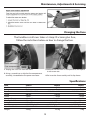
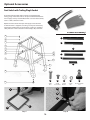
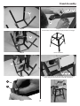
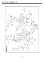
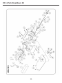
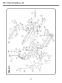
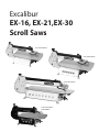
Excalibur EX-16, EX-21,EX-30 Scroll Saws Code 505079 (EX-16) Code 505078 (EX-21) Code 505077 (EX-30) Code 505055 (EX-21) Limited Edition Index of Contents Page Index of Contents 02 Introduction/Warranty02 Rules For Safe Operation 03 Safety Instructions 04 Electrical Requirements 05 Identification of Main Parts & Components 06 Unpacking & Set Up 07 Installation & Assembly 07-08 Choosing & Installing a Saw Blade 08-09-10 Operating Instructions 10-11-12-13 Maintenance, Adjustments & Servicing 14-15 Changing the Fuse 15 Specifications15 Optional Accessories 16 Stand Assembly 17 EX-16 Parts Breakdown/List (A,B) 18-19-20-21 EX-21 Parts Breakdown/List (A,B) 22-23-24-25 EX-30 Parts Breakdown/List (A.B) 26-27-28-29 EX-16, EX-21, EX-30 Drive Assembly Breakdown/List (C) 30-31 Wiring Diagram 32 Notes33-34-35 Introduction/Warranty WARRANTY All component parts of Excalibur by Axminster Tool Centre are carefully tested and inspected during all stages of production, and each unit is thoroughly inspected upon completion of assembly. Because of our commitment to quality and customer satisfaction, Axminster Tool Centre agrees to repair or replace, within a period of 2 years from date of purchase, any genuine part or parts which, upon examination, prove to be defective in workmanship or material. In order to obtain this warranty, all defective parts must be returned freight pre-paid to Axminster Tool Centre. Repairs attempted without our written authorization will void this warranty. Disclaimer: The information and specifications in this manual pertain to the unit as it was supplied from the factory at the time of printing. Because we are committed to making constant Improvements, Axminster Tool Centre reserves the right to make changes to components, parts or features of this unit as deemed necessary, without prior notice and without obligation to install any such changes on previously delivered units. Reasonable care is taken at the factory to ensure that the specifications and information in this manual corresponds with that of the unit with which it was supplied. However, special orders and “after factory” modifications may render some or all information in this manual inapplicable to your unit. Further, as several generations of this scroll saw and several versions of this manual may be in circulation, if you own an earlier or later version of this unit, this manual may not depict your unit exactly. If you have any doubts or questions contact your retailer or our support line with the model and serial number of your unit for clarification. The symbols below advise that you follow the correct safety procedures when Warning using this machine. Fully read manual and safety instructions before use Ear protection should be worn Eye protection should be worn 2 Dust mask should be worn Keep hands away from moving parts and cutting area Rules for Safe Operation To help ensure safe operation, please take a moment to learn the machine’s applications and limitations, as well as potential hazards. Axminster Tool Centre disclaims any real or implied warranty and holds itself harmless for any injury that may result from the improper use of its equipment. 1. Be sure to read, understand and follow all safety warnings and instructions in the supplied Operator’s Manual. 12. Avoid working from awkward or off balance positions. Do not overreach while cutting; keep both feet on floor. Never lean over or reach behind the blade and never pull the work piece through the cut from behind. 2. Do not operate the saw when tired, distracted, or under the effects of drugs, alcohol or any medication that impairs reflexes or alertness. Stay alert! Give your work your undivided attention. 13. Never stand or lean on the saw. Serious injury could occur if the unit is tipped over or if the blade is unintentionally contacted. 3. Keep the work area well lit, clean and free of debris. Cluttered areas and benches invite injuries. 14. Use of parts and accessories NOT recommended by Axminster Tool Centre may result in equipment malfunction or risk of injury. 4. Keep children and shop visitors at a safe distance while operating the saw; do not permit them to operate the scroll saw. 15. Never leave the machine unattended while running or with the power “ON”. 5. Childproof and tamper proof your shop and all machinery with locks, master electrical switches and switch keys, to prevent unauthorised or unsupervised use. Fine particulate dust is a carcinogen that can be hazardous to health. Work in a well ventilated area and use a dust collector whenever possible. 16. Always turn off and disconnect from power source before servicing or changing accessories, blades, bits, and cutters, or before performing any maintenance or adjustments. 17. Make sure that switch is in the “OFF” position before plugging in the power cord. Do not use the saw if the power switch is defected, have defective switches replaced by an authorized service centre. 7. Wear approved safety glasses, dust mask and nonskid footwear. Do not wear loose clothing, gloves, bracelets, necklaces or jewellery while operating the saw. Keep long hair contained by wearing protective hair covering. 18. Make sure saw is properly grounded. If equipped with a three prong plug it should be used with a three-pole receptacle. Never remove the third prong. Avoid body contact with grounded surfaces (e.g. pipes, radiators, stoves, refrigerators). 8. Be sure all adjustment tools, wrenches or other clutter are removed from the machine and/or the table surface before operation. When not in use, tools should be locked-up in a dry place, out of children’s reach and away from flammable substances. 19. Repairs to the saw should only be carried out by qualified people using original spare parts. A guard or other damaged part should be properly repaired or replaced by an authorized service centre. 9. Keep hands well away from saw blade and all moving parts. Use a brush, not hands, to clear away chips and sawdust. 10. Be sure that the saw blade is properly installed, and in the correct cutting direction, before operation. Always use a clean, properly sharpened blade. Dirty or dull blades are unsafe and can lead to accidents. Also, be sure the blade has gained full operating speed before beginning to cut. 20. Inspect power cords and extension wires periodically. If damaged, have them repaired by an authorized service facility. Never yank cords and wires and keep away from heat, oil, and sharp edges. 21. This tool is for indoor use only. Do not expose to rain or use in wet or damp locations. 11. Do not push or force wood into the blade. The saw will perform better and more safely when working at the rate for which it was designed. Do not use for purposes not intended. 3 Safety Instructions 4 Electrical Requirements a a 5 Identification of Main Parts & Components c EX-30 a b q d n e m f g h i o k l EX-16-EX-21 p a b c d e f g h i j k l m n o p q 6 a j b Unpacking & Set Up Installation & Assembly 7 Installation & Assembly Saw guard assembly d d c a b c b Slot the guard clamping arm (d) through the pre-drilled hole in the hexagon clamp (c). Insert the hexagon clamp (c) into the brackets hexagon recess, place the washer (b) over the hexagon clamp thread and secure using the butterfly clamping knob (a). d Saw guard assembly (d) assembled NOTE: DO NOT OVERTIGHTEN otherwise you may strip the thread It is strongly recommended that you mount the machine to a workbench or to a purpose built stand, a pad between the scroll saw and the workbench/stand is also recommended to reduce vibration. a b c Drill four 8mm holes in your workbench/stand and secure using nuts bolts washers (Not Included). e d a f g Choosing & Installing a Saw Blade 8 Choosing & Installing a Saw Blade 9 Choosing & Installing a Saw Blade ! b 2 1 1 c a d a c b 2 d b a a b Operating Instructions 10 a b Operating Instructions a c a b c b Adjusting the Osolation (Front to Back) Top & Bottom Blade holder Alignment a b Fig A Fig B Fig A Fig B Fig C Fig D Fig C Fig D Place a 90˚ square upagainst the blade, the blade movement If the blade is out of alignment please follow the procedures below for can be set between course and fine for different cutting tasks, adjusting the top and bottom blade holders: this can be adjusted by rotating the motor within its’ mounts. Loosen the motor mounting cap head bolts, see figs A enough Place a 90˚ square upagainst the blade, see fig A. Using a 4mm Hex key (a) adjust the grub screw and butterfly nut (b), see fig to be able to rotate the motor (this can be quite stiff to turn), B, until the blade is parallel with the square. (See figs C and D). start the machine and run at approximately 1/4 speed. By rotating the motor, see fig B and carefully observing the blade you will be able to see the blade changing its setting. The finest setting is where the blade moves vertically with the least amount of movement, see fig C backward and forwards horizontally. This should also be where the machine vibrates the least. When you have the setting where you wish it to be, tighten the motor mounting bolts. 11 Operating Instructions 12 Operating Instructions a c b a c b e e d f a d f 13 Maintenance, Adjustments & Servicing b a a 14 b Maintenance, Adjustments & Servicing Changing the Fuse The Excalibur scroll saws takes a 5 Amp 20 x 5mm glass fuse, follow the instrctions below on how to change the fuse. Power connector Fuse compartment 1. Unplug the scroll saw from the mains 2. Using a screwdriver un-clip the fuse compartment assembly, situated below the power connector 3. Remove the fuse from it’s compartment and replace it with a new one 4. Re-insert the fuse assembly until it clips home Specifications Code505079 505078 505077 ModelEX-16 EX-21 EX-30 RatingTrade Trade Trade Power 230V 50Hz 320W 230V 50Hz 320W 230V 50Hz 320W Throat 406mm 535mm 762mm Stroke 18mm 18mm 18mm Cuts per Minute 400 -1,400 400 -1,550 400-1,550 Max Depth of Cut 51mm 51mm 51mm Table Size 305 x 470mm 345 x 597mm 358 x 825mm Arm Tilt Left 35° Right -45° Left 35° Right -45° Left 35° Right -45° Overall L x W x H 686 x 380 x 432mm 812 x 380 x 387mm 1,100 x 394 x 387mm Weight24.5kg 29.5kg 52kg 15 Optional Accessories Foot Switch with Trailing Plug & Socket These two foot-operated safety switches are equipped with trailing plugs and sockets and can easily be inserted between the mains supply and any machine fitted with a no volt release switch, such as a drill, bandsaw or lathe. Operation of the switch interrupts the supply to the solenoid and the machine is stopped; re-starting can only be achieved by operating the NVR switch on the machine, creating an excellent safety measure in those situations where safety is of paramount. Stand Assembly A 1 B 1 2 2 3 3 C C 4 4 B 5 5 E 6 6 D D A E B C D x4 M8 Bolts x24 M8 Coatch Bolts x32 M8 Washers x28 M8 Nuts x4 Thread Rubber Foot E 3 B C 1 2 Step 1 Step 2 16 Stand Assembly E B C 3 6 Step 3 Step 7 Use the holes in the bracket (6) to adjust the the stand height 4 Step 4 Stand assembled 5 A Step 5 C Lower the scroll saw on top of the stand and lineup the holes, secure using the four bolts (A) washers (B) and Nuts (C) 6 D Step 6 B 17 EX-16 Parts Breakdown (A) 18 EX-16 Parts List (A) Part No Description EX16-A04 ALLEN SCREW Specification Qty Part No Description #10-32X1/4” 4 EX16-A50 WARNING LABEL Specification Qty 1 EX16-A05 SWITCH COVER 1 EX16-A51 NYLON NUT #10-32 4 EX16-A06 SWITCH 1 EX16-A52 NYLON NUT 1/4-20UNC 2 EX16-A12 AIR NOZZLE EX16-A18 BOLT 1/4-20 X 1/2” 1 EX16-A53 LOCK WASHER 1/4” 1 2 EX16-A54 FLAT WASHER 1/4” (O.D.I 3) 1 EX16-A19 UPPER & LOWER TENSION PLATE 1 EX16-A55 LABEL EX16-A20 HOLD DOWN MOUNT PLATE 1 EX16-A56 SCREW EX16-A21 ALLEN SCREW EX16-A22 HOLD DOWN CLAMP KNOB EX16-A23 WASHER EX16-A24 HOLD DOWN CLAMP SCREW EX16-A25 HOLD DOWN BAR EX16-A26 CAP SCREW #10-32X3/8” 1/4X16X1.8” #10-32X1/2” 2 EX16-A58 KNOB 1 EX16-A59 NUT EX16-A60 ADJUSTING LEVER 1 CONTROL BOX 1 1 EX16-A62 CROSS BLOCK RETAINER 1 1 EX16-A63 HOUSING CROSS BLOCK 1 HOLD DOWN FORKS 1 EX16-A64 FLAT WASHER 1 EX16-A65 NYLON NUT EX16-A29 TAP SCREW EX16-A30 VR KNOB VR SCREW EX16-A34 MOTOR CONTROL SET EX16-A35 ALLEN SCREW M4X8 1/4-20X1/2” 1 EX16-A61 DUST BLOWER EX16-A31 1 M6 4 EX16-A27 EX16-A33 2 1 EX16-A28 #8-32UNF 3/8” 2 1/4X2-1/2” M6X 16X2 1 M6 1 4 EX16-A66 ALLEN SCREW 1 1 EX16-A67 R FASTENER 1 1 EX16-A68 WASHER 1 4 EX16-A69 NYLON NUT 1 1 EX16-A70 ALLEN SCREW 7 3 EX16-A71 BUTTON 1 EX16-A37 LINE CORD SOCKET 1 EX16-A72 SET SCREW 1 EX16-A38 FUSE 1 EX16-A73 GROUND PLATE 1 EX16-A39 STRAIN RELIEF 1 EX16-A74 GROUND LABEL 1 EX16-A40 GEAR COVER 1 EX16-A77 LABEL 1 EX16-A41 NUT EX16-A45 ALLEN SCREW EX16-A46 SCREW EX16-A47 WASHER EX16-A48 SCREW EX16-A49 MOTOR LABEL 3/8 X T5.5 1 EX16-A78 MAIN BODY 1 #10-32X2-1/4” 4 EX16-A79 TOP COVER 1 3/8”X 5/8” 1 EX16-A80 UPPER ARM 1 #8 5 EX16-A81 CONTROL CABLE 1 #8-32X1/4” 5 EX16-A82 UPPER BLADE GUARD 1 1 EX16-A83 LOWER BLADE GUARD 1 19 EX-16 Parts Breakdown (B) 20 EX-16 Parts List (B) Part No Description EX16-B01 TRUNNION Specification Qty 2 EX16-B03 REAR TRUNNION PLATE 1 EX16-B04 FRONT TRUNNION PLATE 1 EX16-B06 GROUND JUMPER EX16-B07 POWER CORD 1 CSA 1 EX16-B08 SPONG BLOCK 1 EX16-B09 POLYFOAM 1 EX16-B10 SCREW 1/4-20UNCX 1/2 1 EX16-B11 LOCK WASHER 1-Apr 3 EX16-B12 WASHER 1-Apr EX16-B13 BLADE TILT WASHER EX16-B14 BLADE TILT DRIVE GEAR EX16-B15 SCREW 9 2 2 1/4-20UNCX 3/4 10 EX16-B16 ANGLE FOLLOWER EX16-B17 SCREW 2 EX16-B18 WASHER #10X 12X1 8 EX16-B19 NUT 1/4-20UNC 12 #10-32X5/16 8 EX16-B20 ANGLE INDICATOR EX16-B21 ALLEN SCREW EX16-B22 E RING EX16-B23 TILT DETENT BARREL 1 EX16-B24 SPRING 1 EX16-B25 DETENT PLUNGER 1 EX16-B26 TILT HANDLE EX16-B27 WASHER EX16-B28 BLADE TILT LOCKING LEVER EX16-B29 FLAT HEAD SCREW EX16-B38 POINTER EX16-B39 ROUND HEAD SCREW EX16-B40 WASHER EX16-B41 SIDE PANEL EX16-B42 TABLE EX16-B43 WASHER EX16-B44 ALLEN SCREW EX16-B45 TILT LOCK DRAW ROD 1 1/4-20 X 1” ETW-3 2 1 1 1/4X 16X3 1 1/4-20X3/4 4 1 1 M4 X 6MM M4 1 1 2 1 1/4. 1/4-20UNCX 3/4 8 8 1 EX16-B46 COVER 1 EX16-B47 DUST CHUT 1 EX16-B48 ROUND HEAD SCREW EX16-B49 WASHER 21 #8-32unc-5/16 4 #8-32unc 4 EX-21 Parts Breakdown (A) 22 EX-21 Parts List (A) Part No Description EX21-A01 MAIN BODY EX21-A03N TOP COVER EX21-A04 ALLEN SCREW EX21-A05 EX21-A06 EX21-A12 AIR NOZZLE EX21-A18 BOLT EX21-A19 EX21-A20 EX21-A21 ALLEN SCREW EX21-A22 HOLD DOWN CLAMP KNOB EX21-A23 WASHER EX21-A24 HOLD DOWN CLAMP SCREW EX21-A25 HOLD DOWN BAR EX21-A26 CAP SCREW EX21-A27 EX21-A28 EX21-A29 TAP SCREW EX21-A30 VR KNOB EX21-A31 EX21-A32 EX21-A33 SCREW EX21-A35 ALLEN SCREW EX21-A37 LINE CORD SOCKET EX21-A38 FUSE EX21-A40 GEAR COVER EX21-A41 NUT EX21-A45 ALLEN SCREW EX21-A46 SCREW EX21-A47 WASHER EX21-A48 SCREW Specification Part No Description 1 EX21-A49 MOTOR LABEL 1 EX21-A50 WARNING LABEL 4 EX11-A51 NYLON NUT #10-32 4 SWITCH COVER 1 EX21-A52 NYLON NUT 1/4-20UNC 2 SWITCH 1 EX21-A53 LOCK WASHER 1/4” 1 1 EX21-A54 FLAT WASHER 1/4”(O.D.13) 1 2 EX21-A55 LABEL UPPER & LOWER TENSION PLATE 1 EX21-A56 SCREW HOLD DOWN MOUNT PLATE 1 EX21-A57 UPPER ARM 2 EX21-A58 KNOB 1 EX21-A59 NUT 4 EX21-A60 ADJUSTING LEVER 1 1 EX21-A61 CONTROL BOX 1 1 EX21-A62 CROSS BLOCK RETAINER 1 1 EX21-A63 HOUSING CROSS BLOCK 1 HOLD DOWN FORKS 1 EX21-A64 FLAT WASHER DUST BLOWER 1 EX21-A65 NYLON NUT 4 EX21-A66 ALLEN SCREW 1 1 EX21-A67 R FASTENER 1 VR 1 EX21-A68 WASHER 1 CONTROL CABLE 1 EX21-A69 NYLON NUT 1 M4X8 4 EX21-A70 ALLEN SCREW 7 1/4-20 X 1/2” 3 EX21-A71 BUTTON 1 1 EX21-A72 SET SCREW 1 1 EX21-A73 GROUND PLATE 1 #10-32X 1/4” 1/4-20 X 1/2” #10-32X3/8” 1/4X16X1.8” #10-32X 1/2” #M2UNF 3/8” 5AMP Qty Specification Qty 1 1 2 1/4X2-1/2” 2 1 1 M6 1 M6X 16X2 1 M6 1 1 EX21-A74 GROUND LABEL 1 3/8 X T5.5 1 EX21-A75 STRAIN RELIEF 1 #10-32X2-1/4” 4 EX21-A76 MOTOR CONTROL SET 1 3/8”X 5/8” 1 EX21-A77 LABEL 1 #8 5 EX21-A82 UPPER BLADE GUARD 1 #8-32 X 1/4” 5 EX21-A83 LOWER BLADE GUARD 1 23 EX-21 Parts Breakdown (B) 24 EX-21 Parts List (B) Part No Description Specification Qty EX21-B01 TRUNNION 2 EX21-B02 SIDE PANEL 2 EX21-B03 REAR TRUNNION PLATE 1 EX21-B04 FRONT TRUNNION PLATE 1 EX21-B05 TABLE 1 EX21-B06 GROUND JUMPER EX21-B07 POWER CORD EX21-B08 SPONG BLOCK 1 EX21-B09 POLYFOAM 1 EX21-B10 SCREW 1/4-20UNCX1/2 1 EX21-B11 LOCK WASHER 1-Apr 3 EX21-B12 WASHER 1-Apr 9 EX21-B13 BLADE TILT WASHER EX21-B14 BLADE TILT DRIVE GEAR EX21-B15 SCREW EX21-B16 ANGLE FOLLOWER EX21-B17 SCREW EX21-B18 WASHER #10X 12X 1 8 EX21-B19 NUT 1/4-20UNC 12 EX21-B20 ANGLE INDICATOR EX21-B21 ALLEN SCREW EX21-B22 E RING EX21-B23 TILT DETENT BARREL 1 EX21-B24 SPRING 1 EX21-B25 DETENT PLUNGER 1 EX21-B26 TILT HANDLE EX21-B27 WASHER EX21-B28 BLADE TILT LOCKING LEVER EX21-B29 FLAT HEAD SCREW EX21-B36 TILT LOCK DRAW ROD 1 EX21-B38 POINTER 1 EX21-B39 ROUND HEAD SCREW EX21-B40 WASHER EX21-B46 COVER EX21-B47 DUST CHUT EX21-B48 ROUND HEAD SCREW EX21-B49 WASHER 1 CSA 1 2 2 1/4-20UNCX3/4 10 2 #10-32X5/16 8 1 1/4-20 X 1” 2 ETW-3 1 1 1/4X16X3 1 1 12/6/201312/6/2013 4 M4 X 6MM 1 M4 1 1 1 25 #8-32unc-5/16 4 #8-32unc 4 EX-30 Parts Breakdown (A) 26 EX-30 Parts List (A) Part No Description Specification Qty EX30-A01 MAIN BODY EX30-A03 TOP COVER EX30-A04 ALLEN SCREW EX30-A05 SWITCH COVER 1 EX30-A53 LOCK WASHER 1/4” 1 EX30-A06 SWITCH 1 EX30-A54 FLAT WASHER 1/4” (O.D.I 3) 1 EX30-A12 AIR NOZZLE 1 EX30-A55 LABEL EX30-A20 HOLD DOWN MOUNT PLATE 1 EX30-A56 SCREW EX30-A21 ALLEN SCREW EX30-A22 HOLD DOWN CLAMP KNOB EX30-A23 WASHER EX30-A24 HOLD DOWN CLAMP SCREW EX30-A25 HOLD DOWN BAR EX30-A26 CAP SCREW EX30-A27 EX30-A28 EX30-A29 TAP SCREW EX30-A30 VR KNOB EX30-A31 EX30-A32 #10-32 X 1/4” #10-32X3/8” Description Specification Qty 1 EX30-A50 WARNING LABEL 1 EX30-A51 NYLON NUT #10-32 4 4 EX30-A52 NYLON NUT 1/4-20UNC 2 1 2 1/4X2-1/2” 2 2 EX30-A57 UPPER ARM 1 1 EX30-A58 KNOB 1 4 EX30-A59 NUT 1 EX30-A60 ADJUSTING LEVER 1 1 EX30-A61 CONTROL BOX 1 1 EX30-A62 CROSS BLOCK RETAINER 1 HOLD DOWN FORKS 1 EX30-A63 HOUSING CROSS BLOCK DUST BLOWER 1 EX30-A64 FLAT WASHER 4 EX30-A65 NYLON NUT 1 EX30-A66 ALLEN SCREW 1 VR 1 EX30-A67 R FASTENER 1 CONTROL CABLE 1 EX30-A68 WASHER 1 M4X8 4 EX30-A69 NYLON NUT 1 1/4-20X1/2” 3 EX30-A70 ALLEN SCREW 7 EX30-A33 SCREW EX30-A35 ALLEN SCREW 1/4X16X1.8” Part No #10-32X 1/2” #8-32UNF 3/8” M6 1 1 M6X16X2 1 M6 1 EX30-A37 LINE CORD SOCKET 1 EX30-A71 BUTTON 1 EX30-A38 FUSE 1 EX30-A72 SET SCREW 1 EX30-A40 GEAR COVER EX30-A41 NUT EX30-A45 ALLEN SCREW EX30-A46 SCREW EX30-A47 WASHER EX30-A48 SCREW EX30-A49 MOTOR LABEL 1 EX30-A73 GROUND PLATE 1 3/8 X T5.5 1 EX30-A74 GROUND LABEL 1 #10-32X2-1/4” 4 EX30-A75 STRAIN RELIEF 1 3/8”X 5/8” 1 EX30-A76 MOTOR CONTROL SET 1 #8 5 EX30-A77 LABEL 1 #8-32 X 1/4” 5 EX30-A82 UPPER BLADE GUARD 1 1 EX30-A83 LOWER BLADE GUARD 1 27 EX-30 Parts Breakdown (B) 28 EX-30 Parts List (B) Part No Description Specification Qty EX30-B01 TRUNNION 2 EX30-B02 SIDE PANEL 2 EX30-B03 REAR TRUNNION PLATE 1 EX30-B04 FRONT TRUNNION PLATE 1 EX30-B05 TABLE 1 EX30-B06 GROUND JUMPER EX30-B07 POWER CORD EX30-B08 SPONG BLOCK 1 EX30-B09 POLYFOAM 1 EX30-B10 SCREW 1/4-20UNCX1/2 1 EX30-B11 LOCK WASHER 1-Apr 3 EX30-B12 WASHER 1-Apr 9 EX30-B13 BLADE TILT WASHER EX30-B14 BLADE TILT DRIVE GEAR EX30-B15 SCREW EX30-B16 ANGLE FOLLOWER EX30-B17 SCREW EX30-B18 WASHER EX30-B19 NUT EX30-B20 ANGLE INDICATOR EX30-B21 ALLEN SCREW 1 CSA 1 2 2 1/4-20UNCX3/4 10 2 #10-32X5/16 8 #10X12X1 8 1/4-20UNC 12 1 1/4-20 X 1” 2 ETW-3 1 EX30-B22 ERING EX30-B23 TILT DETENT BARREL 1 EX30-B24 SPRING 1 EX30-B25 DETENT PLUNGER 1 EX30-B26 TILT HANDLE EX30-B27 WASHER EX30-B28 BLADE TILT LOCKING LEVER EX30-B29 FLAT HEAD SCREW EX30-B36 TILT LOCK DRAW ROD 1 EX30-B38 POINTER 1 EX30-B39 ROUND HEAD SCREW EX30-B40 WASHER EX30-B46 COVER 1 EX30-B47 DUST CHUT 1 EX30-B48 ROUND HEAD SCREW EX30-B49 WASHER 1 1/4X16X3 1 1 1/4-20X3/4 29 4 M4 X 6MM 1 M4 1 #8-32unc-5/16 4 #8-32unc 4 EX-16, EX-21 EX-30 Drive Assembly Breakdown/List (C) 30 EX-16, EX-21 EX-30 Drive Assembly Breakdown/List (C) Part No Description 2 EX21-C02 BALANCE BLOCK 3 EX21-C03 SET SCREW 4 EX21-C04 ALLEN SCREW 5 EX21-C05 6 EX21-C06 7 EX21-C07 MOTOR COVER PLATE 8 EX21-C08 SCREW M6X16 9 EX21-C09 BEARING 608ZZ 10 EX21.C10 MOTOR CAM 11 EX21-C11 NUT Qty Part No Description 1 37 EX21-C37 SET SCREW Specification Qty M6X8 2 M6X6 1 38 EX21-C38 BLADE CLAMP THUMB SCREW 2 1/4-20X1/2 3 39 EX21-C39 BLADE 1 LOCK WASHER 1/4 3 40 EX21-C40 ALLEN KEY FLAT WASHER 1/4X16X1.8 3 41C EX21-C41C CLAMP BRACKET 1 42 EX21-C42 SET SCREW 4 43 EX21-C43 SPRING 1 44 EX21-C44 TENSION LEVER (FOR EX-16 & EX-21) 5MM 1 12 EX21-C12 BEARING 14C EX21-C14C ROCKER CAM 15 EX21-C15 LOCK NUT 17 EX21-C17 BEARING 18C EX21-C18C BEARING INNER SLEEVE (SHORT) 19 EX21-C19 CAP SCREW 20N EX21-C20N BEARING COVER 21 EX21-C21 BEARING 22 EX21-C22 MAIN ROCKER PIVOT 23 EX21-C23 NUT 24 EX21-C24 CAP SCREW 26 EX21-C26 AIR PUMP BELLOWS 27 Specification 1 M8XP1.25LH 810 1 M5 1 7MM 1 SCREW POST 5X18 1 46 EX21-C46 SLIDING BRACKET 1 46A EX21-C46A UPPER BLADE TENSION ASSEMBLY (FOR EX-16 & EX-21) 1 EX30-C46A UPPER BLADE TENSION ASSEMBLY (FOR EX-30) 1 57 EX21-C57 WASHER M4X10X1 4 2 58C EX21-C58C INNER BEARING SLEEVE (LONG) 06.02 X 16.50MM 4 59C EX21-C59C BEARING INNER SLEEVE 08.03X21.50MM 1 60 EX21-C60 WASHER 61 EX21-C61 CAP SCREW 62 EX21-C62 WASHER 64 EX16-C64 DRIVE LINK ASS’Y (LONG) 2 EX21-C64 DRIVE LINK ASS’Y (LONG) 2 EX30-C64 DRIVE LINK ASS’Y (LONG) 2 1412 2 014.04X35.5MM 1 M4 12 M4X25 2 2 M5 2 M4X27 2 M4X14X 1 12 M8 X 15 X 0.6 6 EX16C64A LINKAGE ASSEMBLY 1 08.03 X18.40MM 2 EX21-C64A LINKAGE ASSEMBLY 1 06.03 X 37MM 2 EX30-C64A LINKAGE ASSEMBLY 1 65 EX21-C65 MOTOR 1 66 EX21-C66 SPACER 67 EX21-C67 BEARING INNER SLEEVE (SHORT) 68 EX21-C68 CAP SCREW 69 EX21-C69 WASHER 70 EX21-70 CARBON BRUSH 30C EX21-C30C BEARING INNER SLEEVE (LONG) 31C EX21-C31C ROCKER MOUNT 32C EX21-C32C CAP SCREW M4X45 2 33C EX21-C33C CAP SCREW M4X25 4 35 EX21-C35 STRUT 2 36C EX21-C36C BLADE CHUCK 1 36ASSY EX21C-36ASSY BLADE CHUCK BOTTOM ASSEMBLY TENSION LEVER (FOR EX-30) EX21-C45 1 1 INNER BEARING SLEEVE - FRONT ROCKER EX30-C44 M5X28 UPPER AND LOWER ROCKER ASSEMBLY WASHER 1 2 EX21-C27C EX21-C29C 1 10 2 EX21-C28 1/4-20UNC 609 FRONT ROCKER 29C 1 06.03X21 MM EX21-C27 28 1 45N 1 3 3MM 2 1 1 06.03 X16MM 2 M4X30 2 M4 X 8 X 1 8 2 IMPORTANT: When ordering replacement parts, always give the model number, serial number of the machine and part number. Also a brief description of each item and quantity desired. 31 Wiring Diagram 32 Notes 33 Notes 34 Notes 35 Please dispose of packaging for the product in a responsible manner. It is suitable for recycling. Help to protect the environment, take the packaging to the local recycling centre and place into the appropriate recycling bin. Only for EU countries Do not dispose of electric tools together with household waste material. In observance of European Directive 2002/96/EC on waste electrical and electronic equipment and itsimplementation in accordance with national law, electric tools that have reached the end of their life must be collected separately and returned to an environmentally compatible recycling facility. Axminster Tool Centre, Unit 10 Weycroft Avenue, Axminster, Devon EX13 5PH axminster.co.uk