1
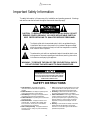
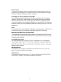
AUDIOACCESS
ii
Table of Contents
Important Safety Information ................................................................................................. iv
Unpacking and Inspection ...................................................................................................... vi
About This Manual ................................................................................................................. 1
PX-600 Software ..................................................................................................................... 1
KPS Software ........................................................................................................................... 1
PX-603 Product Description ................................................................................................... 2
Technical Specifications ........................................................................................................... 3
Front Panel .............................................................................................................................. 4
Rear Panel ............................................................................................................................... 5
System Operation .................................................................................................................... 6
Keypad Control ................................................................................................................. 6
System Installation .................................................................................................................. 8
Pre-wire ............................................................................................................................. 8
Keypad Installation ............................................................................................................ 8
Final Hookup .................................................................................................................. 10
PX-603 Programming ...................................................................................................... 13
Zone Setup ...................................................................................................................... 14
Group Setup .................................................................................................................... 14
Paging Setup .................................................................................................................... 15
Multi PX-600 Systems ..................................................................................................... 15
Setting Turn on Volume ................................................................................................... 15
Appendix I:
System Design ....................................................................................................... 16
System 1 Block Diagram .................................................................................................. 17
System 1 Line Diagram .................................................................................................... 19
System 2 Block Diagram .................................................................................................. 19
System 2 Line Diagram .................................................................................................... 21
Appendix II:
Dealer/Manufacturer Questions and Answers ....................................................... 22
Appendix III: Troubleshooting
Guide ........................................................................................ 24
Audioaccess
2081 South Main Street
Middletown, CT 06457
Manufactured in USA
A Harman International Company
©1995 Audioaccess
iii
AUDIOACCESS
Important Safety Information
The safety information in this summary is for installation and operating personnel. Warnings
and cautions can also be found throughout the manual where they apply.
CAUTION
RISK OF ELECTRIC SHOCK
DO NOT OPEN
CAUTION: TO REDUCE THE RISK OF ELECTRICAL SHOCK, DO NOT
REMOVE COVER (OR BACK). NO USER SERVICEABLE PARTS INSIDE. REFER SERVICING TO QUALIFIED SERVICE PERSONNEL
The lightning flash with the arrowhead symbol, within an equilateral triangle,
is intended to alert the user to the presence of un-insulated "dangerous voltage"
within the product's enclosure that may be of sufficient magnitude to constitute
a risk of electric shock to persons.
The exclamation point within an equilateral triangle is intended to alert the user
to the presence of important operating and maintenance (servicing) instructions
in the literature accompanying the appliance.
WARNING: TO REDUCE THE RISK OF FIRE OR ELECTRICAL SHOCK,
DO NOT EXPOSE THIS APPLIANCE TO RAIN OR MOISTURE.
TO PREVENT ELECTRICAL SHOCK DO NOT USE
THIS PLUG WITH AN EXTENSION CORD, RECEPTACLE OR OTHER OUTLET WITHOUT PROPER
GROUNDING CONNECTION.
SAFETY INSTRUCTIONS
1. Read Instructions - All the safety and operating
instructions should be read before the appliance is
operated.
2. Retain Instructions - The safety and operating instructions should be retained for future reference.
3. Heed Warnings - All warnings on the appliance and in
the operating instructions should be adhered to.
4. Follow Instructions - All operating and use instructions
should be followed.
5. Water and Moisture - The appliance should not be
used near water - for example, near a bathtub, washbowl, kitchen sink, laundry tub, in a wet basement,
near a swimming pool, and the like.
6. Wall or Ceiling Mounting - The appliance should be
mounted to a wall or ceiling only as recommended by
the manufacturer.
iv
7. Heat - The appliance should be situated away from heat
sources such as radiators, heat registers, stoves, or other
appliances (including amplifiers) that produce heat.
8. Grounding - Precautions should be taken so that the
grounding means of the appliance is not defeated.
9. Power Cord Protection - Power supply cords should be
routed so that they are not likely to be walked on or
pinched by items placed upon or against them, paying
particular attention to cords and plugs, convenience
receptacles, and the point where they exit from the
appliance.
10. Servicing - The user should not attempt to service the
appliance beyond that described in the operating
instructions. All other servicing should be referred to
qualified service personnel.
Power Source
This product is intended to operate from a power source that does not apply more than the
specified volts RMS indicated on the rear panel of the unit, as referenced between the supply
conductors or between either supply conductor and ground.
Grounding the PX-603 Multi-Room Expander
This product is grounded through the ground conductor of the power cord. To avoid the
potential of electrical shock, plug the power cord into a properly wired and grounded receptacle before operating the PX-603. A protective ground connection, by way of the ground
conductor in the power cord, is essential for safe operation. A standard 3-pin IEC type in good
operational condition is the only acceptable cord that may be used to connect the PX-603 to a
power source.
Fuses
To avoid potential fire, electrical hazard and damage to internal components, replace fuses only
with fuses of the correct type, voltage and current rating as specified in this manual.
Removal of PX-603 Cover and Front Panel
To avoid personal injury and to ensure proper operation, do not remove the PX-603 cover or
front panel except as directed within this manual. Do not operate the unit without the covers
and panels properly installed.
Operating Environment
For the best operating results, install the PX-603 in an area where it will not be exposed to
direct sunlight or any heat source. The unit should be operated in a temperature range from
40˚ to 95˚F (5˚ to 35˚C). Place the unit where there is sufficient air circulation. It generates
heat and must be ventilated.
PX-600 Software
The PX-603 will only operate in PX-600 systems with software version 2.0 or above. See
page 1 of this manual for additional information.
KPS Software
KPS keypads must have software version 1.6 or above to operate correctly with the PX-600/
PX-603 system. See page 1 of this manual for additional information.
v
AUDIOACCESS
Unpacking and Inspection
Use caution when unpacking this product and follow these procedures:
• Inspect the shipping carton(s) for exterior damage before opening them.
If any damage is discovered, notify your freight agent and Audioaccess immediately.
• To open the shipping box, carefully cut through the packaging tape along the top edges and
middle of the box, taking care not to cut through surrounding cardboard. Carefully remove
the staples securing the top flaps.
• Inspect the PX-603 Multi-Room Expander for signs of damage.
• Verify that the following items are contained in the package:
❏ PX-603 Multi-Room Expander
❏ IEC AC power cord (120 volt version only)
❏ Important Safeguards sheet
❏ Limited Warranty sheet (USA and Canada only)
❏ Limited Warranty Registration card (USA and Canada only)
❏ PX-603 Installation Manual
❏ PX-603 Owner’s Manual
Important Note
Save all packing material. It is essential should the unit ever need to be returned for repair.
vi
About This Manual
This manual contains information regarding the functions and installation of the Audioaccess
PX-603 Multi-Room Expander in new and existing PX-600 systems. Within it are revised
PX-600 programming instructions and updated KPS switch-setting data that augment the
material in the PX-600 Installation Manual. However, this manual does not contain the
essential instructions covered in the PX-600 Installation Manual.
Before you finalize your system design and begin installation, we suggest you review two
appendices of this manual. The Question and Answer appendix (Appendix II) contains actual
questions frequently asked by Audioaccess system designers and installers in conversations with
our Technical Support Department and during dealer training sessions. The straight-forward,
forum style explanations will help you better understand the interaction of the PX-600 and
PX-603 and help you make design choices early-on in system planning that will allow you to
configure a system that exactly matches your client’s needs. Furthermore, the System Design
Appendix (Appendix I) contains real-life descriptions of PX-603 applications, as well as representative block and wiring diagrams.
We recommend that even experienced Audioaccess installers and system designers consider the
PX-600 and PX-603 Installation Manuals an essential part of their tool kit. For a complete
Audioaccess Technical Resource Manual which includes installation manuals, tech notes and
tech bulletins, please call our Customer and Technical Support Department at 860-346-0896.
PX-600 Software
To make existing PX-600 systems PX-603 compatible, you will need to upgrade the PX-600
software version to v. 2.0 or later. Earlier PX-600 software versions do not include the programming screens for PX-603 setup. To determine the PX-600 software version, plug in the
PX-600 Programmer, press the PGM button, highlight ABOUT PX-600, and press ENTER.
The software version and date will appear on the programmer screen. All PX-600s shipped
after the release of the PX-603 will have v. 2.0 or later software installed.
KPS Software
To make existing KPS keypads PX-603 compatible, you will need to make sure they are
software version 1.6 or above. Earlier KPS software versions will not operate properly in
PX-600/603 systems. To determine the KPS software version, remove the wallplate surrounding each keypad and look for a pink dot on the mounting bracket. If a pink dot is not present,
or if the dot is another color, remove the keypad from the wall and remove the rear plate. The
software version should be on the processor I.C. itself. All KPS's shipped since July, 1994 have
software version 1.6 or above.
1
AUDIOACCESS
PX-603 Product Description
The PX-603 Multi-Room Expander allows the addition of three areas of independent volume
control to any existing zone or zones of a PX-600 Multi-Room Preamp/Controller system
without the use of autoformers. The chassis contains three line-level audio inputs, three stereo
amplifiers with digitally controlled volume and fixed equalization, and a four conductor
communication bus. Up to six PX-603s may be connected to any PX-600 in a system for a
total of 18 additional areas of independent volume control per PX-600. Each area may be
controlled from the traditional KPS eight-button, wall-mounted keypad or a KP3 three-button
keypad. An Audioaccess handheld IR remote control may be used with either keypad for
on/off, volume and source control for the entire zone through the IR receiver built into both
keypads.
Each PX-603 Audio Input receives a line-level signal from a PX-600 Zone Output. Room
configurations and independent bass equalization (3dB boost) are set via DIP switches on the
PX-603 rear panel. ALL-ON grouping and time-out features are programmed at the PX-600
control unit with a detachable PX-600 Programmer. Turn-on volume for PX-603 rooms is set
at the KPS or KP3 keypad in each room.
General Features
• Simple, intuitive operation, installation and programming
• Zone source selection is available from KPS keypad and IR remote Controls
• KPS keypads and IR remotes control basic functions of the audio sources for the zone
• KP3 keypads control room on/off, volume level and mute
• PX-603 rooms may be activated with zone ALL-ON group
• Paging and doorbell features available with optional Page/Doorbell Module
• Independent access to each of three audio inputs and three stereo amplifiers
• Independent volume control and bass EQ in each room
• Infrared receiver built into KP3 and KPS keypads
• Four-conductor wiring directly from PX-603 and KPSs to KPT (two twisted pairs: telephone
or data cable)
• Six-conductor wiring directly from PX-603 to KP3 keypads
• Attaches to keypad termination board (KPT) for easy pre-wiring/troubleshooting
• Two-way communication with PX-600 Controller via four conductor bus
Inputs
• Three line-level audio inputs
• Three six-conductor modular KP3 keypad inputs
• AC power input
• DIP switch settable room addresses and Bass Boost
2
Outputs
• Loop-thru audio output for each audio input
• Push-terminal speaker connectors for three stereo pairs
• 22 Watts per channel into eight ohm speakers with all channels driven
Technical Specifications
Specification
Room Outputs
Frequency Response
20-20k Hz, +0, -2.4 dB
S/N (ref: 1k Hz at rated output, filter at 30k Hz)
>100 dB
THD + Noise @ 1k Hz, Filter at 30k Hz
<0.01% (@ rated power)
Maximum Output
22W into 8Ω (6 channels driven)
24W into 8Ω (4 channels driven)
28W into 8Ω (2 channels driven)
Left/Right Crosstalk (@ 1k Hz, each input)
<-81 dB
Room to Room Crosstalk (@ 1k Hz, any two rooms)
<-83 dB
Volume Attenuation
0-76dB, 2dB steps
Mute Attenuation
>110 dB
Bass (Baxandall type, 100 Hz)
0dB, + 3dB (selectable)
Input Sensitivity
1.5Vrms for rated output
Connector Type
RCA with short hot pin (makes shield connection first)
Power requirements *
120 volts AC, 60Hz, 480 watts max (230 volts AC, 50Hz, 480 watts max)
Dimensions
17 3/8" W x 4" H x 15 1/2" D (442 mm x 102 mm x 394 mm)
Includes connectors and feet
Weight
19 lbs/ 9 kg
* Refer to rear panel of unit.
3
AUDIOACCESS
Companion Products and Accessories
The PX-603 is a Multi-Room Expander designed specifically to add up to three areas of independent volume control to any zone of an Audioaccess system. The PX-603 complements the
PX-600 Multi-Room Preamp/Controller both functionally and aesthetically, and is visually
identical to the PX-612 Multi-Room Amplifier. The combination PX-600, PX-612 and
PX-603 system is a compact, easy to install, simple to operate, cost-effective solution for all your
multi-room needs. We have included system design and installation information pertaining to
PX-600, PX-612 and PX-603 configurations in this manual. Detailed descriptions and specifications for the PX-600 and PX-612 are contained in their respective installation manuals.
The following accessories are part of the PX-600/603 family of products. These products will
be referred to throughout the manual as they relate to a PX-600/603 installation. For a
complete description of PX-600 accessories, please refer to the PX-600 Installation Manual.
• KPS
Full-function keypad (available in white, ivory or black)
• KP3
Three-button keypad (available in white only)
• RT-A
Dedicated handheld IR remote control
• URC-8090
Programmable handheld IR remote control
• KPT
Keypad Termination Board
• PDM
Page/Doorbell Module
• MCI
Multi-room Computer Interface
Front Panel
PX-603
Multi-Room Expander
Power
1
1
Power Indicator
(LED)
The POWER INDICATOR reflects the current status of the PX-603. It will glow green when
at least one PX-603 room is in use or yellow when in standby.
CAUTION
4
Rear Panel
3
R
ROOM
SYSTEM
ZONE
ROOM
3
ROOM
2
SYSTEM
3
ROOM
2
ZONE
1
1
KPS
KP-3
+
ROOM
L
SYSTEM
R
ROOM
L
L
L
+
BLK
2
R
ZONE
L
YEL
3
GRN
2
480 WATTS
ELECTRIC SHOCK DO NOT EXPOSE THIS EQUIPMENT TO
RAIN OR MOISTURE. DO NOT REMOVE COVER. NO USERSERVICEABLE PARTS INSIDE. REFER SERVICING TO
QUALIFIED SERVICE PERSONNEL.
AVIS: RISQUE DE CHOC ELECTRIQUE - NE PAS OUVRIR
1
1
~ 60Hz
120V
WARNING: TO REDUCE THE RISK OF FIRE OR
CAUTION
RISK OF ELECTRIC SHOCK
DO NOT OPEN
SERIAL NUMBER
RED
MODEL: PX-603
MANUFACTURED IN THE USA
AUDIOACCESS, HAYWARD, CA
1 2 3
R
R
ON
–
1 2 3
–
EQ
AUDIO INPUTS
SPEAKER OUTPUTS
1
2
3
1
4
5
ON
ON
1 2 3 4 5 6 7 8
KEYPADS
1 2 3 4 5 6 7 8
1 2 3 4 5 6 7 8
ROOM CONFIGURATIONS
POWER
6
7
8
Bass EQ
(DIP Settings)
The Bass EQ settings provide 3dB of bass boost independently selectable for each room.
2
Audio Inputs / Loop-Thru
(RCA connectors)
The AUDIO INPUTS have corresponding loop-thru outputs for connecting up to three
PX-603 rooms to the Zone Output of any PX-600 zone without the use of Y-connectors.
3
Speaker Outputs
(Push Terminals)
There is one stereo pair of SPEAKER OUTPUTS for each PX-603 amp. The outputs will
accept up to 12 AWG speaker wire.
4
KP3 Connections
(Six-conductor telephone modular connectors)
KP3 keypads are switches with an IR receiver. The six-conductor wire allows hardwiring and
system IR communication.
5
KPS Connection
(Four conductor pluggable screw terminal)
The KPS connection allows the PX-603 to communicate with PX-600's and KPS Keypads via
a KPT.
6
Room Configurations
(DIP settings)
Each PX-603 room is associated with a zone, room and system via an 8 position DIP switch.
7
Power Switch
The POWER SWITCH turns the main power to the PX-603 on and off.
8
Power Inlet
The POWER INLET allows connection of the PX-603 to AC power via a standard IEC
grounded power cord (included with 120 volt version).
5
AUDIOACCESS
System Operation
The Audioaccess remote KPS and KP3 keypads and handheld IR remotes are an integral part
of a PX-600/PX-603 system. They are, to a large extent, the whole system from your clients’
point of view. For a description of the operation of a PX-600/PX-603 system from a KPS
keypad or IR remote controller, see the PX-600 Installation Manual.
KPS Keypad
RT-A
Handheld IR
Remote Control
KP3 Keypad
URC-8090
Handheld IR
Remote Control
PX-603 rooms share the source active in the PX-600 main room for the zone. When all rooms
in a PX-600 zone are turned off, source selection for the zone defaults to TUNER (unless a
room is still active and using a different source). The PX-600 Zone Output connected to the
PX-603 Audio Input carries a constant, fixed line-level signal that is present as long as the
PX-600 main power is on, whether or not the PX-600 main room is on. When a PX-603
room is turned on and the PX-600 main room is not active, the default source is TUNER.
Keypad Control
ON
• To turn on a single PX-600 or PX-603 room, momentarily press the ON button. The red
ON LED will illuminate on the KPS and KP3 keypads for that room. If the zone is turned
on from other than the main room, the green FM LED will light on KPS keypads in the
zone, but the red LED and main room audio will not come on. The TUNER input is
selected when any zone is first turned on from the PX-600 main room or PX-603 rooms.
• To turn off a single PX-600 or PX-603 room, momentarily press the ON button again.
• To turn on a group of PX-600 zones and selected PX-603 rooms (an ALL-ON group), start
with the room off, then press-and-hold the ON button on any keypad in the ALL-ON
group until the red ON LED flashes on the keypad (about 2 seconds). Note: pressing the
button until the associated LED flashes is called "press-and-hold".
6
• To turn off an ALL-ON group, momentarily press the ON button from any room within
the group.
• To turn off all rooms in the system regardless of ALL-ON grouping, go to any keypad,
make sure it is ON, then press-and-hold the ON button until the red ON LED flashes on
the keypad (about 2 seconds).
VOLUME ▲ ▼
• To increase the volume, press ▲. To decrease the volume, press ▼.
• To mute the audio, press ▲ and ▼ together. (Press the MUTE button on the IR remote
control to get the same response.)
• To un-mute the audio, press either the ▲ or ▼ buttons. (Press MUTE again on the IR
remote.)
• To set PX-603 room turn-on volume: turn the room ON, adjust the volume to desired
level, turn the room off, and within 5 seconds press ▲ and ▼ simultaneously. The LED
will flash to indicate acceptance of the new setting.
Note
For a complete description of KPS and IR remote button functions, refer to the PX-600
Installation Manual.
7
AUDIOACCESS
System Installation
Pre-wire
As in the PX-600 Installation Manual, we strongly suggest home-run wiring for all KPSs
and PX-603s in every system. Although a list of reasons for doing so appears in the PX-600
Installation Manual, several points are worth repeating here:
• Systems will be more easily serviced.
• Trouble-shooting time will be reduced.
• It is much easier to locate a faulty component.
• You and your clients will be happier if you can isolate and correct problems quickly.
During pre-wire, all speaker, KPS/KP3 keypad and other wiring is routed, and gang boxes or
rings are installed for the keypads. General pre-wire and trim-out instructions are covered in
the PX-600 Installation Manual, but there are some specific considerations for installations
that include the PX-603.
The four-conductor bus of each PX-603 should be home-run to a KPT for communication
with the PX-600.
KP3s require six-conductor, 24 AWG wire and must be home-run directly to the PX-603.
KPS keypads that will be used to control PX-603 rooms are not connected to the PX-603.
They should be home-run to a KPT. Distribute KPSs evenly among KPTs to equalize
electrical drain throughout the system, especially in multiple PX-600 systems.
Keypad Installation
This section covers the various aspects of installing, configuring and using the Audioaccess KPS
and KP3 keypads with the PX-603 Multi-Room Expander.
Keypad Termination Board (KPT)
The KPT (sold separately) is used to connect multiple, home-run KPS keypads and PX-603s.
Up to six separate connections may be made to the KPT in addition to a jumper to the
PX-600. The KPT may be mounted in any location between the PX-600, PX-603, and the
keypads. We recommend that it be easily accessible. The KPT is useful when troubleshooting
keypad and PX-603 operations, since individual lines may be tested by unplugging all but the
one in question. Miswires, incorrect DIP switch settings or malfunctioning keypads or
PX-603s can be quickly identified in this manner.
Daisy Chained Wiring
Daisy chaining refers to a method in which you connect a cable from one KPS keypad to the
next, with the final termination made directly to the PX-600 rear panel. This method is often
used when home-runs are not possible. In new construction, the risk of wire damage during
all stages of construction is high, and the daisy chaining method compounds the risk of losing
connection to many keypads with one accident. Thus, while daisy chaining may seem
efficient, extra care must be used when routing the wiring, especially in new construction.
Because KP3 keypad connections are hard-wired, KP3s must be home-run to the PX-603;
they cannot be daisy chained.
8
Home-Run Wiring
Ideally, all KPS and PX-603 wiring should be home-run separately to one or more KPTs, then
to the KEYPAD input on the PX-600 rear panel. This is the safest, most reliable method.
Each KPS and PX-603 should be connected to a separate connector on the KPT. If you
require more than six connections, use another KPT.
Keypad Mounting and Connection
Mount the KPS and KP3 keypads in ordinary electrical boxes or plaster rings. The bezels
of both keypads are sized for a single-gang “Decora®” style wall plate. Use caution when
attaching the wall plates to the keypads, as the paint on the bezels of the keypads can chip.
The KPS wiring color code is shown on the back-plate of each keypad and on the rear panels
of the PX-600 and PX-603. Be certain to follow the wire color code for all connections.
Terminate the cable on the keypad first, then the KPT and PX-600. This is the best way to
avoid blowing the keypad fuse on the PX-600. All four conductors of the wire must be
connected to the keypad. Be certain that the small “nipple” of insulation often left after
stripping wire does not get caught in the screw terminal, as this is often the cause of keypads
appearing to malfunction as well as system lock-up. To avoid shorting, do not leave any of the
wires disconnected or twisted together. See the PX-603 Room Configuration DIP Switch
Setting (page 11 of this manual) and the PX-600 Installation Manual for instructions on KPS
DIP switch settings.
KP3 Wiring
KP3 keypads require six-conductor wire (24 AWG), and must be home-run directly to the
back of the PX-603. Terminate wire ends with RJ11 six-pin, six-conductor modular plugs.
Standard six-conductor wire is color coded in orange, green and blue pairs: green with white,
white with green, orange with white, white with orange, blue with white and white with blue.
With the squeeze tab of the modular connector pointing downward and the pin end of the
connector pointing away from you, crimp the plug left to right with the green, orange and blue
pairs. Diagram 1 illustrates modular plug wiring. All modular plugs should be wired and
crimped in the same color order. When using a pre-terminated cable, make sure the order is
correct on both ends.
G
/W G
/
W /W
O
/O
W /W
B
/B
W
Gre
en
Diagram 1
9
, Oran
g
,
e
lue
B
AUDIOACCESS
The KPS and KP3 IR Receivers
Many people confuse the IR receiver on a KPS or KP3 keypad with an IR repeater. The KPS
IR receiver takes specific IR signals from the Audioaccess RT-A or the URC-8090 and decodes
them at the keypad. The KP3 IR receiver sends the IR information as electrical signals to the
PX-603, where the signal is decoded as in the KPS. Control data is then sent to the PX-600.
No actual IR signal is transmitted to the PX-600 from the KPS or KP3 keypad. If the functions of a repeater are needed, plan for the addition of a separate IR repeater next to the keypad
or somewhere conveniently located in the room.
For KPS keypads installed in areas of bright sunlight, we recommend that you turn off the IR
receiver on the keypad. This is done by setting DIP switch #9 on the keypad in the UP
position. For KP3 keypads in highly lit areas, disable the IR receiver by not connecting the
green wire pair to the modular plug. Strip wire ends and isolate with a wire nut, electrical tape,
shrink tube or other insulating method. Sunlight or beams from high-intensity light fixtures
can slow the operation of the keypad and/or confuse the incoming IR signal, causing the
PX-600 to “lock up” or exhibit other erratic system function.
Noise radiated from manually operated light dimmers may interfere with the operation of KPS
and KP3 keypads. Maintain at least 4" of space between keypads and dimmers. If installing
them closer is unavoidable, turn off the IR receiver by lifting DIP switch #9. A metal box
around the KPS keypad will also help protect it from this type of interference. If a KP3 must
be installed near a dimmer switch, disable the IR receiver in the manner described above.
Note
All KPS keypads in the system must have software version 1.6 or above.
Final Hookup
During Final Hookup, the PX-600, PX-603, amps, source equipment and all other equipment
is installed and connected. Like the PX-600 and PX-612, the PX-603 is not designed to be
rack mounted. The unit may be installed in a rack-type application by using a rack shelf. See
the PX-600 Installation Manual for detailed installation information.
The PX-603 is ready to operate once the zone, room and system DIP switches have been
addressed, and the PX-600 has been programmed. When any PX-603 room is turned on while
the PX-600 main room is off, TUNER is the default source selected.
In addition to the steps detailed in the PX-600 Installation Manual, the PX-603 requires the
following sequence of hookup and testing:
Audio Inputs
The Audio Inputs are numbered 1-3 for each PX-603 line amplifier. Plug in RCA-type audio
cables from the PX-600 Zone Outputs of the zone(s) that will have additional rooms into the
Audio Input section of the PX-603 rear panel. Each Audio Input jack has a corresponding
loop-thru jack. Connect these to the next Audio Input if more than one PX-603 room will be
added to a zone; there is no need for Y-cables (see Appendix I, diagram 3).
Speaker Outputs
The Speaker Outputs are numbered to correspond with the Audio Inputs. Connect the
stereo speaker pairs directly to the Speaker Outputs using up to 12 AWG speaker wire in
the push-terminal output pair. Note wire polarity for proper speaker phasing.
10
Keypad Connectors
The KP3 jacks are numbered according to the PX-603 room they control. Connect KP3
keypads directly to the back of the PX-603 using six-conductor 22-24 AWG wire terminated
with six-conductor modular plugs (see diagram 1 on page 9). A KPS may be used in any
PX-603 room if source selection is desired. Connect KPS keypads directly to the KPT (the
DIP switches on the KPS address the room it controls - see page 12) The four wire bus labeled
KPS is the communication link between the PX-600 Controller and PX-603 rooms. Connect
it directly to the KPT. Do not make any KP3 connections with the PX-603 main power on;
unpredictable system operation may occur.
Room Configurations
The Room Configuration DIP switches associate PX-603 rooms with a PX-600 zone. Each set
of eight switches is configured in much the same way as KPS DIP switch settings: switches 1-3
address the zone, switches 5-7 address the system, and switches 4 and 8 address the room. The
Room Configuration DIP switches must be set on the PX-603 and any KPS keypads that
control PX-603 rooms.
Setting PX-603 Room Configuration DIP Switches
Each Audioaccess PX-603 Room Configuration is assigned by an 8 position DIP switch to a
specific zone, system, and PX-603 room. Turn off the PX-603 main power while changing
these switch settings. The changes will automatically take effect when the unit is turned back
on.
Set the ZONE CODE to match the ZONE the PX-603 room is assigned to. PX-603 rooms
are fed audio signal from the PX-600 Zone Output; the same source signal is sent to all rooms
in the zone. The ZONE CODE switches, when in the "UP" or "ON" position, have these
values: SW 1=1, SW 2=2 and SW 3=4. Add them together to get totals equal to the zone
number, up to Zone Six.
Zone Code
Zone Code
}
Zone 1
1 2 3 4 5 6 7 8
1 2 3 4 5 6 7 8
Zone Code
Zone Code
}
Zone 4
1 2 3 4 5 6 7 8
1 2 3 4 5 6 7 8
11
}
Zone 2
}
Zone 5
AUDIOACCESS
For a single-PX-600 system, set the SYSTEM CODE to “0” (switches 5 - 7 down). In a multi
PX-600 system, set the SYSTEM CODE to the number of the corresponding PX-600. The
SYSTEM CODE switches, when in the "UP" or "ON" position, have these values: SW 5=1,
SW 6=2 and SW 7=4. Add them together to get totals equal to the system number, up to
System Six.
System Code
System Code
}
System
1
1 2 3 4 5 6 7 8
1 2 3 4 5 6 7 8
System Code
System Code
}
System
4
1 2 3 4 5 6 7 8
}
System
2
}
System
5
1 2 3 4 5 6 7 8
Switches 4 and 8 are the ROOM CODE for the PX-603 room number in a zone. They must
be set according to the number of additional rooms attached to the PX-600 zone. Their values
are: SW 4=1, SW 8=2, when in the "UP" or "ON" position. Add these values together to get
totals equal to the room number.
The "Main Room" is always present in a zone; its room code is 0. Thus, a room code of 0
should never be set on the PX-603. For the first room added to a zone, the room code should
be set to 1 (switch 4 up). For the second added room in a zone, set the code to 2 (switch 8
up). For the third room added to the same zone, set the code to 3 (switches 4 and 8 up).
Note: KPS switch setting only.
Set DIP switches 4 and 8 down to address the PX-600 main room of the zone on KPS keypads
only.
}
Main Room
1 2 3 4 5 6 7 8
}
Room 1
}
Room 3
1 2 3 4 5 6 7 8
}
Room 2
1 2 3 4 5 6 7 8
1 2 3 4 5 6 7 8
Commit this pattern to memory and you’ll never have to consult a switch setting chart!
12
ZONE, SYSTEM and ROOM code settings are the same for the DIP switches on the KPS
keypads (see the PX-600 Installation Manual for a description of KPS switches 9 and 10).
PX-603 rooms that are controlled by KPS keypads must have both the PX-603 Room Configuration DIP switches and KPS DIP switches set in the manner described above, rather than
as in the PX-600 Installation Manual. Room setting for KPSs in the main room of the zone is
0 – switches 4 and 8 down.
Here are a few additional examples of possible DIP switch settings:
}
Zone 2, Main Room, System
}
Zone 6, Room 1, System
2
}
Zone 5, Room 2, System
0
}
Zone 3, Room 3, System
3
1
1 2 3 4 5 6 7 8
1 2 3 4 5 6 7 8
1 2 3 4 5 6 7 8
1 2 3 4 5 6 7 8
EQ
You may wish to increase the bass level of one or more PX-603 rooms. The numbered EQ
DIP switches allow you to add 3 dB of “bass boost” to the corresponding room by changing
the EQ dip switch associated with that room to the "UP" or "ON" position.
Power Cord (Grounding)
Connect the AC power cord to the rear panel of the PX-603 and then to a properly grounded
AC outlet. Make all of the remaining connections with the power cord plugged in (for
grounding) and the AC power switch OFF.
PX-603 Programming
You will program most of the setup at the PX-600 with the PX-600 Programmer. Press the PGM
button on the programmer to bring up the MAIN MENU. To select an option or set a value,
use the ▲ and ▼ buttons to highlight the appropriate choice or change the alphanumeric value
and then press ENTER to confirm your selection. Changes to general PX-600 programming
instructions follow. Refer to the PX-600 Installation Manual for complete system programming
instructions.
13
AUDIOACCESS
Zone Setup
Zone setup is accomplished as described in the PX-600 Installation Manual, with the
following change:
All zone names default to ZN#__MAIN, however you may manually name each main room
to reflect its primary function.
1. Select ZONE SETUP from the MAIN MENU.
2. Select a ZONE.
3. Select NAME.
4. Use ▲ and ▼ to select letters and numbers to designate a name for this zone. Press
ENTER after each character.
5. Continue as described in the PX-600 Installation Manual.
6. Repeat above steps for each main room as needed.
Notes on Zone Setup
• Any, all or none of the programming steps may be done for each main room. You may exit
at any time by pressing ENTER while the word EXIT is highlighted.
• The ZONE OUTPUTS are permanently fixed at the unity gain level. Volume control is
accomplished in the PX-603.
Group Setup
Use GROUP SETUP to set ALL-ON groups and TIME-OUT MODE. ALL-ON is a feature
that allows you to organize PX-600 main rooms and PX-603 rooms into groups that can be
turned on and operated together. This is most often used for party situations or any time
background music is desired throughout the house. Assign PX-600 zones to group A, B, C or
N for none; PX-603 rooms may be selected to come on with the ALL-ON group or not.
PX-603 rooms may not however, be assigned to a group independent of the main room.
ALL-ON for a group is initiated, with the room off, by pressing and holding the ON button
on a KPS keypad, KP3 keypad or IR remote.
Once you have assigned zones to groups, select one of three ways that the ALL-ON feature can
work for all the groups in the system as described in the PX-600 Installation Manual.
Group Setup Programming Instructions:
1. Select GROUP SETUP. Press ENTER.
2. Assign zones to groups as described in the PX-600 Installation Manual.
3. When you have all the zones assigned to the groups you want, highlight EXIT and press
ENTER.
4. As you exit the GROUP SETUP screen, the TIME-OUT MODE options will appear as
discussed in the PX-600 Installation Manual. TIME-OUT features are the same for the
PX-603 rooms as noted in the PX-600 Installation Manual.
14
5. The next screen lists the zone group setting, along with three PX-603 rooms available for
each zone. The default setting for all PX-603 rooms is N (no), meaning that no PX-603
rooms assigned to the zone group will come on when the ALL-ON command is activated.
For zones with no PX-603 rooms, no change is required in this screen. For zones containing PX-603 rooms, select Y (yes) or N (no) to include or exempt PX-603 rooms as part of
the ALL-ON group.
6. When all room assignments have been made, highlight EXIT and press ENTER.
Paging Setup
The Page/Doorbell Module (sold separately), used with a PX-600 system, will generate doorbell chimes and/or route paging audio through selected zones at selected volumes. Paging is
selected by zone. Paging will occur in PX-603 rooms attached to PX-600 main rooms chosen
for paging in the same manner paging occurs in the main room (i.e. page when zone off, page
when zone on). PX-603 rooms page at their turn-on volume (see below). No additional
paging screens are in the programming menu. See the PX-600 Installation Manual for specific
instructions to program paging.
Multi PX-600 Systems
Up to six PX-600s may be connected together to operate as one system for expanded flexibility
and independent control, and up to six PX-603s can be connected to each PX-600. The only
programming difference for multi-systems is the ALL-ON grouping as described above. These
changes will be found in the MULTI-SETUP menus.
Note
All PX-600s in the system must have the same software version, which must be version 2.0 or
above. All KPS keypads in the system must have software version 1.6 or above.
Setting Turn-on Volume
Turn-on volume for a PX-603 room is set at the KPS or KP3 keypad for that room. Start with
the room off. Press the ON button, then adjust the volume level up or down to the desired
turn-on volume. Press the ON button again to turn the room off, then within five seconds
press the volume up and down arrows simultaneously (the MUTE command). The ON LED
will blink three times to acknowledge that the new turn-on volume has been accepted. The
PX-603 is shipped with factory default values set at reasonable listening levels.
15
AUDIOACCESS
Appendix I
System Design
Particular suggestions for system design have come from our most successful dealers. Guidelines for setting up Audioaccess systems can be found in the System Design portion of the
PX-600 Installation Manual. Please refer to this section; we believe you’ll gain some important
benefits from these general practices.
Designing systems to include the PX-603 requires clarification of two terms used in discussing
Multi-Room systems. The critical concepts that must remain separate in the designer’s mind
are zone and room. ROOM means an independent area of volume control within a zone.
ZONE means a room or group of rooms with independent source selection. In the past, we
tended to use these terms interchangeably, which led to confusion. The rooms connected to
the PX-600 controller are the main rooms of each zone and have control of the source selected
for all rooms in that zone. PX-603 rooms have independent on/off and volume control, and
source selection can be made from them via IR and/or keypads, but they cannot select sources
independently from the main room.
The following pages contain simple block diagrams depicting applications for use of the
PX-603 in single PX-600 systems. While we realize that PX-603s will be used in Multi-PX-600
systems, we expect that the primary application for the PX-603 will be to expand the scope of
single PX-600 systems at a lower cost than multiple PX-600 systems. Keep in mind that the
output of the PX-603 amplifiers is 22 watts with all channels driven. This makes it perfect for
adding music in small rooms, hallways, porticoes and the like, or background music in rooms
designed for social settings, but may not be sufficient in larger rooms or open outdoor areas.
Furthermore, PX-603 rooms assigned to Zone Six, the main zone, are likely to have a slower
keypad response time than PX-603 rooms in other zones due to extended IR functions which
take place in that zone.
❖
16
System 1 Block Diagram
Block Diagram One describes both direct connection of the PX-600/603 for adding a single
room to a zone and adding multiple rooms to a zone. It also contains examples for determining
how much amplification is necessary in each area.
Zones 1 through 3 have the straight-forward configuration of standard PX-600 systems.
Each uses one stereo pair of the PX-612 amplifier and has independent source and volume
control via a KPS keypad. Each area is an isolated room used for different purposes. While
the library doesn’t necessarily require high levels of amplification, the homeowners have
determined that they will want separate control in that room; the turn-on volume level will
be set low, as music in this space will generally be background sound. The Guest Room will
be a lockout zone, since the homeowners don’t want curious guests to interrupt their control
of source equipment.
In Zone 4, the master bedroom and bath, source control is only necessary in the PX-600 main
room, the bedroom. A KPS keypad will be mounted on the wall within easy IR range of the
bed, so the homeowners can also use an RT-A or URC-8090 remote. Only limited control is
necessary in the master bath, which they have via a KP3. The homeowners have determined
that their preference is to listen to the default source, the tuner, while in the bath, and that it is
not too much effort to go into the bedroom to change sources.
Zone 5, which includes the formal living room, the formal dining room and the reception
foyer, is an open airspace. The foyer is in the center, flanked by the living and dining rooms.
There are large archways defining the rooms, but no doorways to block sound between the
areas. Thus, it makes sense that each area would share a single source so as not to have an
annoying conflict of sound. During social events, the homeowners have determined that
they would like to have low-level music playing in the foyer for warm background sound as
they welcome their guests, as well as low-level background music in the dining room that
won’t interfere with dinnertable conversation. Because the music is used for ambient effect in
these areas, simple on/off and volume control is all that is necessary, and is accomplished via
KP3s conveniently mounted at the entrance to each area. Should source selection become
desirable, especially in the dining room, an RT-A IR remote controller may also be stored in
this area. The living room, being both a larger space and more likely to require higher listening
levels, is the PX-600 main room, while the dining room and foyer are perfect applications for
PX-603 rooms.
Zone 6, the family room, is the heart of the home’s entertainment center. It is a multi-use
room, with the home theater system and source equipment located in an easily accessible
built-in cabinet. The homeowners will access all source components via the wall mounted
KPS or a URC-8090.
17
AUDIOACCESS
System 1 Block Diagram
PX-600
PX-612
KPT
STB
ZONE 1 MAIN ROOM
LIBRARY
ZONE 2 MAIN ROOM
GUEST ROOM
PX-603
ZONE 3 MAIN ROOM
CHILD'S ROOM
Block Diagram Legend
KPS KEYPAD
ZONE 4 MAIN ROOM
MASTER BEDROOM
KP3 KEYPAD
ZONE 4 ROOM 1
MASTER BATH
4 CONDUCTOR WIRE
ZONE 5 MAIN ROOM
LIVING ROOM
6 CONDUCTOR WIRE
ZONE 5 ROOM 1
DINING ROOM
LINE LEVEL
ZONE 5 ROOM 2
FOYER
SPEAKER WIRE
ZONE 6 MAIN ROOM
FAMILY ROOM
Diagram 2
Note:
To make the above diagram less cluttered, the PX-603 is shown separated from the PX-600 and
PX-612. In the actual installation, all Audioaccess and source equipment should be located
together. The PX-603 is not intended to be remotely installed away from the rest of the system.
18
System 1 Line Diagram
The following diagram shows how two PX-603 rooms are strapped together when they are
assigned to the same zone. This particular configuration is set up for the system in Block
Diagram One, but is representative of any application in which multiple PX-603 rooms are part
of a zone. The output from Zone 4 is connected to Audio Input one, and the corresponding
DIP switches are set to reflect Zone 4, Room 1, System 0 (DIP switches 3 and 4 in the up
position). The Zone Output of Zone 5, which has two PX-603 rooms assigned, is connected to
Audio Input 2, and a jumper (14 mm staple variety or short RCA cable) is inserted from the
loop-thru of Input 2 to Audio Input 3. DIP switch sets are addressed accordingly: set two is
configured for Zone 5, Room 1, System 0 (switches 1, 3, and 4 up) and set three is configured
for Zone 5, Room 2, System 0 (switches 1, 3, and 8 up).
120V
WARNING:
CAUTION
AVIS: RISQUE DE CHOC ELECTRIQUE - NE PAS OUVRIR
3
R
ROOM
ZONE
SYSTEM
3
ROOM
2
ROOM
3
SYSTEM
2
ROOM
1
1
KPS
KP-3
+
ZONE
L
ROOM
R
SYSTEM
L
BLK
R
ROOM
L
+
L
YEL
3
ZONE
2
GRN
2
1
1
L
~ 60Hz 480 WATTS
TO REDUCE THE RISK OF FIRE OR
ELECTRIC SHOCK DO NOT EXPOSE THIS EQUIPMENT TO
RAIN OR MOISTURE. DO NOT REMOVE COVER. NO USERSERVICEABLE PARTS INSIDE. REFER SERVICING TO
QUALIFIED SERVICE PERSONNEL.
RISK OF ELECTRIC SHOCK
DO NOT OPEN
SERIAL NUMBER
RED
MODEL: PX-603
MANUFACTURED IN THE USA
AUDIOACCESS, HAYWARD, CA
1 2 3
–
KEYPADS
1 2 34 5 6 7 8
1 2 3 4 5 6 7 8
ROOM CONFIGURATIONS
ON
ROOM
ON
ON
1 2 3 4 5 6 7 8
ZONE
ROOM
3
SYSTEM
ZONE
ROOM
ROOM
POWER
2
SYSTEM
1
ZONE
ON
ON
1 2 3 4 5 6 7 8
SPEAKER OUTPUTS
ROOM
AUDIO INPUTS
ROOM
ON
–
EQ
SYSTEM
R
R
1 2 3
1 2 34 5 6 7 8
1 2 3 4 5 6 7 8
ROOM CONFIGURATIONS
L
WARNING: TO
L
CAUTION
R
AVIS: RISQUE DE CHOC ELECTRIQUE - NE PAS OUVRIR
RISK OF ELECTRIC SHOCK
DO NOT OPEN
R
1
2
3
4
5
6
1
2
PREAMP OUTPUTS
3
4
5
6
IN
ZONE OUTPUTS
L
OUT
IN
1
2
3
TUNER
CD
IR
OUT
MODEL: PX-600
MANUFACTURED IN THE
USA BY AUDIOACCESS
HAYWARD, CA
REDUCE THE RISK OF
FIRE OR ELECTRIC SHOCK
DO NOT EXPOSE THIS
EQUIPMENT TO RAIN
OR MOISTURE
SERIAL NUMBER
PAGE
TRIGGERS
(200W MAX)
120V
~ 60Hz 240 WATTS
SWITCHED
R
VIN
BLK
6
YEL
5
GRN
4
RED
L
1.5A
SLOW BLOW
ZONE TRIGGERS
R
CAUTION:
TUNER
CD
TAPE
AUX
AUDIO INPUTS / LOOP-THRU
VIDEO
PAGE
(MONO)
FOR CONTINUED PROTECTION
AGAINST RISK OF FIRE, REPLACE ONLY WITH
2A 250V SLOW BLOW FUSE
ZONE 6
TAPE
OUT
TAPE
AUX
IR OUTPUTS
VIDEO
ALL
FUSE
KEYPAD
ATTENTION:
UN FUSIBLE DE RECHANGE
DE MEME TYPE DE 2A 250 SLOW BLOW
Diagram 3
System 2 Block Diagram
System Two shows the use of two PX-603s to add two additional rooms in each of three zones.
As in System 1, Zones 1, 2, and 3 are single rooms with independent source selection and
volume control as each serves a separate function within the home.
Zone 4, the Master Suite, contains three rooms: the bedroom, bath and sitting room. The
bedroom is the PX-600 room with full source control via a KPS and RT-A remote. The bath
and sitting rooms require only room on/off and volume control as available with the KP3
keypad located in each room.
Zone 5 contains the Kitchen, Laundry Room and Breakfast Room. While these rooms can be
closed off from each other with doors, the homeowners have decided that they are all likely to
be in use at the same time, especially on weekends, so playing a single source in all of them at
once makes the most sense.
The Foyer and Living Room of Zone 6 are open, adjoining areas with a shared airspace. They
are mainly used in social situations and require very low music levels; however, the homeowners
would like a KPS in the Living Room. The Den is the main room of this zone, containing the
system control units and all source equipment.
19
AUDIOACCESS
System 2 Block Diagram
PX-600
PX-612
PX-603
KPT
STB
ZONE 1 MAIN ROOM
LIBRARY
ZONE 2 MAIN ROOM
GUEST ROOM
ZONE 3 MAIN ROOM
CHILD'S ROOM
ZONE 4 MAIN ROOM
MASTER BEDROOM
ZONE 4 ROOM 1
MASTER BATH
Block Diagram Legend
ZONE 4 ROOM 2
SITTING ROOM
KPS KEYPAD
KP3 KEYPAD
ZONE 5 MAIN ROOM
KITCHEN
4 CONDUCTOR WIRE
ZONE 5 ROOM 1
LAUNDRY ROOM
6 CONDUCTOR WIRE
ZONE 5 ROOM 2
BREAKFAST ROOM
LINE LEVEL
PX-603
KPT
SPEAKER WIRE
ZONE 6 MAIN ROOM
DEN
ZONE 6 ROOM 1
FOYER
ZONE 6 ROOM 2
LIVING ROOM
Diagram 4
Note:
To make the above diagram less cluttered, the PX-603's are shown separated from the PX-600 and
PX-612. In the actual installation, all Audioaccess and source equipment should be located together.
The PX-603 is not intended to be remotely installed away from the rest of the system.
20
System 2 Line Diagram
Line diagram two depicts the line-level hook up of two PX-603s to be used in the system
configuration described in System 2.
PX-600 Zone 4’s Zone Output is connected to one PX-603 at Audio Input number 1, and is
looped with a jumper to Audio Input 2 of the same PX-603. The Room Configuration DIP
switch sets 1 and 2 are configured for Zone 4, Rooms 1 and 2, System 0.
The Zone Output of Zone 5 is connected to Audio Input 3 of the first PX-603, and is looped to
Audio Input 3 of the second PX-603 with an RCA pair. Number 3 Room Configuration DIP
switch sets of both PX-603s are set for Zone 5, Rooms 1 and 2, System 0.
Zone 6’s Zone Output is connected to the other PX-603 at Audio Input 1, and is looped to
Audio Input 2 of the same PX-603 with a jumper. Room Configuration DIP switch sets are
addressed for Zone 6, Rooms 1 and 2, System 0.
CAUTION
120V
WARNING: TO REDUCE THE RISK OF FIRE OR
CAUTION
AVIS: RISQUE DE CHOC ELECTRIQUE - NE PAS OUVRIR
3
R
ZONE
ROOM
SYSTEM
3
ROOM
2
ROOM
3
SYSTEM
2
ROOM
1
1
KPS
KP-3
+
ZONE
L
ROOM
R
SYSTEM
L
BLK
R
ROOM
L
+
L
YEL
3
ZONE
2
GRN
2
1
1
L
~ 60Hz 480 WATTS
ELECTRIC SHOCK DO NOT EXPOSE THIS EQUIPMENT TO
RAIN OR MOISTURE. DO NOT REMOVE COVER. NO USERSERVICEABLE PARTS INSIDE. REFER SERVICING TO
QUALIFIED SERVICE PERSONNEL.
RISK OF ELECTRIC SHOCK
DO NOT OPEN
SERIAL NUMBER
RED
MODEL: PX-603
MANUFACTURED IN THE USA
AUDIOACCESS, HAYWARD, CA
1 2 3
–
ON
ON
1 2 3 4 5 6 7 8
KEYPADS
1 2 34 5 6 7 8
POWER
ON
ON
ON
1 2 3 4 5 6 7 8
ROOM
3
ZONE
ROOM
ZONE
ROOM
ROOM
2
SYSTEM
1
ZONE
1 2 3 4 5 6 7 8
ROOM CONFIGURATIONS
ROOM
SPEAKER OUTPUTS
SYSTEM
AUDIO INPUTS
ROOM
ON
–
EQ
SYSTEM
R
R
1 2 3
1 2 34 5 6 7 8
1 2 3 4 5 6 7 8
ROOM CONFIGURATIONS
CAUTION
120V
WARNING:
CAUTION
AVIS: RISQUE DE CHOC ELECTRIQUE - NE PAS OUVRIR
2
3
R
ZONE
ROOM
SYSTEM
3
ROOM
2
ROOM
3
SYSTEM
2
ROOM
1
1
KPS
KP-3
+
ZONE
L
ROOM
R
SYSTEM
R
L
ROOM
R
R
+
ZONE
L
L
BLK
3
YEL
2
GRN
1
1
L
~ 60Hz 480 WATTS
TO REDUCE THE RISK OF FIRE OR
ELECTRIC SHOCK DO NOT EXPOSE THIS EQUIPMENT TO
RAIN OR MOISTURE. DO NOT REMOVE COVER. NO USERSERVICEABLE PARTS INSIDE. REFER SERVICING TO
QUALIFIED SERVICE PERSONNEL.
RISK OF ELECTRIC SHOCK
DO NOT OPEN
SERIAL NUMBER
RED
MODEL: PX-603
MANUFACTURED IN THE USA
AUDIOACCESS, HAYWARD, CA
1 2 3
1 2 3 4 5 6 7 8
KEYPADS
1 2 3 4 5 6 7 8
ON
ON
ON
1 2 3 4 5 6 7 8
ROOM
3
ZONE
ZONE
ROOM
ROOM
POWER
2
SYSTEM
1
ZONE
1 2 34 5 6 7 8
ROOM CONFIGURATIONS
ROOM
SPEAKER OUTPUTS
1 2 34 5 6 7 8
1 2 3 4 5 6 7 8
ROOM CONFIGURATIONS
WARNING: TO
L
L
CAUTION
R
R
AVIS: RISQUE DE CHOC ELECTRIQUE - NE PAS OUVRIR
RISK OF ELECTRIC SHOCK
DO NOT OPEN
5
6
1
2
3
4
5
6
IN
ZONE OUTPUTS
L
R
R
OUT
IN
IR
1
OUT
SERIAL NUMBER
PAGE
TRIGGERS
2
3
4
5
6
VIN
BLK
4
YEL
3
PREAMP OUTPUTS
GRN
2
RED
1
L
MODEL: PX-600
MANUFACTURED IN THE
USA BY AUDIOACCESS
HAYWARD, CA
REDUCE THE RISK OF
FIRE OR ELECTRIC SHOCK
DO NOT EXPOSE THIS
EQUIPMENT TO RAIN
OR MOISTURE
(200W MAX)
~ 60Hz 240 WATTS
120V
SWITCHED
1.5A
SLOW BLOW
ZONE TRIGGERS
CAUTION:
TUNER
CD
TAPE
AUX
AUDIO INPUTS / LOOP-THRU
VIDEO
PAGE
(MONO)
FOR CONTINUED PROTECTION
AGAINST RISK OF FIRE, REPLACE ONLY WITH
2A 250V SLOW BLOW FUSE
ZONE 6
TAPE
OUT
TUNER
CD
TAPE
AUX
IR OUTPUTS
Diagram 5
21
VIDEO
ALL
FUSE
KEYPAD
ROOM
–
AUDIO INPUTS
SYSTEM
EQ
ROOM
–
1 2 3
ON
ON
SYSTEM
ON
ATTENTION:
UN FUSIBLE DE RECHANGE
DE MEME TYPE DE 2A 250 SLOW BLOW
AUDIOACCESS
Appendix II
Dealer/Manufacturer Questions and Answers
At Audioaccess, we believe our dealers are an integral part of our marketing, design and
manufacturing team. The PX-603 is a direct product response to requests from dealers for
a cost-effective way to expand multi-room systems without having to use remote amps and
autoformers. These are real questions that have come up in conversations between custom
installation system designers and installers and various Audioaccess staff members prior to the
release of the PX-603. The answers come directly from members of our Technical Support
and Engineering Departments.
Q: What is the difference between a zone and a room?
A: A zone is an area of independent source selection made up of one or more rooms. A room
is a physical area of independent on/off and volume control within a zone. (See page 16)
Q: How many rooms can I add to a PX-600 zone with a PX-603?
A: Up to three PX-603 rooms, for a total of four rooms in any zone. (See page 2)
Q: If I use two PX-603s, can I add two rooms to each of three zones?
A: Yes. For one of the zones, hook the Zone Output to one Audio Input of each PX-603 and
run an RCA jumper from the loop-thru of one PX-603 Audio Input to an Audio Input of
the second PX-603. Configure the DIP switch settings accordingly. (See diagram 5, page 21)
Q: Can my client select sources from a PX-603 room?
A: Yes, using either a KPS keypad or a KP3 with an RT-A or URC-8090 IR remote, but
remember that source selection affects all rooms in the zone. (See page 2)
Q: What signal is coming through the PX-600 Zone Output?
A: Line-level signal from the source selected in the zone or TUNER if the PX-600 main room
is not on. The source selected for the zone may be changed once any room is turned on.
(See page 2 and page 6)
Q: Can I use the Audio Input loop-thru to drive another amplifier and still take advantage
of the PX-603 as volume control?
A: No. The loop-thru carries the same fixed line-level signal as the Zone Output of the
PX-600. No volume regulation occurs in the Audio Input stage.
Q: How many KPS keypads can I use in a System?
A: The maximum number of KPS keypads is 20 per PX-600. The addition of PX-603s does
not affect this maximum.
22
Q: Can I use the PX-603 for outdoor areas?
A: This application is not recommended. The amplifier puts out 22 watts, which isn’t enough
for outdoor use most of the time. It is fine for a small pool house, cabana, or enclosed
porch though. (See page 16)
Q: Will I be able to page into PX-603 rooms with a PDM? Can rooms be programmed for
paging independently from the main room of the zone?
A: Yes, paging is available in PX-603 rooms as long as the zone is programmed for paging.
Paging occurs in the same manner throughout the entire zone (i.e. Page when zone off,
page when zone on). PX-603 rooms page at the turn-on volume set for each room.
Q: Can PX-603 rooms be programmed into an ALL-ON group?
A: Yes. Programming of the main room determines what ALL-ON group the zone is part of,
and an additional programming screen allows the inclusion of PX-603 rooms in the group.
(See page 15)
Q: Why does the KP3 require 6 conductor wire?
A: The KP3 is essentially a hard-wired keypad. Communication with the PX-603 is electrical; button presses are converted to data streams within the PX-603 and are then fed to the
PX-600 via the four wire bus. (See pages 9-10)
Q: Can I use the PX-603 with an MRX?
A: No, the PX-603 is designed for use only with the PX-600. The MRX software has reached
the limit of its development potential.
Q: Can I use KP3 keypads in PX-600 main rooms?
A: No. They don’t have the ability to convert electrical connections into data.
Q: How do I set the KPS DIP switches to control the PX-603 rooms?
A: Switches 4 and 8, which were previously unused, address the KPS for use in PX-603
rooms. Switch 4 has a value of one, switch 8 has a value of two. Thus, for room one, set
DIP switch 4 up, for room two set switch 8 up, and for room three set 4 and 8 up.
Switches 4 and 8 down control the PX-600 main room. (See page 12)
Q: Are there the same DIP switches on the KP3?
A: No. The KP3 has no DIP switches or processor board. There are three modular receptacles
on the rear of the PX-603, each dedicated to a stereo amplifier.
Q: Can PX-603 rooms be controlled from computer-based control systems like AMX and
Crestron?
A: Yes. Contact Audioaccess Technical Support for more information.
23
AUDIOACCESS
Appendix III
Troubleshooting Guide
System locks up with PX-603 attached
• Check PX-600 software version.
• Check wiring for shorts, splits and insulation caught in screw-terminals at the PX-603, KPSs,
and KPT.
• Check PX-603 and KPS DIP settings.
• Check KPS and KP3 keypads for IR interference.
KPS keypads don’t control PX-603 rooms
• Check DIP settings on keypads and the PX-603.
• Check keypad wiring.
Slow response time
• Rooms attached to the PX-600 Zone Six main room can be expected to experience up to
fifteen seconds of delay due to IR housekeeping functions.
• Use heavier gauge wire on longer keypad runs. Check voltage input to keypad.
• Set DIP switch 10 down to engage terminator impedance on long or outdoor KPS keypad
runs.
• Modify one KPS keypad in the system to keep the bus high (call Audioaccess Technical
Support for instructions).
Unexpected KP3 response
• Check modular connector wiring. Wire order must be exactly the same at both ends
(PX-603 connection and KP3 connection).
• Be sure modular connectors are pushed in all the way on the PX-603 and KP3.
• Ensure connectors are fully crimped.
• Check location of modular plug on the PX-603 rear panel. Jack 1 controls the room assigned
to Audio Input 1, jack 2 controls Audio Input 2’s room, etc.
Unexpected KPS response
• Check KPS software version.
• Check keypad wiring.
Weak speaker output
• Check efficiency of speakers. Inefficient speakers may need more power than the PX-603
can supply.
24
Technical Support is Available!
If, after studying this PX-603 Installation Manual, you
have any problems setting up or operating your system,
feel free to contact the Audioaccess Technical Support
team or your distributor.
Audioaccess
2081 South Main Street
Middletown, CT 06457
Voice: 860.346.0896
FAX: 860.346.1540
© 1995 Audioaccess.
All rights reserved. No part of this publication may be reproduced, stored in a retrieval system, or transmitted, in
any form or by any means, electronic, mechanical, photocopying, recording, or otherwise, without the prior written
permission of the copyright holder.
This publication is designed to provide accurate and authoritative information in regard to the subject matter
covered. Audioaccess reserves the right to make changes without further notice to any products or software herein
to improve reliability, function or design.
Mention of third-party products is for informational purposes only and constitutes neither an endorsement nor a
recommendation. Audioaccess assumes no responsibility with regard to the performance or use of these products.
Decora is a trademark of Leviton.
All features and specifications are subject to change without notice.
25
Audioaccess
2081 South Main Street
Middletown, CT 06457
860.346.0896
A Harman International Company
Part No. 825-0603-000-B