1
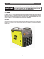
ESP-101
Plasma Arc Cutting System
Instruction Manual (English)
This manual provides installation and operation instructions for the following ESP-101 cutting packages starting with Serial
No.: PxxJ943xxx
Consoles:
P/N 0558004880 - ESP-101 460V
P/N 0558005215 - ESP-101 380-400V CE
0558007871
Be sure this information reaches the operator.
You can get extra copies through your supplier.
caution
These INSTRUCTIONS are for experienced operators. If you are not fully familiar with the
principles of operation and safe practices for arc welding and cutting equipment, we urge
you to read our booklet, “Precautions and Safe Practices for Arc Welding, Cutting, and
Gouging,” Form 52-529. Do NOT permit untrained persons to install, operate, or maintain
this equipment. Do NOT attempt to install or operate this equipment until you have read
and fully understand these instructions. If you do not fully understand these instructions,
contact your supplier for further information. Be sure to read the Safety Precautions before installing or operating this equipment.
USER RESPONSIBILITY
This equipment will perform in conformity with the description thereof contained in this manual and accompanying labels and/or inserts when installed, operated, maintained and repaired in accordance with the instructions provided. This equipment must be checked periodically. Malfunctioning or poorly maintained equipment
should not be used. Parts that are broken, missing, worn, distorted or contaminated should be replaced immediately. Should such repair or replacement become necessary, the manufacturer recommends that a telephone
or written request for service advice be made to the Authorized Distributor from whom it was purchased.
This equipment or any of its parts should not be altered without the prior written approval of the manufacturer.
The user of this equipment shall have the sole responsibility for any malfunction which results from improper
use, faulty maintenance, damage, improper repair or alteration by anyone other than the manufacturer or a service facility designated by the manufacturer.
READ AND UNDERSTAND THE INSTRUCTION MANUAL BEFORE INSTALLING OR OPERATING.
PROTECT YOURSELF AND OTHERS!
6
TABLE OF CONTENTS
SECTION
TITLE................................................................................................................................................ PAGE
SECTION 1
SECTION 2
2.1 2.2 2.3
2.4
2.5
2.6 SECTION 3
3.1
3.2 3.3 3.4 3.5
3.5.1
3.5.2
3.6
3.6
3.7
3.7.1
3.8
3.9
3.10
Safety Precautions..........................................................................................................................................................9
DESCRIPTION.......................................................................................................................................................................... 11
General . .................................................................................................................................................................................... 11
Scope........................................................................................................................................................................................... 11
ESP-101 Plasma Arc Cutting System: . ............................................................................................................................. 12
Package Ordering Information:.......................................................................................................................................... 13
PT-37 Torch Data...................................................................................................................................................................... 13
System and Optional Accessories...................................................................................................................................... 14
INSTALLATION........................................................................................................................................................................ 15
General . .................................................................................................................................................................................... 15
Equipment Required.............................................................................................................................................................. 15
Placement and Location....................................................................................................................................................... 15
Inspection.................................................................................................................................................................................. 15
Primary Input Connections.................................................................................................................................................. 16
TUA2 Auto-Transformer Primary Input Connections.................................................................................................. 18
Input Air Connection.............................................................................................................................................................. 20
CNC Interface Connection.................................................................................................................................................... 21
CNC Interface Connection (continued)........................................................................................................................... 22
Voltage Divider Adjustment................................................................................................................................................ 23
Output Voltage Sample......................................................................................................................................................... 23
Secondary Output Connections for Mechanized Cutting........................................................................................ 24
PT-37 Torch Installation......................................................................................................................................................... 25
Remote Junction Box Installation...................................................................................................................................... 26
SECTION 4OPERATION.............................................................................................................................................................................. 31
4.1 ESP-101 Controls...................................................................................................................................................................... 31
4.2
Cutting with the ESP-101...................................................................................................................................................... 34
4.3
Electrode Wear.......................................................................................................................................................................... 34
4.4
Standoff and Cut Quality...................................................................................................................................................... 35
4.5
Dross Formation....................................................................................................................................................................... 36
4.6
Common Cutting Issues........................................................................................................................................................ 37
SECTION 5
MAINTENANCE.....................................................................................................................................................................243
SECTION 6
TROUBLESHOOTING..........................................................................................................................................................245
SECTION 7REPLACEMENT PARTS.......................................................................................................................................................253
Diagrams and Parts List..............................................................................................................................attached packet
7
TABLE OF CONTENTS
8
section 1safety precautions
1.0
Safety Precautions
Users of ESAB welding and plasma cutting equipment have the ultimate responsibility for ensuring that
anyone who works on or near the equipment observes all the relevant safety precautions. Safety precautions
must meet the requirements that apply to this type of welding or plasma cutting equipment. The following
recommendations should be observed in addition to the standard regulations that apply to the workplace.
All work must be carried out by trained personnel well acquainted with the operation of the welding or plasma
cutting equipment. Incorrect operation of the equipment may lead to hazardous situations which can result in
injury to the operator and damage to the equipment.
1.
Anyone who uses welding or plasma cutting equipment must be familiar with:
- its operation
- location of emergency stops
- its function
- relevant safety precautions
- welding and / or plasma cutting
2. The operator must ensure that:
- no unauthorized person stationed within the working area of the equipment when it is started up.
- no one is unprotected when the arc is struck.
3. The workplace must:
- be suitable for the purpose
- be free from drafts
4. Personal safety equipment:
- Always wear recommended personal safety equipment, such as safety glasses, flame proof
clothing, safety gloves.
- Do not wear loose fitting items, such as scarves, bracelets, rings, etc., which could become
trapped or cause burns.
5.
General precautions:
- Make sure the return cable is connected securely.
- Work on high voltage equipment may only be carried out by a qualified electrician.
- Appropriate fire extinquishing equipment must be clearly marked and close at hand.
- Lubrication and maintenance must not be carried out on the equipment during operation.
Enclosure Class
The IP code indicates the enclosure class, i.e. the degree of protection against penetration by solid objects or
water. Protection is provided against touch with a finger, penetration of solid objects greater than 12mm and
against spraying water up to 60 degrees from vertical. Equipment marked IP23S may be stored, but is not intended to be used outside during precipitation unless sheltered.
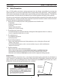
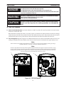
CAUTION
If equipment is placed on a surface that
slopes more than 15°, toppling over may occur. Personal injury and / or significant damage to equipment is possible.
9
Maximum
Tilt Allowed
15°
section 1safety precautions
WARNING
WELDING AND PLASMA CUTTING CAN BE INJURIOUS TO YOURSELF AND
OTHERS. TAKE PRECAUTIONS WHEN WELDING OR CUTTING. ASK FOR
YOUR EMPLOYER’S SAFETY PRACTICES WHICH SHOULD BE BASED ON
MANUFACTURERS’ HAZARD DATA.
ELECTRIC SHOCK - Can kill.
- Install and earth (ground) the welding or plasma cutting unit in accordance with applicable standards.
- Do not touch live electrical parts or electrodes with bare skin, wet gloves or wet clothing.
- Insulate yourself from earth and the workpiece.
- Ensure your working stance is safe.
FUMES AND GASES - Can be dangerous to health.
- Keep your head out of the fumes.
- Use ventilation, extraction at the arc, or both, to take fumes and gases away from your breathing zone
and the general area.
ARC RAYS - Can injure eyes and burn skin.
- Protect your eyes and body. Use the correct welding / plasma cutting screen and filter lens and wear
protective clothing.
- Protect bystanders with suitable screens or curtains.
FIRE HAZARD
- Sparks (spatter) can cause fire. Make sure therefore that there are no inflammable materials nearby.
NOISE - Excessive noise can damage hearing.
- Protect your ears. Use earmuffs or other hearing protection.
- Warn bystanders of the risk.
MALFUNCTION - Call for expert assistance in the event of malfunction.
READ AND UNDERSTAND THE INSTRUCTION MANUAL BEFORE INSTALLING OR OPERATING.
PROTECT YOURSELF AND OTHERS!
CAUTION
This product is solely intended for plasma cutting. Any other
use may result in personal injury and / or equipment damage.
CAUTION
To avoid personal injury and/or equipment
damage, lift using method and attachment
points shown here.
10
section 2description
WARNING
Use the ESAB PT-37 Plasmarc torch with MECHANIZED consoles. Use of torches not designed for use with this console could create an ELECTRIC SHOCK HAZARD.
2.1 General
As shipped, the ESP-101 is fully assembled and ready to cut after being connected to input power, a source of
compressed air, and a PT-37 torch. The ESP-101 system uses the heavy-duty PT-37 (Mechanized Plasma) torch to
deliver cutting power for cutting materials up to 1-1/4 inch (32 mm) thick. Refer to the following pages for descriptions of the ESP-101 packages available as well as performance specifications.
2.2 Scope
The purpose of this manual is to provide the operator with all the information required to install and operate the
ESP-101 Plasma Arc Cutting System. Technical reference material is also provided to assist in troubleshooting the
cutting system.
11
section 2description
2.3
ESP-101 Plasma Arc Cutting System:
The ESP-101 plasma cutting system combines the newly redesigned ESP-101 console and PT-37 torch. The PT-37 plasma
cutting torch is designed to provide increased performance and longer consumable life resulting in higher production
rates at lower costs.
Specifications: ESP-101
Pierces 3/4 inch (19.1 mm); Cuts 1-1/4 inch (32 mm) for Carbon & Stainless Steel
Pierces 3/4 inch (19.1 mm); Cuts 1 inch (25 mm) for Aluminum
Input.........................................................................................460 vac, 3 phase 60 Hz, 25 A
....................................................................... 380/400 vac, 3 phase 50/60 Hz, 30/29 A
Output..................................................................... 100 amps @ 160v - 100% duty cycle
Voltage requirements......................................................... Idle 380-400, 460V, +/- 10%
....................................................................................... Cutting 380-400, 460V, +/- 15%
Air Supply Requirements . ........................500 cfh @ 90 psig (236 l/min @ 6.2 bars)
Efficiency...............................................................................................................................89%
Power Factor........................................................................................................................92%
CE 380-400 vac................................................................................................. *Ssc min 4 MVA
....................................................................................................................... *Zmax 0.039 Ω
Weight:............................................................................................................. 125 lb (56.7 kg)
Duty Cycle: The duty cycle refers to the time as a percentage of a ten-minute period that you can cut at a certain load without overheating. The duty cycle is valid for 40 degrees C.
*Ssc min : Minimum short circuit power on the network in accordance with IEC61000-3-12.
*Zmax : Maximum permissible line on the network impedance in accordance with IEC61000-3-11.
12
section 2description
2.4
Package Ordering Information:
Mechanized Package Ordering Information:
The components that are included in the ESP-101 mechanized packages may be purchased separately by using the appropriate P/N when placing orders. Individual part numbers are listed below:
Available Packages:
ESP-101:
460 V CNC PT-37 with rack 25 ft (7.6 m)................................................................................................................................................ 0558009450
460 V CNC PT-37 with rack 50 ft (15.2 m)............................................................................................................................................. 0558009451
460 V CNC PT-37 w/o rack 25 ft (7.6 m)................................................................................................................................................. 0558009452
460 V CNC PT-37 w/o rack 50 ft (15.2 m).............................................................................................................................................. 0558009453
380-400 V CE CNC PT-37 with rack 25 ft (7.6 m)................................................................................................................................. 0558009458
380-400 V CE CNC PT-37 with rack 50 ft (15.2 m).............................................................................................................................. 0558009459
380-400 V CE CNC PT-37 w/o rack 17 ft (5.2 m).................................................................................................................................. 0558009460
380-400 V CE CNC PT-37 w/o rack 25 ft (7.6 m).................................................................................................................................. 0558009461
380-400 V CE CNC PT-37 w/o rack 50 ft (15.2 m)............................................................................................................................... 0558009462
ESP-101 Multi-Voltage:
The ESP-101 multi-voltage console ships as a ESP-101 460 V console and a separate TUA2 Auto-Transformer.
208-575 V CNC PT-37 with rack 25 ft (7.6 m)....................................................................................................................................... 0558009454
208-575 V CNC PT-37 with rack 50 ft (15.2 m).................................................................................................................................... 0558009455
208-575 V CNC PT-37 w/o rack 25 ft (7.6 m)........................................................................................................................................ 0558009456
208-575 V CNC PT-37 w/o rack 50 ft (15.2 m)..................................................................................................................................... 0558009457
ESP-101 Consoles:
460 V Console................................................................................................................................................................................................... 0558004880
380-400 V CE Console.................................................................................................................................................................................... 0558005215
Multi-Voltage Consoles:
The ESP-101 multi-voltage console ships as a ESP-101 460 V console and a separate TUA2 Auto-Transformer.
208, 230, 400, 460, 475, 500, 575 V............................................................................................................................................................ 0558004881
WARNING
2.5
DO NOT use oxygen with this torch! A hazardous fire may
result.
PT-37 Torch Data
ESP-101 mechanized console uses the PT-37 torch. For cut data information, breakdown of parts, dimensions and maintenance refer to
torch manual.
PT-37 Torches:
PT-37 Torch with rack 4.5' (1.4m)...........................0558004860
PT-37 Torch with rack 17' (5.2m)............................0558004861
PT-37 Torch with rack 25' (7.6m)............................0558004862
PT-37 Torch with rack 50' (15.2m)..........................0558004863
PT-37 Torch w/o rack 4.5' (1.4m).............................0558004894
PT-37 Torch w/o rack 17' (5.2m).............................0558004895
PT-37 Torch w/o rack 25' (7.6m).............................0558004896
PT-37 Torch w/o rack 50' (15.2m)..........................0558004897
13
section 2description
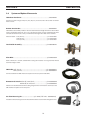
2.6 System and Optional Accessories
TUA2 Auto-Tranformer............................................................................................0459145880
Converts an input voltage of 208, 230, 400, 475, 500, or 575 V to 460 V for use with an ESP-101
460 V console.
Remote Junction Box...............................................................................................0558004887
The Remote Junction Box provides a means to extend the total length of the PT-37 Torch. When
used in combination with 50 ft., 75 ft., or 100 ft. extension cables, and any standard length of PT37 Plasma Torch from 4.5 ft. to 50 ft., a maximum torch length of 150 feet can be achieved.
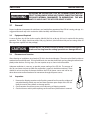
Extension Cable 50 ft. (15.2 m)....................................................................................... p/n 0558004888
75 ft. (22.9 m)...................................................................................... p/n 0558009266
100 ft. (30.5 m).................................................................................... p/n 0558004889
Torch Holder Assembly....................................................................................p/n 0558005926
Plate Rider...............................................................................................................p/n 0560936972
Used to maintain a constant standoff while cutting thin materials or using machines without
automatic height control.
CNC Cable 25 ft. (7.6 m)....................................................................................p/n 0558008833
50 ft. (15.2 m).................................................................................p/n 0558008834
Connects between the CNC interface receptacle on the rear panel and the CNC.
Remote Hand Switch with 25 ft. (7.6 m) lead........................................... p/n 0558005548
with 50 ft. (15.2 m) lead........................................ p/n 0558005549
Enables non-automated mechanized cutting using the PT-37 or PT-38 torch. Connects to the
CNC interface receptacle on the rear panel.
Gas Flow Measuring Kit . ...............................p/n 19765 ("CE" units - 0558000739)
Valuable troubleshooting tool allows measurement of the actual air flow through the torch.
14
section 3installation
WARNING
Installing or placing any type of filtering device will restrict the volume of intake air, thereby subjecting the power source internal components to overheating. The warranty is void if any type of filter device is used.
3.1 General
Proper installation is important for satisfactory and trouble-free operation of the ESP-101 cutting package. It is
suggested that each step in this section be studied carefully and followed closely.
3.2 Equipment Required
A source of clean, dry, oil-free air that supplies 500 cfh (236 l/m) at 90 psig (6.2 bars) is required for the cutting
operation. The air supply should not exceed 150 psig (10.3 bars) (the maximum inlet pressure rating of the air
filter-regulator supplied with the package).
caution
Position the ESP-101 at least 10 feet (3 meters) from theGB
cutting area.
Sparks and hot slag from the cutting operation can damage the unit.
5.1
3.3 Placement and Location
Lifting instruc
With
source
After selecting an installation site, place the ESP-101 in the desired location. The unit may be lifted
by power
either an
overhead crane or forklift truck. If using forklift truck, be sure that the lift forks are long enough to extend completely under the base. If using straps, use two separate straps as shown in the illustration.
Adequate ventilation is necessary to provide proper cooling of the ESP-101. The amount of
dirt, dust, and excessive heat to which the equipment is exposed, should be minimized. There
should be at least one foot of clearance between the ESP-101 power source and wall or any
other obstruction to allow freedom of air movement through the power source.
3.4 Inspection
1. Remove the shipping container and all packing material and inspect for evidence of
concealed damage which may not have been apparent upon receipt of the ESP-101.
Notify the carrier of any defects or damage at once.
2. Check container for any loose parts prior to disposing of shipping materials.
3. Check air louvers and any other openings to ensure that any obstruction is removed.
5.2
Placing
Position the welding pow
obstructed.
15
section 3installation
WARNING
3.5
ELECTRIC SHOCK CAN KILL! Precautionary measures should
be taken to provide maximum protection against electrical shock. Be sure that all power is off by opening the line
(wall) disconnect switch and by unplugging the power
cord to the unit when connections are made inside of the
power source.
Primary Input Connections
The ESP-101 460V consoles are equipped
with approximately 15 ft. of 4-conductor
input power cable for 3 phase connection.
See specification section or rating plate.
A.
STANDARD UNITS
(NON-CE)
PHASE
3
L1
L2
CE UNITS
(EUROPE)
PHASE
3
Black
L1
Brown
Red
L2
Black
L3
White
L3
Gray
GND
Green
GND
Green/Yel
460V
CUSTOMER FUSED LINE DISCONNECT SWITCH
(See Table 3-1)
PRIMARY INPUT
POWER CABLE
B.
380-400V
GND
L3
L2
L1
Figure 3-1. Input Connections
16
section 3installation
WARNING
ELECTRIC SHOCK CAN KILL! Before making electrical input connections to the power source, "Machinery Lockout Procedures" should be employed. If the connections are to be
made from a line disconnect switch, place the switch in the
off position and padlock it to prevent inadvertent tripping.
If the connection is made from a fusebox, remove the corresponding fuses and padlock the box cover. If it is not possible to use padlocks, attach a red tag to the line disconnect
switch (or fuse box) warning others that the circuit is being
worked on.
WARNING
The chassis must be connected to an approved electrical
ground. Failure to do so may result in electrical shock, severe burns or death.
WARNING
Before making any connections to the power source output terminals, make sure that all primary input power to
the power source is deenergized (off) at the main disconnect switch and that the input power cable is unplugged.
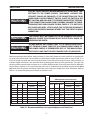
Before connecting to input power, make sure there is a line (wall) disconnect switch with fuses or circuit breakers at the main power panel. You may either use the factory-installed input power cable 4/c, type SO (90 °C), 15
ft (4.6 m) length or provide your own input power leads. If you choose to provide your own, make sure they are
insulated copper conductors. You must have three (3 phase) power leads and one ground wire. The wires may
be heavy rubber covered cable or may be run in a solid or flexible conduit. Ensure the ground lead is sufficiently
long inside the machine. In an event where the power cord is pulled from the machine, the ground lead must
not break from the ground connection before the power leads have broken from their connection. Refer to
Table 3-1 for recommended input conductors and line fuse sizes.
ESP-101
Input Requirements
Volts
Phase Amps
ESP-101
(With Optional Auto-transformer)
Input & Gnd
Fuse
Conductor
Size
CU/AWG
Amps
40
380(CE)
3
30
6 mm
400(CE)
3
29
6 mm
460
3
25
8
2
2
Input Requirements
Volts
208
Phase Amps
3
53
Input & Gnd
Fuse
Conductor
Size
CU/AWG
Amps
6
70
40
230
3
50
6
70
35
400
3
29
6 mm2
40
460
3
25
8
35
475
3
24
8
35
500
3
22
10
30
575
3
18
10
25
Table 3-1. Recommended Sizes For Input Conductors and Line Fuses
17
section 3installation
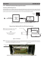
3.5.1 TUA2 Auto-Transformer Primary Input Connections
Connecting a Multi-Voltage Version
The ESP-101 460V version is equipped with an input power cable which may be used to connect to the output of the TUA2
Auto-Transformer. You may either use the factory-installed input power cable (4/c, type SO (90 °C) or provide your own input power leads. If you choose to provide your own, make sure they are insulated copper conductors. You must have three
(3 phase) power leads and one ground wire. Refer to Table 3-1 for recommended input conductors.
3-phase w/
ground
PT-37 Torch
4.5’, 17', 25', 50’
ESP-101
460V
Console
from 460 V
terminals
TUA2
AutoTransformer
to appropriate supply
voltage terminals
Figure 3-2a. Connection Diagram for TUA2 Auto-Transformer
Primary Power Cable from ESP-101 to TUA2 Auto-Transformer
Step 1: Begin by preparing the power cable,
then positioning in the TUA2 as shown.
Upper Strain Relief
10"
(254 mm)
7"
(178 mm)
3"
(76 mm)
Note:
L1
L2
L1, L2 & L3 strip wires 3/8" (9.5 mm) .
GND wire strip 1" (25.4 mm) or
5/16" ring terminal.
L3
16"
(406 mm)
Figure 3-2b. Primary Power Cable from ESP-101 to TUA2 Auto-Transformer
Step 2: Route the power cable through the upper strain relief of the TUA2 Auto-Transformer as shown below. Connect L1,
L2, L3 leads to the 460 V terminals. Connect the ground lead to the forward ground stud. Ensure all connections
are secure. Do not overtighten the strain relief.
460 V Terminals
To ESP-101 460 V
console
Figure 3-2c. Primary Power Cable from ESP-101 to TUA2 Auto-Transformer 460 V Terminals
18
GND
section 3installation
caution
Ensure three input power jumper cables are connected properly to the
Auto-Transformer for your input power.
The TUA2 Auto-Transformer is not equipped with an input power cable. A 4/c, type SO (90 °C) cable or equivalent is recommended. Ensure they are insulated copper conductors. You must have three (3 phase) power leads and one ground wire.
Select an input power cable size corresponding to the input supply voltage listed in Table 3.1.
Primary Power Cable from Fused Line Disconnect Switch
to TUA2 Auto-Transformer
Step 1: Begin by preparing the power cable, then positioning in the TUA2 as shown:
Lower Strain Relief
10"
(254 mm)
10 1/2"
(266.7 mm)
Note:
8"
(203.2 mm)
L1, L2 & L3 strip wires 3/8" (9.5 mm) .
GND wire strip 1" (25.4 mm) or
5/16" ring terminal.
L1
L2
L3
GND
18"
(457.2 mm)
Figure 3-3a. Primary Power Cable from Fused Line Disconnect Switch
to TUA2 Auto-Transformer
Step 2: Route the power cable through the lower strain relief of the TUA2 Auto-Transformer as shown below. Connect L1,
L2, L3 leads to the voltage terminals that match your input power supply voltage. Connect the ground lead to the
rear ground stud. Ensure all connections are secure. Do not overtighten the strain relief.
To ESP-101 460 V
console
To Fused Line
Disconnect Switch
Appropriate supply
voltage terminals
Ground Connection
Figure 3-3b. Primary Power Cable from Fused Line Disconnect Switch
to TUA2 Auto-Transformer appropriate supply voltage terminals
(575 V pictured)
19
section 3installation
3.5.2 Input Air Connection
Connect your air supply to the inlet connection of the filter/regulator.
Pre-filtered DRY AIR SUPPLY (Customer Supplied)
(90 - 150 psi / 6.2 - 10.3 bars)
Replace fuse with Slo-Blo, 2 Amp, 600 V only
WARNING
make sure the power source is
SWITCHED off BEFORE REMOVING FUSE.
Figure 3-4. Input Connections / Fuse Replacement
20
section 3installation
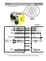
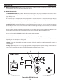
3.6
CNC Interface Connection
Front View
Power Source
ESP-101
CNC
Start
Corner
EXT REF
Motion
allow
START #13
M
M (J6-4) GRN
COMMON
#14
N
N (J6-1) BLU
CORNER / EXT REF
#5
E
E
arc ON common
#7
G
G (J2-5) VIO
(arc ON)
ARC ON
#9
I
I
(arc ON)
VDR +
#3
C
C (J1-2) ORN
VDR -
#8
H
H (J1-3) GRY
CURRENT ref +
#12
L
L
(J4-1) YEL
CURRENT ref -
#10
j
j
(J4-2) BLK
#6
f
f
#4
d
d
#11
k
k
#1
A
A (J6-7) BRN
#2
B
B (J6-1) RED
(J6-6) WHT
(J2-6) WHT
start
COMMON
CORNER / EXT REF
(+)
For autoMATIC
height control
(-)
optional
remote
current
control
active
driver
Optional
input
FAULT
+(12-30) VDC FAULT SUPPLY
Note:
External
Current
command
If replacing the ESP-100 with an ESP-101, reversing wires 1 and 2 on the CNC cable may be necessary for proper polarity.
Figure 3-5. Mechanical Cutting Interface Diagram CNC Interface Connection
21
section 3installation
3.6
CNC Interface Connection (continued)
Start signal (pin M)
Use a relay to connect this pin to “Common” (pin N) to start the cutting process.
If a transistor is used for this signal, then the positive potential must be connected to pin M and the common/negative to
pin N. This would require a transistor capable of blocking 24 VDC and sinking more than 11 mA.
Corner / External Reference (pin E)
Use a relay to connect this pin to “Common” (pin N) to set the cut current reference signal to the external source- pins L
and J.
If a transistor is used for this signal, then the positive potential must be connected to pin E and the common/negative to
pin N.
Arc On (pins G and I)
These pins will be connected together, via normally open relay contacts that close when the plasma system has established work current. This signal is also referred to as “Motion Allow” or “Arc-Established”.
Voltage Divider (VDR) for Automatic Height Control (pins C and H)
Pin C is the positive connection to the Voltage Divider Network. Pin H is the negative connection.
See section 3.7 for Voltage Divider default values and adjustment instructions.
Current Reference for Optional Remote Current Control (pins L and J)
This signal should be provided by an active driver that is referenced to ground. The signal is received (inside the power
source) by a differential amplifier, insuring adequate input impedance for the driver. It is safe to connect output signal
directly to pin L and the control common directly to pin J.
The reference signal will be scaled as follows:
-
-
-
0 V input, 20 Amps output
10 V input, 100 Amps output
20 Amps + 8 Amps per Volt input
Optional Input: Fault (pins A and B)
This is a power source fault signal that can be used to signal the external control that the plasma is in a fault condition. It
is important to note that this is a transistorized and therefore polarized signal. A source voltage of at least 12 VDC, but no
more than 30 VDC, should be applied to pin B. The fault signal will then come out on pin A.
22
section 3installation
WARNING
3.7
Make sure power switch on console is in OFF position and
primary input power is de-energized.
Voltage Divider Adjustment
It may be necessary to adjust the Voltage Divider or VDR to match the particular height control system. There are two default settings for the ESP-101 models as shipped from the factory:
•
STANDARD UNITS (Non-CE): 750 ohms (21:1)
•
CE UNITS (Europe): 789 ohms (20:1)
If the height control system does not match the factory default setting, matching can be accomplished by adjusting the
VDR potentiometer on the Current Sensor PCB4 located behind the left side panel.
1. Place ohm meter leads between P1-2 (orn) & P1-3 (gry). Adjust R2 to achieve the desired divide ratio for the
particular height control system used. For example:
•
•
16:1 ratio 1000 ohms
18:1 ratio 882 ohms
•
•
21:1 ratio 750 ohms
20:1 ratio 789 ohms
Note:
Ohm meter readings can also be taken at the CNC receptacle on the rear panel of the machine, between pins C and H.
2. If desired, additional minor adjustments of the VDR potentiometer may be made. Any adjustments should be
performed by a qualified technician.
+
-
Potentiometer
(R2)
P1
3.7.1Output Voltage Sample
Output Voltage Sample - Some Cutting Machines sample the full output voltage of the plasma system to control the torch
height and to determine when to start moving. The full output voltage is available within the machine on a pair of male
spade terminals (J3 and J4).
1. Remove insulated terminals to provide access to the male
spade terminals. (If needed, the insulated terminals may
then be used to terminate the voltage pickup wires.)
J4
(+)
Output Voltage Sample
23
J3
(-)
Installation, Operation, and Maintenance Manual for the
section 3installation
WARNING
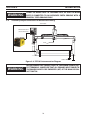
3.8
SHADOW
Clamp the work cable to the work piece. Be sure the work
piece is connected to an approved earth ground with a
properly sized ground cable.
GANTRY SHAPE CUTTING MACHINE
Secondary Output Connections for Mechanized Cutting
Torch Cable
CNC Control Cable
(back connection)
PT-37
Figure 3-6. ESP-101 Interconnection Diagram
WARNING
SAFETY GROUND
Before making any connections to the power source output terminals, make sure that all primary input power to
the power source is de energized (off) at the main disconnect switch.
411 S. Ebenezer Road
Florence, SC 29501-0545
24
section 3installation
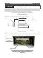
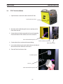
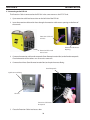
3.9
PT-37 Torch Installation
1. Open lead access door on the left side of the ESP-101.
Torch Lead Access Door
2. Route the torch cable through the access opening on the
front of the console.
3. Connect the torch cable receptacle to the panel receptacle.
Check orientation of the sockets to ensure a correct fit.
Torch Cable Male Receptacle
4. Connect the air hose to the quick-connect fitting.
Torch Lead Access Opening
5. Insert work cable plug into work cable socket on the front of
the console and turn clockwise until secure.
6. Close the Torch Lead access door.
Panel Receptacle
Air Hose
Torch Cable Male Receptacle
25
Work Cable Socket
section 3installation
WARNING
Make sure power switch on console is in OFF position and
primary input power is de-energized.
3.10Remote Junction Box Installation
The Remote Junction Box (RJB) provides a means to extend the total length of the PT-37 Torch. A Remote Junction Box is
used in combination with 50’, 75' or 100’ extension cable and any standard length of PT-37 Plasma Torch from 4.5’ to 50’, to
create a combined maximum torch length of 150 feet.
Installation of a Remote Junction Box requires minor modifications to the ESP-101 power supply, mounting of the box itself,
and connection of the extension cable. Use the diagram and steps below for installation.
3-phase w/
ground
Note:
See section 2.6 System and Optional Accessories for Remote
Junction Box and Extension Cable ordering information.
PT-37 Torch
4.5’, 17', 25', 50’
Remote
Junction
Box
Extension Cable
50’, 75', 100’
ESP-101
Figure 3-7. Connection Diagram for Remote Junction Box
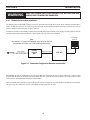
Description of ESP-101 modification: The wiring modification (interconnect plug reversal) redirects the control signal
from the ESP-101 internal solenoid, to the pins within the torch connection panel receptacle. The control signal is then
diverted to the solenoid within the Remote Junction Box.
The hose modification (solenoid air bypass) directs the system air supply to the solenoid within the Remote Junction Box.
This ensures air at a sufficient pressure is immediately available to the PT-37 torch.
26
section 3installation
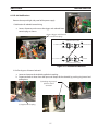
A. ESP-101 Modifications
Remove the top and right side panel of the power supply.
1. Redirection of solenoid control wiring:
a. Locate, disconnect and reverse the trigger and solenoid interconnect plugs as shown.
Reverse Trigger and Solenoid
Interconnect plugs
TRIGGER INTERCONNECT (UPPER)
From PANEL RECEPTACLE
To TRIGGER CONTROL
To SOLENOID
From SOLENOID CONTROL
SOLENOID INTERCONNECT (LOWER)
Figure 3-8. Interconnect Reversal
2. Air flow by-pass of internal solenoid:
a. Locate and remove the included supplied air coupling.
b. Disconnect both air hoses from the input and output of the solenoid, by pushing ring inward and
pulling hose.
(b) Pushing ring inward pull hose out of
connector
(a) Supplied Air Coupling
27
section 3installation
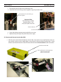
c. Re-route the Input Air Hose over to the output side.
d. Couple the free ends of the gas tubes together using the provided union.
(c) Re-route Input Air Hose
(d) Couple the free ends of the gas
tubes together
Important Note:
Ensure tubing is securely
fastened at least 1 inch
away from pilot arc resistor.
Pilot Arc Resistor
(e) Secure the tubing
e. Secure the tubing to prevent contact with pilot arc resistor.
f. Replace the top and right side panel of the power supply.
B. Mounting the Remote Junction Box (RJB)
1. With the cover removed from the Remote Junction Box, mount the base to a rigid location on the cutting machine, robot, or other suitable object, using at least 2 of the provided mounting holes. Orient
the box such that the Extension Cable will enter the end of the RJB not marked for torch connection.
Remote Junction Box
Torch and Extension Cable Openings
(typical at each end of
Remote Junction Box)
28
section 3installation
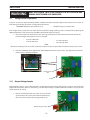
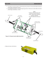
2. Insert the free end of the Extension Cable through the grommet on the end of the RJB and make the
power and gas connections as shown.
3. Insert the free end of the PT-37 Torch through the grommet on the other end of the RJB and make the
power and gas connections as shown.
To PT-37 Torch
Note:
Extension Cable connections from
the ESP-101 must be connected
on the solenoid wiring side of the
Remote junction Box.
(Torch connection side is labeled.)
Torch Cable
Air Connection
Extension Cable
Power Connection
From ESP-101
Torch Cable
Power Connection
Figure 3-9. Remote Junction Box Connections
Extension Cable
Air Connection
Extension Cable
4. Replace all covers and hardware.
29
section 3installation
C. Connecting to the ESP-101
The Extension Cable is connected to the ESP-101 in the same manner as the PT-37 Torch.
1. Open extension cable lead access door on the left side of the ESP-101.
2. Insert the extension cable and air hose through the extension cable access opening on the front of
the console.
Extension Cable and
Air Hose
Extension Cable Lead
Access Door
Extension Cable Access
Opening
3. Connect the extension cable male receptacle (from Remote Junction Box) to the female receptacle.
Check orientation of the sockets so as to ensure a correct fit.
4. Connect the air hose (from Remote Junction Box) to the quick-connect fitting.
Panel Receptacle
Quick-connect Fitting
Air Hose
Extension Cable Male
Receptacle
5. Close the Extension Cable Lead access door.
30
section 4
danger
operation
ELECTRIC SHOCK can kill.
• Do NOT operate the unit with the cover removed.
• Do NOT apply power to the unit while holding or carrying the unit.
• Do NOT touch any torch parts forward of the torch handle (nozzle, heat shield, electrode, etc.) with power switch on.
WARNING
ARC RAYS can burn eyes and skin; NOISE can damage hearing.
caution
Position the ESP-101 at least 10 feet (3 meters) from the cutting area.
Sparks and hot slag from the cutting operation can damage the
unit.
• Wear welding helmet with No. 6 or 7 lens shade.
• Wear eye, ear, and body protection.
4.1 ESP-101 Controls
A. Power Switch (ON-OFF)/(I-O). Turn knob clockwise to "ON" ("I") position for normal operation. Turn knob counterclockwise to switch "OFF" ("O").
Note that with the switch in the "on" ("I") position, power is provided to the main transformer and the low voltage
control circuitry. In the "off" ("O") position, the unit is shut down; however, power is still present in the unit. To remove
power from the power source, power must be disconnected at the line disconnect switch or the fuse box.
B. Pressure Regulator. Regulates cut gas pressure. Rotate clockwise to increase and counterclockwise to decrease. Pressure
reading is indicated on the lower display screen. Pressure unit of measure is indicated on the upper display screen.
Note:
With or without Junction Box installed: When using 4.5' (1.4 m) or 17' (5.2 m) torch assemblies, plasma gas settings
should be reduced 5 - 10 psi (.35 - .69 bar) for optimum performance.
Note:
The unit is shipped from the factory with the regulator adjusted to deliver 80 psig (5.5 bar) to the torch from a 95 psig
(6.5 bar) supply. If supply pressure to the machine is greater than 95 psig (6.5 bar) up to the maximum recommended
150 psig (10.3 bar), rotate pressure regulator knob counterclockwise to reduce the pressure delivered to the torch
back to 80 psig (5.5 bar). Follow GAS TEST instructions, see D.2.
A
B
Figure 4-1. ESP-101 Controls
31
section 4
operation
C. Output Current Control. Adjustable from 20 to 100 amperes. Calibration marks are to provide a guide in setting current. For settings refer to cut data charts in the torch manual.
D. Mode Selector Switch.
1. Consumable Check (up position) - When placed in this position, the proper installation and operation of the
consumables are verified by sending a series of gas pulses through the torch. PIP (Parts in Place) is indicated on the
upper display screen.
An error message will be displayed if improper operation is detected. Err (Error) is indicated on the upper display
screen. The Error code is indicated on the lower display screen. Refer to Section 6.2 List of Help Codes.
Be sure to place switch in OPERATE position before starting cutting operation.
2. Gas Test (center position) - The display screen will indicate flowing air pressure. Pressure reading is indicated on
the lower display screen. Pressure unit of measure is indicated on the upper display screen (PSI or Bar). See section 7.4
for selecting air pressure units of measure.
The air regulator should be adjusted to recommended pressure before cutting operations. Allow air to flow for a few
minutes. This should remove any condensation that may have accumulated during shutdown period.
Be sure to place switch in OPERATE position before starting cutting operation.
3. Operate (down position) - Place switch in this position for cutting and gouging operations.
E. Process Selector Switch. The process switch allows for selection of the output characteristics of the power source
depending on the cutting process being used.
1. Normal. Setting for all standard plate cutting operations. (The pilot arc will not re-strike automatically. Requires a
new start signal.)
2. Gouge. Optimizes power source for gouging operations. Gouging requires higher arc voltages. In this mode the
power source allows higher operating arc voltage limiting the output current to 85 amps.
C
D
E
Figure 4-2a. ESP-101 Controls
32
section 4
operation
F. Display Screens.
Voltmeter (upper) - Displays DC output voltage.
Ammeter (lower) - Displays output current setting.
The voltmeter and ammeter screens alternately display Model, Test and the Software version along with help code
information (see Section 6.2 List of Help Codes).
When unit is initially switched on the Model, PIP (Parts in Place) and Software version will be briefly displayed. Lower
display will then show Current Setting.
Important Note:
If after the initial sequence the display does not show the Current Setting but reverts back to displaying the model "ESP101", the machine has detected a premature torch trigger condition. Disengage the torch trigger and restart the machine.
(As a safety precaution, the ESP-101 will not power up with the torch trigger engaged.)
G. Temp Indicator Lamp.
The amber lamp will illuminate to indicate an internal overheating condition has occurred, one of the thermal switches
has opened. User control of the power source will be interrupted and the unit will shut down to protect critical components. Leave the power on to allow the fan time to cool off the unit. Once cooled to a safe temperature, the thermal
switch will automatically reset and output control will be restored.
H. Fault Indicator Lamp.
The red lamp will illuminate to indicate an error has occurred, operator attention is required. See item F. Display Screens
and refer to Section 6.2 List of Help Codes.
Note:
Most fault signals will remain on for a minimum of 10 seconds.
Unit will reset automatically after faults are cleared except for over-current protection.
Error Indication:
An error message will be displayed if improper operation is detected. Err (Error) is indicated on the upper display
screen. The Error code is indicated on the lower display screen. Refer to Section 6.2 List of Help Codes.
G
H
F
Figure 4-2b. ESP-101 Controls
33
section 4
operation
WARNING
Make sure power switch on UNIT is in OFF position before
working on the torch.
WARNING
The PT-37 torch head acts in conjunction with the circuitry
within the power source to prevent the torch from being
energized with high voltage if the torch switch is accidentally closed when the shield is removed. Always replace
torch with the proper torch manufactured by ESAB since
it alone contains ESAB's safety interlock.
4.2
Cutting with the ESP-101
A. Make sure that the wall disconnect switch is on and air is supplied to machine.
B. Turn on the front panel power switch.
C. Place MODE selector switch to "GAS TEST". Set Pressure Regulator to 80 psig (5.5 bar).
D. Place MODE selector switch to "OPERATE".
E. Place Process selector switch to either "Normal" or "Gouging".
F. For in depth instructions refer to torch manual for complete operation and maintenance.
G. Periodically check torch head assembly. Replace if worn or damaged.
H. Torch cable should be inspected periodically. If there are any cuts through the protective sheath or wire insulation,
replace the cable.
caution
4.3
REPLACE ELECTRODE BEFORE WEAR BECOMES DEEPER THAN .060"
INCH (1.5 MM)
Electrode Wear
If the electrode has a pit which is more than .06" (1.5mm) deep at its center, it must be replaced. This is done by unscrewing the electrode in a counter-clockwise direction from the piston. If the electrode is used beyond this recommended
wear limit, damage to the torch and power source may occur. Nozzle life is also greatly reduced when using the electrode
below the recommended limit.
WORN
NEW
Figure 4-3. Electrode Wear Limit
34
section 4
4.4
operation
Standoff and Cut Quality
Standoff (Arc Voltage) has a direct influence on cut quality and squareness. It is recommended that prior to
cutting, that all cutting parameters are set to the manufacturer’s suggested conditions. Refer to the Operation
section Process Data in the torch manual for recommendations. A sample cut should be made using actual part
material followed by close examination of the part.
If the cut face of the part has excessive bevel or rounded top edge, it may be that the standoff is set too high.
When standoff is controlled by an arc voltage height control, reducing the arc voltage setting will reduce the
standoff.
Lower the standoff until the excessive bevel or rounded top edge disappears. Note that on material thicknesses
of 1/4" (6.4 mm) or greater, a standoff too close may result in a negative cut angle.
STANDOFF
ARC
VOLTAGE
LAG LINES
Figure 4-4. Cut Quality
A
POSITIVE (+) CUT ANGLE
Bottom dimension “B” is
greater than dimension “A”
B
NEGATIVE (-) CUT ANGLE
A
Bottom dimension “B” is less
than dimension “A”
B
Figure 4-5. Cut Angle
35
section 4
4.5
operation
Dross Formation
Cutting speed, gas selection and variations in metal composition contribute to dross formation. The correct cutting standoff also has an influence on dross formation. If the arc voltage is set too high, the cut angle becomes
positive. In addition, dross forms on the bottom edge of the part. This dross can be tenacious and require chipping and grinding for removal. Setting the cutting voltage too low results in undercutting the parts or negative
cut angle. Dross formation occurs but in most cases it is easily removed.
Top Dross
Top dross usually appears as splatter near the top edge of the kerf. This is a result of torch standoff (arc voltage)
set too high or cutting speed set too fast. Most operators use the parameter charts for recommended speed. The
most common problem is torch standoff or arc voltage control. Simply lower the voltage settings in increments
of 5 volts until the top dross disappears. If an arc voltage control is not used, the torch can be lowered manually
until the dross disappears.
TOP DROSS:
Splatter appears on the top edge of
both pieces of the plate.
Lower the voltage in increments of 5
volts DC (maximum) until top dross
disappears.
HIGH SPEED DROSS:
Fine roll over dross that welds to bottom of edge. Cleaning requires chipping or grinding.
LOW SPEED DROSS
Globular dross that forms in large deposits. Comes off very easily.
Figure 4-6. Dross Formation
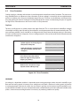
SUMMARY
Arc voltage is a dependent variable. It is dependent upon cutting amperage, nozzle size, torch standoff, cut gas
flow rate and cutting speed. An increase in arc voltage can result from a decrease in cutting speed, an increase
in cutting amperage, a decrease in nozzle size, an increase in gas flow and an increase in torch standoff. Assuming that all of the variables are set as recommended, torch standoff becomes the most influential variable to the
process. Good and accurate height control is a necessity in producing excellent cut quality.
36
section 4
4.6
operation
Common Cutting Issues
Listed below are common cutting problems followed by the probable cause of each. If problems are determined to be caused
by the ESP-101, refer to the maintenance and troubleshooting sections of this manual. If the problem is not corrected after
referring to the maintenance and troubleshooting sections, contact your ESAB distributor.
A. Insufficient Penetration.
1.
2.
3.
4.
5.
6.
Current too low.
Cutting speed too fast.
Damaged cutting nozzle.
Improper air pressure.
Low air flow rate.
Standoff too high - Nozzle to plate distance.
B. Main Arc Extinguishes.
1. Cutting speed too slow.
2. Worn electrode.
3. Standoff too high - Nozzle to plate distance.
C. Dross Formation. (In some materials and thicknesses, it may be impossible to get dross-free cuts.)
1.
2.
3.
4.
5.
Current too low.
Cutting speed too fast or too slow.
Improper air pressure.
Faulty nozzle or electrode.
Low air flow rate.
D. Double Arcing. (Damaged Nozzle Orifice.)
1.
2.
3.
4.
5.
Low air pressure.
Damaged cutting nozzle.
Loose cutting nozzle.
Heavy spatter accumulation on nozzle.
Nozzle contact with workpiece during starting or cutting operation.
E.Uneven Arc.
1. Damaged cutting nozzle or worn electrode.
2. Heavy spatter accumalation on nozzle or torch heat shield.
F.Unstable Cutting Conditions.
1. Incorrect cutting speed.
2. Loose cable or hose connections.
3. Electrode and/or cutting nozzle in poor condition.
G. Main Arc Does Not Strike.
H. Poor Consumable Life.
1. Worn electrode.
2. Loose connections.
3. Work cable not attached.
1.
2.
3.
4.
Improper air pressure.
Contaminated air supply.
Low air flow rate.
Incorrect current setting for consumable set installed in torch.
37
section 4
operation
38