1
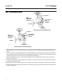
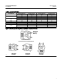
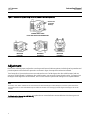
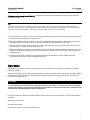
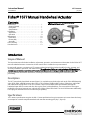
Instruction Manual
1077 Actuator
D101296X012
July 2012
Fisherr 1077 Manual Handwheel Actuator
Contents
Introduction . . . . . . . . . . . . . . . . . . . . . . . . . . . . . . . . . . . 1
Scope of Manual . . . . . . . . . . . . . . . . . . . . . . . . . . . . . 1
Description . . . . . . . . . . . . . . . . . . . . . . . . . . . . . . . . . 1
Specifications . . . . . . . . . . . . . . . . . . . . . . . . . . . . . . . 1
Installation . . . . . . . . . . . . . . . . . . . . . . . . . . . . . . . . . . . . 3
Adjustment . . . . . . . . . . . . . . . . . . . . . . . . . . . . . . . . 8
Operation . . . . . . . . . . . . . . . . . . . . . . . . . . . . . . . . . . 9
Maintenance . . . . . . . . . . . . . . . . . . . . . . . . . . . . . . . . . 10
Lubrication . . . . . . . . . . . . . . . . . . . . . . . . . . . . . . . . 10
Disassembly . . . . . . . . . . . . . . . . . . . . . . . . . . . . . . . 11
Assembly . . . . . . . . . . . . . . . . . . . . . . . . . . . . . . . . . . 11
Parts Ordering . . . . . . . . . . . . . . . . . . . . . . . . . . . . . . . . 13
Parts Reference . . . . . . . . . . . . . . . . . . . . . . . . . . . . . . . 13
Figure 1. Fisher 1077 Handwheel Actuator
Mounted on a V150 Valve
W8176-1
Introduction
Scope of Manual
This instruction manual includes installation, adjustment, operation, and maintenance information for the Fisher 1077
manual handwheel actuator. Instructions for the control valve is included in a separate manual.
Do not install, operate, or maintain a 1077 actuator without being fully trained and qualified in valve, actuator, and
accessory installation, operation, and maintenance. To avoid personal injury or property damage, it is important to
carefully read, understand, and follow all the contents of this manual, including all safety cautions and warnings. If you
have any questions about these instructions, contact your Emerson Process Management sales office before
proceeding.
Description
The 1077 manual-only handwheel actuator (figure 1) is used with rotary-shaft valves such as the Fisher 9500 butterfly
valve, 8532, 8560, and 8580 eccentric disc valves, V150, V200 and V300 Vee-Ball™ valves, V250 valves, and CV500
and V500 eccentric plug valves. In the 1077 actuator, torque is transmitted from the handwheel through the
handwheel input shaft to a worm and drive sleeve gear (sector) with splined bore. The worm and drive sleeve gear
multiply the torque and transmit it to a splined valve shaft or splined stub shaft. The size 10-KE:6 actuator additionally
has a spur gear reduction drive for increased torque capability.
Specifications
1077 actuator specifications are given in table 1. Some specifications for a given actuator as it comes from the factory
are stamped on a metal nameplate attached to the actuator mounting yoke (key 7, figure 6).
www.Fisher.com
Instruction Manual
1077 Actuator
July 2012
D101296X012
Table 1. Specifications
Actuator Sizes
See table 2
Acceptable Valve Shaft Diameters
See table 2
Output Torque
See table 2
Wheel-Rim Force
See table 2
Handwheel Turns Required for Full Rotation
See table 2
Handwheel Rotation
Direct Acting Construction: Clockwise handwheel
rotation closes the valve (produces clockwise rotation
of valve shaft) as shown in figure 2
2
Reverse Acting Construction: Clockwise handwheel
rotation closes the valve (produces counterclockwise
rotation of valve shaft) as shown in figure 2
Maximum Output Rotation
0 to 90 degrees
Mounting Positions
J Right-hand (actuator on right side of valve body
when viewed from the body inlet) or
J Left-hand (actuator on left side of valve body when
viewed from the body inlet). Position 1 as shown in
figure 3 is standard; however, the actuator may be
mounted in any of the positions shown in figure 3.
Refer to figure 2 to determine the correct actuator
construction
Approximate Weights
See table 3
Instruction Manual
1077 Actuator
D101296X012
July 2012
Installation
WARNING
Always wear protective gloves, clothing, and eyewear when performing any installation operations to avoid personal
injury.
If installing into an existing application, also refer to the WARNING at the beginning of the Maintenance section in this
instruction manual.
The 1077 actuator is normally shipped mounted on a control valve body. Follow the procedures in the control valve
body instruction manual for valve installation. Then proceed to the Operation section of this manual.
If the actuator has been shipped separately for installation on a valve body, or if the actuator was removed for
maintenance, mount the actuator by following the instructions presented in this section before installing the valve
body in the pipeline.
Individual part key numbers and part descriptions referenced in this procedure are shown in figure 6 and 7 except
where otherwise indicated.
CAUTION
Rotating the valve disc or ball in the wrong direction will damage seals and other internal parts in some valve bodies. If the
drive sleeve gear (key 1A) is not properly positioned, improper disc or ball rotation could result. If there is any doubt as to
whether or not the drive sleeve gear is properly positioned, remove the gearbox cover plate. Use the appropriate view in
figures 3, 4, and 5 to determine that the drive sleeve gear is at the proper end of its rotation.
1. Rotate the valve disc or ball to the closed position. Refer to the separate valve body instruction manual to
determine the closed position. Consult the appropriate valve instruction manual Installation section for valve shaft
orientation marks.
2. Rotate the handwheel (key 5) to move the drive sleeve gear to the position that is to correspond to the closed
position of the valve disc or ball as follows:
For direct acting turn the handwheel so the drive sleeve gear and travel indicator are rotated fully clockwise.
For reverse acting turn the handwheel so the drive sleeve gear and travel indicator are rotated fully counterclockwise.
3. Remove the travel indicator pointer by removing the machine screws. For a size 0-KE actuator only, remove the
O-ring seal from the hub of the drive sleeve gear. Locate the four index marks on the drive sleeve gear hub. Also
locate the index mark on the end of the valve shaft or stub shaft (key 13, figure 7).
4. Proceed as appropriate:
a. For valves with splined shafts, refer to figures 3, 4, and 5 and locate the correct view for the valve body and
mounting position being used. When the actuator is installed, the valve shaft index mark must be aligned with
the proper gear hub index mark.
b. For valves with keyed shafts, compare the position of the stub shaft keyway with the position of the connector
(key 11, figure 7) keyway. Align the stub shaft index mark with the appropriate drive sleeve gear hub index mark
such that the connector keyway will be in line with the valve shaft keyway.
3
Instruction Manual
1077 Actuator
July 2012
D101296X012
Table 2. Actuator Size Selection
WHEEL-RIM FORCE
ACCEPTABLE
VALVE
SHAFT DIAMETER
MAXIMUM
ALLOWABLE
TORQUE(1)
HANDWHEEL
DIAMETER
mm
NSm
mm
N
N
12.7
15.9
58
138
152
152
129
307
19.1
22.2 & 25.4
240
271(2)
203(4)
203
22.2 & 25.4
468
31.8
38.1
6-KE
7-KE
ACTUATOR SIZE
0-KE
2-KE
9-KE
To Produce
Maximum
Allowable Torque
Metric Units
To Produce Torque Lower
Than Maximum Allowable
Shaft Torque
HANDWHEEL TURNS REQUIRED
FOR FULL VALVE DISC OR BALL
ROTATION
60-Degree
Rotation
90-Degree
Rotation
Torque Req'd
(NSm) ÷ 0.4572
4
6
396
445(3)
Torque Req'd
(NSm) ÷ 0.6096
4
6
203
485
Torque Req'd
(NSm) ÷ 0.9652
6-1/2
9-1/2
678(2)
678(2)
305
305
467(3)
467(3)
Torque Req'd
(NSm) ÷ 1.4478
6-1/2
9-1/2
31.8
38.1
44.5
50.8
1110
1360
1360(2)
1360(2)
610
610
610
610
365
445
445(3)
445(3)
Torque Req'd
(NSm) ÷ 3.0480
6-1/2
10
44.5
50.8
2260(2)
2260(2)
762
762
440(3)
440(3)
Torque Req'd
(NSm) ÷ 5.1435
9
13-1/2
44.5
50.8
2260
2260
762
762
436
436
Torque Req'd
(NSm) ÷ 6.096
10-1/2
16
63.5
3390(2)
914
463(3)
Torque Req'd
(NSm) ÷ 7.3152
10-1/2
16
48
72
63.5
6305
431
431
Torque Req'd
(NSm) ÷ 15.476
76.2
6780(2)
610
310(3)
Torque Req'd
(NSm) ÷ 21.848
48
72
88.9
6780(2)
610
310(3)
Torque Req'd
(NSm) ÷ 21.848
48
72
Inches
Inch-Pounds
Inches
Pounds
Pounds
1/2
5/8
515
1225
6
6
29
69
Torque Req'd
(In.-Lb.) ÷ 18.00
4
6
3/4
7/8 & 1
2120
2400(2)
8(4)
8
89
100(3)
Torque Req'd
(In.-Lb.) ÷ 24.00
4
6
7/8 & 1
4140
8
109
Torque Req'd
(In.-Lb.) ÷ 38.00
6-1/2
9-1/2
1-1/4
1-1/2
6000(2)
6000(2)
12
12
105(3)
105(3)
Torque Req'd
(In.-Lb.) ÷ 57.00
6-1/2
9-1/2
6-KE
1-1/4
1-1/2
1-3/4
2
9820
12,000
12,000(2)
12,000(2)
24
24
24
24
82
100
100(3)
100(3)
Torque Req'd
(In.-Lb.) ÷ 120.00
6-1/2
10
7-KE
1-3/4
2
20,000(2)
20,000(2)
30
30
99(3)
99(3)
Torque Req'd
(In.-Lb.) ÷ 202.50
9
13-1/2
1-3/4
2
23,524
23,524
30
30
98
98
Torque Req'd
(In.-Lb.) ÷ 240.00
10-1/2
16
2-1/2
30,000(2)
36
104(3)
Torque Req'd
(In.-Lb.) ÷ 288.00
10-1/2
16
48
72
10-KE:6
U.S. Units
0-KE
2-KE
9-KE
10-KE:6
2-1/2
55,762
16
97
Torque Req'd
(In.-Lb.) ÷ 612.00
3
60,000(2)
24
69(3)
Torque Req'd
(In.-Lb.) ÷ 864
48
72
3-1/2
60,000(2)
24
69(3)
Torque Req'd
(In.-Lb.) ÷ 864
48
72
1. Values shown are the maximum allowable torque of a splined valve shaft except where indicated. Without regard to the shaft, maximum allowable torque output is 271 NSm (2400 inchpounds) for the size 0-KE actuator, 678 NSm (6000 inch-pounds) for the size 2-KE actuator, 1360 NSm (12,000 inch-pounds) for the size 6-KE actuator, 2260 NSm (20,000 inch-pounds) for the
size 7-KE actuator, 3390 NSm (30,000 inch-pounds) for the size 9-KE actuator, and 6780 NSm (60,000 inch-pounds) for the size 10-KE:6 actuator.
2. Limited to this value by the maximum allowable output torque of the actuator.
3. Wheel-rim force required to produce maximum actuator output torque.
4. Handwheel is 152 mm (6-inch) diameter for keyed-shaft constructions.
4
Instruction Manual
1077 Actuator
D101296X012
July 2012
VALVE SERIES OR DESIGN
MOUNTING
Right-Hand
Ball/Plug
Rotation To
Close
CCW(2)
CCW
VALVE SERIES OR DESIGN
V250
V150, V200 & V300
CV500
V500
REVERSE
REVERSE
REVERSE
Disc/Ball
Rotation To
Close
CW
CW
V250
8532, 8560
8580, & 9500
NA
NA
DIRECT
Left-Hand
CCW
CCW
NA
NA
REVERSE
REVERSE
CW
CW
DIRECT
DIRECT
Left-Hand
(Optional)(1)
CW(3)
CW
NA
NA
DIRECT
NA
NA
NA
NA
NA
NA
NA
NA
1. A left hand ball will be required for the NPS 3 through 12 Series B and the NPS 14 to 20, with or without attenuator.
2. Counterclockwise
3. Clockwise
Figure 2. Direct and Reverse Acting Actuator Constructions
40B1561-A
DIRECT ACTING CONSTRUCTION
REVERSE ACTING CONSTRUCTION
5
Instruction Manual
1077 Actuator
July 2012
D101296X012
Figure 3. Available Mounting Positions
POSITION 1
VALVE BODY
FLOW
DIRECTION FOR
RIGHT-HAND
MOUNTING
FLOW DIRECTION
FOR
LEFT-HAND
MOUNTING
POSITION 4
POSITION 3
POSITION 1
DIRECT ACTING ACTUATOR CONSTRUCTION
VALVE BODY
FLOW DIRECTION
FOR LEFT-HAND
MOUNTING
FLOW
DIRECTION FOR
RIGHT-HAND
MOUNTING
POSITION 4
30B0668-A
B2002-3
POSITION 3
REVERSE ACTING ACTUATOR CONSTRUCTION
5. Making certain that index mark alignment is correct, slide the actuator onto the valve shaft in the desired mounting
position (figure 4 or 5). Check to be sure the valve shaft index mark is still aligned with the proper gear hub index
mark.
6. Check the alignment of the mounting holes in the mounting yoke (key 2) with those in the valve body. If the holes
are not aligned, rotate the handwheel to allow repositioning of the yoke. It may be necessary to loosen the hex nuts
and back out the travel stop set screws (key 10) to allow this repositioning.
7. When hole alignment is correct, secure the mounting yoke to the valve body with washers (key 4) and the valve
body cap screws (key 9).
8. If removed for inspection, install the gearbox cover plate. For a size 0-KE actuator only, also install the O-ring onto
the hub of the drive sleeve gear.
9. Making certain that the travel indicator pointer is aligned as it was prior to disassembly, install the travel indicator.
10. Before installing the valve body and actuator in the pipeline, perform the procedures presented in the Adjustment
section of this manual.
6
Instruction Manual
1077 Actuator
D101296X012
July 2012
Table 3. Approximate Weights
METRIC UNITS
ACTUATOR SIZE
U.S. UNITS
Handwheel Diameter,
mm
Weight of Actuator
Assembly, Kg
Handwheel Diameter,
Inches
152
3.7
6
8
203
4.7
8
10
203
10.3
8
22
305
11.3
12
24
6-KE
610
20.2
24
43
7-KE
762
28.2
30
60
9-KE
914
40.9
36
87
432
62.6
16
133
610
62.6
24
133
0-KE
2-KE
10-KE:6
Weight of Actuator
Assembly, Pounds
Figure 4. Direct Acting Mounting Positions (Shown in the Closed Position)
DRIVE SLEEVE
GEAR INDEX
MARKS (4)
GEARBOX WITH COVER
PLATE AND TRAVEL POINTER REMOVED
E0718
MOUNTING
POSITION 1
MOUNTING
POSITION 3
MOUNTING
POSITION 4
7
Instruction Manual
1077 Actuator
July 2012
D101296X012
Figure 5. Reverse Acting Mounting Positions (shown in the closed position)
DRIVE SLEEVE
GEAR INDEX
MARKS (4)
GEARBOX WITH COVER
PLATE AND TRAVEL POINTER REMOVED
E0719
MOUNTING
POSITION 1
MOUNTING
POSITION 3
MOUNTING
POSITION 4
Adjustment
Perform the following steps to adjust the travel stops and the travel indicator pointer. Individual part key numbers and
part descriptions referenced in this procedure are shown in figure 6 except where otherwise indicated.
Travel stops (key 10) consist of two set screws and two hex nuts. For 90-degree valve disc or ball rotation, both set
screws are of equal length. For 60-degree disc or ball rotation, one set screw is longer than the other. To change from
90-degree to 60-degree disc or ball rotation, one set screw must be replaced with a longer one as explained below.
Note
Sizes 2-KE, 7-KE, 9-KE & 10-KE:6 use the same actuator for both 0-60 degrees and 0-90 degrees, with the replacement of the
appropriate set screw. Sizes 0-KE & 6-KE require a different actuator when changing from 90-degree to 60-degree disc or ball
rotation.
For Direct acting (except for 0-KE & 6-KE), replace the set screw that limits counterclockwise drive sleeve gear and
travel indicator rotation.
8
Instruction Manual
1077 Actuator
D101296X012
July 2012
For Reverse acting (except for 0-KE & 6-KE), replace the set screw that limits clockwise drive sleeve gear and travel
indicator rotation.
Note
A 60-degree set screw used as an opening stop can limit valve ball or disc opening to any angle between 60 and 90 degrees.
Alternately, it may be used as a closing stop to limit valve closing to any angle between 0 and 30 degrees. One or two 60-degree
set screws may be used to extend the range of the valve opening stop, the valve closing stop, or both
1. If the valve body is in the line, remove it by following the instructions in the separate valve body instruction manual.
2. Loosen the hex nuts and back out both set screws.
3. Rotate the handwheel (key 5) to move the valve disc or ball to the fully closed position. Refer to the separate valve
body instruction manual for instructions to determine the fully closed position of the disc or ball.
4. With the valve disc or ball closed, rotate the set screw that is to limit valve closing until this set screw just hits the
drive sleeve gear. Lock the set screw with the hex nut.
5. Rotate the handwheel until the disc is at the desired maximum rotation as indicated by the pointer tip on the travel
indicator dial. Rotate the remaining travel stop set screw until it just hits the drive sleeve gear. Lock the set screw
with the hex nut.
6. Install the valve body and actuator in the pipeline by following the instructions in the separate valve body
instruction manual; then proceed to the Operation section.
Operation
Individual part key numbers and part descriptions referenced in this procedure are shown in figure 6 except where
otherwise indicated.
After the travel stops (key 10) and travel indicator pointer have been adjusted and the control valve assembly installed,
the actuator is ready for operation. The handwheel rotation direction required to open the valve is indicated on the
face of the handwheel (key 5).
CAUTION
To avoid damage to the actuator, the valve shaft splines, and internal valve parts, do not exceed the maximum allowable
torques listed in table 2 or any other torque limitation of internal valve parts. Also, do not use wrenches or other devices on
the handwheel or handwheel shaft to increase operating force.
If the force required to rotate the handwheel will exceed the wheel-rim force listed in table 2, check for the following
conditions:
D Insufficient lubrication,
D Seized actuator parts,
D Excessive pressure drop across the valve body, or
9
1077 Actuator
Instruction Manual
July 2012
D101296X012
D Obstruction to the valve body disc or ball rotation.
Instructions are given in the Maintenance section for lubrication of actuator parts. Refer to the separate valve body
instruction manual if valve body maintenance is required.
If the actuator does not seem to control the process fluid, worm or drive sleeve gear teeth may be broken, the pin
(key 6) may be sheared, or internal valve body parts may be broken. Refer to the separate valve body instruction
manual if valve body maintenance is required.
Maintenance
WARNING
Avoid personal injury or property damage from sudden release of process pressure or bursting of parts. Before performing
any maintenance operations:
D Do not remove the actuator from the valve while the valve is still pressurized.
D Always wear protective gloves, clothing, and eyewear when performing any maintenance operations to avoid personal
injury.
D Be sure the actuator cannot suddenly open or close the valve.
D Use bypass valves or completely shut off the process to isolate the valve from process pressure. Relieve process pressure
from both sides of the valve. Drain the process media from both sides of the valve.
D Vent the pneumatic actuator loading pressure and relieve any actuator spring precompression.
D Use lockout procedures to be sure that the above measures stay in effect while you work on the equipment.
D The valve packing box may contain process fluids that are pressurized, even when the valve has been removed from the
pipeline. Process fluids may spray out under pressure when removing the packing hardware or packing rings, or when
loosening the packing box pipe plug.
D Check with your process or safety engineer for any additional measures that must be taken to protect against process
media.
Individual part key numbers and part descriptions referenced in the following procedures are shown in figure 6 except
where otherwise indicated.
Lubrication
The interior parts of a 1077 actuator should be lubricated on a regular schedule with a quality gear lubricant. The
interior parts should also be lubricated whenever difficulty in handwheel rotation indicates a need for lubrication.
To lubricate the 1077 actuator, perform the following steps:
1. Note the location of the travel indicator pointer in relation to the indicator dial. When reassembling the actuator,
the travel indicator pointer must be returned to its original position. Remove the machine screws and the travel
indicator pointer.
2. For a size 0-KE actuator only, remove the O-ring grease seal from the hub of the drive sleeve gear.
3. Remove the cap screws which secure the gearbox cover plate and remove the gearbox cover plate.
4. Coat the worm, the drive sleeve gear teeth, and the bearing surfaces of the gearbox housing and worm with a
quality gear lubricant.
10
Instruction Manual
1077 Actuator
D101296X012
July 2012
5. Install the cover on the gearbox (key 1) and secure it with the cap screws.
6. For a size O-KE only, install the the O-ring grease seal onto the hub of the drive sleeve gear.
7. Attach the travel indicator pointer so that it indicates the same point of rotation as was noted before the pointer
was removed. Secure the pointer with the machine screws.
Disassembly
Parts are subject to normal wear and must be inspected periodically. The following procedure describes actuator
disassembly for general inspection and replacement of the drive sleeve gear.
Note
In order to remove the drive sleeve gear, it is necessary to first remove the actuator input shaft and worm.
1. Remove the pin (key 6) and the handwheel (key 5).
2. For a size 10-KE:6 actuator only, remove the cap screws which secure the reduction drive (item not shown) and slide
the reduction drive off the input shaft.
3. Perform steps 1, 2, and 3 of the lubrication procedure above.
4. Remove the pin which secures the worm to the input shaft by following the appropriate procedure for the actuator
size:
For a size 0-KE or 2-KE actuator, drive the pin into the shaft (the pin length is less than the shaft diameter).
Remove the input shaft from the actuator housing and drive the pin out of the shaft.
For a size 6-KE actuator, rotate the input shaft so that the pin may be driven through the soft plug (item not
shown) on the back side of the gearbox housing.
For a size 7-KE, 9-KE, or 10-KE:6 actuator, there is sufficient clearance in the gearbox housing to drive the pin
through the shaft. Rotate the input shaft so that the pin will emerge on the drive sleeve gear side of the shaft and
carefully drive the pin out of the shaft.
5. Remove the input shaft and push the worm away from the drive sleeve gear.
6. Carefully noting the position of the index marks on the drive sleeve gear hub, remove the drive sleeve gear.
7. Remove the worm gear along with any shims or thrust bearings where used.
8. Inspect all parts for excessive wear.
Assembly
Note
Before or during assembly, coat the following surfaces with a quality gear lubricant:
D The teeth of the worm and the drive sleeve gear, and
D The bearing surfaces of the gearbox housing, worm and input shaft.
1. Install the worm and any shims and thrust bearings into the gearbox casing. Keep the worm at the maximum
possible distance from the installed position of the drive sleeve gear.
11
1077 Actuator
Instruction Manual
July 2012
D101296X012
2. Install the drive sleeve gear onto the splined valve shaft. Be sure that the index marks are aligned as they were prior
to disassembly.
3. Noting the position of the pin holes and the original position of all shims and thrust bearings, install the actuator
input shaft into the bore of the worm.
4. Make sure that the pin holes are aligned and install the worm pin. Be certain that the pin does not protrude from
either side of the worm and interfere with the teeth on the drive sleeve gear.
For a size 6-KE actuator only, install the soft plug on the back side of the gearbox (key 1) housing.
5. Install the gearbox cover plate.
6. For a size 0-KE actuator only, install the O-ring grease seal onto the hub of the drive sleeve gear.
7. Install the travel indicator making certain that the pointer indicates the same degree of rotation as was noted prior
to disassembly.
8. For a 10-KE:6 actuator only, install the reduction drive onto the input shaft and secure with capscrews.
9. Install the handwheel (key 5) and pin (key 6).
10. If necessary, adjust the actuator by following the instructions given in the Adjustment procedure.
12
Instruction Manual
1077 Actuator
D101296X012
July 2012
Parts Ordering
A serial number is assigned to each actuator and stamped on the nameplate (key 7, figure 6). Always refer to the
actuator serial number when corresponding with your Emerson Process Management sales office. When ordering
replacement parts, also specify the part name and desired material. If parts other than those listed in the parts list
require replacement, contact your Emerson Process Management sales office for assistance.
WARNING
Use only genuine Fisher replacement parts. Components that are not supplied by Emerson Process Management should
not, under any circumstances, be used in any Fisher valve, because they may void your warranty, might adversely affect the
performance of the valve, and could cause personal injury and property damage.
Parts List
Note
For part numbers not shown, contact your Emerson Process
Management sales office.
Actuator Assembly
Key
Description
1
1A
2
3
4
5
6
7
8
9
10
11
12
13
Gearbox, cast iron
Drive Sleeve Gear
Mounting Yoke
Cap Screw, plated steel
Washer, plated steel
Handwheel
Pin, steel
Nameplate, stainless steel
Drive Screw, stainless steel (4 req'd)
Cap Screw (for use with 7600 or 9500 valve body)
Travel Stop Set Screw, steel
Connector, stainless steel
Pin, alloy steel
Stub shaft, S17400
13
Instruction Manual
1077 Actuator
July 2012
D101296X012
Figure 6. Fisher 1077 Actuator Assembly for Splined Shaft
TRAVEL
INDICATOR
POINTER
O-RING
WORM
WORM
PIN
39A8956-B
B2001
14
COVER PLATE
Instruction Manual
D101296X012
1077 Actuator
July 2012
Figure 7. Fisher 1077 Actuator Assembly for Coupled or Keyed Shafts
30B1671-A
15
1077 Actuator
July 2012
Instruction Manual
D101296X012
Neither Emerson, Emerson Process Management, nor any of their affiliated entities assumes responsibility for the selection, use or maintenance
of any product. Responsibility for proper selection, use, and maintenance of any product remains solely with the purchaser and end user.
Fisher and Vee-Ball are marks owned by one of the companies in the Emerson Process Management business unit of Emerson Electric Co. Emerson Process
Management, Emerson, and the Emerson logo are trademarks and service marks of Emerson Electric Co. All other marks are the property of their respective
owners.
The contents of this publication are presented for informational purposes only, and while every effort has been made to ensure their accuracy, they are not
to be construed as warranties or guarantees, express or implied, regarding the products or services described herein or their use or applicability. All sales are
governed by our terms and conditions, which are available upon request. We reserve the right to modify or improve the designs or specifications of such
products at any time without notice.
Emerson Process Management
Marshalltown, Iowa 50158 USA
Sorocaba, 18087 Brazil
Chatham, Kent ME4 4QZ UK
Dubai, United Arab Emirates
Singapore 128461 Singapore
www.Fisher.com
16
E 1986, 2012 Fisher Controls International LLC. All rights reserved.