1
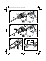
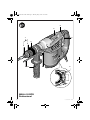
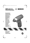
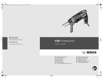
OBJ_BUCH-337-001.book Page 1 Monday, May 7, 2007 10:34 AM
GBH 4-32 DFR
Professional
Bedienungsanleitung
Operating instructions
Instructions d’emploi
Instrucciones de servicio
Manual de instruções
Istruzioni d’uso
Gebruiksaanwijzing
Betjeningsvejledning
Bruksanvisning
Brukerveiledningen
Käyttöohje
Οδηγία χειρισμού
Kullanım kılavuzu
Instrukcja obsługi
Návod k obsluze
Návod na používanie
Használati utasítás
Руководство по
эксплуатации
Інструкція з
експлуатації
Instrucţiuni de folosire
Ръководство за
експлоатация
Uputstvo za opsluživanje
Navodilo za uporabo
Upute za uporabu
Kasutusjuhend
Lietošanas pamācība
Naudojimo instrukcija
OBJ_BUCH-337-001.book Page 3 Monday, May 7, 2007 10:34 AM
A
x
B
C
3
1 619 929 774 • 7.5.07
OBJ_BUCH-337-001.book Page 4 Monday, May 7, 2007 10:34 AM
D
3
E
12
13 14
GRIP, ZU
RELEASE, AUF
F
9
G
X
15
4
16
17
18
19
20
1 619 929 774 • 7.5.07
OBJ_BUCH-337-001.book Page 5 Monday, May 7, 2007 10:34 AM
6
5
7
1
4
3
2
11 10
9
8
GBH 4-32 DFR
Professional
5
1 619 929 774 • 7.5.07
OBJ_BUCH-337-001.book Page 15 Monday, May 7, 2007 10:34 AM
d) Store idle power tools out of the reach of
children and do not allow persons unfamiliar with the power tool or these
instructions to operate the power tool.
Power tools are dangerous in the hands of
untrained users.
e) Maintain power tools. Check for misalignment or binding of moving parts, breakage of parts and any other condition that
may affect the power tool’s operation. If
damaged, have the power tool repaired
before use. Many accidents are caused by
poorly maintained power tools.
f) Keep cutting tools sharp and clean. Properly maintained cutting tools with sharp cutting
edges are less likely to bind and are easier to
control.
g) Use the power tool, accessories and tool
bits etc. in accordance with these instructions, taking into account the working
conditions and the work to be performed.
Use of the power tool for operations different
from those intended could result in a hazardous
situation.
5) Service
a) Have your power tool serviced by a qualified repair person using only identical
replacement parts. This will ensure that the
safety of the power tool is maintained.
f When working with the machine, always
hold it firmly with both hands and provide for
a secure stance. The power tool is guided more
secure with both hands.
f Secure the workpiece. A workpiece clamped
with clamping devices or in a vice is held more
secure than by hand.
f Do not work materials containing asbestos.
Asbestos is considered carcinogenic.
f Take protective measures when dust can
develop during working that is harmful to
one’s health, combustible or explosive.
Example: Some dusts are regarded as carcinogenic. Wear a dust mask and work with dust/chip
extraction when connectable.
f Keep your workplace clean. Blends of materials are particularly dangerous. Dust from light
alloys can burn or explode.
f Always wait until the machine has come to a
complete stop before placing it down. The
tool insert can jam and lead to loss of control over
the power tool.
f Never use the machine with a damaged
cable. Do not touch the damaged cable and
pull the mains plug when the cable is damaged while working. Damaged cables increase
the risk of an electric shock.
Functional Description
Machine-specific
Safety Warnings
f Wear hearing protection. Exposure to noise
can cause hearing loss.
f Always use the auxiliary handle supplied
with the machine. Loss of control can cause personal injury.
f Use suitable detectors to determine if utility
lines are hidden in the work area or call the
local utility company for assistance. Contact
with electric lines can lead to fire and electric
shock. Damaging a gas line can lead to explosion.
Penetrating a water line causes property damage
or may cause an electric shock.
f Hold the power tool only by the insulated
gripping surfaces when performing an operation where the cutting tool may contact hidden wiring or its own power cord. Contact with
a “live” wire will also make exposed metal parts of
the power tool “live” and shock the operator.
1 619 929 774 • 7.5.07
Read all safety warnings and all
instructions. Failure to follow the
warnings and instructions may result in
electric shock, fire and/or serious injury.
While reading the operating instructions, unfold the
graphics page for the machine and leave it open.
Intended Use
The machine is intended for hammer drilling in concrete, brick and stone, as well as for light chiselling
work. It is also suitable for drilling without impact in
wood, metal, ceramic and plastic. Machines with electronic control and right/left rotation are also suitable
for screwdriving and thread cutting.
Product Features
The numbering of the product features refers to the
illustration of the machine on the graphics page.
1 SDS-plus tool holder
2 Dust protection cap
3 Locking sleeve
English | 15
OBJ_BUCH-337-001.book Page 16 Monday, May 7, 2007 10:34 AM
4
5
6
7
8
9
10
11
12
13
14
15
16
17
18
19
20
Lock ring of the tool holder
Mode selector switch
Vibration damper
On/Off switch
Rotational direction switch
Button for depth stop adjustment
Auxiliary handle
Depth stop
Quick change keyless chuck*
Front sleeve of the quick change keyless chuck*
Retaining ring of the quick change
keyless chuck*
Extraction sleeve of the dust extraction
attachment*
Clamping screw for the dust extraction
attachment*
Depth stop of the dust extraction attachment*
Telescopic pipe of the dust
extraction attachment*
Wing bolt of the dust extraction attachment*
Guide pipe of the dust extraction attachment*
*The accessories illustrated or described are not
included as standard delivery.
Technical Data
Rotary Hammer
Article number
Rated power input
W
Rated speed
rpm
Impact rate
bpm
Impact energy per stroke
J
Chisel positions
Tool holder
Lubrication
Max. drilling dia.
– Concrete (with twist
drill)
– Brickwork (with core
bit)
– Steel
– Wood
Weight according to
EPTA-Procedure
01/2003
Protection class
GBH 4-32 DFR
Professional
3 611 C32 1..
900
0–760
0–3600
5.0
12
SDS-plus
Central permanent
lubrication
mm
32
mm
mm
mm
90
13
32
Noise/Vibration Information
Measured values
EN 60745.
determined
according
to
Typically the A-weighted noise levels of the product
are: Sound pressure level 93 dB(A); Sound power
level 104 dB(A). Uncertainty K =2 dB.
Wear hearing protection!
Vibration total values (triax vector sum) determined
according to EN 60745:
Hammer drilling into concrete: Vibration emission
value ah =8 m/s2, Uncertainty K=1,5 m/s2,
Chiselling: Vibration emission value ah =7 m/s2,
Uncertainty K=1,5 m/s2.
WARNING The vibration emission level given in
this information sheet has been
measured in accordance with a standardised test
given in EN 60745 and may be used to compare one
tool with another.
The vibration emission level will vary because of the
ways in which a power tool can be used and may
increase above the level given in this information
sheet. This could lead to a significant underestimate
of exposure when the tool is used regularly in such a
way.
Note: To be accurate, an estimation of the level of
exposure to vibration experienced during a given
period of work should also take into account the times
when the tool is switched off and when it is running
but not actually doing the job. This may significantly
reduce the exposure level over the total working
period.
Declaration of Conformity
We declare under our sole responsibility that this
product is in conformity with the following standards
or standardization documents: EN 60745 according
to the provisions of the directives 89/336/EEC,
98/37/EC.
Dr. Egbert Schneider
Senior Vice President
Engineering
Dr. Eckerhard Strötgen
Head of Product
Certification
05.04.2007, Robert Bosch GmbH, Power Tools Division
D-70745 Leinfelden-Echterdingen
kg
4.7
/II
The values given are valid for nominal voltages [U] of
230/240 V. For lower voltage and models for specific countries, these values can vary.
Please observe the article number on the type plate of your
machine. The trade names of the individual machines may
vary.
16 | English
1 619 929 774 • 7.5.07
OBJ_BUCH-337-001.book Page 17 Monday, May 7, 2007 10:34 AM
Assembly
f Before any work on the machine itself, pull
the mains plug.
Auxiliary Handle
f Operate your machine only with the auxiliary
handle 10.
The auxiliary handle 10 can be set to any position for
a secure and low-fatigue working posture.
Turn the bottom part of the auxiliary handle 10 in counterclockwise direction and swivel the auxiliary handle
10 to the desired position. Then retighten the bottom
part of the auxiliary handle 10 by turning in clockwise
direction.
Adjusting the Drilling Depth (see figure A)
The required drilling depth X can be set with the
depth stop 11.
Changing the Tool Holder
Dismounting the SDS-plus Tool Holder or the
Keyless Replacement Chuck (see figure B)
Pull the lock ring of the tool holder 4 firmly in the direction of the arrow, hold it in this position and pull off the
tool holder 1 or the keyless replacement chuck 12
toward the front.
After removing, protect the tool holder 1 or the keyless
replacement chuck 12 against contamination. Lightly
lubricate the engaging grooves, if required.
Mounting the SDS-plus Tool Holder or the Keyless Replacement Chuck
Grasp the tool holder 1 or the keyless replacement
chuck 12 completely with your hand. Slide the tool
holder 1 or the keyless replacement chuck 12 with a
turning motion onto the drill chuck mounting until a
distinct latching noice is heard.
Press the button for the depth stop adjustment 9 and
insert the depth stop into the auxiliary handle 10.
The tool holder 1 or the keyless replacement chuck 12
is automatically locked. Check the locking effect by
pulling the tool holder.
Insert the SDS-plus drilling tool to the stop into the
SDS-plus tool holder 1. Otherwise, the movability of
the SDS-plus drilling tool can lead to incorrect adjustment of the drilling depth.
Changing the Tool
Pull out the depth stop until the distance between the
tip of the drill bit and the tip of the depth stop correspond with the desired drilling depth X.
The knurled surface of the depth stop 11 must face
downward.
Selecting the Tool Holder
For hammer drilling, SDS-plus drilling tools that can
be inserted into the SDS-plus tool holder 1 are
required.
For drilling without impact in wood, metal, ceramic
and plastic as well as for screwdriving and tapping,
use non-SDS-plus drilling tools (e. g., drill bits with
cylindrical shank). A keyless drill chuck is required for
such drilling tools.
Note: Do not use tools without SDS-plus for hammer
drilling or chiselling! Tools without SDS-plus and their
drill chucks are damaged by hammer drilling or chiselling.
The SDS-plus tool holder 1 can easily be exchanged
against the quick change keyless chuck 12.
With the SDS-plus tool holder, simple and convenient
tool changing is possible without additional aids.
As a requirement of the system, the SDS-plus drilling
tool can move freely. This causes a certain radial runout at no-load, which has no effect on the accuracy of
the drill hole, as the drill bit centres itself upon drilling.
The dust protection cap 2 largely prevents the entry of
drilling dust into the tool holder during operation.
When inserting the tool, take care that the dust protection cap 2 is not damaged.
f A damaged dust protection cap should be
changed immediately. We recommend having this carried out by an after-sales service.
Inserting SDS-plus Drilling Tools (see figure C)
Clean and lightly grease the shank end of the tool.
Insert the tool in a twisting manner into the tool holder
until it latches itself.
Check the latching by pulling the tool.
Removing SDS-plus Drilling Tools
(see figure D)
Push back the locking sleeve 3 and remove the tool.
Inserting Drilling Tools without SDS-plus
(see figure E)
Note: Do not use tools without SDS-plus for hammer
drilling or chiselling! Tools without SDS-plus and their
drill chucks are damaged by hammer drilling or chiselling.
Insert the quick change keyless chuck 12.
1 619 929 774 • 7.5.07
English | 17
OBJ_BUCH-337-001.book Page 18 Monday, May 7, 2007 10:34 AM
Firmly hold the retaining ring of the keyless replacement chuck 12. Open the keyless replacement chuck
by turning the front sleeve in the direction of the symbol “
”.
Adjusting the Drilling Depth on the Dust Extraction Attachment (see figure G)
The required drilling depth X can also be adjusted
when the dust extraction attachment is mounted.
Insert the drilling tool into the keyless replacement
chuck 12. Firmly hold the retaining ring of the keyless
replacement chuck 12 and turn the front sleeve in the
direction of the symbol “
”.
Insert the SDS-plus drilling tool to the stop into the
SDS-plus tool holder 1. Otherwise, the movability of
the SDS-plus drilling tool can lead to incorrect adjustment of the drilling depth.
Check the tight seating by pulling the tool.
Loosen the wing bolt 19 on the dust extraction attachment.
Note: If the tool holder was opened to the stop, then
the latching noise possibly may be heard while closing
the tool holder and the tool holder will not close.
In this case, turn the front sleeve 13 once in the opposite direction of the arrow. Afterwards, the tool holder
can be closed (tightened) again.
Turn the mode selector switch 5 to the “drilling” position.
Removing Drilling Tools without SDS-plus
(see figure E)
Firmly hold the retaining ring of the keyless replacement chuck 12. Open the keyless replacement chuck
by turning the front sleeve in the direction of the symbol “
”.
Remove the drilling tool.
Dust Extraction with the Dust Extraction Attachment (Accessory)
Mounting the Dust Extraction Attachment
(see figure F)
For dust extraction, the dust extraction attachment
(accessory) is required. When drilling, the dust extraction attachment retracts so that the attachment head
is always close to the surface at the drill hole.
Press the button for depth stop adjustment 9 and
remove the depth stop 11. Press button 9 again and
insert the dust extraction attachment into the auxiliary
handle 10 from the front.
Connect an extraction hose (diameter 19 mm, accessory) to the extraction sleeve 15 of the dust extraction
attachment.
Without switching the power tool on, apply it firmly to
the drilling location. The SDS-plus drilling tool must
face against the surface.
Position the the guide pipe 20 of the dust extraction
attachment in its holding fixture in such a manner that
the head of the dust extraction attachment faces
against the surface to be drilled. Do not slide the
guide pipe 20 further over the telescopic pipe 18 of
the dust extraction attachment than required, so that
as much as possible of the scale 18 on the telescopic
pipe remains visible.
Retighten the wing bolt 19 again. Loosen the clamping screw 16 on the depth stop of the dust extraction
attachment.
Move the depth stop 17 on the telescopic pipe 18 in
such a manner that the clearance X shown in the figure corresponds with the required drilling depth.
Tighten the clamping screw 16 in this position.
Operation
Starting Operation
f Observe correct mains voltage! The voltage
of the power source must agree with the
voltage specified on the nameplate of the
machine. Power tools marked with 230 V can
also be operated with 220 V.
The vacuum cleaner must be suitable for the material
being worked.
Setting the Operating Mode
The operating mode of the power tool is selected with
the mode selector switch 5.
When vacuuming dry dust that is especially detrimental to health or carcinogenic, use a special vacuum
cleaner.
Note: Change the operating mode only when the
machine is switched off! Otherwise, the machine can
be damaged.
18 | English
1 619 929 774 • 7.5.07
OBJ_BUCH-337-001.book Page 19 Monday, May 7, 2007 10:34 AM
Turn the mode selector switch 5 to the requested
position.
Position for drilling without
impact in wood, metal,
ceramic and plastic as well as
for screwdriving and thread
cutting.
Position for hammer drilling
in concrete or stone
When the drilling tool does
not immediately rotate upon
switching on, allow the
machine to run slowly until the
drilling tool rotates.
Vario-Lock position for
adjustment of the chiselling
position
Overload Clutch
f If the tool insert becomes caught or jammed,
the drive to the drill spindle is interrupted.
Because of the forces that occur, always
hold the power tool firmly with both hands
and provide for a secure stance.
f If the power tool jams, switch the machine
off and loosen the tool insert. When switching the machine on with the drilling tool
jammed, high reaction torques can occur.
Changing the Chiselling Position (Vario-Lock)
The chisel can be locked in 12 positions. In this manner, the optimum working position can be set for each
application.
Insert the chisel into the tool holder.
Turn the mode selector switch 5 to the “Vario-Lock”
position (see “Setting the Operating Mode”,
page 18).
Turn the application tool to the requested chiselling
position.
Position for chiselling
Turn the mode selector switch 5 to the “chiselling”
position. The tool holder is now locked.
For chiselling, set the rotation direction to right rotation.
Reversing the Rotational Direction
Operating Instructions
f Actuate the rotational direction switch 8 only
when the machine is at a standstill.
Vibration Damper
The rotational direction switch 8 is used to reverse the
rotational direction of the machine.
Right rotation: Turn the rotational direction switch 8
to the stop in the position
.
Left rotation: Turn the rotational direction switch 8
to the stop in the position
.
Set the direction of rotation for hammer drilling, drilling
and chiselling always to right rotation.
Switching On and Off
To start the machine, press the On/Off switch 7 and
keep it depressed.
The integrated vibration damper reduces occurring
vibrations.
Maintenance and Service
Maintenance and Cleaning
To switch off the machine, release the On/Off switch
7.
f Before any work on the machine itself, pull
the mains plug.
For low temperatures, the power tool reaches the full
hammer/impact capacity only after a certain time.
f For safe and proper working, always keep
the machine and ventilation slots clean.
Setting the Speed/Impact Rate
The speed/impact rate of the switched on power tool
can be variably adjusted, depending on how far the
On/Off switch 7 is pressed.
Light pressure on the On/Off switch 7 results in low
speed/impact rate. Further pressure on the switch
increases the speed/impact rate.
1 619 929 774 • 7.5.07
f A damaged dust protection cap should be
changed immediately. We recommend having this carried out by an after-sales service.
If the machine should fail despite the care taken in
manufacturing and testing procedures, repair should
be carried out by an after-sales service centre for
Bosch power tools.
English | 19
OBJ_BUCH-337-001.book Page 20 Monday, May 7, 2007 10:34 AM
In all correspondence and spare parts order, please
always include the 10-digit article number given on
the type plate of the machine.
Disposal
WARNING! Important instructions for connecting a new 3-pin plug to the 2-wire cable.
The wires in the cable are coloured according to the
following code:
Only for EC countries:
Do not connect the blue or brown wire to the earth
terminal of the plug.
Important: If for any reason the moulded plug is
removed from the cable of this power tool, it must be
disposed of safely.
The machine, accessories and packaging should be
sorted for environmental-friendly recycling.
Do not dispose of power tools into
household waste!
According the European Guideline
2002/96/EC for Waste Electrical and
Electronic Equipment and its implementation into national right, power
tools that are no longer usable must be collected separately and disposed of in an environmentally correct
manner.
Subject to change without notice.
Service and Customer Assistance
Exploded views and information on spare parts can be
found under:
www.bosch-pt.com
Great Britain
Robert Bosch Ltd. (B.S.C.)
P.O. Box 98
Broadwater Park
North Orbital Road
Denham-Uxbridge
Middlesex UB 9 5HJ
✆ Service: . . . . . . . . . . . . . +44 (0) 18 95 / 83 87 82
✆ Advice line:. . . . . . . . . . . +44 (0) 18 95 / 83 87 91
Fax: . . . . . . . . . . . . . . . . . . . +44 (0) 18 95 / 83 87 89
Ireland
Origo Ltd.
Unit 23 Magna Drive
Magna Business Park
City West
Dublin 24
✆ Service: . . . . . . . . . . . . . . .+353 (0)1 / 4 66 67 00
Fax: . . . . . . . . . . . . . . . . . . . . .+353 (0)1 / 4 66 68 88
Australia and New Zealand
Robert Bosch Australia Pty. Ltd.
RBAU/SPT
1555 Centre Road
P.O. Box 66
3168 Clayton/Victoria
✆ . . . . . . . . . . . . . . . . . . . . +61 (0)1 / 3 00 30 70 44
Fax: . . . . . . . . . . . . . . . . . . . +61 (0)1 / 3 00 30 70 45
www.bosch.com.au
20 | English
1 619 929 774 • 7.5.07