1
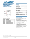
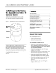
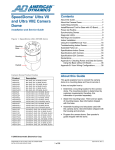
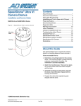
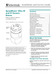
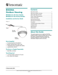
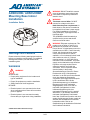
WARNING! DO NOT install this camera
dome in hazardous areas where highly
combustible or explosive products are
stored or used.
ADSDUIOB / ADSDUIOBW
Mounting Base Indoor
Installation
WARNING!
This dome runs on 24Vac. DO NOT
connect line voltage to this dome.
Installation Guide
North America power requirements: In
North America, this device is intended to
be supplied from a Class 2 power supply.
For outdoor installations, use Class 3
wiring techniques, liquid-tight conduit, or
liquid-tight pipe.
This installation should be made by a
qualified service person and should
conform to all local codes.
WARNING! EU power requirements: This
product runs on 24Vac. In the EU, it is
intended to be powered from a Limited
Power Source. A limited power source is a
certified source of SELV, and if inherently
limited, with 8 amps maximum output
current, and a maximum of 100VA
available; or if not inherently limited, fused
with a maximum value of 3.3 Amps,
meeting section 2.11 of IEC950, and a
maximum of 250VA available. The power
supply can be obtained through American
Dynamics or through another source
where the provider can furnish the
verification. This is required to assure
electrical safety in the product.
Warnings and Cautions
Please review the following warnings and cautions
before you install the mounting base. For additional
warnings and cautions, see the camera dome
installation guide.
WARNINGS
WARNING!
Stromanforderungen in der EU: Dieses
Produkt wird mit 24 V Wechselstrom
betrieben. In der EU ist es für den Betrieb
durch eine begrenzte Stromquelle
vorgesehen. Eine begrenzte Stromquelle
ist eine zertifizierte SELV-Quelle
(Schutzkleinspannung), bei inhärenter
Begrenzung mit einem maximalen
Ausgangsstrom von 8 A und 100 VA
maximaler Verfügbarkeit, bei nicht
inhärenter Begrenzung mit einer
maximalen Sicherung von 3,3 A gemäß
Abschnitt 2.11 der IEC950 und 250 VA
maximaler Verfügbarkeit. Das Netzteil
kann über S American Dynamics oder eine
andere Quelle bezogen werden, wobei der
Anbieter den Nachweis der Konformität
bereitstellen sollte. Dies ist zur
Gewährleistung der elektrischen Sicherheit
des Produktes erforderlich.
ALWAYS USE:
• Proper safety equipment for the location and
type of installation.
• Proper lift equipment to reach the installation.
• Safety features of the lift equipment.
BE SURE:
• Electrical power is not connected to the dome
when connecting wires. Dome will move when
power is applied.
• Electrical power is not connected to nearby
fixtures that you might touch during installation.
© 2006 Sensormatic Electronics Corp.
ADSDU8IOB / ADSDU8IOBW MOUNTING BASE
INSTALLATION GUIDE
8200-0600-04, REV. A
1 of 6
Cautions
Before You Begin
• The maximum length of power cable allowed
between the Class 2 LPS (low voltage) ac
source, such as a J-box, and the dome is 250m
(820ft).
Please read the following to ensure a smooth and
successful installation.
You must:
• Have electrical work comply with latest national
electrical code, national fire code, and all
applicable local codes and ordinances.
• Do not run data and power cables adjacent to or
in the same conduit as line voltage mains
power.
• Coordinate work with other trades to avoid
interference.
• SensorNet 485 networks require 22 AWG
unshielded cable. Do not exceed 32 devices per
cable run.
• Verify existing site conditions and coordinate
with the owner’s representative and appropriate
utilities as required.
• RS-422 networks require 22 AWG shielded
cable. Do not exceed 10 devices per cable run.
• Obtain copies of all related plans, specifications,
shop drawings and addenda to schedule and
coordinate related work.
• Manchester networks require 18AWG shielded
cable. Do not exceed three devices per cable
run.
• Thoroughly review the project to ensure that all
work meets or exceeds the above requirements.
Bring alleged to the attention of the CCTV
Project Coordinator.
• Always terminate the camera dome connected
at the end of a cable run.
• The I/O board is electrostatic-sensitive! Use a
ground strap when handling the I/O board.
• The spring finger connector on the I/O board
has a dust cover. DO NOT remove this cover
until you have installed the dome’s base. It
protects delicate spring fingers. Keep the dust
cover for use should you have to ship the
mounting base back to the manufacturer.
Tools Required
• Phillips screwdriver
• Power drill with 3.2mm (1/8in), 6.4mm (1/4in),
9.5mm (3/8in), and 19.5mm (3/4in) drill bits
• Hammer
• Screw terminal connectors on the I/O board are
delicate! Use a jeweler’s 2.5mm (0.1in) slotted
screwdriver to tighten connector screws. DO
NOT over tighten these screws.
• Socket wrench with 152mm (6in) extension, and
5.5mm and 10mm sockets
• Jeweler’s 2.5mm (0.1in) slotted screwdriver (for
wire connections)
• 18-14AWG and 22-20AWG wire strippers
Installation
• Vacuum and broom.
This section explains how to attach the base and
wire the I/O board. Once done, refer to installation
and service Guide for the dome camera for further
instructions. Perform procedures in the following
order:
Parts Required
Item
Base with I/O Board
Install Kit
Anchor, Toggle
Screw, STAP, 4.2x32 PH
Washer, Flat, M4
Nut, Locking, M3
1. Detach the I/O board from the base (page 3).
2. Attach the base indoors to a:
• Tile ceiling (page 3)
• Hard ceiling (page 3)
• Mounting structure (page 4).
3. Wire the I/O board (page 4).
4. Reattach the I/O board (page 6).
ADSDU8IOB / ADSDU8IOBW MOUNTING BASE
INSTALLATION GUIDE
Qty
1
1
2
2
2
2
Part Number
0101-0175-01/02
0352-0324-01
2880-0073-01
5810-4091-120
5842-0300-020
5826-0200-020
8200-0600-04, REV. A
2 of 6
Detaching the I/O Board
Attaching to a Tile Ceiling
To attach the mounting base, you must first
remove the I/O board. To do this, push the fingers
molded into the base away from the board while
pushing on the I/O board with your index finger
(Figure 1). Put the board in a safe place; you will
use it when you attach the dome.
Requires RHIUTBAR T-bar kit (optional).
Attaching to a Hard Ceiling
To attach the base to a hard ceiling, do the
following (Figure 2):
CAUTION: The spring finger connector
on the I/O board has a dust cover. DO
NOT remove this cover until you have
installed the dome’s base. It protects
delicate spring fingers. Keep the dust
cover for use should you have to ship the
mounting base back to the manufacturer.
1. Mark and drill holes.
Place the base against the ceiling and mark and
drill holes for two mounting screws. If mounting
to sheet rock, also mark and drill a hole for
cable access.
SHEET ROCK: Drill two 9.5mm (3/8in) holes for
plastic anchors. Drill one 19.5mm (3/4in) hole
for cable access.
CAUTION: Use a ground strap when
handling the I/O board.
WOOD: Drill two 3.2mm (1/8in) holes for
mounting screws. If wood covers the cable
access hole, drill one 19.5mm (3/4in) hole for
cable access.
Figure 1. Detaching the I/O board
2. Attach the base to the ceiling.
SHEET ROCK: Install the plastic anchors. Then
place the washers onto the screws and insert
them into the anchors.
Mounting Base
a
WOOD: Place the washers onto the screws and
insert them into the wood.
3. Feed the cables through the access hole and go
to “Wiring the I/O Board,” page 4.
Figure 2. Surface mounting to sheet rock and
wood beams
I/O board
Screw (2)
Anchor (2)
ADSDU8IOB / ADSDU8IOBW MOUNTING BASE
INSTALLATION GUIDE
8200-0600-04, REV. A
3 of 6
Attaching to a Mounting Structure
Wiring the I/O Board
To attach the base to a mounting structure:
CAUTION: The maximum length of
cable allowed between the Class 2 LPS
(low voltage) ac source, such as a J-box,
and the dome is 250m (820ft).
1. Attach the base to the structure using the two
nuts supplied with the structure (Figure 3).
2. Feed the cables through the access hole.
This procedure explains how to connect the cables
to the I/O board, check the cable connections, and
attach the I/O board to the dome’s base. Once
done, attach the housing and eyeball assembly to
the base (refer to the instructions included with the
housing and eyeball assembly).
3. Go to “Wiring the I/O Board,” page 4.
Figure 3. Attaching the base to a mounting
structure
WARNING: Ensure that ac power and
electrical signals are off during wire
connections!
!
Referring to Figure 4:
1. Set the termination jumper JW1 according to the
dome’s position in the communications line.
Position of dome in
communications line…
Between other devices
End of communications line
Use M3 nuts from
mounting structure
RHIULWM or RHIUPND
Setting
Unterminated
Terminated
Pins
Off
1-2
Note: You may need a small slotted screwdriver
to gently pry jumper loose. Be careful not to
damage the PC board.
Use M3 nuts from
mounting structure
RHIUWM
2. Connect the video cable to the I/O board BNC
video cable extension.
3. Connect the Manchester, RS-422, or SensorNet
485 data wires to connector TB1. If using a
Pelco Coaxitron or Panasonic UTC protocol, no
data wires are connected, just power.
Manchester data connections.
Order data cable 88760 (plenum) or 8760 (nonplenum) from Belden by calling 1-800-235-3361.
Use M3 nuts from
mounting structure
RHIUCM
Pin
Color
Designation
1-4
—
5
Black
Manchester (+)
Not used.
6
White
Manchester (–)
RS-422 data connections
ADSDU8IOB / ADSDU8IOBW MOUNTING BASE
INSTALLATION GUIDE
Pin
Color
1
Orange
Designation
RS-422 Data In High (+)
2
Green
RS-422 Data In Low (–)
3
Yellow
RS-422 Data Out High (+)
4
Brown
RS-422 Data Out Low (–)
5-6
—
Not used.
8200-0600-04, REV. A
4 of 6
5. Connect the alarm output cable, if used, to the
TB2 connector.
SensorNet data connections
Pin
Color
Designation
1-4
—
Pin
Color
5
Orange
SensorNet (unshielded)
1
—
6
Yellow
SensorNet (unshielded)
2
—
12Vdc (100mA max.)
3
—
Output 1 (40mA sync. max.)
4
—
Output 2 (40mA sync. max.)
5
—
Output 3 (40mA sync. max.)
6
—
Ground
Not used.
4. Connect twisted pair wires, if used, to connector
TB5.
Pin
Designation
1
Video
2
Video Ground
Designation
12Vdc (100mA max.)
6. Connect the alarm input cable, if used, to the
TB3 connector.
Figure 4. Electrical connections
Pin
Color
1
—
Designation
Alarm 1 input (3.5mA sink)
2
—
Alarm 2 input (3.5mA sink)
3
—
Alarm 3 input (3.5mA sink)
4
—
Alarm 4 input (3.5mA sink)
5
—
Ground
6
—
Ground
7. Connect power to the TB4 connector.
Video
Twisted
Pair
RS-422 Data,
SensorNet Data,
Manchester Data
Pin
Color
Designation
1
Black
24Vac
2
Red
Ground
3
White
24Vac
8. Reattach the I/O board.
9. Connect power to the base.
Video
BNC
Alarm
Inputs
Alarm
Outputs
Power
ADSDU8IOB / ADSDU8IOBW MOUNTING BASE
INSTALLATION GUIDE
Termination
Jumper
8200-0600-04, REV. A
5 of 6
10. Check the LEDs on the I/O board to verify
power and data are reaching the dome
(Figure 5).
a. The green ac power LED (CR9) glows
steadily when ac power is applied.
b. For Manchester or SensorNet: The yellow
comm. LED (CR11) glows steadily
(Manchester) or blinks (SensorNet). If this
LED is off, then probably one or both
communication wires are open or both are
shorted together.
For RS-422: Press and hold data test switch
SW1 and observe nearby red (CR12) and
green (CR13) LEDs; they indicate the
following:
Constant green,
Blinking red
RS-422 line correctly wired.
Constant green,
Red off
RS-422 "Data In –" shorted to
ac ground.
Constant red,
Blinking green
"Data In +/ –" wires reversed.
Blinking red,
Green off
"Data In +" shorted to ac
ground.
Both LEDs off
"Data In +/ –" wires shorted or
open.
Reattaching the I/O Board
The following procedure refers to Figure 6:
1. If the wiring is OK, then pull the excess cable up
through the access hole.
2. Reinsert the I/O board.
Insert the board under the retaining fingers. The
board is keyed; it only fits into the base one
way. Press on the board to snap it into place.
3. Gently remove the dust cover.
Remove the cover from the 32-pin connector
and inspect the spring finger contacts. For
reliable connections, all contacts should be at
least 2mm above the surface of the connector.
CAUTION: Keep the dust cover for
use should you have to ship the base
and I/O board back to the
manufacturer.
Figure 6. Reattaching the I/O board
Figure 5. Test switch/LEDs on I/O board
Yellow
(CR11)
Red
(CR12)
Green
(CR13)
Green
(CR9)
SW1
ADSDU8IOB / ADSDU8IOBW MOUNTING BASE
INSTALLATION GUIDE
8200-0600-04, REV. A
6 of 6