1
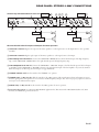
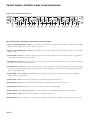
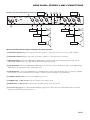
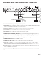
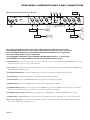
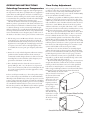
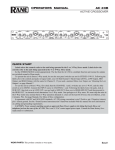
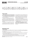
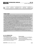
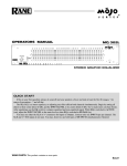
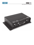
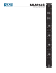
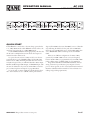
OPERATORS MANUAL
AC 23S
ACTIVE CROSSOVER
LOW
CH 1
4
LEVEL
6
2
4
8
0
LOW / MID
2W: INACTIVE
MASTER
LEVEL
10
MONO MASTER
6
2
8
0
10
DELAY
MUTE
4
6
2
8
MIN
MAX
SUBWOOFER
MID
2W: INACTIVE
2W: LOW
FREQUENCY
LEVEL
DELAY
240
400
MUTE
200
600
4
6
4
6
150
750
100
850
80
900 2
8
2
8
70
1k
0
SUB / LOW
10
MIN
MID
MID / HIGH
2W: LOW / HIGH
FREQUENCY
700
1.0k
550
2.0k
475
2.8k
350
4.5k
250
5.8k
190
7.0k
MAX
HIGH
CH 2
LEVEL
MASTER
LEVEL
4
2
4
8
0
4W: MID / HIGH
5W: MID / HIGH-MID
6
10
LOW
6
2
4
8
0
10
MONO 4W OR 5W: INACTIVE
LOW / MID
2W: INACTIVE
LEVEL
6
2
8
0
DELAY
MUTE
4
2
10
8
MIN
LOW
6
MID
2W: INACTIVE
2W: LOW
FREQUENCY
LEVEL
DELAY
240
400
MUTE
200
600
4
6
4
6
150
750
100
850
80
900 2
8
2
8
70
1k
MAX
0
LOW / MID
10
MIN
4W: INACTIVE
5W: HIGH-MID
MID / HIGH
2W: LOW / HIGH
FREQUENCY
700
1.0k
550
2.0k
475
2.8k
350
4.5k
250
5.8k
190
7.0k
MAX
HIGH
LEVEL
4
AC 23S
ACTIVE
CROSSOVER
8
0
4W: INACTIVE
5W: HIGH-MID / HIGH
6
2
10
HIGH
POWER
QUICK START
Labels above the controls refer to the unit being operated in the
2- or 3-Way Stereo mode. Labels below the controls refer to the
unit being operated in the 4- or 5-Way Mono mode.
Set the STEREO/MONO switch appropriately. The fact that
the AC 23S is a multiple function unit means the outputs are
switched around in Mono mode.
To operate the unit in Stereo 3-Way mode, be sure the rear
panel switches are set for STEREO 3-Way, and the 4W / 5W
switch is set for 5-Way. Following the labels above the controls
and jacks in logical order, you will find Channel 1 Master Input
LEVEL, LOW Output, MID Output, and HIGH Output, with
the same for Channel 2. If you need a summed Mono Low Ouput, see ‘Monoing the Low Outputs’ on page Manual-15.
To use the unit as a Mono 5‑Way, first check that the Channel 1 and 2 switches are set to 3-WAY, and the push-switch is
WEAR PARTS: This product contains no wear parts.
depressed for MONO. Connect the INPUT source to Channel 1
only. Following the labels below the jacks, look at SUB OUT,
then look over at LOW OUT, now go back to MID OUT, then
over to HIGH-MID OUT and then proceed to the HIGH
OUT.
There are two different configurations for Mono 4-Way
systems. If your LOW / MID can use a crossover frequency
between 70 Hz-1 kHz, see page Manual-7. If your LOW / MID
prefers a higher range of 190 Hz-7 kHz, see page Manual-8.
In agreement with IEC and AES/ANSI standards, AC 23S
wiring convention is pin 2 Positive, pin 3 Negative (return),
pin 1 to chassis ground. See the “Sound System Interconnection”
RaneNote included with this manual for more information on
cabling and grounding requirements.
Manual-1
FRONT PANEL: STEREO 2-WAY CONFIGURATION
Stereo 2-way control labels are in this row
LOW
CH 1
4
LEVEL
6
2
4
8
0
10
MONO MASTER
1
LOW / MID
2W: INACTIVE
MASTER
LEVEL
6
2
8
0
10
DELAY
MUTE
4
6
2
8
MIN
MAX
SUBWOOFER
MID
2W: INACTIVE
2W: LOW
FREQUENCY
LEVEL
DELAY
240
400
MUTE
200
600
4
6
4
6
150
750
100
850
80
900 2
8
2
8
70
1k
0
SUB / LOW
�
10
MIN
MID / HIGH
2W: LOW / HIGH
FREQUENCY
700
1.0k
550
2.0k
475
2.8k
350
4.5k
250
5.8k
190
7.0k
MAX
MID
345
HIGH
CH 2
LEVEL
MASTER
LEVEL
4
2
4
8
0
4W: MID / HIGH
5W: MID / HIGH-MID
6
6
2
10
LOW
4
8
0
10
MONO 4W OR 5W: INACTIVE
6 7 2
LOW / MID
2W: INACTIVE
LEVEL
6
2
8
0
DELAY
MUTE
4
6
2
10
8
MIN
MAX
LOW
MID
2W: INACTIVE
2W: LOW
FREQUENCY
LEVEL
DELAY
240
400
MUTE
200
600
4
6
4
6
150
750
100
850
80
900 2
8
2
8
70
1k
0
LOW / MID
�
10
MIN
MID / HIGH
2W: LOW / HIGH
FREQUENCY
700
1.0k
550
2.0k
475
2.8k
350
4.5k
250
5.8k
190
7.0k
MAX
HIGH
LEVEL
4
4W: INACTIVE
5W: HIGH-MID / HIGH
345
6
AC 23S
ACTIVE
CROSSOVER
8
0
4W: INACTIVE
5W: HIGH-MID
6
2
10
HIGH
POWER
78
Observe the labels above the controls for stereo operation.
*Not used for 2‑channel 2‑way
1 Channel 1 MASTER LEVEL control: Sets the overall Level of Channel 1 without altering the relative settings of the Low and
High frequency Outputs. Unity gain for all level controls is at “7”.
2 Channel 2 MASTER LEVEL control: Sets the overall Level of Channel 2 without altering the relative settings of the Low and
High Outputs.
3 LOW LEVEL control: Sets the Level of signal going to the Low Frequency output in this channel. Refer to ‘Setting the Output
Level Controls’ on page Manual-13.
4 LOW MUTE switch: When pressed to the in position, all signal is removed from the Low Frequency Output. This eases tune‑up
procedures as described on pages Manual-9-14.
5 LOW DELAY control: Adds from 0 to 2 ms of time Delay to the Low Frequency Output only. This allows a low frequency driver
to be electronically phase‑aligned with a mid frequency driver whose diaphragm is situated behind the low frequency diaphragm.
Refer to ‘Time Delay Adjustment’ on pages Manual-9-12.
6 LOW / HIGH crossover frequency selector: This 41‑detent selector sets the crossover frequency between the Low and High
frequency Outputs. Refer to ‘Selecting Crossover Frequencies’ on page Manual-9.
7 HIGH LEVEL control: Sets the Level of signal going to the High frequency Output only.
8 POWER indicator: Two guesses. When this yellow LED is lit, you guessed right — the unit is on and ready.
Manual-2
REAR PANEL: STEREO 2-WAY CONNECTIONS
Stereo 2-way connection labels are in this row
AC 23S
100-240 V
50/60 Hz 7 WATTS
COMMERCIAL AUDIO
EQUIPMENT 24TJ
MADE IN U.S.A.
RANE CORP.
HIGH OUT
PIN 2: POSITIVE
PIN 3: NEGATIVE
PIN 1: CHASSIS GND
Right Input
3W: MID OUT
2W: LOW
3W: LOW OUT
2W: OMIT
2
6 57 6
CHANNEL 2 IN
STEREO 3W / 2W
Left Input
HIGH OUT
3W: MID OUT
2W: LOW
MONO: OMIT
MID OUT
3
4
3W: LOW OUT
2W: OMIT
1
CHANNEL 1 IN
SET TO
5W
R
CHANNEL 2
STEREO
3W
2W
ACN 001 345 482
This device complies with Part 15 of the FCC Rules. Operation is
subject to the following two conditions: (1) this device may not cause
harmful interference, and (2) this device must accept any interference
received, including interference that may cause undesired operation.
8
4W: OMIT
HIGH OUT
5W: HIGH MID OUT
3
4
LOW OUT
MONO: OMIT
STEREO
MONO
4W
5W
CHANNEL 1
STEREO
3W
2W
MONO: SET SWITCHES AS SHOWN
High Amp
Low Amp
SUB OUT
MONO 4W / 5W IN
High Amp
Low Amp
Observe the labels above the Inputs and Outputs for Stereo operation.
1 CHANNEL 1 INPUT: Plug the left output of the mixer, equalizer or other signal source to this Input. Pin 2 is “hot” per AES
standards.
2 CHANNEL 2 INPUT: Plug the right output of the mixer, equalizer or other signal source to this Input.
3 HIGH FREQUENCY OUTPUTS: Connect the CHANNEL 1 HIGH OUT to the left channel input of the high frequency
amp, and the CHANNEL 2 HIGH OUT to the right channel input of the high frequency amp.
4 LOW FREQUENCY OUTPUTS: Connect the CHANNEL 1 “2W-LOW” Output to the left channel input of the low frequency amplifier, and the CHANNEL 2 “2W-LOW” Output to the right channel input of the low amplifier. If you need a summed
Mono Low Ouput, see ‘Monoing the Low Outputs’ on page Manual-15.
5 STEREO / MONO switch: Set this switch to the STEREO “out” position.
6 STEREO 2‑Way / 3‑Way switches: Slide the switches to the 2‑Way position. This switch removes the Low frequency crossover
from the signal path. Low frequencies are now routed to the Mid frequency Output. Note: The Low frequency outputs are still active
and may be used as additional Low outputs.
7 MONO 4-Way / 5-Way switch: Set this switch to the 5-Way position for stereo operation.
8 Universal Voltage Input: via a miniature IEC 60320 C6 appliance inlet. This mates with an IEC 60320 C5 line cord (USA
domestic). Do not lift the ground connection!
Manual-3
FRONT PANEL: STEREO 3-WAY CONFIGURATION
Stereo 3-way control labels are in this row
LOW
CH 1
4
LEVEL
6
2
4
8
0
LOW / MID
2W: INACTIVE
MASTER
LEVEL
10
MONO MASTER
6
2
8
0
10
DELAY
MUTE
4
6
2
8
MIN
MAX
SUBWOOFER
1 345
MID
2W: INACTIVE
2W: LOW
FREQUENCY
LEVEL
DELAY
240
400
MUTE
200
600
4
6
4
6
150
750
100
850
80
900 2
8
2
8
70
1k
0
SUB / LOW
10
MIN
MID / HIGH
2W: LOW / HIGH
FREQUENCY
700
1.0k
550
2.0k
475
2.8k
350
4.5k
250
5.8k
190
7.0k
MAX
MID
6 789
HIGH
CH 2
LEVEL
MASTER
LEVEL
4
2
0
4
8
0
4W: MID / HIGH
5W: MID / HIGH-MID
6
10
LOW
6
2
4
8
0
10
LOW / MID
2W: INACTIVE
LEVEL
6
2
8
0
DELAY
MUTE
6
2
10
MONO 4W OR 5W: INACTIVE
4
8
MIN
MAX
LOW
q 2 345
MID
2W: INACTIVE
2W: LOW
FREQUENCY
LEVEL
DELAY
240
400
MUTE
200
600
4
6
4
6
150
750
100
850
80
900 2
8
2
8
70
1k
0
LOW / MID
10
MIN
MID / HIGH
2W: LOW / HIGH
FREQUENCY
700
1.0k
550
2.0k
475
2.8k
350
4.5k
250
5.8k
190
7.0k
MAX
4W: INACTIVE
5W: HIGH-MID
HIGH
LEVEL
4
6 789
0
AC 23S
ACTIVE
CROSSOVER
8
0
4W: INACTIVE
5W: HIGH-MID / HIGH
6
2
10
HIGH
POWER
qw
Observe the labels screened above the controls for stereo operation.
1 Channel 1 MASTER LEVEL control: Sets the overall Level of Channel 1 without altering the relative settings of the Low/Mid/
High frequency Outputs. Unity gain for all Level controls is at “7”.
2 Channel 2 MASTER LEVEL control: Sets the overall Level of Channel 2 without altering the relative settings of the Low/Mid/
High Outputs.
3 LOW LEVEL control: Sets the Level of signal going to the Low frequency Output only in this Channel. Refer to page Manual13 for guidance with the Level control settings.
4 LOW MUTE switch: When pressed to the in position, all signal is removed from the Low frequency Output. This eases tune‑up
procedures as described on pages Manual-9-14.
5 LOW DELAY control: Adds from 0 to 2 ms of time delay to the Low Frequency Output only. This allows a low frequency driver
to be electronically phase‑aligned with a mid frequency driver whose diaphragm is situated behind the low frequency diaphragm.
Refer to pages Manual-9-12.
6 LOW / MID crossover frequency selector: This 41‑detent selector sets the crossover frequency between the Low and Mid
Outputs. Refer to page Manual-9.
7 MID LEVEL control: Sets the Level of signal going to the Mid Output in this Channel only.
8 MID MUTE switch: Removes all signal from the Mid Frequency Output when pressed to the in position.
9 MID DELAY control: Adds from 0 to 2 ms of time Delay to this Channel’s Mid Output.
0 MID / HIGH crossover frequency selector: Sets the frequency between the Mid and High Outputs in this Channel.
q HIGH LEVEL control: Sets the Level of signal going to the High Output only.
w POWER indicator: Two choices: on or off. If the power is plugged in and this yellow LED is lit, then the unit ready to operate.
Manual-4
REAR PANEL: STEREO 3-WAY CONNECTIONS
Stereo 3-way connection labels are in this row
AC 23S
100-240 V
50/60 Hz 7 WATTS
COMMERCIAL AUDIO
EQUIPMENT 24TJ
MADE IN U.S.A.
RANE CORP.
HIGH OUT
PIN 2: POSITIVE
PIN 3: NEGATIVE
PIN 1: CHASSIS GND
Right Input
3W: MID OUT
2W: LOW
3W: LOW OUT
2W: OMIT
2
CHANNEL 2 IN
7 68 7
STEREO 3W / 2W
Left Input
3W: LOW OUT
HIGH OUT
3W: MID OUT
2W: LOW
MONO: OMIT
MID OUT
SUB OUT
3
4
5
2W: OMIT
1
CHANNEL 1 IN
SET TO
5W
R
CHANNEL 2
STEREO
3W
2W
ACN 001 345 482
This device complies with Part 15 of the FCC Rules. Operation is
subject to the following two conditions: (1) this device may not cause
harmful interference, and (2) this device must accept any interference
received, including interference that may cause undesired operation.
9
4W: OMIT
HIGH OUT
5W: HIGH MID OUT
LOW OUT
3
4
5
MONO: OMIT
STEREO
MONO
4W
5W
CHANNEL 1
STEREO
3W
2W
MONO: SET SWITCHES AS SHOWN
High Amp
MONO 4W / 5W IN
High Amp
Mid Amp
Mid Amp
Low Amp
Low Amp
Observe the labels above the Inputs and Outputs for Stereo operation.
1 CHANNEL 1 INPUT: Plug the left output of the mixer, equalizer or other source here. Pin 2 is “hot” per AES standards.
2 CHANNEL 2 INPUT: Plug the right output of the mixer, equalizer or other signal source to this Input.
3 HIGH OUTPUTS: Connect the CHANNEL 1 HIGH OUT to the left channel input of the high frequency amp, and the
CHANNEL 2 HIGH OUT to the right channel input of the high frequency amp.
4 MID OUTPUTS: Connect the CHANNEL 1 MID OUT to the left channel of the mid frequency amp, and the CHANNEL 2
MID OUT to the right channel of the mid frequency amp.
5 LOW OUTPUTS: Connect the CHANNEL 1 and 2 LOW OUTS to the left and right channels of the low frequency amplifier,
respectively. If you need a summed Mono Low Ouput, see ‘Monoing the Low Outputs’ on page Manual-15.
6 STEREO / MONO switch: Set this to the STEREO (out) position.
7 STEREO 2‑Way / 3‑Way switches: Set both Channels to the 3‑Way position.
8 MONO 4-Way / 5-Way switch: Set this switch to the 5-Way position for stereo operation.
9 Universal Voltage Input: via a miniature IEC 60320 C6 appliance inlet. This mates with an IEC 60320 C5 line cord (USA
domestic). Do not lift the ground connection!
Manual-5
FRONT PANEL: MONO 4-WAY AND 5-WAY CONFIGURATION
Mono 4-way and 5-way control labels are in these rows
LOW
CH 1
4
LEVEL
6
2
4
8
0
LOW / MID
2W: INACTIVE
MASTER
LEVEL
10
MONO MASTER
6
2
8
0
10
DELAY
MUTE
4
6
2
8
MIN
MAX
SUBWOOFER
1 234
MID
2W: INACTIVE
2W: LOW
FREQUENCY
LEVEL
DELAY
240
400
MUTE
200
600
4
6
4
6
150
750
100
850
80
900 2
8
2
8
70
1k
0
SUB / LOW
10
MIN
MID / HIGH
2W: LOW / HIGH
FREQUENCY
700
1.0k
550
2.0k
475
2.8k
350
4.5k
250
5.8k
190
7.0k
MAX
MID
5 0qw
HIGH
CH 2
LEVEL
MASTER
LEVEL
4
6
4
2
8
0
6
2
10
LOW
4
8
0
10
4W: MID / HIGH
5W: MID / HIGH-MID
MONO 4W OR 5W: INACTIVE
e
�
LOW / MID
2W: INACTIVE
LEVEL
6
2
8
0
DELAY
MUTE
4
6
2
10
8
MIN
MID
2W: INACTIVE
2W: LOW
FREQUENCY
LEVEL
DELAY
240
400
MUTE
200
600
4
6
4
6
150
750
100
850
80
900 2
8
2
8
70
1k
MAX
LOW
678
0
LOW / MID
10
MIN
MID / HIGH
2W: LOW / HIGH
FREQUENCY
700
1.0k
550
2.0k
475
2.8k
350
4.5k
250
5.8k
190
7.0k
MAX
4W: INACTIVE
5W: HIGH-MID
9 rty
HIGH
LEVEL
4
u
AC 23S
ACTIVE
CROSSOVER
8
0
4W: INACTIVE
5W: HIGH-MID / HIGH
6
2
10
HIGH
POWER
io
Observe the labels screened below the controls for Mono operation.
1 MASTER LEVEL control: Sets the overall Level of the entire unit in Mono mode, without changing relative settings of the
individual Sub/Low/Mid/High Outputs. Unity gain for all Level controls is “7”.
2 SUBWOOFER LEVEL control: Sets the Level of signal going to the Sub Output. See page Manual-13.
3 SUBWOOFER MUTE switch: Removes all signal from the Sub Output when pressed to the in position. This eases the system
tune‑up procedure, as described on pages Manual-9-14.
4 SUBWOOFER DELAY control: In Subwoofer applications this control has virtually no effect and will normally be set to MIN
(minimum). Refer to pages Manual-9-12 for alignment procedures.
5 SUB / LOW crossover frequency selector: This 41‑detent selector sets the crossover frequency between the Subwoofer and Low
Outputs. Refer to page Manual-9 to determine the proper setting for your system.
6 LOW LEVEL control: Sets the Level going to the Low frequency Output.
7 LOW MUTE switch: Removes all signal from the Low Output when pressed in.
8 LOW DELAY control: Adds from 0 to 2 ms of time Delay to the Low Output only.
9 LOW / MID crossover frequency selector: Sets the crossover frequency between the Low and Mid frequency Outputs.
0 MID LEVEL control: Sets the Level of signal going to the Mid Output only.
q MID MUTE switch: Removes all signal from the Mid Output when pressed in.
w MID DELAY control: Adds from 0 to 2 ms of time Delay to the Mid frequency Output only.
e MID / HIGH-MID crossover frequency selector: Sets the crossover frequency between the Mid and High-Mid Outputs.
* NOTE: Both the CHANNEL 1 HIGH LEVEL control and CHANNEL 2 MASTER LEVEL control are automatically bypassed when
the AC 23S is switched to “MONO” on the back panel. Adjusting these controls has no effect in the Mono mode.
The HIGH-MID LEVEL control, HIGH-MID MUTE switch, HIGH-MID DELAY control and HIGH-MID / HIGH FREQUENCY
control will have no effect regardless of their settings when the AC 23S is switched to “MONO 4-Way” on the back panel.
r HlGH-MID LEVEL control (5-way only): Sets the Level of signal going to the High-Mid Output.
t HlGH-MID MUTE switch (5-way only): Removes all signal from the High-Mid Output when pressed to the in position.
y HlGH-MID DELAY control (5-way only): Adds from 0 to 2 ms of time Delay to the High-Mid Output only.
u HlGH-MID / HIGH crossover frequency selector (5-way only): Sets the crossover Frequency between the High-Mid and High
Frequency Outputs.
i HIGH LEVEL control: This controls the Level of signal to the High Output only.
o POWER indicator: Two choices: on or off. If the power is plugged in and this yellow LED is lit, then the unit ready to operate.
Manual-6
REAR PANEL: MONO 4-WAY AND MONO 5-WAY CONNECTIONS
Mono 4-way and 5-way connection labels are in this row
AC 23S
100-240 V
50/60 Hz 7 WATTS
COMMERCIAL AUDIO
EQUIPMENT 24TJ
MADE IN U.S.A.
RANE CORP.
HIGH OUT
PIN 2: POSITIVE
PIN 3: NEGATIVE
PIN 1: CHASSIS GND
3W: MID OUT
2W: LOW
3W: LOW OUT
2W: OMIT
8 79 8
CHANNEL 2 IN
STEREO 3W / 2W
Input
3W: LOW OUT
HIGH OUT
3W: MID OUT
2W: LOW
MONO: OMIT
MID OUT
SUB OUT
4
2
2W: OMIT
1
CHANNEL 1 IN
SET TO
5W
R
CHANNEL 2
STEREO
3W
2W
ACN 001 345 482
This device complies with Part 15 of the FCC Rules. Operation is
subject to the following two conditions: (1) this device may not cause
harmful interference, and (2) this device must accept any interference
received, including interference that may cause undesired operation.
0
4W: OMIT
HIGH OUT
5W: HIGH MID OUT
LOW OUT
6
5
3
MONO: OMIT
STEREO
MONO
4W
5W
CHANNEL 1
STEREO
3W
2W
MONO: SET SWITCHES AS SHOWN
High Amp
MONO 4W / 5W IN
Mid Amp
Low Amp
This output is not used in a 4-way mono configuration.
High-Mid Amp
Sub Amp
Observe the labels below the Inputs and Outputs for Mono operation.
1 MONO INPUT: Connect the output from your mixer or other signal source only to the MONO 4W / 5W INPUT for Mono
operation; do not use the Channel 2 Input. Pin 2 is “hot” per AES standards.
2 SUBWOOFER OUTPUT: Connect the SUB OUT to the input of the subwoofer (or bass bin) amplifier.
3 LOW OUTPUT: Connect the LOW OUT to the input of the low frequency (mid‑bass) amp.
4 MID OUTPUT: Connect the MID OUT to the input of the mid frequency amplifier.
5 HlGH-MID OUTPUT (FOR MONO 5‑WAY ONLY): Use this Output only for Mono 5‑Way applications. Connect the
HIGH-MID OUT to the input of the high-mid frequency amplifier. Do not use this Output when using the AC 23S as a Mono
4-Way Crossover. In 4-Way the AC 23S internally bypasses the High-Mid section and defeats all front panel High-Mid Controls.
6 HIGH OUTPUT: Connect the HIGH OUT to the input of the high frequency (tweeter) amp.
7 STEREO / MONO switch: Push this to the MONO (in) position.
8 STEREO 2‑Way / 3‑Way switches: For Mono 4-or 5-Way, slide these switches to the 3‑Way position.
9 MONO 4-Way / 5-Way switch: set as required. In 4-Way, the HIGH-MID OUTPUT duplicates the MID OUTPUT
frequencies with a different low pass setting as determined by the HIGH-MID / HIGH FREQUENCY control, and is not
normally recommended for use since the tweeter crossover point will be inaccurate.
0 Universal Voltage Input: via a miniature IEC 60320 C6 appliance inlet. This mates with an IEC 60320 C5 line cord (USA
domestic). Do not lift the ground connection!
If your 4-way system needs a higher range of 190 Hz-7 kHz for LOW / MID, see the configuration on the following
page.
Manual-7
REAR PANEL: ALTERNATE MONO 4-WAY CONNECTIONS
Mono 4-way connection labels are in this row
AC 23S
100-240 V
50/60 Hz 7 WATTS
COMMERCIAL AUDIO
EQUIPMENT 24TJ
MADE IN U.S.A.
RANE CORP.
HIGH OUT
PIN 2: POSITIVE
PIN 3: NEGATIVE
PIN 1: CHASSIS GND
3W: MID OUT
2W: LOW
8 79 8
3W: LOW OUT
2W: OMIT
CHANNEL 2 IN
STEREO 3W / 2W
1
Input
3W: LOW OUT
HIGH OUT
3W: MID OUT
2W: LOW
MONO: OMIT
MID OUT
SUB OUT
4
3
2W: OMIT
CHANNEL 1 IN
SET TO
5W
R
CHANNEL 2
STEREO
3W
2W
ACN 001 345 482
This device complies with Part 15 of the FCC Rules. Operation is
subject to the following two conditions: (1) this device may not cause
harmful interference, and (2) this device must accept any interference
received, including interference that may cause undesired operation.
0
4W: OMIT
HIGH OUT
5W: HIGH MID OUT
6
5
LOW OUT
MONO: OMIT
STEREO
MONO
4W
5W
CHANNEL 1
STEREO
3W
2W
MONO: SET SWITCHES AS SHOWN
2 Patch Cable
High Amp
Mid Amp
MONO 4W / 5W IN
Low Amp
Sub Amp
The switching in the AC 23S will result in a Mono 4‑Way configuration with the crossover ranges
SUB, LOW, MID & HIGH from left to right across the bottom front panel. By connecting a patch cable
from the CHANNEL 1 HIGH OUT to the CHANNEL 2 INPUT, the LOW / MID crossover range changes
from 70 Hz-1 kHz to a higher range of 190 Hz-7 kHz.
Set the CHANNEL 1 HIGH LEVEL and the CHANNEL 2 MASTER LEVEL controls to “7” for unity gain.
Switch CHANNEL 1 to 3-Way, CHANNEL 2 to 2-Way, and set the MONO switch to 5-Way.
1 MONO INPUT: Connect the output from your mixer or other signal source only to the MONO 4W / 5W INPUT; do not use
the Channel 2 Input. Pin 2 is “hot” per AES standards.
2 Patch cable: For this alternate Mono 4-Way installation, connect a balanced patch cord from the CHANNEL 1 HIGH OUT to
the CHANNEL 2 INPUT as shown.
3 SUBWOOFER OUTPUT: Connect the SUB OUT to the input of the subwoofer amplifier (or bass bin amp).
4 LOW OUTPUT: Connect the MID OUT to the input of the low frequency amplifier.
5 MID OUTPUT: Connect the HIGH-MID OUT to the input of the mid frequency amplifier.
6 HlGH OUTPUT: Connect the HIGH OUT to the input of the high frequency amplifier.
7 STEREO-MONO switch: Be sure this switch is in the STEREO out position. Yes, STEREO. A Mono circuit is created when
Channel 1 is patched into Channel 2, and the correct signal flow depends on this switch.
8 STEREO 2‑WAY / 3‑WAY switches: For this configuration, set CHANNEL 1 to 3-Way, and CHANNEL 2 to 2-Way.
9 MONO 4-Way / 5-Way switch: Be sure this switch is is in the 5-Way position. Yes, 5-Way. Just do it if you want this to work.
0 Universal Voltage Input: via a miniature IEC 60320 C6 appliance inlet. This mates with an IEC 60320 C5 line cord (USA
domestic). Do not lift the ground connection!
Manual-8
OPERATING INSTRUCTIONS
Selecting Crossover Frequencies
Most speaker manufacturers supply low and/or high frequency
cut‑off points for each driver, especially if these are supplied in a
system. These cut‑off frequencies are based on each driver’s performance at and beyond this point, with a certain safety margin
to accommodate more gentle filter roll‑offs and resultant higher
output beyond the recommended performance range.
The AC 23S utilizes 41‑detent crossover frequency selectors
which are precision potentiometers. The detents will assure consistent accuracy from Channel to Channel and unit to unit. This
is a distinct advantage over the continuously variable designs
with low‑tolerance parts, possible knob misalignment and panel
screening variations. Even with 41 choices it is possible that the
exact recommended crossover frequency may not fall on one of
the detents on the selector. Not to panic, for these sound reasons:
1. The AC 23S possesses 24 dB/octave roll‑off, so the crossover
points may be set to the nearest detent above or below the
recommended limit with virtually no hazard to the driver or
degradation in sound quality. If extremely high power levels
are expected, it is safer to defer to the high frequency drivers and shift the crossover point up in frequency rather than
down.
2. Detents do not rely on knob alignment, silk-screen accuracy,
parallax and other variables which erode the accuracy of
continuously variable designs. Chances are that even careful
visual alignment on these will often yield a frequency error
greater than a full detent on the AC 23S.
3. If it is absolutely critical to obtain the exact crossover frequency (Mil Spec., P.A., etc.), the selector can be positioned
between detents if necessary. This of course will require the aid
of a precision signal generator and other equipment to verify
the exact setting.
For best overall system results, try to choose the speaker components so that each operates well within its recommended limits.
This will provide valuable leeway so that you may move crossover
points in order to fine‑tune the system, and will also yield higher
system reliability. If at all possible, beg, borrow or best yet always
use some kind of realtime analyzer to tune your crossover and
fine‑tune the system for each different location with an equalizer.
Refer to the following pages for further alignment details.
Time Delay Adjustment
Before jumping feet first into the realm of time delay and how
to adjust it, realize why on earth this delay is really necessary.
For a short course on time delay, Linkwitz‑Riley and other
mouth‑watering details, we urge you to read the “Linkwitz-Riley
Crossovers” RaneNote from Rane’s website.
Problems pop up when two different speakers emit the same
frequency as occurs in the crossover regions of two, three, four
and five way systems. Because the two drivers are displaced vertically, cancellation occurs somewhere off‑axis because the sound
waves have to travel different distances from the two speakers
and hence, will arrive out of phase. This forms a “lobe” or radiation pattern, bounded on either side by cancellation lines or axes,
which narrow the dispersion or listening area of the speaker.
Fine. So we put up with it. But to make matters worse, when
the two drivers are horizontally displaced – that is, one is in the
front of or behind the other, this “lobe” or dispersion pattern
gets tilted (usually upward) toward the driver that is further
behind. This gets hard to put up with, because the end result is
that your speaker system will have two, three, four or more tilted
radiation patterns and only two or three people in the house will
have decent seats. This rampant lobing error can make a sound
system a real headache to listener and operator alike.
The idea is to be sure that all drivers are vertically aligned
and that all components are always in phase. Then all the main
lobes are on‑axis, well behaved, and the system enjoys the widest
possible dispersion pattern so that everyone gets good sound.
The one catch is that in many cases it is physically or otherwise
impossible to get all the drivers vertically lined up at the sound
source. This is where time delay comes in.
By electronically delaying the signal going to the front driver,
enough time allows the sound from the rear driver to literally
catch up to the forward driver’s voice coil, so that signal from
both drivers is emitted in phase—and it works! Time delay
makes an appreciable improvement in overall sound. The trick is
finding the proper time delay amount: hence this manual.
Unfortunately the amount of time
delay is a function of two factors:
the amount of horizontal
displacement between
driver voice coils, and
the actual crossover
frequency involved.
Setting delay controls
by ear is supposedly possible, but very
tricky and unreliable. The following
methods are a couple In-Phase Axis Response Without Time Delay
of (but by no means
all) means of setting
time delay.
Corrected In-Phase Axis with Time Delay on the Low Driver
Manual-9
Time Delay Adjustment Using
Realtime Analyzer & Pink Noise
This method outlines the use of a realtime analyzer, pink noise
generator and flat response microphone to set crossover time
delay. Some references will be made to the Rane RA 30 realtime
analyzer for those with the intelligence and good taste to use
one of these regularly. The procedure applies to virtually any
analyzer system. We recommend using a 1/3 or 2/3-octave analyzer
as either of these is more likely to match your specific crossover
points than a one‑octave analyzer. And it is important to match
the analyzer to the crossover point as closely as possible for
proper phase alignment, otherwise the analyzer readings may be
misleading.
STEP BY STEP PROCEDURE
A 3-Way mode consisting of High, Mid and Low drivers is
used here as an example. For other configurations, use the same
procedure starting with the highest crossover point and repeating
steps 2 through 5 for each lower crossover point.
NOTE: If you are running two separate channels on the
crossover, tune up only one channel at a time, using the same
procedure for both.
1. Place the analyzer mic about 15 feet in front of the speaker
stack and at a height about midway between the high and mid
drivers. Turn all crossover LEVEL controls fully down.
2. Connect the pink noise source to the crossover INPUT (or
mixer or wherever is convenient). Turn up the crossover MASTER LEVEL control and the MID OUT control until noise
is heard only from the mid driver at a comfortable volume.
3. With a healthy but not uncomfortable volume of noise from
the mid driver, set the analyzer DISPLAY LEVEL control so
the LED’s corresponding to the high crossover frequency are
reading 0 dB (this would be a green LED at the crossover frequency with any of the Rane analyzers). For example, if your
high crossover frequency is 2 kHz, set the RA 30 in the ±1
dB mode and then adjust the RTA LEVEL control until the
green LED is lit in the 2 kHz band. There...easy.
4. Press in the MID MUTE switch on the crossover so the tone
is removed from the mid driver. Without re‑adjusting either the
meter or the crossover Input or Mid Level controls, turn up the
HIGH LEVEL control until the tone coming from the high
driver reads 0 dB (a green LED at the crossover frequency).
5. Now release the MID MUTE switch on the crossover so that
pink noise is heard from both the high and mid drivers. Switch
the display sensitivity to ±3 dB on Rane analyzers (not necessary with full scale analyzers) and observe the display reading
at the crossover frequency:
i. If the display shows a +3 dB reading, then the drivers are
properly phase aligned and no delay is necessary; leave the
MID DELAY control at minimum.
Manual-10
ii. If the display shows less than +3 dB reading, slowly turn up
the MID DELAY control on the crossover until the display
shows +3 dB. Now the drivers are electronically phase
aligned. The Delay control should be left in this position
unless the speaker system is physically altered.
iii. If the MID DELAY control is all the way up and you still
do not have a +3 dB (red) reading, you will have to physically move the high driver farther forward until the display
shows +3 dB (red). The amount of displacement correction
available from the Delay depends on the actual crossover
frequency: the higher the frequency, the less amount of correction capability. If the drivers are built into a single cabinet and/or it is impossible to change relative positions, then
you will have to obtain additional external delay to achieve
proper phase alignment. such as the Rane AD 22B.
iv. If turning the MID DELAY control up makes the display
reading decrease instead of increase, this means that the high
driver is actually in front of the mid driver; adding delay
to the mid driver only worsens the situation. There are a
couple of ways to deal with this:
a. Try to move the high driver back as far as possible without
losing stability in balancing the speaker stack. You may
want to raise it up as well to restore dispersion close to
the stack. If you cannot move the high driver, then you
will have to use an additional delay source to align the
high and mid drivers. The built‑in delay system in the
AC 23S is designed to accommodate the majority of
common speaker configurations; if you encounter confusion or difficulty with your particular system, it is best to
consult your dealer or the Rane factory for assistance.
b. If this decrease in the display due to the DELAY control
occurs at a low frequency crossover point below about
150 Hz, set the DELAY control to minimum and leave it
there. Frequencies below 150 Hz are actually omnidirectional, so that phase misalignment is virtually inaudible
below this point. Subwoofers will often possess long
folded or straight horns, resulting in the diaphragm being
well behind the rest of the stack. Most authorities agree
that phase alignment of subwoofers is unnecessary.
6. Lower the microphone until it is vertically midway between
the mid and low drivers. Repeat steps 2 through 5, using the
crossover LEVEL control, MUTE switch and next DELAY
control. You may start each series of steps 2 through 5 at a
different volume as necessary—but once the Levels are set in
step 3 do not alter these until step 5 is completed. Once all of
the crossover DELAY controls are set, then adjust the output
LEVEL controls as outlined on page Manual-13.
Time Delay Adjustment Using SPL
Meter & Tone Generator
Now that good quality realtime analyzers are becoming more affordable and easier to use, there are few reasons why one of these
should not be regularly used in any sound system. If an analyzer
is simply not available, an accurate delay setting can be obtained
by using an SPL meter (obtainable at most local electronics
stores, the best is the Rane RA 30) and some kind of variable
tone generator.
In order to exclude the effect of room acoustics and imperfect driver response, only the crossover frequencies are to be
emitted (one at a time) by the tone generator. First the highest
crossover frequency is run through the crossover and each of the
two speakers sharing the crossover point is set separately to an
arbitrary 0 dB level on the SPL meter. When both drivers emit
the crossover tone simultaneously, the combined response should
read +3 dB higher on the meter. If the drivers are not phase
aligned, some cancellation will occur on‑axis, resulting in a
combined response less than +3 dB. Turning the delay control up
causes the lower frequency driver to electronically move backward until the SPL meter reads +3 dB; then the two drivers are
electronically aligned and the on‑axis cancellation is eliminated.
This procedure is repeated for the next lower crossover point(s).
STEP BY STEP PROCEDURE
A 3-Way mode consisting of high, mid and low drivers is used
here as an example. For other configurations, use the same procedure starting with the highest crossover point and repeating steps
2 through 5 for each lower crossover point.
1. Set the tone generator to the highest crossover frequency and
plug it into the INPUT of the crossover. Turn all crossover
LEVEL controls fully down.
2. Position the SPL meter mic about 15 feet in front of the speakers and at a height about midway between the high and mid
drivers. It is very important that the meter remain in exactly
the same position throughout the test, so affix it to a mic
stand, small tree or other stable object. Set the switches on
the SPL meter to “C-weighting”, “Slow” if available. Be sure
to minimize background noise (air conditioners, fans, traffic,
wild animals, etc.) as these will effect the meter reading.
3. Slowly turn up both the crossover MASTER LEVEL control
and the MID LEVEL control until the tone is heard through
the mid driver. Adjust the SPL meter control and/or the crossover LEVEL controls until you obtain a 0 dB reading on the
meter. Verify that no sound is coming from any other speakers
except the mid driver.
4. Now press in the MID MUTE switch on the crossover so the
tone is removed from the mid driver. Without re‑adjusting
either the meter or the crossover Input or Mid frequency Level
controls, turn up the HIGH LEVEL until the tone coming
from only the high driver reads 0 dB on the SPL meter.
5. Release the MID MUTE switch so the tone is emitted from
both the high and mid drivers. Check the SPL meter reading:
i. If the meter reads +3 dB, then the drivers are properly phase
aligned and no delay is necessary; leave the MID DELAY
control at full minimum.
ii. If the meter reads less than +3 dB, slowly turn up the MID
DELAY control until the meter just reads +3 dB. Now the
drivers are electronically phase aligned and the delay control
should be left in this position at all times, unless the speaker
system is physically altered.
iii. If you have turned the MID DELAY control all the way
up and still do not obtain a +3 dB reading, you will have
to physically move the high driver farther forward until the
SPL meter reads +3 dB. The amount of displacement corrections available from the delay depends on the actual crossover frequency: the higher the frequency the less amount
of correction capability. If the drivers are built into a single
cabinet and/or it is impossible to change relative positions,
then you will have to obtain additional delay to achieve
proper phase alignment.
iv. If turning the MID DELAY control up makes the SPL
reading decrease instead of increase, this means that the high
driver is actually in front of the mid driver; adding delay to
the mid driver then only worsens the situation. There are a
couple of ways to deal with this:
a. Try to move the high driver back as far as possible without
losing stability in balancing the speaker stack. You may
want to raise it up as well to restore dispersion close to
the stack. If you cannot move the high driver, then you
will have to obtain an additional external delay source to
align the high and mid drivers. The built‑in delay system
in the AC 23S is designed to accommodate the majority
of common speaker configurations; if you encounter confusion or difficulty with your particular system, it is best
to consult your dealer or the Rane factory for assistance.
b. If this decrease in the display due to the LOW DELAY
control occurs at a low frequency crossover point below
about 150 Hz, set the LOW DELAY control to minimum and leave it there. Frequencies below 150 Hz are
actually omnidirectional, so that phase misalignment is
virtually inaudible below this point. Subwoofers will often possess long folded or straight horns, resulting in the
diaphragm being well behind the rest of the stack. Most
authorities agree that phase alignment of subwoofers is
unnecessary. Otherwise you will have to obtain additional
delay equipment to align these to the rest of the system.
6. Tune the tone generator to the next lower crossover frequency
and then repeat steps 2 through 5, using the appropriate level
and delay controls. Once the DELAY control is set, you may
re‑adjust any of the crossover LEVEL controls at the beginning of each alignment procedure. Once all of the crossover
DELAY controls are set, then re‑adjust the output LEVEL
controls as outlined on page Manual-13.
Manual-11
Delay vs. Frequency Table
If you do not have the equipment necessary to electronically
align the system as described in previous sections, you may use
the table below to obtain a rough and approximate phase alignment of your drivers. Measure the horizontal displacement
between the voice coils of the two adjacent drivers sharing the
same crossover point, then find the column in the table nearest
your actual displacement. Move down this column to the proper
crossover frequency as indicated on the left of the table: the corresponding delay knob setting will then be the closest for your
system. For example, if you have a two‑way system crossed over
at 800 Hz with the compression driver voice coil located about
9" behind the woofer voice coil, the delay knob setting corresponding to a 9" displacement at 800 Hz on the table would be
“5” as indicated on the front panel.
In order to phase‑align two drivers you must observe only
the crossover frequency, which is common to both drivers. Pink
noise can be used if all other frequencies are disregarded, since
room acoustics and imperfect driver response will cause erroneous alignment attempts. Using pink noise as a source, each driver
is individually tuned to an arbitrary 0 dB level on the analyzer
display only at the crossover frequency. When both are turned on
simultaneously, the combined response of the two drivers should
read +3 dB higher at the crossover frequency on the display. If
the drivers are not phase‑aligned, some cancellation will occur
on‑axis, resulting in a combined response less than +3 dB. Turning up the DELAY control causes the lower driver to electronically move backward until the analyzer reads +3 dB; then the
two drivers are electronically aligned and the on‑axis cancellation is eliminated.
Crossover Frequency
Voice Coil Displacement (Inches)
(Hz)
70
80
100
150
200
250
300
400
450
500
800
lk
1.2k
1.5k
2k
2.5k
3k
3.6k
4k
6k
7k
.75"
1
1
1
1
1
1
1
1
1
1
1
1
1
1
1
1
1
1
1
1
1.2
1.5"
1.5
1.5
1.5
1.5
1.5
1.5
1.5
1.5
1.5
1.5
1.5
1.5
1.5
1.5
1.5
1.5
1.7
1.7
1.8
2
MAX
3"
2
2
2
2
2
2
2
2
2
2
2
2.2
2.2
2.3
2.3
2.3
2.4
MAX
MAX
MAX
6"
2.5
2.5
2.5
2.5
2.5
2.5
2.5
2.5
2.5
2.5
3
3
3.5
3.5
MAX
MAX
MAX
9"
3.5
3.5
3.5
3.5
3.5
3.5
3.5
4
4
4
5
6
MAX
MAX
12"
5
5
5
5
5
5
5.5
6
6
6
7
MAX
15"
6
6
6
6
6
7
7
8
8
8
MAX
18"
7
7
7
7
7
8
MAX
MAX
MAX
MAX
21"
8
8
8
MAX
MAX
MAX
24"
MAX
MAX
MAX
Displacement
Figure 3. Front-to-Back Displacement Distance
Manual-12
Setting the Output Level Controls
Choosing the crossover frequencies was the easy part. Now it
gets real fun. The idea is to set the output Level controls on
the crossover so that the entire speaker system has a uniform,
flat response. Unfortunately, the room in which the speakers
are placed has a habit of always getting into the act, so things
get messy. As a result there seems to be two schools of thought
regarding the use of active crossovers.
The Set‑lt‑Once‑And-Glue‑lt School
The philosophy here is to use the crossover to flatten system
response as much as possible without room acoustics involved.
This means setting up the system outside (unless you happen to
have a very large anechoic chamber handy) and with the aid of
a realtime analyzer and pink noise source (ala RA 30), adjust all
of the crossover outputs so that the system is as flat as possible.
Once the system is tuned, the crossover is then locked behind
a security cover (posted guard is optional) and never again
touched. It is then the job of the system equalizer(s) to normalize
or flatten the system to each different room.
The Fix‑lt‑With-The‑Crossover School
Here the crossover knobs get a good workout, for the crossover is used at each location to help flatten the system along with
the equalizer. Some even maintain that a good active crossover
can work alone like a parametric equalizer in the hands of an expert. This does require experience, skill, and the right equipment
to back it up (not to mention a licensed set of ears).
Regardless of which school you profess, the absolute importance and effectiveness of some kind of realtime analyzer in your
system cannot be overstressed! No, this is not a callous plug for
our other products; analyzers in general have come a long way.
They’re out of the lab (i.e. closet) and into the hands of every
smart working musician and sound technician. An analyzer will
save tremendous amounts of time and provide the absolute consistency, accuracy, and plain old good sound that very few ears
on this earth can deliver. They are affordable, easy to use and
amazingly effective. You owe it to yourself and your audience to
at least look into one of these analyzers — you’ll wonder how
you managed at all without one.
Whether by analyzer or ear, here are a few recommended
methods of setting the crossover output Levels.
Setting Levels Using a Realtime
Analyzer
NOTE: If you are running two Channels, tune up only one Channel at a time.
1. Set all LEVEL controls on the crossover to minimum; leave
Delay and Frequency controls as set previously.
2. Place the analyzer microphone at least 15 feet away from the
speaker stack, on axis (dead ahead) and about chest level.
Minimize any background noise (fans, air conditioners, traffic, etc.) that could affect the readings.
3. Run pink noise through the system, either through a mixer
channel or directly into the crossover. Turn all amplifier controls at least half way up.
4. We will use the 3‑Way mode here as an example—the
procedure applies to all configurations. Turn up the INPUT
LEVEL control(s) on the crossover about half way.
5. Slowly turn up the LOW LEVEL control on the crossover, until you hear a healthy level of noise through the low frequency
drivers (it should sound like rumble at this point).
6. Adjust the display controls on the analyzer so that it shows the
greatest number of 0 dB LED’s (green on Rane equipment)
below the crossover point.
7. Now slowly turn up the MID LEVEL on the crossover until
the display shows the same output level average as the Low
frequency section.
8. Repeat this procedure for all crossover frequency sections,
lowest to highest, so that the end result is as flat response as
possible on the analyzer display.
IMPORTANT: Compression driver or horn roll‑off, bass roll‑off,
and room acoustics usually cannot be corrected by the crossover. If
you are using constant directivity horns, see page Manual-15. If, for
example, you are adjusting the High frequency controls and observe
a decline in frequency response somewhat above the crossover point,
then set the crossover LEVEL control for equal display level near the
crossover point and leave it there. Then use an equalizer or bank of
tweeters to correct the roll‑off problem. If you are tuning the system
in a room, the room acoustics will greatly influence the system
response, as shown by the analyzer.
Check the system response on an analyzer at several other
locations and adjust the crossover as necessary to reach a fixed
compromise setting if desired. If you plan to use the analyzer
only once to set the crossover, set up the speaker system in a quiet place outside or in a very large concert theater, and run pink
noise at low levels with closer microphone placement to keep the
room acoustics out of the picture as much as possible.
Manual-13
Setting Levels Using an SPL
Meter & Pink Noise Generator
The MUTE switches on the AC 23S make using an SPL meter
an easy and relatively accurate means of tuning a system. The
Rane RA 30 has everything you need, an SPL meter and a pink
noise source. If you can’t get one of those right now, obtain a
good SPL meter and a pink noise generator from a local electronics store. You may also use a sweep or tone generator in place
of a pink noise source. If so, be sure to look at several different
tones within each crossover section to get a good average driver
response.
1. Run pink noise into the crossover Inputs (through the mixer
or directly, as is convenient).
2. Make sure all crossover output LEVEL controls are turned all
the way down and all amplifier level controls are at least half
way up to start with.
3. Turn the crossover MASTER LEVEL(s) half way up. Place the
SPL meter at least 15 feet from the speaker stack and about
chest high. Once positioned, make sure that the SPL meter remains in the exact same location for the rest of the procedure.
Minimize all background noise (fans, air conditioners, traffic,
wild animals, etc.) to get accurate readings. Set the SPL meter
to “C-weighting” “Slow” if switches are present.
4. Slowly turn the LOW LEVEL of the crossover up until there
is a healthy rumble coming from the bass speakers (For this
example the 3‑Way configuration is used—the same procedure applies to all configurations, starting with the lowest
frequency and ending with the highest). Adjust the SPL meter
and/or crossover output until you get a 0 dB reading on the
meter. After this point do not change the controls on the SPL
meter.
5. While leaving the LOW LEVEL control at the 0dB adjustment just obtained, press the LOW MUTE switch on the
crossover so that the pink noise disappears from the bass
speakers (revel in the silence...).
6. Now slowly turn up the MID LEVEL control so pink noise
is heard from the mid frequency speakers. Without changing
any settings on the SPL meter, adjust the MID LEVEL until
you obtain a 0 dB reading on the SPL meter. Now the low
and mid speakers are set at the same level.
7. Now press the MID MUTE switch on the crossover so that
the pink noise again disappears.
Manual-14
8. Repeat this process for each frequency section of the crossover,
ending with the highest frequency. NOTE: It is possible that
you may turn one of the frequency section output LEVEL controls
all the way up and still not have enough volume for a 0 dB reading (as determined by previous section levels). This is probably due
to different sensitivities of amps, speakers and other level controls
in the system. When this happens, re‑set the SPL meter so that
it reads 0 dB on this frequency section (you may have to “ down
range” the meter and re‑adjust the crossover level control). Now
go back and re‑adjust the previous crossover level controls, turning these down to get a 0 dB reading on the meter.
9. Once the HIGH LEVEL control is set for 0 dB on the meter,
disengage all of the MUTE switches on the crossover, and
check that noise is emitting from all the speaker components.
The crossover should now be aligned. Make any overall level
adjustments with the MASTER LEVEL controls and leave
the output level controls unchanged.
Monoing the Low Outputs
Constant Directivity Horn EQ Mod
It is possible to mono the Low Frequency Outputs of the AC 23S
by an internal jumper. The unit should only be opened by
qualified service personnel.
Constant Directivity (or CD) horns need additional equalization to help cover the same area a long throw horn can cover.
Additional circuitry has been added to the AC 23S for additional
equalization of the High Frequency outputs for the CD Horns.
This modification should only be attempted by an experienced
technician.
It is important to know the 3 dB down point of the CD
driver's frequency response. The manufacturer of your driver
should be able to supply you with a frequency response curve.
Find the point where the high end starts to roll off, and look for
the point on the chart that is 3 dB down from that point (toward
the right, as the higher frequencies roll off). Find the frequency
at the bottom of the chart of this point—an approximate is fine,
you don't have to be exact. Find the closest frequency in the table
below to determine the correct value capacitor to install in the
AC 23S to correct for this high frequency roll off.
1. Remove the power cord and the AC 23S top cover.
2. Move the MONO SUB OPTION header to the J9 position.
3. Moving the header to the SHIP Position puts the Low
Outputs back in stereo, as shipped from the factory.
4. Replace the cover.
5. Set both LOW DELAYS to “0”.
The mono output is now at Channel 1 LOW OUT.
Channel 2’s LOW OUT is unused.
STEP BY STEP PROCEDURE
This procedure is for CD horn EQ on the High output in Stereo
3-Way mode. For a Mono 4- or 5-Way system with a CD horn
on the high output, only place C98 in Channel 2.
1. Remove the top and bottom covers of the AC 23S.
2. Locate the positions for C72 and C98 on the third page of the
Schematics and on the circuit board.
3. Clean the solder pad on the underside of the board so that the
appropriate capacitor can be inserted. Install the capacitor,
and solder the leads from the underside using fresh solder.
Clip the excess leads.
4. Replace the top and bottom covers.
3 dB Down Frequency
Capacitor
2.0 kHz
.0068 µf
2.5 kHz
.0056 µf
3.0 kHz
.0047 µf
3.7 kHz
.0039 µf
4.0 kHz
.0036 µf
5.0 kHz
.0030 µf
6.0 kHz
.0024 µf
©Rane Corporation 10802 47th Ave. W., Mukilteo WA 98275-5098 USA TEL 425-355-6000 FAX 425-347-7757 WEB www.rane.com
106001
Manual-15