1
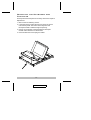
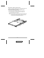
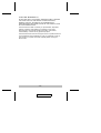
User Manual CS-1200L Read this guide thoroughly and follow the installation and operation procedures carefully in order to prevent any damage to the units and/or any devices that connect to them. This package contains: M M M M M 1 1 1 1 1 CS-1200L Slideaway Console KVM Connector Cable AC Power Cord Rack Mounting Kit User Manual If anything is damaged or missing, contact your dealer. © Copyright 2003 ATEN® International Co., Ltd. Manual Part No. PAPE-1232-100 Printed in Taiwan 08/2003 All brand names and trademarks are the registered property of their respective owners. 2003-07-31 Warning! This is a class A product. In a domestic environment this product may cause radio interference in which case the user may be required to take adequate measures. This equipment has been tested and found to comply with the limits for a Class A digital device, pursuant to Part 15 of the FCC Rules. These limits are designed to provide reasonable protection against harmful interference when the equipment is operated in a commercial environment. This equipment generates, uses and can radiate radio frequency energy and, if not installed and used in accordance with the instruction manual, may cause harmful interference to radio communications. Operation of this equipment in a residential area is likely to cause harmful interference in which case the user will be required to correct the interference at his own expense. 2003-07-31 Overview The CS-1200L is a KVM console module featuring an integrated 15" LCD panel, full keyboard, and touchpad in a 1U, rack-mountable, Slideaway housing. It was developed in response to the enormous popularity of the Slideaway console found on the ACS-1208AL and ACS-1216AL KVM switches. The ACS-1208AL/ACS-1216AL is made up of two major modules: the front-end Slideaway KVM Console module, and the back-end KVM Switch module. The CS-1200L is similar to the Console module found on the ACS-1208AL/ACS-1216AL, except it has been redesigned to serve as the front end for other Master View KVM switches, as well. By only having to purchase the CS-1200L console module, users who already have a Master View switch can take advantage of the space saving and efficiency benefits of the ACS-1208AL/ACS-1216AL’s Slideaway console without the unnecessary expense of having to purchase its KVM Switch module. Setup is fast and easy. Simply use the supplied KVM connector cable to link the CS-1200L’s KVM ports to the console ports of your KVM switch and you are ready to go.* * The CS-1200L supports most Master View KVM switches that have PS/2 console port connectors. If you are unsure if your switch is supported, check with your dealer or call Aten Customer Service. -1- 2003-07-31 Features M KVM console (15" LCD display - 88-key keyboard touchpad) in an integrated 1U rack-mountable Slideaway housing M Protects former Master View KVM switch investment M Enjoy the space-saving, efficiency benefits of the ACS-1208AL/ACS-1216AL’s 1U rack-mountable Slideaway console without the expense of its KVM switch module M Keyboard/Touchpad section is easily removed for quick repair or replacement M Sleep mode when the Slideaway cover is closed M Superior video quality - supports resolutions of up to 1024 x 768 M Rack mountable in 19" system rack (1U) Hardware Requirements M The CS-1200L supports most Master View KVM switches that have PS/2 console port connectors. If you are unsure if your switch is supported, check with your dealer or call Aten Customer Service. M For optimum signal integrity we strongly recommend you use the CS Custom KVM cable that was supplied with this package. -2- 2003-07-31 Front View 1 2 3 8 7 6 4 5 1. Handle Pull to slide the KVM module out; push to slide the module in. 2. LCD Monitor After sliding the KVM module out, flip up the cover to access the LCD monitor, keyboard and touchpad. 3. Keyboard 4. Power LED Lights BLUE to indicate that the unit is receiving power. -3- 2003-07-31 5. Slide Release There is a mechanism that locks the Slideaway console in the “In” position to prevent it from accidentally sliding out. To slide the the console out, you must first release it by moving this tab sideways. 6. Rack Mounting Brackets There are rack mounting brackets to secure the chassis to a system rack located at each corner of the unit. See p. 10 for rack mounting details. 7. Touchpad 8. LCD Display Controls The LCD On/Off Switch is located here, as well as buttons to control the position and picture settings of the LCD display. See the LCD OSD Configuration section p. 8, for details. -4- 2003-07-31 Rear View 1 3 2 4 1. Cable Tie Slot If you want to use a cable tie to gather the cables together, you can run it through this slot to attach it to the unit. 2. Console Port Section The KVM Connector cable that links the CS-1200L to your KVM switch plugs in here. Each port is color coded and labeled with an icon to identify itself. 3. Power Socket The power cord to the AC source plugs in here. 4. Power Switch This is a standard rocker switch that powers the unit On and Off. -5- 2003-07-31 Installation 1. Before you begin, make sure that power to all the devices you will be connecting up have been turned off. You must unplug the power cords of any computers that have the Keyboard Power On function. 2. To prevent damage to your installation, make sure that all devices are properly grounded. Refer to the example installation diagram on the next page as you perform the following steps: 1. Plug the keyboard, monitor, and mouse connectors of the KVM Connector cable provided with this unit into the appropriate Console ports of the CS-1200L. Each port is color coded and labeled with an icon to identify itself. 2. Plug the keyboard, monitor, and mouse connectors of the KVM Connector cable into their respective ports on the Console Section of the KVM switch. 3. Plug the power cord into the CS-1200L’s power socket and into an AC power source. 4. Power up your KVM installation. 5. Turn on the power to CS-1200L. Note: The example diagram shows the CS-1200L connecting to an ACS-1216A KVM switch. If you are connecting to a different model, the console port connectors may be in a different location. -6- 2003-07-31 2 1 3 -7- 2003-07-31 LCD OSD Configuration The LCD OSD allows you to set up and configure the LCD display: M To bring up the LCD OSD main menu, press the button marked Menu. M Use the ▲ and ▼ buttons to navigate and make adjustments with; after navigating to a setting choice, use the Menu button to bring up the adjustment screen. M When making adjustments, ▲ increases the value; ▼ decreases the value. M When you are satisfied with your adjustment, press Exit to return to the OSD main menu. M When all your adjustments have been made, press Exit to close the LCD OSD. An explanation of the settings is given in the table below: Auto Adjust Automatically configures all the settings for the LCD panel to what the OSD considers the optimum values Brightness Adjusts the background black level of the screen image. Contrast Adjusts the foreground white level of the screen image. Phase Adjusts the vertical size of the screen image. Clock Adjusts the horizontal size of the screen image. H-Position Positions the display area on the LCD panel horizontally (moves the display area left or right). V-Position Positions the display area on the LCD panel vertically (moves the display area up or down). Color Adjustment Adjusts the color quality of the display. You can adjust the “warmth” value, color balance, etc. The Adjust Color selection has a further submenu that lets you fine tune the RGB values. Language Selects the language that the OSD displays its menus in. Recall Resets the adjustments on all menus and submenus to their factory default settings. -8- 2003-07-31 Removing the Keyboard and Touchpad The keyboard and touchpad can be easily removed for repair or replacement: 1. Remove the two attaching screws. 2. Locate the opening toward the front and center of the the unit’s bottom panel. The bottom of the keyboard and touchpad module is visible through the opening. 3. Push up on the bottom of the keyboard and touchpad module until it releases from the chassis. 4. Lift the module clear and unplug the cables. -9- 2003-07-31 Rack Mounting The CS-1200L can be mounted in a 1U system rack. For convenience and flexibility, a rack mounting kit that allows several mounting options is provided with your CS-1200L package. The various options are explained in the sections that follow. Standard Rack Mounting The standard rack mounting brackets that come attached to the CS-1200L allow the unit to be installed in standard 1U racks. If the unit can fit into your rack “as is,” simply slide it into the rack and screw it securely in place. - 10 - 2003-07-31 Optional Rack Mounting If there is not enough clearance for the unit to slide into the rack when the rear flanges face outward, the problem can be resolved with the following procedure: 1. Unscrew the rear mounting brackets from the chassis. 2. Turn the brackets so that the flanges face inward; then screw them back into the chassis. Note: Be sure to leave a 13mm gap between the flange and the rear of the chassis in order to have enough room to screw the tab to the flange (see step 4). - 11 - 2003-07-31 3. Slide the unit into the rack. 4. Screw the metal tabs to the rear flanges. 5. Secure the unit to the rack with the front flanges and rear tabs. - 12 - 2003-07-31 Specifications Function Connectors Specification Keyboard 1 x 6 pin mini-DIN female Mouse 1 x 6 pin mini-DIN female Video 1 x HDB-15 male Power 1 x AC Input socket LEDs 1 x Power (Blue) Resolution 1024 x 768; DDC2B Environment Operating Temperature: 0 - 50o C Storage Temperature: -20 - 60o C Humidity: 0 - 80% RH Noncondensing Housing Metal Weight 12.2 Kg Dimensions (L x W x H) 59.59 x 48.28 x 4.44 cm - 13 - 2003-07-31 Limited Warranty IN NO EVENT SHALL THE DIRECT VENDOR’S LIABILITY EXCEED THE PRICE PAID FOR THE PRODUCT FROM THE DIRECT, INDIRECT, SPECIAL, INCIDENTAL OR CONSEQUENTIAL DAMAGES RESULTING FROM THE USE OF THE PRODUCT, DISK OR ITS DOCUMENTATION. The direct vendor makes no warranty or representation, expressed, implied, or statutory with respect to the contents or use of this documentation, and specially disclaims its quality, performance, merchantability, or fitness for any particular purpose. The direct vendor also reserves the right to revise or update the device or documentation without obligation to notify any individual or entity of such revisions, or update. For further inquires please contact your direct vendor. - 14 - 2003-07-31