1
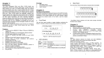
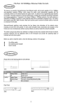
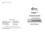
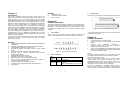
Package Chapter 1: z Introduction This newly redesigned 5Port and 8Port 10/100 Switch can significantly increase your network traffic speed. A switch serves the same function as a hub in a network design tying your network equipment together. But unlike a simple-minded hub which divides the network’s bandwidth among all the attached devices, a switch delivers full network speeds at each port. Installing this cost-effective 5Port and 8Port 10/100 Switch can potentially increase your network speed by five, eight times! It's the perfect way of integrating 10Mbps Ethernet and 100Mbps Fast Ethernet devices, too. All ports are auto speed negotiating, and have automatic MDI/MDI-X crossover detection, so you don’t have to worry about the cable type. Each port independently negotiates for best speed and half- or full-duplex mode, for up to 200Mbps of bandwidth per port. Fast store-and-forward switching prevents damaged packets from being passed on into the network. The new, ultra-compact case design is sure to fit into your workgroup environment. Let the 5, 8Port 10/100 Switch kick your 10/100 network into high gear. z z One NWay switch One external power adapter User’s manual The rear panel of the 5/8 Port Switch indicates 5/8 RJ-45 PORT. Chapter 2: Hardware Description This section describes the hardware Features of the 5/8 Port Switch. familiarize yourself with its display indicators, and ports. Front panel illustrations in this chapter display the unit LED indicators. Before connecting any network device to the Switch, read this chapter carefully. Front Panel The unit front panel provides a simple interface monitoring the Switch. It includes a power led and 5/8 led indicator for each port. Figure of The 5/8Port Switch indicates a AC inlet, which accepts 100-240V 50-60Hz Power adapter. Chapter 3: z z z z z z z z z z z z z z Complies with the IEEE802.3 10Base-T Ethernet, IEEE802.3u 100Base-TX 5/8 ports 10/100Mbps TX Auto-Negotiation Ethernet Switch Full/Half-Duplex capability on every TX port Supports TP interface Auto MDIX function for auto TX/RX swap Automatic Source MAC Address Learning and Aging Supports Store & Forward architecture and performs forwarding and filtering Broadcast Storming Filter function IEEE802.3x flow control for Full-duplex Back Pressure function for Half-duplex operation Runt and CRC Filtering eliminates erroneous packets to optimize the network bandwidth Support to handle up to 1522 bytes packet LED indicators for simple diagnostics and management Plug and Play 1 5/8 Port Smart Switch rear panel Hardware Installation Features z Rear Panel z z Figure of 5/8 Port Switch front panel LED indicators LED Function PWR Color Green LNK/ACT Green Description Lit: Power on Lit: Indicates the adapter is connected to switch Flash: Indicates data in or out the port 2 Place the Switch on a smooth surface Connect the output of power adapter to the DC-inlet of the Switch. Connect other IEEE802.3 compatible network device(Hub ,Switch ,PC) to one port of the Switch using Category 3/4/5 UTP/STP cabling. Connect another IEEE802.3 compatible network device (Hub , Switch ,PC) to another port of the Switch by following the same process as described in Step3. Notice: The cable distance between the Switch and other IEEE802.3 compatible network device should not exceed 100 meter. Make sure the wiring is correct It can be used Category 3/4/5 cable in 10 Mbps operation. To reliably operate your network at 100Mbps, you must use an Unshielded/shielded Twisted-Pair (UTP/STP) Category 5 cable, or better Data Grade cabling. While a Category 3 or 4 cable may initially seem to work, it will soon cause data loss. All kinds of IEEE802.3 compatible network device (Hub , Switch ,PC)can connect to the Switch by using straight-through wires or crossover wires because of Switch’s auto MDIX function. 3 Chapter 4: Chapter 5: Hardware Troubleshooting Specifications This chapter contains information to help you solve problems. If the Switch is not functioning properly, make sure the Switch was set up according to instructions in this manual. 1. 2. 3. 4. The Power LED is not lit Solution: a. Check if the DC power adapter is well connected. Try to unplug and plug back the power adapter to the LAN Switch or try another power adapter. b. Check if the DC power source is in good condition. The Link LED is not lit Solution: a. Make sure the Switch configuration is consistent with the connecting device b. Check the cable connections. c. Make sure the cable distance between the Switch and other IEEE802.3 compatible network device should not exceed 100 meter. Performance is bad Solution: a. Check the full duplex status of the Ethernet Switching. If the Ethernet Switching is set to full duplex and the partner is set to half duplex, then the performance will be poor. b. Make sure the cable between the switch and other IEEE802.3 compatible network device is Category 5 UTP at 100Mbps operation. Some stations can not talk to other stations located on the other port Solution: a. Check status of the Link LED to make sure the link is correct. b. Make sure that the workstation’s network configuration is correct, modify the network configuration of workstation if need. c. Please reset the switch if need. z Standard: IEEE802.3 10Base-T Ethernet IEEE802.3u 100Base-TX Fast Ethernet z Network Media: 100Base-TX – UTP/STP category 5 cable 10Base-T – UTP/STP category 3 or 5 cable z Connector: STP RJ-45 port for 10/100Mbps TX z LED indicators: System – User Manual Power LED. Individual port – link/activity LEDs z z Dimension: 160mm(L) x 83mm(W) x 26mm(H) Temperature: Operating – Storage – z 0℃ to 45℃ -20℃ to 70℃ Humidity: Operating – Storage – 10% to 90% RH 5% to 90% RH z Input Power Requirement: 100 - 240VAC, 50 – 60Hz z Certification: FCC Part 15 Class A, CE (P/N: 41NE-170508KB-A04) 4 5/8-port 10/100Mbps Nway Fast Ethernet Switch 5