1
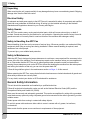
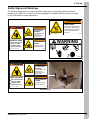
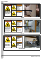
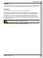
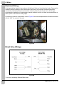
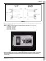
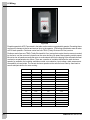
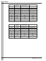
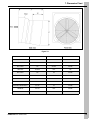
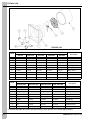
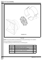
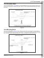
APP Series Fans
Installation and Operation Manual
PNEG-876
Date: 05-07-14
PNEG-876
APP Series Fans are manufactured, assembled and packaged with the highest standard of quality
assurance. Please inspect and notify the factory in the unlikely event you discover defects in
workmanship. We appreciate hearing from you and will correct immediately.
Read carefully before attempting to assemble, install, operate or maintain the product described. Protect
yourself and others by observing all safety information. Use only genuine AP/Cumberland parts in the
installation of fans, use of non-genuine parts or failure to comply with instructions could result in personal
injury and/or property damage. This fan is not designed for use in atmospheres where risk of explosion is
foreseen. Such environments may include enclosed areas of high dust concentrations, gas vapors and
fumes. Use in such an atmosphere is prohibited. If in doubt contact AP/Cumberland or your dealer.
Retain instructions for future reference.
Fan Models
CFM at 0.00 SP
Weight Lbs./kgs
Cubic Ft./mtrs
APP-12F*
1700
37 Lbs./16.80 kgs
8.7 Ft./0.25 mtrs
APP-14F*
2487
47 Lbs./21.30 kgs
8.7 Ft./0.25 mtrs
APP-14FC*
2830
55 Lbs./25.00 kgs
14 Ft./0.40 mtrs
APP-18F*
4387
54 Lbs./24.50 kgs
18.2 Ft./0.52 mtrs
APP-18FC*
5090
65 Lbs./29.50 kgs
26.7 Ft./0.76 mtrs
APP-24F*
6442
75 Lbs./34.00 kgs
19.9 Ft./0.56 mtrs
APP-24FC*
7530
90 Lbs./40.80 kgs
34.2 Ft./0.97 mtrs
APP-36F*
11113
127 Lbs./57.60 kgs
34.5 Ft./0.97 mtrs
APP-36FC*
12290
162 Lbs./73.50 kgs
55.7 Ft./1.58 mtrs
APPB-36*
11113
135 Lbs./61.20 kgs
34.5 Ft./0.97 mtrs
APPB-36C*
12290
170 Lbs./77.10 kgs
55.7 Ft./1.58 mtrs
APPB-50*
20856
214 Lbs./97.00 kgs
65 Ft./1.85 mtrs
APPB-50C*
23894
265 Lbs./120.20 kgs
65 Ft./1.85 mtrs
* Add - BLK suffix to end of fan model number for black fans.
VFD Fan Models
CFM at 60 Hz
CFM at 0.00 SP
Weight Lbs.
Cubic Ft.
APP-12F-VFD
1700
48 Lbs.
8.7 Ft.
APP-14F-VFD
2480
54 Lbs.
8.7 Ft.
APP-14FC-VFD
2830
62 Lbs.
14 Ft.
APP-18F-VFD
4380
64 Lbs.
18.2 Ft.
APP-18FC-VFD
5090
75 Lbs.
26.7 Ft.
APP-24F-VFD
6440
87 Lbs.
19.9 Ft.
APP-24FC-VFD
7250
102 Lbs.
34.2 Ft.
For guidance or assistance on any issues relating to the safe use of your APP Fan contact
AP/Cumberland.
Our address is:
Cumberland
1004 E. Illinois St.
Assumption, IL. 62510
Phone: 1-217-226-4421
2
PNEG-876 APP Series Fans
Table of Contents
Contents
Chapter 1 Safety .....................................................................................................................................................4
Safety Guidelines ...................................................................................................................................4
Safety Instructions ..................................................................................................................................5
General Safety Information ....................................................................................................................6
Chapter 2 Decals ....................................................................................................................................................7
Safety Signs and Warnings ....................................................................................................................7
Chapter 3 Installation ............................................................................................................................................9
Chapter 4 Operation ............................................................................................................................................10
Chapter 5 Maintenance ........................................................................................................................................11
Cleaning ...............................................................................................................................................11
Lubrication ............................................................................................................................................11
Greasing Pillow Block Bearings in Belt Driven Fan Applications .........................................................11
Chapter 6 Wiring ..................................................................................................................................................12
Electrical Wiring ...................................................................................................................................12
Direct Drive Wirings .............................................................................................................................12
Chapter 7 Dimension Chart .................................................................................................................................17
Chapter 8 Parts List .............................................................................................................................................18
Chapter 9 50" Cone Assembly ............................................................................................................................20
Cone Assembly Detail ..........................................................................................................................21
Cone Mounting Detail ...........................................................................................................................21
Guard Detail .........................................................................................................................................22
Chapter 10 Warranty ............................................................................................................................................23
PNEG-876 APP Series Fans
3
1. Safety
Safety Guidelines
This manual contains information that is important for you, the owner/operator, to know and understand.
This information relates to protecting personal safety and preventing equipment problems. It is the
responsibility of the owner/operator to inform anyone operating or working in the area of this equipment
of these safety guidelines. To help you recognize this information, we use the symbols that are defined
below. Please read the manual and pay attention to these sections. Failure to read this manual and its
safety instructions is a misuse of the equipment and may lead to serious injury or death.
This is the safety alert symbol. It is used to alert you
to potential personal injury hazards. Obey all safety
messages that follow this symbol to avoid possible
injury or death.
DANGER
WARNING
4
DANGER indicates a hazardous situation which, if not
avoided, will result in death or serious injury.
WARNING indicates a hazardous situation which, if not
avoided, could result in death or serious injury.
CAUTION
CAUTION, used with the safety alert symbol, indicates a
hazardous situation which, if not avoided, could result in
minor or moderate injury.
NOTICE
NOTICE is used to address practices not related to
personal injury.
PNEG-876 APP Series Fans
1. Safety
Safety Instructions
Our foremost concern is your safety and the safety of others associated with this equipment. We want to
keep you as a customer. This manual is to help you understand safe operating procedures and some
problems that may be encountered by the operator and other personnel.
As owner and/or operator, it is your responsibility to know what requirements, hazards, and precautions
exist, and to inform all personnel associated with the equipment or in the area. Safety precautions may be
required from the personnel. Avoid any alterations to the equipment. Such alterations may produce a very
dangerous situation where SERIOUS INJURY or DEATH may occur.
This equipment shall be installed in accordance with the current installation codes and applicable
regulations, which should be carefully followed in all cases. Authorities having jurisdiction should be
consulted before installations are made.
Follow Safety Instructions
Carefully read all safety messages in this manual and
safety signs on your machine. Keep signs in good
condition. Replace missing or damaged safety signs. Be
sure new equipment components and repair parts include
the current safety signs. Replacement safety signs are
available from the manufacturer.
Learn how to operate the machine and how to use controls
properly. Do not let anyone operate without instruction.
Keep your machinery in proper working condition.
Unauthorized modifications to the machine may impair
the function and/or safety and affect machine life.
Read and Understand Manual
If you do not understand any part of this manual or need
assistance, contact your dealer.
User Manual
This manual contains information and instructions essential to the safe installation and use of the
APP Fan. Read this manual thoroughly before attempting any installation or use of the APP Fan. Keep
this manual with the APP Fan or in a location where it can be readily accessed. Failure to read this manual
and its safety instructions is a misuse of the equipment.
Correct Use of the APP Fan
The APP Fan is designed solely for the purpose of ventilating agricultural buildings. Use of the system in
any other way is a misuse of the system and may endanger safety and health.
Only genuine AP/Cumberland parts are to be used in the installation and use of the APP Fan. Use of other
non-genuine parts is a misuse of the system and may lead to dangerous situations imperilling the safety
and health of you and others.
This machine is not designed for use in atmospheres where there is a risk of explosion. Such
environments may include enclosed areas of high dusts concentrations, gas vapors and fumes. Use of the
APP Fan in such an environment is prohibited. If in doubt, contact AP/Cumberland or your dealer.
PNEG-876 APP Series Fans
5
1. Safety
Unpacking
When receiving the unit, inspect carefully for any damage that may have occurred during transit. Shipping
damage claim must be filed with carrier.
Electrical Safety
An adequate and safe power supply to the APP Fan unit is essential for safety. A competent and qualified
electrician must undertake all electrical wiring. All wiring is to be installed according to the National
Standards and Regulations relevant to your Country and Region.
Safety Guards
The APP Fan contains many moving and electrical parts, which will cause serious injury or death if
touched. Guards are placed on the machine for your protection. Operating the machine at any time with
guards removed or incorrectly fitted is a serious misuse of the machine and endangers safety.
Safety in Handling the APP Fan
Manual handling of the fans can be a cause of serious injury. Wherever possible, use mechanical lifting
equipment when lifting or moving fans during installation. Where manual handling is required, seek
assistance from other people.
To prevent injury, use suitable hand protection.
Safety in Maintenance
While the APP Fan is designed to keep maintenance to a minimum, some repairs will be necessary in the
course of the life of the machine. Do not attempt any repairs on the machine unless you are competent to
do so. Remember that the APP Fan may in cases operate under automatic control and start without
warning. Never attempt any work on the APP Fan without first isolating the machine from the mains power
and locking the isolator so that only you can turn the power back ON.
Follow all the guidelines given in the maintenance section on Page 11 of this manual.
Before restarting the APP Fan, ensure that all electrical enclosures are locked closed and all guards and
other safety measures are correctly fitted.
If in any doubt, contact your dealer or AP/Cumberland for assistance.
General Safety Information
This unit should be assembled and installed by a qualified technician.
Follow all local electrical and safety codes, as well as the National Electrical Code (NEC) and the
Occupational Safety and Health Act (OSHA).
Motor must be securely and adequately grounded. This can be accomplished by wiring with a grounded,
metal-clad raceway system by using a separate ground wire connected to the motor’s ground lug or other
suitable means.
Protect power cable from coming in contact with sharp objects.
Do not kink power cable and never allow cable to come in contact with oil, grease, hot surfaces,
or chemicals.
Make certain that the power source conforms to requirements of the equipment.
6
PNEG-876 APP Series Fans
2. Decals
Safety Signs and Warnings
The following pages show you exactly where the safety signs and warnings (decals) should be
placed on your APP Fan. If a decal is missing, damaged or unreadable, please contact your dealer
or AP/Cumberland for a free replacement.
WARNING
SHEAR POINT
DANGER
Keep hands clear of moving
parts. Do not operate with
guard removed. Disconnect
and lockout power before
servicing.
WARNING
STAY CLEAR OF
ROTATING BLADE
Blade may start
automatically.
May cause serious injury.
GSI Group Inc. 217-226-4421
DC-995
Disconnect and
lockout power sources
before servicing.
HIGH VOLTAGE
Will cause serious
injury or death.
Lockout power
before servicing.
The GSI Group 217-226-4421
WARNING
FLYING OBJECTS
HAZARD
WARNING
Danger of eye injury.
Wear eye protection.
DC-1540
DC-1018
DANGER
WARNING
STAY CLEAR OF
ROTATING BLADE
Blade may start
automatically.
May cause serious injury.
Disconnect and
lockout power sources
before servicing.
HIGH VOLTAGE
Will cause serious
injury or death.
Lockout power
before servicing.
The GSI Group 217-226-4421
WARNING
FLYING OBJECTS
HAZARD
Danger of eye injury.
Wear eye protection.
DC-1540
Inside housing
PNEG-876 APP Series Fans
7
2. Decals
DANGER
WARNING
STAY CLEAR OF
ROTATING BLADE
Blade may start
automatically.
May cause serious injury.
Disconnect and
lockout power sources
before servicing.
HIGH VOLTAGE
Will cause serious
injury or death.
Lockout power
before servicing.
The GSI Group 217-226-4421
WARNING
FLYING OBJECTS
HAZARD
Danger of eye injury.
Wear eye protection.
DC-1540
Left side
DANGER
WARNING
STAY CLEAR OF
ROTATING BLADE
Blade may start
automatically.
May cause serious injury.
Disconnect and
lockout power sources
before servicing.
HIGH VOLTAGE
Will cause serious
injury or death.
Lockout power
before servicing.
The GSI Group 217-226-4421
WARNING
FLYING OBJECTS
HAZARD
Danger of eye injury.
Wear eye protection.
DC-1540
Right side
DANGER
WARNING
STAY CLEAR OF
ROTATING BLADE
Blade may start
automatically.
May cause serious injury.
Disconnect and
lockout power sources
before servicing.
HIGH VOLTAGE
Will cause serious
injury or death.
Lockout power
before servicing.
The GSI Group 217-226-4421
WARNING
FLYING OBJECTS
HAZARD
Danger of eye injury.
Wear eye protection.
DC-1540
Motor mount plate
8
PNEG-876 APP Series Fans
3. Installation
Fans should be installed in an exterior wall located where there will be no obstructions to the flow of air
into or out of the fan.
Once a location has been determined, an opening should be made in the wall and framed to provide
enough clearance around the fan housing. (See rough opening chart on Page 10.)
Framing must be able to support the weight of the fan assembly.
Manual handling of the fans may result in serious injury. Where appropriate, use mechanical methods of
lifting during installation. Where manual handling is required, ensure you have adequate assistance.
Position fan assembly in the framed opening. Rigidly mount the housing side flanges to the framework
using mounting screws.
Remove electrical cover and connect power leads to motor terminals, using approved wiring method.
It is recommended to use the watertight connector included with the motor, if it is possible in the
application. (Motor terminal connection data is provided on motor nameplate and in this manual.) Use
adequate size wire for all branch and feeder runs. When speed control is used, follow the installation
procedures recommended by the speed control manufacturer.
Re-install electrical cover.
Unit is now ready for operation.
PNEG-876 APP Series Fans
9
4. Operation
Fan Model
Width (in.)
Inside Height (in.)
Outside Height (in.)
(B)
4" Wall (A)
6" Wall (A)
8" Wall (A)
APP-12*
17
17-1/2
16-1/2
16
15-1/2
APP-14*
20
20
19-1/4
18-7/8
18-1/2
APP-18*
25-1/2
26
25
24-1/2
24
APP-24*
34-1/2
34-1/2
33-1/2
33
32-1/2
APP-36*
44-1/2
44-1/2
43-1/2
43
42-1/2
APPB-36*
44-1/2
44-1/2
43-1/2
43
42-1/2
APPB-50*
56
56
55
54-1/2
54
* Add - BLK suffix to end of fan model for black fans.
Figure 4A
Units may be operated using a switch, thermostat, timer or controller.
Follow wiring and operation instructions furnished with the control system selected.
When using speed controllers, follow the operation procedures recommended by the
controller manufacturer.
1. Set thermostat setting to a desired temperature. Fan will operate only when ambient temperature is
above the thermostat set temperature.
2. Some controllers have idle speed controls. Set idle speed such that the blade RPM is within the
RPM range listed in the performance table.
10
PNEG-876 APP Series Fans
5. Maintenance
Cleaning
It is advisable to clean blade and shutter at regular intervals. This will remove any accumulated dirt, which
would cause fan blade to become unbalanced and result in excessive vibration and poor performance.
Lubrication
Motor is pre-lubricated at factory and will not require any further lubrication.
Greasing Pillow Block Bearings in Belt Driven Fan Applications
Bearings should be re-lubricated every 30 operating days and/or after each wash down cycle with
three (3) shots of grease or until fresh grease is seen purging past seal. Lithium or lithium-complex
based #2 NLGI grease must be used. Other types of grease are incompatible with the factory lubricant
and will damage the bearing.
DO NOT use a pneumatic or powered grease gun.
CAUTION
Incompatible grease or lack of service will void bearing warranty.
PNEG-876 APP Series Fans
11
6. Wiring
Electrical Wiring
All wiring should be installed in accordance with National, State and Local electrical codes. Fans used to
ventilate livestock buildings or other rooms where continuous air movement is essential should be
connected to individual electrical circuits, with a minimum of two (2) circuits per room. We strongly
recommend the installation of supplementary natural ventilation as well as a back-up thermostat and an
alarm system on at least one cooling stage.
For electrical connection requirements, refer to Figure 6A on motor nameplate and to information enclosed
with the “AVS” fan control to be used.
Figure 6A
Direct Drive Wirings
Figure 6B
To reverse, interchange Red and Black leads.
12
PNEG-876 APP Series Fans
6. Wiring
Figure 6C
Motor overload protection should be provided for each fan. A circuit breaker switch or slow blow motor
type fuses must be used.
NOTE: A safety cut-off switch should be located adjacent to each fan, such as “AP” #’s:
E100-A1063 - 2-1/2 Amp
E100-A1064 - 5.0 Amp
E100-A1065 - 8.0 Amp
E100-A1066 - 15.0 Amp
Figure 6D
Back-up thermostats such as the TH-1, should always be used in conjunction with the control system.
These should be placed on a separate circuit to give the animals ventilation in the event that the
controller fails.
PNEG-876 APP Series Fans
13
6. Wiring
Figure 6E
Propeller speeds for APP Fans stated in the table are the maximum permissible speeds. Exceeding these
may result in damage to the fan and serious injury to the operator. CFM ratings listed below were all taken
at 0.05 static pressure. Performer series fans use TEAO (Totally Enclosed Air Over) motors.
Performer series fans use TEAO (Totally Enclosed Air Over) motors that require the air movement created
by the fan to cool the motor as it passes over the motor housing. Be aware that operating variable speed
fans at too low of speed can cause the motor to overheat and result in the tripping of the automatic thermal
overload or unwarranted motor failure. There are a number of variables that affect the safe minimum
speed of a ventilation fan including ventilation control curve selection, input voltage, static pressure and
susceptibility to head winds. The correct minimum speed must be selected on a case by case basis to
ensure adequate airflow for motor cooling.
APP-12F*
Speed Curve #9
Volts
RPM
CFM without Cone
CFM with Cone
230
1765
1432
N/A
135
1675
1351
N/A
119
1575
1251
N/A
115
1475
1133
N/A
112
1375
983
N/A
111
1275
964
N/A
109
1175
780
N/A
107
1075
700
N/A
105
975
590
N/A
104
875
520
N/A
103
775
445
N/A
102
675
380
N/A
101
575
310
N/A
99
475
242
N/A
* Add - BLK suffix to end of fan model for black fans.
14
PNEG-876 APP Series Fans
6. Wiring
APP-14F*
Speed Curve #7
Volts
RPM
CFM without Cone
CFM with Cone
230
1765
2367
2631
151
1675
2230
2487
145
1575
2100
2292
144
1475
1953
2130
143
1375
1808
2018
142
1275
1659
1813
140
1175
1471
1581
139
1075
1242
1487
137
975
1044
1280
135
875
854
1023
131
775
558
489
130
675
290
263
121
575
167
160
* Add - BLK suffix to end of fan model for black fans.
APP-18F*
Speed Curve #8
Volts
RPM
CFM without Cone
CFM with Cone
230
1765
3651
4394
174
1675
3480
4221
158
1575
3251
3898
142
1475
3012
3664
137
1375
2786
3480
133
1275
2508
3168
129
1175
2202
2788
126
1075
1990
2431
122
975
1710
2102
118
875
1396
1722
113
775
821
1401
109
675
566
762
107
575
273
298
103
475
112
153
* Add - BLK suffix to end of fan model for black fans.
PNEG-876 APP Series Fans
15
6. Wiring
APP-24F*
Speed Curve #4
Volts
RPM
CFM without Cone
CFM with Cone
230
1040
5798
7386
194
940
5160
6353
176
840
4784
5648
157
740
3830
4688
143
640
2875
3842
130
540
2072
2902
115
440
823
1596
103
340
368
331
* Add - BLK suffix to end of fan model for black fans.
APP-36F*
Speed Curve #5
Volts
RPM
CFM without Cone
CFM with Cone
230
850
9260
11000
202
750
7894
9421
197
650
6587
7764
195
550
5482
6293
192
450
3516
2953
188
350
1286
1362
* Add - BLK suffix to end of fan model for black fans.
16
PNEG-876 APP Series Fans
7. Dimension Chart
Figure 7A
Fan Model
“A”
“B”
“C”
APP-12F*
25-5/8"
N/A
12-1/2"
APP-14F*
21"
N/A
15-1/2"
APP-14FC*
40"
20-5/8"
20-5/8"
APP-18F*
22-3/16"
N/A
20"
APP-18FC*
40"
22"
25-3/8"
APP-24F*
22"
N/A
26"
APP-24FC*
41"
23-3/8"
31-7/8"
APP-36F/APPB-36F*
30-1/4"
N/A
37-7/8"
APP-36FC/APPB-36FC*
54-1/2"
27"
44-3/8"
APPB-50*
34-1/4"
N/A
50-3/8"
APPB-50C*
55"
24"
56-3/8"
* Add - BLK suffix to end of fan model for black fans.
PNEG-876 APP Series Fans
17
8. Parts List
Part #
Ref #
APP-12F
APP-14FC
APP-18FC
APP-24FC
Description
APP-36FC
1
N/A
12-0087F
12-0085F
12-0080F
12-0093
Cone *
2
11-0045-WH
11-0200-WH
11-0201-WH
11-0202-WH
11-0203-WH
Grill *
3
13-0130
13-0106
13-0107
13-0209
13-0129
Prop
4
12-0117
12-0086F
12-0084F
12-0083F
12-0091
Housing *
5
15-0109
15-0109
15-0110
15-0105
15-0116
Motor
6
11-0217
11-0193
11-0190
11-0181
11-0212
Motor Mount
7
N/A
11-0194
11-0192
11-0219
N/A
Right Motor Mount
8
N/A
11-0195
11-0191
11-0218
N/A
Left Motor Mount
PS-15SC
PS-18C
PS-24C
PS-32C
PS-42C
PVC Shutter *
N/S
Part #
Ref #
APP-12F-VFD
APP-14FC-VFD
APP-18FC-VFD
Description
APP-24FC-VFD
1
N/A
12-0087F
12-0085F
12-0080F
Cone *
2
11-0045-WH
11-0200-WH
11-0201-WH
11-0202-WH
Grill *
3
13-0130
13-0106
13-0107
13-0209
Prop
4
12-0117
12-0086F
12-0084F
12-0083F
Housing *
5
15-0203
15-0203
15-0205
15-0206
Motor
6
11-0217
11-0193
11-0190
11-0181
Motor Mount
7
N/A
11-0194
11-0192
11-0219
Right Motor Mount
8
N/A
11-0195
11-0191
11-0218
Left Motor Mount
PS-15SC
PS-18C
PS-24C
PS-32C
PVC Shutter *
N/S
* For black fans add -BLK suffix after the housing, cone, grill and PVC shutter part numbers.
18
PNEG-876 APP Series Fans
8. Parts List
Part #
Ref #
APPB-36C and APPB-36CHP
Description
APPB-50C
1
12-0093
12-0094
Cone (Optional) *
2
11-0203-WH
11-0325 (Cone) /
11-0204-WH (No Cone)
Grill *
3
13-0062 / (HP) 13-0223
13-0044
Prop
4
12-0091
12-0092
Housing *
5
11-0464
11-0208
Bearing Plate
6
11-0465
11-0209
Motor Mount Leg
7
91-0057
91-0057
Tensioner Arm
8
(1Ø) 15-0032 / (3Ø) 15-0086 / (HP) 15-0212
(1Ø) 15-0029 / (3Ø) 15-0084
Motor
9
16-0016 / (HP) 1011-2638
16-0016
Motor Sheave
10
16-0091
16-0012
Belt
11
16-0014
16-0099
Driven Pulley
12
(CR) 16-0083 / (SS) 16-0004 / (HP) 12-0477
(CR) 16-0083 / (SS) 16-0004
Shaft
13
1016-0100
1016-0100
Bearing
N/S
PS-42C
PS-54C
PVC Shutter *
N/S
HD42
HD54-F
Optional Aluminum Shutter
* For black fans add -BLK suffix after the housing, cone, grill and PVC shutter part numbers.
PNEG-876 APP Series Fans
19
9. 50" Cone Assembly
Figure 9A
NOTE: Fan must be installed in the wall before proceeding with discharge cone installation.
Remove packaging from cone and guard sections.
Find hardware package #10-0068 consisting of the following parts:
Part #
20
Description
Qty
S-8724
Fender Washer 5/16" x 1-1/2" x 1/16" SS
38
S-8452
Flange Nut 5/16"-18 SS Waxed (Must be Waxed)
20
S-7447
Flange Bolt 5/16"-18 x 1" SS (Full Thread)
7
S-8168
Flange Bolt 5/16"-18 x 1-1/2" SS
13
PNEG-876 APP Series Fans
9. 50" Cone Assembly
Cone Assembly Detail
See cone assembly detail in Figure 9B below. Partially assemble the cone on the ground by using only the
outermost two (2) holes per overlap (six (6) total). Use the 1" bolts, fender washers and flange nuts, leaving
bolts loose.
Figure 9B
Cone Mounting Detail
See cone mounting detail in Figure 9C below. Place the cone on the fan leaving a 2" overlap. Mark the
nine (9) holes around fan orifice. Remove cone and drill 7/16" holes where marked. Mount the cone using
the 1-1/2" bolts, fender washers and flange nuts. Tighten all hardware including cone panels.
Figure 9C
PNEG-876 APP Series Fans
21
9. 50" Cone Assembly
Guard Detail
See guard detail in Figure 9D below for appropriate eyelets to be used with fiberglass fans. Push guard
into fan until eyelets contact the center of each cone panel. Mark and drill three (3) 7/16" holes in the
center of each cone panel. Use 1-1/2" bolts, fender washers and flange nuts to mount guard. Tighten
hardware evenly.
Figure 9D
22
PNEG-876 APP Series Fans
10. Warranty
GSI Group, LLC Limited Warranty
The GSI Group, LLC (“GSI”) warrants products which it manufactures to be free of defects in materials and workmanship
under normal usage and conditions for a period of 12 months after sale to the original end-user or if a foreign sale,
14 months from arrival at port of discharge, whichever is earlier. The end-user’s sole remedy (and GSI’s only obligation)
is to repair or replace, at GSI’s option and expense, products that in GSI’s judgment, contain a material defect in materials
or workmanship. Expenses incurred by or on behalf of the end-user without prior written authorization from the GSI
Warranty Group shall be the sole responsibility of the end-user.
Warranty Extensions:
The Limited Warranty period is extended for the following products:
Product
AP Fans and Flooring
AP and Cumberland
Cumberland
Feeding/Watering
Systems
Warranty Period
Performer Series Direct Drive Fan Motor
3 Years
All Fiberglass Housings
Lifetime
0 to 3 years - no cost to end-user
All Fiberglass Propellers
Lifetime
3 to 5 years - end-user pays 25%
Flex-Flo/Pan Feeding System Motors
2 Years
Feeder System Pan Assemblies
5 Years **
Feed Tubes (1-3/4" and 2.00")
10 Years *
Centerless Augers
10 Years *
0 to 3 years - no cost to end-user
Watering Nipples
10 Years *
3 to 5 years - end-user pays 50%
Grain Systems
Grain Bin Structural Design
5 Years
Grain Systems
Farm Fans
Zimmerman
Portable and Tower Dryers
2 Years
Portable and Tower Dryer Frames and
Internal Infrastructure †
5 Years
* Warranty prorated from list price:
5 to 7 years - end-user pays 50%
7 to 10 years - end-user pays 75%
** Warranty prorated from list price:
† Motors, burner components
and moving parts not included.
Portable dryer screens included.
Tower dryer screens not included.
GSI further warrants that the portable and tower dryer frame and basket, excluding all auger and auger drive components,
shall be free from defects in materials for a period of time beginning on the twelfth (12th) month from the date of purchase
and continuing until the sixtieth (60th) month from the date of purchase (extended warranty period). During the extended
warranty period, GSI will replace the frame or basket components that prove to be defective under normal conditions
of use without charge, excluding the labor, transportation, and/or shipping costs incurred in the performance of this
extended warranty.
Conditions and Limitations:
THERE ARE NO WARRANTIES THAT EXTEND BEYOND THE LIMITED WARRANTY DESCRIPTION SET FORTH
ABOVE. SPECIFICALLY, GSI MAKES NO FURTHER WARRANTY OF ANY KIND, EXPRESS OR IMPLIED,
INCLUDING, WITHOUT LIMITATION, WARRANTIES OF MERCHANTABILITY OR FITNESS FOR A PARTICULAR
PURPOSE OR USE IN CONNECTION WITH: (I) PRODUCT MANUFACTURED OR SOLD BY GSI OR (II) ANY ADVICE,
INSTRUCTION, RECOMMENDATION OR SUGGESTION PROVIDED BY AN AGENT, REPRESENTATIVE OR
EMPLOYEE OF GSI REGARDING OR RELATED TO THE CONFIGURATION, INSTALLATION, LAYOUT, SUITABILITY
FOR A PARTICULAR PURPOSE, OR DESIGN OF SUCH PRODUCTS.
GSI shall not be liable for any direct, indirect, incidental or consequential damages, including, without limitation, loss of
anticipated profits or benefits. The sole and exclusive remedy is set forth in the Limited Warranty, which shall not exceed
the amount paid for the product purchased. This warranty is not transferable and applies only to the original end-user. GSI
shall have no obligation or responsibility for any representations or warranties made by or on behalf of any dealer, agent
or distributor.
GSI assumes no responsibility for claims resulting from construction defects or unauthorized modifications to products
which it manufactured. Modifications to products not specifically delineated in the manual accompanying the equipment at
initial sale will void the Limited Warranty.
This Limited Warranty shall not extend to products or parts which have been damaged by negligent use, misuse, alteration,
accident or which have been improperly/inadequately maintained. This Limited Warranty extends solely to products
manufactured by GSI.
Prior to installation, the end-user has the responsibility to comply with federal, state and local codes which apply to the
location and installation of products manufactured or sold by GSI.
9101239_1_CR_rev8.DOC
PNEG-876 APP Series Fans
(revised January 2014)
23
This equipment shall be installed in accordance with
the current installation codes and applicable
regulations, which should be carefully followed in all
cases. Authorities having jurisdiction should be
consulted before installations are made.
1004 E. Illinois St.
Assumption, IL 62510-0020
Phone: 1-217-226-4421
Fax: 1-217-226-4420
www.gsiag.com
AP/Cumberland is a part of GSI, a worldwide brand of AGCO Corporation.
Copyright © 2014 by
Printed in the USA
Group
CN-311960