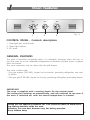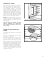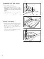
1
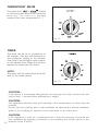
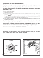
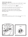
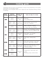
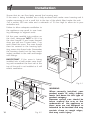
Users Operating Instructions
Installation instructions
Before operating this oven,
please read these instructions carefully
Gas Oven
DGS 61 ST
Introduction
Congratulations on your purchase of this Delonghi Gas Oven which has been
carefully designed and produced to give you many years of satisfactory use.
Before using this appliance it is essential that the following instructions are carefully
read and fully understood.
We would emphasise that the installation section must be fully complied with for your
safety to ensure that you obtain the maximum benefits from your appliance.
Declaration of
CE
conformity
✓ This oven has been designed, constructed and marketed in compliance with:
-
Safety requirements of EU Directive "Gas" 90/396/EEC;
Safety requirements of EU Directive "Low Voltage" 2006/95/EC;
Protection requirements of EU Directive "EMC" 89/336/EEC;
Requirements of EU Directive 93/68/EEC.
GB
Important:
This appliance is designed and manufactured solely for the cooking of domestic
(household) food and is not suitable for any non domestic application and therefore should not be used in a commercial environment.
The appliance guarantee will be void if the appliance is used within a non domestic environment i.e. a semi commercial, commercial or communal environment.
2
BEFORE USING FOR THE FIRST TIME
• Read the instructions carefully before installing and using the appliance.
• After unpacking the appliance, check that it is not damaged. In case of doubt, do
not use the appliance and contact your supplier or a qualified engineer.
• Remove all the packing materials (i.e. plastic bags, polystyrene foam, etc.) and do
not leave it around within easy reach of children, as these may cause serious injuries.
The packaging materials are recyclable.
• Do not attempt to modify the technical characteristics of the appliance, as it may
become dangerous to use.
• The appliance should be installed and all the gas/electrical connections made by a
qualified engineer in compliance with local regulations in force and following the
manufacturer's instructions.
IMPORTANT INSTRUCTIONS AND ADVICE FOR THE USE OF
ELECTRICAL APPLIANCES
The use of any electrical appliance requires the compliance with some basic rules,
namely:
– do not touch the appliance with wet or damp hands (or feet)
– do not use the appliance whilst in bare feet
– do not allow the appliance to be operated by children or unqualified persons
without supervision.
The manufacturer cannot be deemed responsible for damages caused by wrong or
incorrect use.
USING THE OVEN FOR THE FIRST TIME
You are advised to carry out the following operations:
• Assemble the interior of the oven as described under the heading “Cleaning and
maintenance”
• Switch the empty oven ON at maximum temperature for about two hours to eliminate traces of grease and smell from the components.
• Let the oven cool down, switch off the electrical supply, then clean the inside of
the oven with a cloth soaked in water and neutral detergent and dry thoroughly.
3
IMPORTANT SAFEGUARDS AND RECOMMENDATIONS
• Do not carry out any cleaning or maintenance without first disconnecting the appli-
ance from the electrical supply.
• During and after use of the oven, certain parts will become very hot. Do not touch
hot parts.
• After use always ensure that the knobs are in the OFF position.
• Keep children away from the oven during use.
• Do not allow young children or infirm persons to use the appliance without your
supervision.
• WARNING
•
•
•
•
•
•
•
•
•
•
When correctly installed, your product meets all safety requirements laid down for
this type of product category. However special care should be taken around the
rear or the underneath of the appliance as these areas are not designed or intended to be touched and may contain sharp or rough edges, that may cause injury.
Fire Risk! Do not store inflammable materials inside the oven.
Always use oven gloves when removing the shelves and food trays from the oven
whilst hot.
Do not line the oven walls with aluminium foil. Do not place baking trays or the
drip tray on the base of the oven chamber.
Clean the ovens regularly and do not allow fat or oils to build up in the oven base
or trays. Remove spillages as soon as they occur.
Always stand back from the oven when opening the oven door to allow steam
and hot air to escape before removing the food.
Do not hang towels, dishcloths or other items on the cooker or its handle – as
this could be a fire hazard.
Make sure that electrical cords connecting other appliances in the proximity cannot
become entrapped in the oven door.
Before disposing of an unwanted appliance, it is recommended that it is made inoperative and that all potentially hazardous parts are made harmless.
Important: This appliance has been designed for domestic use only. The appliance
is NOT suitable for use within a semi-commercial, commercial or communal environment.
Safe food handling: leave food in the oven for as short a time as possible before
and after cooking. This is to avoid contamination by organisms which may cause
food poisoning. Take particular care during warmer weather.
SAFETY GUARD
The glass on the oven door reaches high temperatures during operation.
For child safety, a door guard can be fitted to prevent contact with the hot glass.
The door guard (kit for installing the 3rd glass on the oven door) is supplied as an
accessory on request. Contact one of our dealers or Service Centre and indicate the
relevant appliance model.
4
1
Oven features
1
2
3
Fig. 1.1
CONTROL PANEL - Controls description
1. Oven/grill gas control knob
2. Oven light selector
3. 60’ timer.
GENERAL FEATURES
The oven is furnished completely clean. It is advisable, however, upon first use, to
turn the oven on to the maximum temperature to eliminate possible traces of grease
from the burner.
The same operation may be done with the grill burner.
The oven is fitted with:
– One gas burner (3,00 kW), located at the bottom, providing self-ignition and safety device
– One gas grill (2,30 kW), placed on the top, providing self-ignition and safety device.
IMPORTANT:
The oven is supplied with a cooling device for the control panel.
The cooling fan switches on automatically, and will continue to run even if
the oven is switched off, until the correct temperature is reached.
During use the appliance becomes hot. Care should be taken to avoid touching heating elements inside the oven.
Attention: the oven door becomes very hot during operation.
Keep children away.
5
THERMOSTAT KNOB
The values from
to
printed
on the facia panel around the thermostat
knob (fig. 1.2) show in a growing
sequence the oven temperature in °C.
Fig. 1.2
TIMER
The timer can be set to a maximum of
60 minutes. Turn the dial clockwise to
the maximum setting of 60 minutes
then turn it anti-clockwise until it reaches the desired time. When the set time
expires the timer bell will sound.
NOTE:
The oven will not switch itself off at the
end of the timed period.
Fig. 1.3
CAUTION:
If the burner is accidentally extinguished, turn the gas off at the control knob and
wait at least 1 minute before attempting to relight.
CAUTION:
Gas appliances produce heat and humidity in the environment in which they are
installed.
Ensure that the cooking area is well ventilated by opening the natural ventilation
grilles or by installing an extractor hood connected to an outlet duct.
CAUTION:
6
If the appliance is used for a prolonged time it may be necessary to provide further ventilation by opening a window or by increasing the suction power of the
extractor hood (if fitted).
LIGHTING OF OVEN BURNER
The thermostatic tap controlling the gas supply to the burner is equipped with a safety device which automatically stops the gas flow in case of flame extinction. The temperature is constantly maintained on the set value.
The electric ignition starts up by pressing the thermostat knob.
A safety device prevents the electric ignition from functioning when the
oven door is shut.
To light the burner, you need to:
1 – Fully open the oven door.
2 – Press the thermostat knob (fig. 1.2) thoroughly to start up the electric ignition and,
keeping the knob under pressure turn it anti-clockwise (fig. 1.4) to position
.
Never continue this operation for more than 15 seconds. If the burner has still
not ignited, wait for about 1 minute prior to repeating the ignition.
To light the oven manually, approach a flame to the hole “A” of the floor (fig.
1.5), then press and turn the thermostat knob.
3 – Wait about ten seconds after lighting the burner to release the knob (priming time
of the thermocouple)
4 – Adjust the thermostat knob on the desired setting.
If the flame extinguishes for any reason, the safety valve will automatically shut off
the gas supply to the burner.
To re-light the burner, first turn the oven control knob to position
, wait for at least
1 minute and then repeat the lighting procedure.
For a correct pre-heating, we suggest to remove tray and shelf from the oven and
introduce them again after 15 minutes.
ATTENTION: In case of manual lighting, never turn the thermostat tap before
approaching a flame to the hole “A” of the floor.
A
Fig. 1.4
Fig. 1.5
7
LIGHTING OF GAS GRILL BURNER
The thermostatic tap controlling the gas supply to the burner is equipped with a
safety device which automatically stops the gas flow in case of flame extinction.
The electric ignition starts up by pressing the thermostat knob.
A safety device prevents the electric ignition from functioning when the
oven door is shut.
To turn on the grill burner:
1) Open the oven door.
2) Press thoroughly and turn clockwise the oven gas thermostat knob fig. 1.6 to set
symbol
.
To light the grill manually, put a flame to the right and left side of the burner for 2-3
seconds after the thermostat has been opened (fig. 1.7).
3) Wait about ten seconds after the burner lighting before releasing the knob (time of
priming of the valve).
Should the flame of the burner extinguish for any reason, the safety valve will cut off
automatically the gas flow to the thermostat.
IMPORTANT: In case of accidental extinction of the burner, turn off the control knob and wait at least one minute before trying to ignite again.
For correct use see chapter “TRADITIONAL GRILLING”.
Remember to keep children away from the appliance when you use the
grill or oven, since these parts become very hot.
Fig. 1.6
8
Fig. 1.7
TRADITIONAL GRILLING
Very important: always use with the door ajar and with shield "A” mounted (Fig. 1.8).
Fit the screen A (Fig. 1.8) which protects the control panel from the heat.
Switch the grill on, setting the knob to position
.
Leave to warm up for approximately 5 minutes with the door ajar.
Place the food inside positioning the rack as near as possible to the grill.
Insert the drip pan under the rack to collect the cooking juices.
The operation of the grill should not exceed 30 minutes.
Attention: the oven door becomes very hot during operation.
Keep children away.
OVEN LIGHT
The oven provides an interior lamp to allow the visual inspection during the cooking.
To light the oven lamp turn the knob fig. 1.9, to the symbol
.
HOT PART
ALLOW TO COOL
BEFORE REMOVING
A
Fig. 1.8
Fig. 1.9
9
2
Cooking guide
Temperature and times given are approximate, as they will vary depending on the quality
and amount of food being cooked.
Remember to use ovenproof dishes and to adjust the oven temperature during cooking
if necessary.
KNOB
SETTING
APPROX.
TEMPERATURE
HEAT OF
OVEN
130°C
(266°F)
Very cool
oven
Meringue
slow cooking foods.
140°C - 145°C
(284°F - 293°C)
Cool or
slow oven
Milk puddings, very rich fruit
cakes, eg., Christmas.
155°C
(311°F)
Cool or
slow oven
Stews, casseroles, braising,
rich fruit cakes, eg., Dundee.
165°C - 170°C
(329°F - 338°F)
Warm oven
180°C
(356°F)
Moderate
oven
Plain cakes, eg., Victoria
sandwich, meat pies.
190°C - 195°C
(374°F - 383°F)
Fairly hot
oven
Small cakes, savoury flans,
fish.
205°C
(401°F)
Hot oven
Plain cakes and buns, swiss rolls,
fruit pies. High temp. roasting.
215°C - 220°C
(419°F - 428°F)
Moderately
hot ovenl
230°C
(446°F)
240°C
(464°F)
10
Very hot
oven
TYPE OF DISH TO COOK
Biscuits, Low temperature roasting,
rich plain cakes eg., Madeira cake.
Bread and bread rolls etc., scones,
flaky and rough puff pastry,
Yorkshire pudding
Sausage rolls, mince pies, puff
pastry.
Browning ready cooked dishes.
Important notes
Installation, and any demonstration, information or adjustments are not included in
the warranty.
This appliance must be installed and serviced only by a suitably qualified and registered person, and in accordance with the current editions of the relevant standards
and regulations or other locally applicable regulations.
Attention
The appliance gets very hot, mainly around the cooking areas. It is very
important that children are not left alone in the kitchen when you are
cooking.
AFTER SALES SERVICE
Should you require to book a service call telephone 0870 5425 425.
For product information and advise telephone 0844 800 9595.
11
Do’s and do not’s
• Do not grill with oven door closed. Always fit the heat shield supplied with the
oven under the front panel before commencing operations.
• Do read the user instructions carefully before using the oven for first time.
• Do allow the oven to heat for one and a half hours, before using for the first time,
in order to expel any smell from the new oven insulation, without the introduction
of food.
• Do clean your oven regularly.
• Do remove spills as soon as they occur.
• Do always use oven gloves when removing food shelves and trays from the oven.
• Do not allow children near the oven when in use.
• Do not allow fat or oils to build up in the ovens trays, or oven base.
• Do not place cooking utensils or plates directly onto the oven base.
• Do not grill food containing fat without using the grid.
• Do not cover the grilling grid with aluminium-foil.
• Do not use the oven tray for roasting.
• Do not place hot enamel parts in water. Leave them to cool first.
• Do not allow vinegar, coffee, milk, saltwater, lemon or tomato juice to remain in
contact with enamel parts (inside the oven and on the oven tray).
• Do not use abrasive cleaners or powders that will scratch the surface of the stainless steel and the enamel.
• Do not attempt to repair the internal workings of your oven.
• Do remove the protective film before the first use.
• Fire risk! Do not store flammable material in the oven.
FOR YOUR SAFETY
The product should only be used for its intended purpose which is for the cooking
of domestic foodstuffs.
Under no circumstances should any external covers be removed for servicing or maintenance except by suitably qualified personnel.
12
3
Cleaning and maintenance
GENERAL ADVICE
– When the appliance is not being used, it is advisable to keep the gas tap closed.
– Every now and then check to make sure that the flexible tube that connects the
gas line or the gas cylinder to the appliance is in perfect condition and get it
replaced if it shows any signs of wearing or damage.
– The periodical lubrication of the gas taps must be done only by specialised personnel.
– If a tap becomes stiff, do not force; contact your local Service Centre.
– Important:
the use of suitable protective clothing/gloves is recommended when handling or cleaning of this appliance.
WARNING
When correctly installed, your product meets all safety requirements laid
down for this type of product category. However special care should be
taken around the rear or the underneath of the appliance as these areas
are not designed or intended to be touched and may contain sharp or
rough edges, that may cause injury.
ENAMELLED PARTS
All the enamelled parts must be cleaned with a sponge and soapy water or other
non-abrasive products.
Dry preferably with a microfibre or soft cloth.
Acidic substances like lemon juice, tomato sauce, vinegar etc. can damage the enamel
if left in contact for too long.
IMPORTANT:
Before cleaning or carrying out any maintenance disconnect the appliance from the electrical supply and wait for it to cool down.
Do not use a steam cleaner because the moisture can get into the appliance thus make it unsafe.
13
STAINLESS STEEL, ALUMINIUM PARTS AND SILK-SCREEN
PRINTED SURFACES
Clean using an appropriate product. Always dry thoroughly.
IMPORTANT: these parts must be cleaned very carefully to avoid scratching and abrasion. You are advised to use a soft cloth and neutral soap.
CAUTION: Do not use abrasive substances or non-neutral detergents as these
will irreparably damage the surface.
GAS TAPS
In the event of operating faults in the gas taps, call the After Sales Service Department.
FLEXIBLE TUBE
From time to time, check the flexible tube connecting the gas supply to the cooker.
It must be always in perfect condition; in case of damage arrange for it to be replaced
by a suitable qualified and registered installer.
REPLACING THE OVEN LIGHT BULB
Switch the oven off at the mains. When the oven is cool, unscrew and replace
the bulb with another one resistant to high temperatures (300°C), voltage 230 V
(50 Hz), E14 and same power (check watt power as stamped in the bulb itself) of the
replaced bulb.
Note: Oven bulb replacement is not covered by your guarantee.
OVEN DOOR
The inside window can be easily
removed fol cleaning by unscrewing
the two fixing screws (Fig. 3.1).
Attention: When cleaning the oven
do not take off the rubber door packing and do not over tighten the fixing
screws when refitting.
14
Do not use harsh abrasive cleaners
or sharp metal scrapers to clean
the oven door glass since they
scratch the surface, which may
result in shattering of the glass.
Fig. 3.1
INSIDE OF OVEN
The oven should always be cleaned
after use when it has cooled down.
The cavity should be cleaned using a
mild detergent solution and warm
water. Suitable proprietary chemical
cleaners may be used after first consulting with the manufacturers recommendations and testing a small sample
of the oven cavity. Abrasive cleaning
agents or scouring pads/cloths should
not be used on the cavity surface.
NOTE: The manufacturers of this appliance will accept no responsibility for
damage caused by chemical or abrasive cleaning.
Fig. 3.2
Let the oven cool down and pay
special attention no to touch the
hot heating elements inside the
oven cavity.
HOW TO USE YOUR GAS
OVEN
Locate the wire side frames as indicated
in Fig. 3.2.
Slide in, on the guides, the shelf and
the tray etc. (Fig. 3.3).
The rack must be fitted so that the safety catch, which stops it sliding out,
faces the inside of the oven (Fig. 3.3).
Before using the oven for the first time,
we recommend that you clean it with
soapy water, rinse carefully and heat for
30 minutes at maximum temperature.
A slightly unpleasant smell may be
produced, caused by grease remaining
on the oven elements from the
production process.
Fig. 3.3
15
DISMANTLING THE DOOR
Please operate as follows:
– Open the door completely.
– Push down the lever L fig. 3.4 and,
keeping it in this position, slowly
close the door in order to block the
hinge.
– Grip the door (as indicated in fig. 3.5)
and, while closing it, release the two
hinges as shown in fig. 3.6.
L
Fig. 3.4
DOOR ASSEMBLY
– Grip the door with your hands placed
near the hinges and raise the levers
H with your forefingers (fig. 3.6)
– Insert the hinges in their position until
levers H are hooked.
– Open the door completely to obtain
the release of levers L.
Fig. 3.5
H
Fig. 3.6
16
Advice for
the installer
IMPORTANT
– This appliance must be installed and serviced only by a suitably qualified and registered person, and in accordance with the current editions of the relevant standards and regulations or other locally applicable regulations.
– The appliance must be installed in compliance with the manufacturer's instructions.
– Always unplug the appliance before carrying out any maintenance operations or
repairs.
– Some appliances are supplied with a protective film on steel and aluminium parts.
This film must be removed before using the cooker.
– Important: the use of suitable protective clothing/gloves is recommended
when handling or installing of this appliance.
17
4
Installation
Ensure that air can flow freely around the housing area.
If the oven is being installed into a fully enclosed built under oven housing unit it
maybe necessary to cut a small slot in the top of the plinth fitted under the unit.
Cut a section 400 mm wide and a minimum of 15 mm high to allow air to pass
underthe unit.
Failure to allow adequate ventilation to
the appliance may result in over heating ordamage to adjacent units.
IMPORTANT: If the oven is being
installed into a built under oven housing unit ensurethat the front rail at the
top of the unit is not installed as it will
restrict ventilation.
560
560
585
Lift the oven carefully into position on
the shelf, takingcare NOT to lift it by
the door handle. If you lower theoven
door, you will see 4 screw holes, 2 on
each sideof the oven. The oven should
then be secured to the housing byfitting screws into these holes. Remember
the housing should not be free standingbut secured to the wall and/oradjacent fittings.
50
Fig. 4.1
594
591
555
.
in
m 50
5
54
594
0
20
18
Fig. 4.2
WARNING
When correctly installed, your
product meets all safety requirements laid down for this type of
product category.
However special care should be
taken around the rear or the
underneath of the appliance as
these areas are not designed or
intended to be touched and may
contain sharp or rough edges,
that may cause injury.
LOCATION
The appliance may be installed in a kitchen, Kitchen/diner or a bed sitting room, but
not in a room or space containing a bath or a shower.
– The appliance must not be installed in a bed-sitting room of less than 20 m3.
– The appliance is designed and approved for domestic use only and should not be
installed in a commercial, semi commercial or communal environment.
– Your product will not be guaranteed if installed in any of the above environments
and could affect any third party or public liability insurances you may have.
PROVISION FOR VENTILATION
✓ The appliance should be installed into a room or space with an air supply in accor-
dance with BS 5440-2: 2000.
✓ For rooms with a volume of less than 5 m3 - permanent ventilation of 100 cm2
free area will be required.
✓ For rooms with a volume of between 5 m3 and 10 m3 a permanent ventilation of
50 cm2 free area will be required unless the room has a door which opens directly to the outside air in which case no permanent ventilation is required.
✓ For rooms with a volume greater than 10 m3 - no permanent ventilation is required.
NB. Regardless of room size, all rooms containing the appliance must have
direct access to the outside air via an openable window or equivalent.
✓ Where there are other fuel burning appliances in the same room, BS 5440-2: 2000
should be consulted to determine the correct amount of free area ventilation requirements.
✓ The above requirements allow also for use of a gas oven and grill but if there are
other gas burning appliances in the same room, consult a qualified engineer.
19
5
Gas installation
IMPORTANT NOTE
This appliance is supplied for use on NATURAL GAS or LPG (check the gas regulation
label attached on the appliance).
✓ Appliances supplied for use on NATURAL GAS: they are adjusted for this gas only
and cannot be used on any other gas (LPG) without modification. The appliances
are manufactured for conversion to LPG.
✓ Appliances supplied for use on LPG: they are adjusted for this gas only and cannot be used on any other gas (NATURAL GAS) without modification. The appliances
are manufactured for conversion to NATURAL GAS.
If the NATURAL GAS/LPG conversion kit is not supplied with the appliance this kit can
be purchased by contacting the After-Sales Service.
INSTALLATION & SERVICE REGULATIONS (UNITED KINGDOM)
It is a legal requirement that all gas appliances are Installed & Serviced by a competent
person in accordance with the current editions of the following Standards &
Regulations or those regulations appropriate to the geographical region in which they
are to be installed:
✓ Gas Safety (Installation & Use) Regulations
✓ Building Regulations
✓ British Standards
✓ Regulations for Electrical Installation
Installation and service of any gas product must be made by a suitably qualified person
competent on the type of product being installed or serviced and holding a valid
certificate of competence for the work being carried out. Currently the proof of
competence is the Accredited Certification Scheme (ACS) or S/NVQ that has been
aligned to the ACS.
It is also a requirement that all businesses or self employed installers are members of a
class of person approved by the Health and Safety Executive.
Failure to install the appliance correctly could invalidate any manufacturers warranty
and lead to prosecution under the above quoted regulation.
20
Gas connection
The installation of the gas appliance to Natural Gas or LP Gas must be carried out
by a suitably qualified and registered installer. Installers shall take due account of the
provisions of the relevant British Standards Code of Practice, the Gas Safety Regulations
and the Building Standards (Scotland)(Consolidation) Regulations issued by the Scottish
Development Department.
Installation to Natural Gas
Installation to Natural Gas must conform to the Code of Practice, etc.
The supply pressure for Natural Gas is 20 mbar.
The installation must conform to the relevant British Standards.
Installation to LP Gas
When operating on Butane gas a supply pressure of 28-30 mbar is required. When
using Propane gas a supply pressure of 37 mbar is required.
The installation must conform to the relevant British Standards.
Warning: Only a suitably qualified and registered installer, also with technical knowledge of electricity should install the appliance. He should observe the Regulations and
Codes of Practice governing such installation of gas appliances.
Note: It is recommended that the gas connection to the appliance is installed with
a flexible connecting tube made to BS5386.
Notes:
✓ Flexible hoses can be used where the sited ambient temperature of the
hose does not exceed 70°C. These hoses must be manufactured in
accordance with BS669 part 1 and be of the correct construction for the
type of gas being used.
✓ Gas hoses designed for natural gas MUST NOT be used for supplying LPG
gas (LPG gas hoses can be identified by a either a red band or stripe on
the rubber outer coating of the hose).
The hose should not be crushed or trapped or be in contact with sharp or
abrasive edges.
21
If installation is to be carried out using a flexible connector (to BS669), then the
following points must be adhered to:
Note: The gas installation pipes and the final connection to the appliance connecting
pipe shall be sufficient size to maintain the heat output of the appliance as specified
under installation.
1. The appliance flexible connector should not be subject to undue forces, either in
normal use whilst being connected or disconnected.
2. The appliance flexible connector should not be subject to excessive heat by direct
exposure to flue products or by contact with hot surfaces.
3. The socket into which the plug of the appliance flexible connector fits should be
permanently attached to a firmly fixed gas installation pipe and positioned such that
the hose hangs freely downwards.
4. The appliance flexible connector should be positioned such that it will not suffer
mechanical damage; eg abrasion from the surrounding kitchen furniture which may
be moved in use, such as a door or drawer, or by being trapped by a stability
device.
5. The plug-in connector should be accessible for disconnection after moving the
appliance.
6. Using a suitable leak detection fluid solution (e.g. Rocol) check each gas
connection one at a time by brushing the solution over the connection.
The presence of bubbles will indicate a leak.
If there is a leak, tighten the fitting and then recheck for leaks.
IMPORTANT!
Do not use a naked flame to test for leaks.
GAS CONNECTION FITTING
Appliance
inlet pipe
Floating nut
1/2” G cylindrical
(male)
Washer
1/2” G cylindrical
(female)
Conical adapter
1/2” BSP
(male)
Fig. 5.1
22
To screw the connecting
tube or the conical adapter
operate with two spanners.
Fig. 5.2
Gas conversion (to L.P.G. or Natural gas)
This appliance is regulated to work with
the gas indicated in the gas regulation
label.
If it has to work with another type of
gas (L.P.G. or Natural gas), before the
appliance is connected you must
substitute the oven and grill burner
injectors as follows:
Fig. 5.3
REPLACEMENT OF THE
OVEN BURNER INJECTOR
✓ Open the oven door completely.
✓ Remove the burner cover (Fig. 5.3).
✓ Remove the burner by unscrewing
the two front screws (Fig. 5.4). Take
care not to damage the wire to the
ignition electrode and the safety
valve probe.
✓ Unscrew the oven burner injector
(Fig. 5.5) using a 7 mm spanner and
substitute it with one of the correct
size. See "TABLE FOR THE CHOICE OF
THE INJECTORS".
✓ Replace all the components by following in reverse the operations
explained above.
Fig. 5.4
Fig. 5.5
23
REPLACEMENT OF THE
OVEN BURNER INJECTOR
✓ Remove the burner by unscrewing
the front screw (fig. 5.6).
Gently suspend the burner as shown
in figure 5.7.
Be careful not to damage the wire of
the electric ignition and the probe of
the safety valve.
✓ Using a 7 mm box spanner, replace
Fig. 5.6
the injector (indicated by the arrow
in fig. 5.7). See "TABLE FOR THE
CHOICE OF THE INJECTORS".
✓ Replace the burner repeating the
above steps in reverse order.
Fig. 5.7
TABLE FOR THE CHOICE OF THE INJECTORS
GB
BURNERS
Cat:
Nominal Reduced
Power Power
[kW]
OVEN
3,000 0,650
GRILL
2,300
* = Reference value
24
[kW]
-
G 30 - 28-30 mbar
G 31 - 37 mbar
II
2H3+
G 20
20 mbar
By-pass Ø injector Ring opening By-pass Ø injector Ring opening
[mm]
[mm]
[1/100 mm] [1/100 mm]
[1/100 mm] [1/100 mm]
42
83
15 *
-
76
fully open*
adjustable
-
125
4 *
115
4 *
FLAME REGULATION OF THE OVEN AND GRILL BURNERS
Using a cross-head screwdriver, slacken the screw securing the air flow regulation collar (figs. 5.8 and 5.9) and move the collar forward or backward to increase or reduce
the air aperture in accordance with gas type and the indications in the “TABLE FOR
THE CHOICE INJECTORS”.
Light the burner and check the flame.
Warning: The regulation of the flames must only be carried out by a suitable qualified
and registered installer.
Fig. 5.9
Ring opening [mm]
Fig. 5.8
Ring opening [mm]
25
REGULATION OF THE MINIMUM FLAME
This needs to be done only for the oven burner (the grill is a fixed capacity) by acting on the thermostat.
Considering that in the minimum position the flame must have a length of about 4
mm and must remain lit even with a brusque passage from the maximum position
to that of minimum.
The flame adjustment is done in the following way:
✓ Light the oven burner by turning the knob on position
.
✓ Let the oven pre-heat for about 10 minutes, then take the knob to position
(minimum) to operate at by-pass flow.
✓ Remove the thermostat knob and by means of a thin screwdriver pass by the hole
in the facia panel to unscrew of 3 turns the by-pass screw G (fig. 5.10)
✓ Slowly tighten the by-pass screw G (fig. 5.10) until you get a flame of 3-4 mm
long.
✓ Turn off the burner and reassemble the knob.
✓ After regulation (always with oven hot and the oven door closed) check the sta-
bility of the flame with a passage from the maximum to minimum position.
The grill is a fixed capacity and does not need be adjusted.
N.B.: For Liquid gas (G 30/G 31) the screw G must be tightened thoroughly.
Fig. 5.10
26
G
6
Electrical section
IMPORTANT: Installation must be carried out according to the manufacturer's
instructions. Incorrect installation may cause harm and damage to people, animals or property, for which the manufacturer accepts no responsibility.
Before carrying out any work on the electrical section of the appliance, it must
be disconnected from the mains.
Connection to a good earth wiring system is absolutely essential.
The manufacturer accepts no responsibility for any inconvenience caused by
failure to comply with this rule.
DETAILS
✓ Connection to the electric power supply must be carried out by a qualified
technician and following the appropriate safety regulations.
✓ Before carrying out the connection to the power supply, the voltage rating of the
appliance (stamped on the appliance identification plate) must be checked for
correspondence to the available mains supply voltage, and the mains electric wiring
should be capable of handling the appliance’s power rating (also indicated on the
identification plate).
Green &
Yellow
Earth
Blue Neutral
3 amp fuse
Brown Live
Fig. 6.1
27
✓ CONNECTION BY A THREE PIN SOCKET (Fig. 6.1)
➜
The appliance must be connected to a 220-240 volts 50 cycle AC supply by
means of a three pin socket, suitably earthed and should be protected by a 3
amp fuse.
➜ If the mains plug is unsuitable for the socket outlet in your home or is removed
for any other reason, then the cut off plug should be disposed of safely to prevent the hazard of electric shock.
➜ There is a danger of electric shock if the cut off plug is inserted into any 13 amp
socket outlet.
✓ CONNECTION USING FIXED WIRING (Fig. 6.2)
➜ It is possible to connect the appliance directly to the mains supply by means of
a heavy duty switch with 3 mm minimum distance between the contacts.
➜ A double pole switch must be provided no further than 2 metres from the appliance to the electrical supply. All supply current and earth conductors must be
able to withstand an ambient temperature of 75°C.
➜ The appliance must be protected by a 3 amp fuse.
DOUBLE POLE SWITCHED
FUSED SPUR OUTLET
FUSE
Fig. 6.2
28
ON
GENERAL NOTES
✓ The wires in the mains lead on this appliance are coloured in accordance with the
following code:
Green and Yellow - Earth
Blue – Neutral
Brown – Live
✓ As the colours may not correspond with the markings identifying the terminals in
your plug or in your spur box, proceed as follows:
➜ The green and yellow wire must be connected to the terminal which is marked
with the letter E or with the earth symbol
or coloured green and yellow.
➜ The blue wire must be connected to the terminal marked N or coloured black.
➜ The brown wire must be connected to the terminal marked L or coloured red.
✓ The power supply cord must not touch against any hot surfaces and must be placed
so that its temperature does not exceed 75°C at any point along its length.
✓ After having installed the appliance, the power switch or power plug must always
be in a accessible position.
✓ The appliance must have its own supply; any other appliances installed near it must
be supplied separately.
✓ N.B. For connections to the mains power supply, never use adaptors, reductions or
multiple power points as these may overheat and catch fire.
✓ In the event that installation should require modifications to the mains supply wiring
system or if the power plug is not suitable for the type of power point available, it
is recommended that a qualified technician be called to carry out substitution. The
technician will also have to verify that the cross-section of the electric cables on the
power point match the appliance’s power rating.
✓ If the supply cord is damaged, it must be replaced by a special cord by a qualified
electrical technician in order to avoid a hazard.
FEEDER SPECIAL CABLE SECTION
Type “H05VV-F”
230 VAC 50/60 Hz
3 x 0,75 mm2
230 V
✓ The supply cable must be replaced with a cable of
the same type.
PE
✓ The electrical cable must be connected to the
terminal board following the diagrams of Fig. 6.3.
L1
N(L2)
Fig. 6.3
29
30
Descriptions and illustrations in this booklet are given as simply indicative.
The manufacturer reserves the right, considering the characteristics of the models described here, at
any time and without notice, to make eventual necessary modifications for their construction or for
commercial needs.
31
Cod. 1103217 - ß3