1
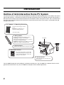
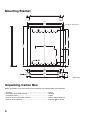
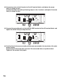
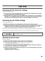
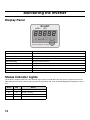
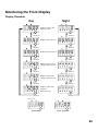
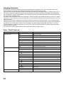
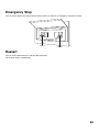
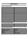
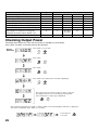
MODEL
JH-1600E
Solar Power Inverter
INSTALLATION &
OPERATION MANUAL
Page
• IMPORTANT SAFETY INSTRUCTIONS ................................ 1
Conventions Used ................................................................... 1
General Safety Precautions for Installation ............................. 1
• Introduction............................................................................ 2
Outline of Grid-Interactive Home PV System .......................... 2
• Dimensions ............................................................................ 3
Solar Power Inverter................................................................ 3
Mounting Bracket..................................................................... 4
Unpacking Carton Box............................................................. 4
• Installation.............................................................................. 5
Planning the Installation .......................................................... 5
Inverter Location...................................................................... 5
• Installing Solar Power Inverter............................................. 6
Mount the Solar Power Inverter............................................... 7
• Wiring Solar Power Inverter ................................................. 9
Before wiring.......................................................................... 10
Removing the Front Panel..................................................... 11
Solar Power Inverter Wiring Overview................................... 12
• Connecting to DC Disconnect............................................ 13
• Connecting to AC Disconnect............................................ 15
• Test Run ............................................................................... 18
Checking the PV Array DC Voltage....................................... 18
Checking the AC Utility Voltage............................................. 18
Starting Up the Inverter ......................................................... 18
• Monitoring the Inverter ....................................................... 19
Display Panel......................................................................... 19
Status Indicator Lights ........................................................... 19
Monitoring the Front Display.................................................. 20
Emergency Stop .................................................................... 22
Restart ................................................................................... 22
• Specification ........................................................................ 23
Electrical Specification........................................................... 23
Environment Specification ..................................................... 23
Mechanical Specification ....................................................... 23
How to Set Parameter ........................................................... 24
Checking Output Power......................................................... 25
WARRANTY
Grid Inverter
This Sharp product is warranted against faults in materials and manufacture for a period of sixty
(60) months from the date of original purchase.
Such faults will be rectified by Sharp Corporation free of charge by either repair or replacement
at Sharp's option when used under normal use and reasonable care in the opinion of Sharp in
accordance with the manufacturers instructions.
Sharp Corporation Australia Pty Ltd is not responsible for the costs of any on-site labor and any
costs associated with the installation, removal, reinstallation or transportation costs under this
limited warranty or for losses due to down time.
THE WARRANTY IS SUBJECT TO:
The unit is installed according to the "Installation Instructions" provided by Sharp.
That the solar power inverter is installed by a licensed electrical contractor in accordance with
AS/NZS 5033 Installation of photovoltaic arrays and AS/NZS 3000 Electrical Installations and
applicable local electrical service rules.
THIS WARRANTY DOES NOT APPLY:
If the rating plate has been removed, damaged or rendered illegible.
The warranty does not extend to accessories, defects or injuries caused by or resulting from
causes not attributed to faulty parts in the manufacture of the product, including but not limited
to defect or injury caused by or resulting from, misuse, abuse, neglect, accidental damage,
improper voltage, incorrect system design, vermin infestation, storm damage, fire, flood,
exposed to corrosive conditions, or any alterations made to the product which are not
authorized by Sharp.
Please retain your sales documentation as this should be produced to validate a
warranty claim.
This warranty is in addition to and in no way limits, varies or excludes
any express and implied rights and remedies under relevant legislation
in the country of sale.
IMPORTANT NOTICE: This warranty applies only to products sold in Australia & New Zealand
FOR LOCATION ENQUIRIES WITHIN
FOR LOCATION ENQUIRIES WITHIN
AUSTRALIA
NEW ZEALAND
REGARDING YOUR LOCAL
REGARDING YOUR LOCAL
SHARP APPROVED SERVICE CENTRE
SHARP APPROVED SERVICE CENTRE
VISIT OUR WEBSITE AT
VISIT OUR WEBSITE AT
www.sharp.net.au
www.sharp.net.nz
OR CALL SHARP CUSTOMER CARE
CONTACT YOUR SELLING DEALER/RETAILER
OR CALL
1300 135 022
SHARP CUSTOMER SERVICES
(LOCAL CALL COST APPLY WITHIN AUSTRALIA)
TELEPHONE: 09 573 0111
FACSIMILE: 09 573 0113
SHARP CORPORATION OF AUSTRALIA PTY LTD
SHARP CORPORATION OF NEW ZEALAND LIMITED
IMPORTANT SAFETY INSTRUCTIONS
SAVE THESE INSTRUCTIONS
This manual contains important safety instructions that shall be followed during the installation and maintenance of the
solar power inverter.
To reduce the risk of electrical shock, and to ensure the safe installation and operation of the solar power inverter, the
following words appear throughout this manual to inform you of or alert you to something that may cause a dangerous
situation or that safety instructions must be followed.
Conventions Used
The following conventions are used in this guide.
May cause serious injury or death unless the instructions are followed.
May injure a person or damage equipment unless the instructions are followed.
Important information to be followed when installing or using the solar power inverter.
General Safety Precautions for Installation
• This solar power inverter must be installed by a licensed electrical contractor in accordance with:
a) AS/NZS 5033 Installation of photovoltaic (PV) arrays
b) AS/NZS 3000 Electrical Installations (know as the Australian/ New Zealand Wiring Rules
c) Applicable local electrical service rules.
• Installation by a non licensed person is against the law, and could cause electric shock or severe injury if installed incorrectly.
Additionally, your insurance policies and manufacturers warranty will become void and the manufacturer will not liable for any
claims.
• Correct installation will assist the maximum amount of electricity to be exported to the grid.
• To avoid electric shock or burns, always follow all warnings and cautions marked on the solar power inverter, and in this manual.
• Ensure that all electrical connections are secure, loose connections can cause overheating, smoke and fire.
• This solar power inverter is a grid connect device only, it is not intended for stand alone operation.
• Ensure that the AC and DC isolation is switched off before connecting/ disconnecting the inverter.
• The surface of the inverter case can become hot during normal operation. In extreme conditions, the inverter chassis can reach
temperatures of up to 70°C. To avoid accidental burns;
ensure that the inverter is not within reach of children.
do not install it in a location where people can accidentally come into contact with the unit.
• Install the unit according to the installation instructions paying particular attention to clearances for free air circulation. Installing
this device in improper locations may cause overheating, smoke and fire.
• Do not cover or impede the free air flow around the unit, this may cause overheating and reduced performance.
• Do not disassemble or attempt to repair the unit, disassembling the unit will break the seal and void the manufacturer's warranty.
• Do not install the unit on an external wall near the ocean, salt air can cause corrosion.
• The inverter does not contain DC or AC isolation switches, these should be provided by the installer.
1
Introduction
Outline of Grid-Interactive Home PV System
The home PV system is a grid connected type product that includes the following components: PV modules that convert
light into DC electricity, a solar power inverter that changes DC electricity into AC and blends the power with the utility, a
DC disconnect that breaks the connection between the PV modules and the solar power inverter, and an AC disconnect
that breaks the connection between the load center and the solar power inverter. The system is connected to the grid
through the AC meter.
1. PV* Module / 2. Mounting Structure
Converts solar energy to electric
power.
PV modules are fixed on roof
with the mounting structure.
*PV: Photovoltaic
3. Wiring Cables
Connect PV array and the DC disconnect.
PV String: A number of PV modules
interconnected electrically in series to produce
the required operating voltage.
PV Array: A number of PV modules connected
together in a single mounting structure.
4. DC Disconnect
PV String
1
2
PV Arr
ay
Grid
Isolates the PV array from the solar power inverter.
3
5. Solar Power Inverter
6
The solar power inverter converts DC
power generated by PV array into AC
power, and automatically controls the
operation of the system.
JH-1600E
AC r
Mete
5
Solar
Powe
Invertr
er
ttWa
r
hou r
Mete
4
6. AC Disconnect
Isolates the AC power from the solar
power inverter.
The JH-1600E incorporates anti-islanding in accordance with AS 4777. The JH-1600E has a detector circuit to sense
ground faults from the PV array. The JH-1600E also complies with local EMC requirement.
2
Dimensions
440±5
408
Solar Power Inverter
348
141
(Unit: mm)
3
Mounting Bracket
347
330
EXTRUDE M5xP0.8-4PL
60
60
60
60
60
330
405.6
199.5
60
60
60
40.5
174.5
174.5
180
25
287
12
52
293
303
47
25
(Unit: mm)
Unpacking Carton Box
Before installation, make sure all the items listed below are included within the carton box.
•
•
•
•
•
Bracket ......................................................................................1 piece
Installation & operation manual.................................................1 manual
Inspection report .......................................................................1 report
Screws (for the solar power inverter) ........................................2 pieces (#6-32 UNC*10)
Screws (for the bracket) ............................................................10 pieces ( 5.5*1.8*80)
4
Installation
Planning the Installation
The following issues need to be considered when planning for an installation using the inverter. See the specified
sections for detailed.
- Inverter Location (Page 5)
- Installing Solar Power Inverter (Page 6)
- Wiring Solar Power Inverter (Page 9)
Preparing for the Installation
Ensure your electricity provider is consulted for any requirements for connecting to or returning power to the grid. Obtain
all permits necessary to complete the installation. Consult your local and national electrical codes for more information.
Inverter Location
The solar power inverter should be installed outdoors except near salt water*. Installation of this device in an improper
location may cause smoke or fire danger. Also refer to the IMPORTANT SAFETY INSTRUCTIONS section on page 1.
For best performance, the inverter should be installed in a cool shady area.
Do not install the solar power inverter in a location:
• Higher than the altitude of about 2,000 m above sea level
• Close to corrosive gas or liquid
• Near salt water*
• Exposed to direct sunlight
• Prone to flooding or high levels of snow pack
• Minimal or no air flow, high humidity or condensation
• Near television antenna or antenna cable
* Salt water: area near the ocean or sea, or less than 0.3 miles from the ocean or sea.
Fire Safety
Do not install anywhere near combustible or flammable materials.
Indoor/Outdoor Orientation
The inverter uses a Type IP65-rated enclosure that can be mounted indoors or outdoors.
The inverter must be mounted vertically on a wall or pole.
Do not mount the inverter horizontally.
Temperature
Ensure that the inverter is mounted in a location where the ambient temperature range is -20°C to +60°C. When the
temperature is over +40°C, the inverter may de-rate power.
5
Installing Solar Power Inverter
WARNING: BURN HAZARD
Do not install in a location where people can accidentally come into contact with the inverter.
High temperatures can be present on the inverter, causing a potential burn hazard.
In extreme condition, the inverter chassis can reach temperatures about 70°C, which can cause skin burns
if accidentally touched. Ensure that the inverter is located away from normal traffic areas.
Inverter failure due to improper installation will void the inverter warranty.
Consider the following when determining where to install the inverter.
• Excessive debris (such as dust, leaves and cobwebs) can accumulate on the unit, interfering with
wiring connections and ventilation. Do not install in a location where debris can accumulate (under
a tree, for example).
• Make sure that the wall is strong enough to handle the weight of the solar power inverter. Reinforce
the wall as required for a secure installation.
• Make sure that ventilation of the solar power inverter is unobstructed. Keep the clearance on the
upper of the solar power inverter more than 300 mm, the lower more than 500 mm and the left and
right sides more than 150 mm each.
• Make sure that the lower side of the solar power inverter has 1500 mm and the front side has 700
mm clearance for the electrician to operate.
• Make sure that the solar power inverter is installed plumb and level.
• Never install the solar power inverter upside down.
• Never install the solar power inverter horizontally or tilted.
To minimize copper losses, the wire lengths between the PV array and the inverter and between the
inverter and the Main Utility Service Panel are kept to a minimum.
The maximum distances will depend on wire gauges and the PV array output voltages.
Eaves
more than 300 mm
more than 150 mm
AC
Disconnect
more than 150 mm
Solar
Power
Inverter
AC meter
Eaves
DC
Disconnect
more than 500 mm
PV Array
more than 300 mm
more than
700 mm
more than 1500 mm
more than 1500 mm
Ground
6
Solar
Power
Inverter
Mount the Solar Power Inverter
Make sure the supporting surface is strong enough to handle 50 kg.
Wall Mount Bracket Dimensions
The dimensions of the mounting bracket are shown in figure below.
120
60
196
60
60
120
40.5
134
180
60
(Unit: mm)
(1) Use 10 pcs screws ( 5.5*1.8*80) to fix the mounting bracket.
Wall
(2) Seal the space between the bracket and the wall with cauking as shown the picture
below.
Sealing
Sealing
Sealing
7
(3) Place the JH-1600E on the mounting bracket. Key holes located on the upper side and
middle side of the inverter unit are for hanging the unit on the bracket. place key holes
on the 4 hexa bolt head the bracket.
(4) Use 2 pcs screws to fix the JH-1600E on the mounting bracket.
(Front)
8
Wiring Solar Power Inverter
• All of the procedure must be completed by a qualified electrician.
• Wiring the solar power inverter and the DC disconnect enclosure must be performed using electrical
conduit.
• Completely cover the surface of the entire PV array with an opaques (dark) material before wiring the
solar modules. The PV array produces electrical energy when exposed to sunlight and could create a
hazardous condition.
• To reduce the risk of electrical shock, do not work with wet hands when your body is wet, or in a wet
location.
• Use low-voltage insulating gloves.
• Disconnect the PV array output cable and the module output cable when working, or wear electrical
insulated clothing.
• To reduce the risk of electrical shock, be sure to turn off the following devices before starting wiring
installation:
- The dedicated circuit breaker for the solar power inverter on the AC meter.
- The DC disconnect switch
- The AC disconnect switch
• Do not turn on the DC and AC disconnect switch until the wiring installation is finished.
• Unused cable opening must be covered.
• Grounding installation is the responsibility of the installer.
• To avoid the risk of fire or electrical shock, use proper sized wires.
• To reduce the risk of short circuits during installation or servicing of the solar power inverter, use
insulated tools.
• All electrical installations shall be done in accordance with all local electrical codes and the Australia
Standards.
• Wiring the PV module
- The number of PV modules in series should be determined so that the open circuit voltage of the
PV strings is not higher than 350 VDC when the ambient temperature is from -20°C to 40°C, and the
minimum operating voltage is higher than 60 V. Refer to the PV manufactures module
specifications for voltage/temperature co-efficient.
• Confirm that the dedicated breaker for the solar power inverter on the AC meter and the breaker on
the AC disconnect are OFF. If they are ON, turn them OFF.
9
Before wiring
AC Circuit breaker
This breaker must be sized to handle the rated maximum output voltage and current of the inverter. (Please refer to the
Specification section on page 23.)
Recommended AC circuit breaker:
For JH-1600E: 10 Amps / 250 VAC.
To wire the main utility service panel to inverter:
(1) Connect the ground wire (green and yellow) from the ground terminal in the main utility
service panel to GND ( ) terminal in the inverter.
(2) Connect the L (or Line) to Line terminal in the inverter.
(3) Connect the N (or Neutral) to Neutral terminal in the inverter.
(4) Ensure all connections are correctly wired and proper torque according to values
shown in the table below.
Wire Size (mm2)
Up to 4
DC cables, isolator fuse
AS per AS/NZS 5033
10
Torque
In-lb
Nm
12
1.3
Removing the Front Panel
Remove the front panel of the solar power inverter.
(1) Remove the 4 screws from the lower part of the front panel of the solar power inverter.
Then remove the front panel.
Screws
Screws
(2) The four glands shown below should be used for the purpose indicated. If there are any
unused or open glands, they should be covered.
AC Disconnect
DC Disconnect
(PV Strings)
(Front)
11
Solar Power Inverter Wiring Overview
WARNING: FIRE, SHOCK AND ENERGY HAZARD
Before wiring the inverter, read all instructions and cautionary markings located in this manual,
on the PV array, and on the main service panel.
CAUTION: Note the polarity of PV cable
Black wire = Positive
White wire = Negative
General wiring steps
There are four main steps in the wiring of the inverter:
(1)
(2)
(3)
(4)
Grounding the PV array (see your PV equipment documentation)
Turning off the DC disconnect and the AC disconnect
Making the DC connections from PV array to the inverter
Making the AC connections from inverter to main utility service panel
SHARP Solar Power Inverter
Utility Grid
Utility Meter
DC connections
AC connections
L
L
Neutral
AC disconnect
DC disconnect
GROUND
Solar Array
12
Connecting to DC Disconnect
Make sure DC disconnect is open.
This section describes the connection between the solar power inverter and the DC disconnect from the PV string.
DC terminal block for DC disconnect
Follow all WARNING and CAUTION of Wiring Solar Power Inverter (page 9).
(1) Install two copper wires (positive and negative) from the DC disconnect through the
conduit.
(2) Attach a forked spade or lug connector to the cables before connecting to the terminal
block.
Pass the wire through the gland before connecting to the terminal.
13
(3) Connect the black wire to the positive terminal of the terminal block, and tighten the
screw firmly to clamp the wire.
(4) Attach a forked spade or lug connector to the cables before connecting to the terminal
block.
(5) Connect the white wire to the negative terminal of the terminal block, and tighten the
screw firmly to clamp the wire.
(6) Confirm all of the wires are correctly and securely connected to the terminals of the
solar power inverter.
WARNING: SHOCK HAZARD
The inverter must be grounded by connection to a grounded permanent wiring system.
14
Connecting to AC Disconnect
This section describes the connection between the solar power inverter and the AC disconnect. The wires needed are
the AC output cable from the solar power inverter (one pair of wires) and the grounding wire.
Follow all WARNING and CAUTION of Wiring Solar Power Inverter (page 9).
• Make sure AC disconnect is open.
• Use outdoor wiring and conduit on the outdoor section between the solar power inverter and
the PV modules.
• The AC disconnect includes over current protection.
GND terminal
AC terminal block for AC disconnect
(1) Attach a forked spade or lug connector to the AC cables before connecting to the
terminal block.
Pass the wire through the gland before connecting to the terminal.
15
(2) Connect one wire to the N terminal of the AC terminal block, and tighten the screw
firmly to clamp the wire.
Connect the other wire (after performing step 2) to the L terminal, and tighten the screw
firmly to clamp the wire.
N
L
(3) Connect the grounding wire to the leftmost GND terminal of the AC terminal block, and
tighten the screw firmly to clamp the wire.
GND
(4) Confirm that all wires are correctly and securely connected to the terminals of the solar
power inverter.
Confirm that all the screws do not move if the connected wires are pulled or bent.
Tighten all the screws firmly again.
16
Test Run
Checking the PV Array DC Voltage
To check the PV array DC voltage:
(1) Uncover the PV arrays and expose them to full sunlight. The sunlight must be intense
enough to produce the required output voltage.
(2) Measure the PV array open circuit DC voltage across the DC positive (+) and negative (-)
terminals. This voltage must greater than 70 VDC (to energize the electronics) and less
than 320 VDC (should be less than 350 VDC to prevent damage to the inverter).
Checking the AC Utility Voltage
To check the AC utility voltage:
(1) Switch on the main and inverter breakers in the main electrical service panel.
(2) Using an AC voltmeter, measure the AC open circuit utility voltage between L (Line) and
N (Neutral). Ensure the voltage is at approximately the nominal value. The inverter
operates with a line-to-neutral voltage range around the nominal value.
See "Output" section in "Electrical Specification" (page 23) for the utility voltage operating range for your inverter model.
After performing the voltage checks, reattaching all covers that were removed during installation and startup.
WARNING: SHOCK HAZARD
Before reattaching covers, turn OFF the breaker switches in the main utility service panel and
disconnect device for PV array.
Starting Up the Inverter
To start up the inverter:
(1) Switch the AC disconnection switch (breaker) to the ON position.
(2) Switch the DC disconnection switch (breaker) to the ON position.
• The inverter starts up automatically.
• It takes approximately 1 minute to startup ON-Grid LED (Green) flashes.
(3) Check the inverter display. After startup is completed, ON-Grid LED (Green) lights up
and output power is displayed on the display panel.
(4) Replace the front panel, pressing up the panel to fit it to the packing (push front panel
up to seal and insert screw).
Tightening torque 6 in-lb (0.7 Nm)
18
Monitoring the Inverter
Display Panel
ON-GRID
W
FAULT
Wh/D kWh
VDC
VAC
Hz
SELECT
SOLAR INVERTER JH-1600E
ON-GRID LED (Green)
Flashing = Standby On = ON-Grid
Fault LED (Red)
Fault condition (please see more detail in Error / Fault Code list.)
W LED (Yellow)
Displays instantaneous power (watts)
Wh/D LED (Yellow)
Displays watt-hours today
kWh LED (Yellow)
Displays total kilowatt-hours
VDC LED (Yellow)
Displays input PV array voltage instantaneously
VAC LED (Yellow)
Displays output utility voltage instantaneously
Hz LED (Yellow)
Displays output utility frequency instantaneously
SELECT button
Press to cycle through W, Wh/D, kWh, VDC, VAC, Hz
Status Indicator Lights
The inverter is equipped with two status indicator lights (LEDs) located above the front panel 7 segment LED. These
LEDs indicate the inverter current status (the table shown below) and assist in troubleshooting the performance of the
unit.
Green
Red
Flash
Off
Standby - reconnecting
On
Off
ON-Grid - operating
Off
On
Fault condition - check code
Off
Off
Sun is down, low DC, no operation
19
Means
Monitoring the Front Display
Display Flowchart
Day
Night
Displays output power
instantaneously.
Press
"SELECT".
Press
"SELECT".
Displays today watt-hour.
Press
"SELECT".
Press
"SELECT".
Displays life kilowatt-hour.
Press
"SELECT".
Press
"SELECT".
Displays input PV array
voltage instantaneously.
Press
"SELECT".
Press
"SELECT".
Displays output utility
voltage instantaneously.
Press
"SELECT".
Press
"SELECT".
Displays output utility
frequency
instantaneously.
Press
"SELECT".
Press
"SELECT".
Flash (1 Hz)
Count down
Error occurred
20
Islanding Protection
The inverter will shut down when the power from the grid becomes abnormal or fails. This will provide safety to the
people working on the power lines and protect the home circuits and solar power inverter.
The solar power inverter continually monitors the voltage and frequency of the grid through an internal control circuit. It
will detect an abnormal condition or failure of the grid. Abnormal conditions include AC overvoltage, AC undervoltage,
AC overfrequency, and AC underfrequency. The solar power inverter shuts down and disconnects from the grid should
any of the above conditions occur.
Per AS 4777, the solar power inverter will stop within 2 seconds should the grid voltage be lower than 210 VAC or higher
than 255 VAC. The solar power inverter will stop within 1 second should the frequency of the grid be lower than 47 Hz or
higher than 53 Hz.
The solar power inverter incorporates two functions to detect and prevent islanding operation. This is important when
the output of the inverter and the power consumption of the home are well balanced and the voltage or the frequency of
the grid does not change during a power failure, resulting in the power failure not detected. If this occurs, a passive
system that detects a jumping voltage phase and an active system that detects frequency shift that stops the inverter
operation within 2 seconds.
The solar power inverter display indicates utility abnormal to indicate a power failure.
Error / Fault Code List
Type
Utility abnormal
Code
F-00
Utility over-voltage
F-01
Utility under-voltage
F-02
Utility frequency over
F-03
Utility frequency under
F-06
Anti-islanding (frequency over)
F-07
Anti-islanding (frequency under)
F-08
Miss utility synchronal lock signal
F-09
Freq. abnormal (50<->60 Hz)
PV array abnormal
PV array under voltage (<60 V)
P-11
Inverter abnormal
EEPROM
21
Items
PV array over voltage (>320 V)
E15
d-15
Relay sticking
E16
d-16
Communication error
E17
d-17
Aux-power abnormal
E18
Ground fault
d-20
Temperature sensor broken
E21
d-21
Output over current
E22
d-22
DC offset over rating
E23
d-23
Fin high temperature
E26
d-26
DC/DC converter abnormal
E27
d-27
Relay open
E28
DC bus voltage abnormal
d-40
EEPROM abnormal
Emergency Stop
Turn off the AC disconnect and the DC disconnect when you execute an emergency stop of the inverter.
DC disconnect
AC disconnect
Turn off
Turn off
Restart
Turn on the AC disconnect first, and then DC disconnect.
The inverter restarts automatically.
22
Specification
Electrical Specification
Input
Absolute maximum array open circuit voltage
JH-1600E
350 VDC
Start voltage
Above 70 VDC
Input voltage, operation voltage range
60~320 VDC
Input voltage, MPPT voltage range
60~320 VDC
Input voltage, Maximum power point range*
200~320 VDC
MPPT tracker
1
Maximum input current
8.5 A
Standby mode (In night or No DC power)
230 VAC, 50 Hz, 0.16 A, 1 Watt max.
Output
JH-1600E
1600 W
Maximum output power
Nominal output voltage
230 VAC
Operating range, utility voltage
210~255 VAC
Nominal output frequency
50 Hz
Operating range, utility frequency
47~53 Hz
Nominal continuous output current
7A
Maximum continuous output current
7.6 A
Output over-current protection
10 A
Maximum utility backfeed current
0A
Total current harmonic distortion
<5%
Power factor
>0.99
Utility monitoring - islanding protection
VAC, Fac as per AS 4777.2
Output characteristics
Current source
Output current waveform
Sine wave
Environment Specification
Operating temperature range
-20°C~60°C (derating at 40~60°C)
Storage temperature range
-20°C~60°C
Relative humidity
5%~90%
Audible noise
<29 dB-A (1m forward front panel)
Operating elevation
0~2000m (0~6666ft)
Mechanical Specification
JH-1600E
Outdoor enclosure
Main body IP65 wiring box IP55
Dimensions - without wall mount (H*W*D / mm)
440*348*141 mm
Dimensions - with wall mount (H*W*D / mm)
440*348*153 mm
Shipping dimension (H*W*D / mm)
515*450*290 mm
Inverter weight
12 kg
Shipping weight
15.5 kg
Input connection
From AWG #16 to AWG #10
Output connection
From AWG #16 to AWG #10
23
Setting item
Setting code
Parameter
Utility over-voltage parameter (V)
1
250
255
260
---
Utility under-voltage parameter (V)
2
205
210
215
---
Over-voltage /Under-voltage settling time (Sec)
3
1.0
1.4
1.8
---
Utility frequency over parameter (Hz)
4
52
53
54
---
Utility frequency under parameter (Hz)
5
46
47
48
---
Utility frequency over/under settling time (Sec)
6
1.0
1.4
1.8
---
Protection timer (Sec)
7
10
60
150
300
Option
*This setting is not used. Do not change the
parameter (Leave the value as default of "5").
8
5
One thing
at a time
31
---
Operating frequency (Sec)
9
50
60
---
---
Checking Output Power
The output power of the last 7 days (the current day is included) can be checked.
Press "ENT" and "SEL" in the front panel for the operation.
Press "ENT" for 5 seconds.
Normal
operation
SEL
ENT
Press "SEL".
SEL
ENT
Press "SEL".
SEL
ENT
Press "ENT". The output power of the day is displayed.
SEL
ENT
The output power goes back one day as "SEL" is pressed.
The display returns to the current day by pressing "SEL"
after output power of 6 days ago is displayed.
SEL
ENT
After checking is finished, press "ENT" to display "dAY-P". Then switch displays until "OFF" is displayed.
After "OFF" is displayed, press "ENT" for 5 seconds.
Press "ENT" for
5 seconds.
25
ENT
Memo
26
1 Huntingwood Drive, Huntingwood, NSW 2148.
by phone on: 1300 135 022
or by fax on: 1300 727 717
WEB site
http://www.sharp.net.au/
TiNSJ0546SNZZ