1
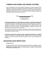
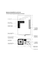
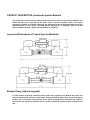
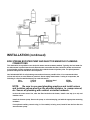
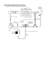
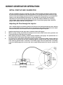
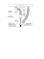
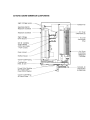
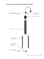
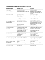
INSTALLATION AND OWNER’S MANUAL
Corona Discharge
CD10/AD
Ozone generator
IMPORTANT SAFETY INSTRUCTIONS
1.
PLEASE FOLLOW ALL INSTALLATION INSTRUCTIONS.
2.
A licensed, qualified electrician should make all electrical connections.
3.
Before attempting any electrical connections, be sure all power is off
at the main circuit breaker.
4.
Install the ozone generator at least five feet from the water using
nonmetallic plumbing.
5.
Install the provided ozone check valves to prevent water from
contacting the electrical equipment.
6.
The electrical supply for this product must include a suitably rated
switch or circuit breaker to open all ungrounded supply conductors to
comply with Section 422-20 of the National Electrical Code, ANSI/N
FPA 70-1987. The means of disconnecting the equipment must be
readily accessible to the operator(s) but installed at least five feet from
the water.
7.
Ambient temperature around the equipment should be between 400
and 1000F (4.5 to 380C). If the equipment is installed in an environment
with temperatures over 1 000F, additional air cooling must be provided.
Installation without additional air cooling in an environment where
temperatures exceed 1000F for any continuous 24 hour period will void
the warranty.
8.
The system should be sized appropriately for its intended use by a
qualified professional familiar with the application. The manufacturer
for its intended use must validate this equipment.
9.
SAVE THESE INSTRUCTIONS.
CORONA DISCHARGE (CD) OZONE SYSTEMS
Ozone is manufactured in the CD ozone generator by drawing in air, which is composed of 20%
oxygen (02), and exposing it to multiple high voltage electrical discharges. This causes the oxygen
molecules to dissociate and reassemble as ozone (03). The ozone is drawn into the water by an
injector/mixer, killing any bacteria, viruses or mold spores it contacts. Ozone is generated on-site,
eliminating the need to store toxic and corrosive chemicals. The corona discharge method is the
most efficient way to produce large amounts of ozone.
3-02
2-03
Chemical Formula for
Corona Discharge Ozone
•
Advanced Water Engineering, Inc. Tech manufactures high output corona discharge systems capable
of producing enough ozone to substantially reduce the consumption of other chemical disinfectants.
This reduction will make the water crystal clear and rainwater soft while allowing for cost savings on
chemicals and maintenance. Also, important health advantages will be realized, including no hair
discoloration, excessive skin dryness, faded swimming apparel, or irritation to the eyes, nasal
passages and throat. Ozone reacts to waterborne contaminants significantly faster than other
disinfectants and the primary by-product is pure oxygen.
•
Advanced Water Engineering, Inc. ozone systems are built with the finest components available. All are
air-cooled and use a venturi injection system to create the best possible contact and mixing of ozone
while maintaining a high level of safety.
•
In contrast to ultraviolet ozone generators, corona discharge systems produce a much higher
concentration of ozone and in much larger quantities. In addition, the annual expense of replacing
lamps and checking ballasts is unnecessary with corona discharge systems. Corona discharge ozone
generation is the most economical and effective method to use on large, commercial water
applications.
UNCRATING AND INSPECTION
Freight Inspection
All equipment should be thoroughly inspected immediately upon delivery. If any damage is noticed,
promptly notify the freight line and request an on-site inspection. Thoroughly inspect all packing
materials prior to discarding. Inspect all plumbing fittings and tubing for packing material
inadvertently lodged in any openings.
PRODUCT DESCRIPTION
The Advanced Water Engineering, Inc. corona discharge ozone system consists of two main components:
• Ozone Generator with built-in Air Preparation
• Venturi Injector Manifold
Ozone Generator
The ozone generator houses the ozone reaction chamber, power supply and all electrical components
directly related to the production of ozone. Ozone is produced when the feed gas is exposed to a high
voltage electrical current inside the reaction chamber.
Air Preparation
The Advanced Water Engineering, Inc. CD10/AD ozone system is equipped with a heat regenerative
desiccant air dryer built into the same enclosure. Corona discharge ozone generators are much more
effective, produce more ozone and require far less maintenance if an air preparation unit is included. The
air preparation system lowers the dew point of the feed gas. Moist feed gas (air) will cause nitric acid to
form inside the generator, which decreases ozone production and if not removed, causes corrosion and
eventual failure of the generator’s internal components. The ability of the ozone generator to produce
0
ozone is drastically reduced as the dew point rises above -55 C. The air dryer desiccant material has an
average life expectancy of five years under normal use.
PRODUCT DESCRIPTION (continued) Injector Manifold
The ozone gas is injected into the filtered water return line by means of the injector manifold. This
allows the ozone to be injected into the water under a vacuum condition, which is the safest
technology available. The injector sizing will vary depending on the flow characteristics of the job.
Atypical injector is shown below. The #978 injector manifold fits 1” plumbing, while the #1 584
injector manifold handles a higher flow rate and fits 2” plumbing.
Layout and Dimensions of Typical Injector Manifolds
Booster Pump (optional upgrade)
it is the booster pump that creates the side stream ozone injection loop. Without this pump, the
main circulation pump could he overburdened, slowing the filtered water return and decreasing the
turnover rate. The booster pump operates all the ozone mixing/injection equipment and enhances
the turnover rate. We recommend the use of a booster pump with systems having a marginal flow
rate.
INSTALLATION
Placement of Equipment
Select a location for the ozone equipment that is as close as possible to the ozone injection point. Situate
the unit in a manner suitable for convenient electrical access. The CD1 0/AD enclosure is not rain proof, so
it is important to choose a location that will keep the system away from direct weather and excessive heat.
Four mounting holes are located on the back of the ozone generator for convenient wall mounting.
Mounting hardware is not provided.
There are two basic installation methods for the CD1 0/AD system: “Full Flow”, where the ozone is injected
directly into the main water return flow, and “Side Stream”, which requires a booster pump on a new,
separate side stream plumbed off of the main water return line. The side stream plumbing is dedicated to
the ozone system only. Follow the instructions below for the alternative you will be using:
FULL FLOW INJECTOR MANIFOLD PLUMBING CONNECTIONS
Refer to the ‘Full Flow Installation’ diagram and follow the instructions below if the ozone is being injected
directly into the lull flow of the pool’s return line:
1.
2.
Tap into the return line after the pump, filter and heater. The ozone injection point should be the last
component in line and as far as possible from the injection point of the residual chemical.
Glue in the proper injector, noting the direction of flow (indicated by an arrow on the injector).
Once the injector is installed, the vacuum may be adjusted as described in the ozone operation
Section.
FULL FLOW OZONE INSTALLATION
INSTALLATION (continued)
SIDE STREAM BOOSTER PUMP AND INJECTOR MANIFOLD PLUMBING
CONNECTIONS
This alternative set up utilizes a two-inch side stream ozone treatment method. Typically, the feed water for
the side stream is pulled from the main filtered water return after the filter, before the heater and returned
at a point after all other equipment and before the residual chemical injection point. The pH adjustment
point will always be the last item in this sequence.
Use Schedule 80 PVC for all plumbing connections whenever possible. Also, it is recommended that
unions and valves are used wherever practical. Ozone rapidly deteriorates a variety of compounds; the
following is a list of materials that may be used with ozone:
Viton
Teflon®
Stainless Steel
EPDM
Silicon
Kynar®
Concrete
Hepalon
NOTE:
Be sure to use good plumbing practices and install unions
and isolation valves wherever the situation dictates, i.e. pump removal,
etc. Secure all plumbing with unistrut or similar hardware.
In the main water return line, after the filter but before the heater, install a wet tap (or a tee) and
isolation valve.
Install the booster pump. Secure the pump on a housekeeping pad with the appropriate mounting
hardware.
If an optional auxiliary control relay (i.e. flow switch) is being used, install it into the line after the
ozone booster pump.
Install the injector manifold after the ozone booster pump, making sure to note the correct flow
direction of the injector manifold. The location of the injector manifold and booster pump is
dictated by the mechanical blueprints. The check valve assembly is strapped to the injector
manifold. Unstrap and install the check valve assembly to the injector.
Tubing Installation
Install the check valve assembly into the injector. Connect the 1/4” Teflon tubing from the OZONE
OUT fining on the bottom of the ozone generator to the check valve assembly on the injector.
Secure by tightening the fitting around the ¼” Teflon tubing after insertion.
SIDE STREAM OZONE INJECTION SYSTEM
Typical Commercial Ozone Schematic with Contact Column
INSTALLATION (continued)
ELECTRICAL CONNECTIONS
IMPORTANT: The CD1 0/AD is capable of accepting input from 90 to 260 volts AC, 43 to 63 hertz
(10 only). Installations of 120 or 240 VAC, 50-60 Hz fall within this range.
The objective is to have the ozone generator come on whenever the pooi pump comes on for filtration. All local
codes must be observed.
The CD1 0/AD will accept any power cord with an lEC plug on one end. It is available with different electrical cords
to suit the differing electrical currents in different nations. The cords available from Advanced Water Engineering,
Inc. (and their corresponding part numbers and sample nations) are:
CRD900
CRD905
CRD910
CRD915
CRD 920
IEC BY NEMA 5-15 Plug (USA)
IEC by CEE 7/7 Plug (EUROPE)
IEC BY BS 1363A PLUG (BG, HONG KONG, SINGAPORE)
IEC BY AS3112-1990 PLUG (AUSTRALIA, NZ)
IEC BY ASEV 1011 TYPE 12 PLUG (SWITZ)
Plug the lEC end of the cord into the CD10/AD unit and the other plug end into a standard wall socket to supply
power to the unit. IMPORTANT: The power source selected must be continuously energized. The air dryer portion
of the CD10/AD unit must have continuous power in order to supply dry air.
EXTERNAL CONTROL LOOP ELECTRICAL CONNECTIONS
The CD10/AD is to be used with an external controller (such as an ORP controller, pump, or timer) wire the
controller signal to the external control dry contact plug on the bottom of the CD10/AD unit as shown in the
illustration below. A single pole single throw (SPST) normally open relay should be used. A single pole
double throw (SPDT) can be used if desired. Be sure to use the correct relay coil voltage based on the
signal voltage (i.e. 24V, 1 20V, 240V).
OZONE GENERATOR OPERATION
INITIAL START-UP AND CALIBRATION
After the installation has been completed, the water system operating parameters should remain
the same as before installation of the ozone generator. The cooling fan will start and the air dryer
portion of the unit will begin to produce heat if the unit is functioning properly. The air preparation
system on the Advanced Water Engineering, Inc. CD10/AD is a vacuum type and will require
adjustment of the airflow through the system. There are two different methods for achieving
proper airflow, both involving an SCFH (Standard Cubic Feet per Hour) gauge. (Note: An SCFH
gauge is NOT supplied with the CD1 0/AD unit.)
Adjusting Air Flow through the Injector
Use an SCFH gauge to accurately measure the amount of air flowing through the ozone delivery
line on single speed injectors (in other words, the amount of ozone being injected into the water).
Follow the directions and illustration below to optimize flow through the injector:
1.
2.
3.
4.
Install the tube fitting into the upper hole on the back of the SCFH gauge.
With the pump running, disconnect the tubing from the ozone outlet of the ozone generator and
connect the tubing to the fitting on the gauge.
While holding the gauge vertically, read the amount indicated on the gauge. The optimum flow is 3
to 8 SCFH. Note: Do not obstruct the bottom air hole on the gauge.
The injector has a ball valve to adjust the amount of flow. To adjust the SCFH, simply install the
gauge as above and open the ball valve completely. With the pump running, begin closing the gate
valve until the optimum flow is achieved on the SCFH gauge. Once the proper flow is achieved,
remove the SCFH gauge and reconnect the ozone supply tubing between the injector and the CD1
0/AD.
OZONE GENERATOR OPERATION (continued)
INITIAL START-UP AND CALIBRATION (continued)
Adjusting Air Flow with the CD1 0/AD Flowmeter Kit (Optional - order Part # GAG4O)
The other method of adjusting the flow is to add the optional CD1 0/AD Flowmeter Kit. This consists of an
SCFH gauge and tubing which is installed permanently on the CD1 0/AD, fitting into the external air
preparation access loop fittings. To install this flowmeter option, follow the directions and illustration
below:
1.
2.
3.
4.
Loosen the hose clamps and remove the braided tubing between the two brass external loop elbow
fittings. The tubing may be cut with a knife to remove, if necessary. Keep the hose clamps and
discard the tubing.
The brass elbow fitting next to the ozone check valve will remain, but remove the other brass
external loop elbow fitting nearer the end of the unit. Using Teflon~ tape on the threads, install the
brass straight barb fining into the bulkhead fitting from which the elbow fitting was removed. (See
illustration below.)
Slide one hose clamp onto each piece of braided tubing on the SCFH gauge. Push the SCFH gauge
assembly up into the brass external air preparation access loop barb fittings and tighten the hose
clamps.
The injector has a ball valve to adjust the amount of flow. Open the ball valve completely. With the
pump running, begin closing the gate valve until the optimum flow (3 to 8 SCFH) is achieved on the
SCFH gauge. Once the proper setting has been achieved, it can be maintained by checking this
gauge and adjusting the hail valve as needed.
OZONE GENERATOR OPERATION (continued)
System Running Time
On residential pools, the ozone generator should operate for six to eight hours per day. Normally, the
ozone system will run whenever the pool filtration system is operating. Since commercial pool and spa
filtration systems normally operate 24 hours a day, the ozone system will run continuously on a
commercial pool.
Understanding Your Water
If a high concentration of any mineral (such as calcium or iron) exists in the water, it is necessary to treat it
before starting the ozone system. Advanced Water Engineering, Inc. suggests a water sample be taken to
your Advanced Water Engineering, Inc. distributor for analysis. Specific recommendations will be made
relative to the product(s) needed to remove these minerals from the water. Note: This should be
required only when the pool is drained and refilled.
If the water is clean and clear, the ozone system may be started immediately. If the water is dirty and
cloudy, it is recommended that it is drained and the filters thoroughly cleaned before refilling and starting
the system. Note: It is not recommended that an in-ground pool be drained in
the winter or after the first rain of a season. Use a shock treatment instead of
draining to avoid the possibility of severe damage resulting from “floating”
the pool out of the ground.
Ozone and Bromine
Ozone has a short “half-life”, which means it dissipates very quickly. Therefore, a small residual of another
disinfectant must be maintained. We recommend the use of bromine in indoor pools. A bromine residual
will act as a buffer when the ozone system is not operating. Bromine needs to be maintained at only 1.0
PPM (parts per million) so that the trace amount of the product in the water will not be noticed. Chlorine will
also work as a residual oxidizer and may be used effectively in conjunction with the ozone system (see
below and chart on following page).
Ozone and Chlorine
For outdoor pools, we recommend the use of chlorine to supplement the ozone. A chlorine residual will act
as a buffer when the ozone system is not operating. Chlorine needs to be maintained at 1.0 to 2.0 PPM
(parts per million - see below). To decide which form of chlorine to use in your pool, refer to the chart on
the following page.
Water Preparation
To properly prepare the water for the ozone system, make the following adjustments and maintain the
levels outlined below:
Bromine
1.0 PPM
or
Chlorine
1.0 to 2.0 PPM
pH
7.2 7.6
Total Alkalinity
100-1 50 PPM
Calcium Hardness
200-3 50 PPM
Note: If any unusual reactions are experienced when ozone is introduced to the water (such as
abnormal color or odor), please wait a few days to give the ozone and filter system time to work. If the
situation continues, your Advanced Water Engineering, Inc. distributor should be consulted.
-
Algae
Always maintain the recommended residual levels of bromine or chlorine (at least 1 .0 PPM) to help control
algae. Brushing poolside once a week is also effective, as is any algaecide. Note: Please consult your
AWE, Inc. distributor before using any algaecide
.
Shock Treatment
If an unusually high bather load causes cloudiness in the water, it is recommended that a chlorine shock
treatment he used to assist the ozone in cleaning the water. Routine, periodic shocking is recommended to
prevent buildup of organic contaminants, especially with indoor pools. These treatments are available from
your Advanced Water Engineering, Inc. distributor. Ask for assistance in selecting the proper product.
MAINTENANCE Filter Care
Ozone will keep the water much cleaner than any other type of water purification system. This is due to the
fact that ozone neutralizes body oils and soaps. After ozone kills the bacteria, the by-products of the
process are oxygen, carbon dioxide and filterable solids. Since filterable solids are usually at higher levels
than with conventional disinfection processes, the filter will have more work to do. Keeping the filter clean
will make a noticeable difference in the clarity of the water. It is recommended that a regular filter cleaning
schedule is established, or poor water flow through the filter will result. This will have a direct effect on the
amount of ozone that enters the water.
A word of caution: There is extremely high voltage inside the ozone generator. If you suspect a problem,
disconnect the power to the unit at the service disconnect box or main electrical panel and immediately
contact your Advanced Water Engineering, Inc. distributor. Inspect the ozone delivery line check valves
daily for water seepage and replace the injector check valve yearly.
Clean the ozone generator cabinets air filter:
This filter must be cleaned regularly. Depending on the location of the unit, it may be necessary to clean
the air filter monthly. The filter element is located on the bottom of the cabinet (see illustration below). This
is the air intake element for the cooling fan and may therefore require the most frequent cleaning. The
element may be cleaned with soap and water and should be dried completely before reinstalling. Note:
In a clean environment, this procedure may only need to be performed every
three months. IMPORTANT: CLEAN THIS FILTER REGULARLY! FAILURE TO
DO SO WILL PROMOTE OVERHEATING AND WILL VOID THE WARRANTY!
Check valves:
Two Kynar® check valves are built into the ozone delivery system: one where the ozone tubing attaches to
the ozone generator and one where it attaches to the injector. The purpose of these check valves is to
prevent water from backing up into the ozone generator. The Teflon® ozone delivery line(s) should be
inspected daily to insure water is not flowing back into the ozone generator. Check valves should be
replaced yearly. Note: The only time it is possible for water to flow back toward the ozone generator is
during a system shutdown. Always inspect for water seepage during this time.
Regenerating the Desiccant in the Indicating (visible) Chamber
Check to see that the air dryer is warm. This indicates that it is working. If the air dryer is not working, call
your dealer. The visible indicator cartridge is 25% desiccant beads which should be blue in color. If they
are clear to white in appearance, check to be sure that the unit is working. When the desiccant granules
become clear to pink in appearance, they have absorbed too much moisture and must be dried to regain
their efficiency. To dry the desiccant beads, follow these steps:
1. Disconnect the power to the CD1 0/AD.
2. Remove the four cover retaining screws from the top rear and bottom front of the unit. Tilt the cover up
from the bottom over the top of the unit and carefully pull the plug from the LED circuit board built into
the cover. Remove the cover.
3. With a slot head screwdriver, loosen the fitting at the bottom of the indicating chamber where the flexible
tubing attaches to the chamber’s elbow fitting.
4. Loosen the fitting at the bottom inside of the unit where the brass tubing goes out the bottom of the unit
into the external control loop. Lift the cartridge up and out of the unit.
5. Unscrew the top threaded cap from the chamber. Spread the desiccant evenly on a cookie sheet and
bake at 3500 in an oven. Check often. Once the desiccant granules regain their blue color, remove from
the oven.
6. Return the desiccant granules to the cartridge, recap and reverse the above steps to replace the
chamber.
CD10/AD
MAINTENANCE & TROUBLE SHOOTING
MANUAL
PARTS & WARRANTY
Limited One-Year Warranty
Summary of the Warranty
Advanced Water Engineering, Inc. (AWE,INC) makes every effort to assure that its products meet high
quality and durability standards and warrants the products it manufactures against defects in materials and
workmanship for a period of one (1) year, commencing on the date of original shipment from AWE,INC,
with the following exceptions: 1) The warranty period shall begin on the installation date if the installation is
performed within 90 days of the original shipment from AWE,INC; 2) The warranty period shall begin on the
date of the bill of sale to the end user if the installation date is more 90 days after the original shipment
date. To validate the warranty, a warranty card, accompanied by a copy of the bill of sale, must be returned
to AWE, Inc and must include the following information:
•
•
•
•
•
End user name
Complete address, including telephone number
Date installed
Complete model and serial number information
Name of company from which the unit was purchased
Repairs and replacement parts provided under this warranty shall carry only the unexpired portion of this warranty
or 90 days, whichever is longer.
Items Excluded from the Warranty
This warranty does not extend to any product and/or part from which the factory assigned serial number has been
removed or which has been damaged or rendered defective as a result of:
•
an accident, misuse, alteration or abuse
•
an act of God such as flood, earthquake, hurricane, lightning or other disaster resulting only from
the forces of nature
•
normal wear and tear
•
operation outside the usage parameters stated in the product user’s manual
•
use of parts not sold by CWT
•
service or unit modification not authorized by CWT
Obtaining Service Under the Warranty
Any product and/or part not performing satisfactorily may be returned to CWT for evaluation. A Return Goods
Authorization (RCA) number must first be obtained by either calling or writing your local authorized dealer,
distributor or CWT direct, prior to shipping the product. The problem experienced with the product and/or
part must be clearly described. The RCA number must appear prominently on the exterior of the shipped
box(es). The product and/or part must be packaged either in its original packing material or in comparable
and suitable packing material, if the original is not available. You are responsible for paying shipping
charges to CWT and for any damages to the product and/or part that may occur during shipment. It is
recommended that you insure the shipment for the amount you originally paid for the product and/or part.
If, after the product and/or part is returned prepaid and evaluated by CWT, it proves to be defective while under
warranty, CWT will, at its election, either repair or replace the defective product and/or part and will return
ship at lowest cost transportation prepaid to you except for shipments going outside the 50 states of
the United States of America. If upon inspection, it is determined that there is no defect or that the
damage to the product and/or part resulted from causes not within the scope of this limited warranty, then
you must bear the cost of repair or replacement of damaged product and/or part and all return freight
charges. Any unauthorized attempt by the end user to repair CWT manufactured products without prior
permission shall void any and all warranties. For service, contact your authorized dealer or distributor or
AWE, INC direct at (321) 777-4909.
Exclusive Warranty
There is no other expressed warranty on AWE, INC products and/or parts. Neither this warranty, or any other
warranty, expressed or implied, including any implied warranties or merchantability of fitness, shall extend
beyond the warranty period. Some states do not allow limitations on how long an implied warranty lasts, so
that the above limitation or exclusion may not apply to you.
Disclaimer of Incidental and Consequential Damages
No responsibility is assumed for any incidental or consequential damages; this includes any damage to another
product or products resulting from such a defect. Some states do not allow the exclusion or limitation of
incidental or consequential damages, so that above limitation or exclusion may not apply to you.
Legal Remedies of Purchaser
This warranty gives you specific legal rights and you may also have other rights which vary from state to state.
THIS STATEMENT OF WARRANTY SUPERSEDES ALL OTHERS PROVIDED TO YOU AT ANY PRIOR TIME.
Advanced Water Engineering, Inc
101 central rd
Indian Harbour Beach, FL 32937