1
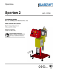
Now available in new white color
Modular Type FRL
Standard White Series
Modular Type FRL Standard White Series
MODULAR TYPE FRL STANDARD WHITE SERIES
CC-962A 2
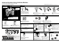
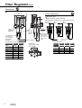
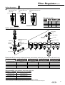
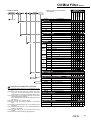
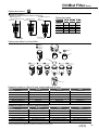
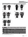
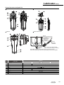
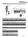
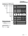
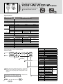
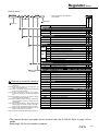
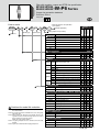
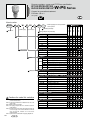
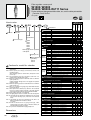
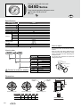
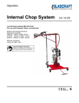
Enhanced Systems Using Full-Scale Modules
6\VWHPVDUHHDVLO\XSJUDGHGXVLQJXQL¿HGNH\GLPHQVLRQV
and a diverse range of options and variations.
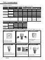
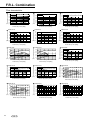
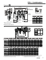
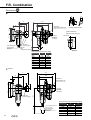
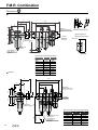
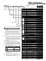
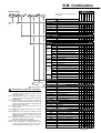
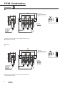
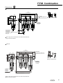
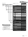
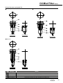
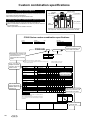
Combination
* Indicates series model no. 1, 2, 3, 4, 5, 6, 7, 8.
This page shows only the outline. Refer to contents later in this catalog for details.
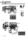
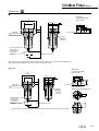
Mounting bracket
Page 152
"C*000-W"
FRL combination.
Lubricator
"L*000-W"
Supplies oil mist to
pneumatic lines.
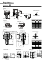
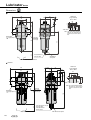
T type bracket (B110-W)
This bracket has two holes on the top and bottom to
¿[WKHGHYLFHWRJHWKHUZLWKWKHV\VWHPXSJUDGHWR
DZDOO7KLVEUDNHF\OLQGHUKDVRLOOHVVVSHFL¿FDWLRQV
The 3000-W Series and 4000-W Series are
coupled using B410-W. Use B410-W in that
case.
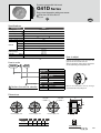
Pressure gauge
Page 199 to 209
Joiner "C*000-J*00-W"
8VHGDVD¿WWLQJIRUV\VWHPFRQ¿JXUDWLRQ
3000-W Series and 4000-W series can be
connected using J400-W.
C type bracket "B*20"
7KLVEUDFNHW¿[HVLVRODWHGSDUWVMXVWE\
¿WWLQJWKHPLQ
L type bracket "B*30"
7KLV EUDFNHW IL[HV SDUWV XVLQJ WKH SDQHO
mounting nut on the filter regulator or
regulator.
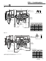
)RUDLU¿OWHU):)LOWHUUHJXODWRU::::
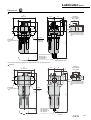
Regulator
$LU¿OWHU
Reverse type "R*000-W"
"F*000-W"
Depressurizes supply pressure
Effectively removes and supplies stable set pressure.
dust and moisture.
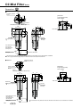
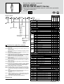
Element
)RUDLU¿OWHU):)LOWHUUHJXODWRU::::
Standard built in pressure gauge "G401-W"
Pressure gauge protrusions are eliminated while
maintaining performance equivalent to JIS Class 3.
Filter Regulator
Standard (5 m) element "blank"
This long-life element filters out dirt and
foreign particles, etc., from air.
Bowl, bowl guard and drain discharge
Optional submicron 0.3 m element "Y"
This dedicated element effectively separates
tar and carbon. (Non-reusable)
)RUDLU¿OWHU):RLOPLVW¿OWHU0:¿OWHUUHJXODWRU
W*000-W, W*100-W
* A bowl guard is installed on the plastic bowl as a standard.
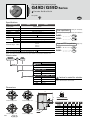
Distributor
Standard type "W*000-W" (Page 69)
Reverse type "W*100-W" (Page 77)
6SDFHHI¿FLHQW)5FRPELQDWLRQ
2LOPLVW¿OWHU
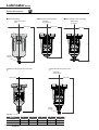
Pressure gauge with safety mark "G*0D"
The pressure's actual usage range is displayed with
red and green zones making visible control easier.
* Can be assembled using gauge plug.
Page 103
"M*000-W" "MX000-W"
Effectively removes oil and oil
mist from pneumatic lines.
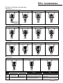
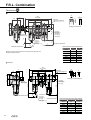
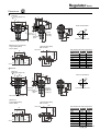
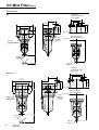
Pressure switch with digital display "PPD"
This unit functions as the pressure detector and display,
WKH212))VZLWFKDQGWKHVZLWFK
VH[WHUQDORXWSXW
* Integration is optional. Option "R1"
Page 153
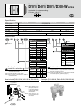
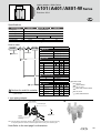
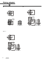
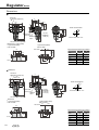
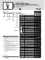
Piping adaptor
One way branch type "D*01W"
This distributor, which is
installed facing either upward
or downward, branches
pneumatic pressure piping.
The effective area of the
branch is large.
4 way branch type "D300-W"
The pipe branches in four
directions.
* For 3000-W/4000-W Series
Page 155
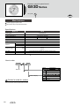
Straight type "A*00-W"
Using an adapter, isolated devices are
removed for maintenance instead of piping
being removed.
The adapter is convenient for changing the
connection bore size of the isolated device.
L type "A*01-W"
The device's in and out ports are turned by
90° and piped from top or bottom.
* Consult with CKD for vertical direction
piping.
Straight type
L type
Shut-off valve
Page 143 to 148
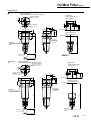
Bowl/bowl guard
For lubricator L*000-W
Pressure switch
Page 137 to 142
Pneumatic line pressure is repeatedly and accurately
checked.
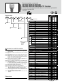
Ÿ3ODVWLFERZODQGERZOJXDUG
Ÿ0HWDOERZO
Bowl
Drainage
Polycarbonate
bowl
Intro 1
Manual drain cock
Nylon
bowl
Metal
bowl
Metal bowl with
manual drain cock
Blank (standard)
Z
M
M1
Automatic drain with manual override NO type
F
FZ
FM*
FM1
Automatic drain with manual override NC type
F1
F1Z
F1M*
F1M1
Refer to page 18 for details on
chemical resistance of the bowl.
Metal bowl not available for
1000 Series.
The asterisk (*) indicates the
manual cock with an Rc1/4
port.
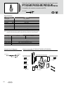
"P4000-W"
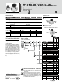
"V*000-W"
The pneumatic line is shut off and residual pressure is released.
Maintenance work This is also used to prevent accidents from
residual pressure during maintenance.
V3010-W with lock out also available
Plastic bowl and bowl guard
Material: "Blank" for polycarbonate, option
"Z" for standard nylon
* Option "C" for manual drain cock
* A bowl guard is installed on the plastic
bowl as a standard.
Check with CKD for other system upgrades.
Metal bowl
Use the metal bowl in an atmosphere
where plastic bowls cannot be used.
Material: Aluminum Option "M"
* Metal bowl not available for 1000
Series.
"PPD"
"PPX"
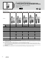
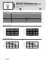
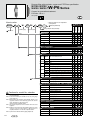
Intro 2
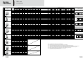
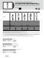
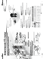
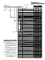
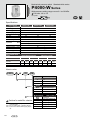
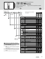
Series
variation
F.R.L. unit
(Combination)
F
Filter
F.R.L. combination
P.21
WL combination
R
Regulator Lubricator
Modular type FRL
P.35
FMR combination
P.41
WM combination
P.59
FFM combination
S
P
Combination of options (U***)
V
K
Pressure switch
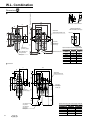
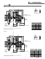
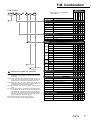
D101-W
P1100-W
P4100-W P4000-W V3000-W V3010-W
C2500-W F3000-W
R2000-W L3000-W
D401-W
P4100-W P4000-W V3000-W V3010-W
C3000-W F3000-W
R3000-W L3000-W
D401-W
P4100-W P4000-W V3000-W V3010-W
C4000-W F4000-W
R4000-W L4000-W
D401-W
P4100-W P4000-W V3000-W V3010-W
Note 5 C4000-20-W F4000-W
R4000-W L4000-W
D401-W
P4100-W P4000-W V3000-W V3010-W
C6500-W F6000-W
R6000-W L8000-W
D801-W
P8100-W
C8000-W F8000-W
R8000-W L8000-W
D801-W
P8100-W
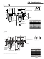
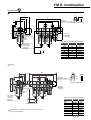
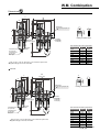
P1100-W
C2010-W
L3000-W
W2000-W
P4100-W P4000-W V3000-W V3010-W
C3010-W
L3000-W
W3000-W
P4100-W P4000-W V3000-W V3010-W
C4010-W
L4000-W
W4000-W
P4100-W P4000-W V3000-W V3010-W
L4000-W
W4000-W
P4100-W P4000-W V3000-W V3010-W
L8000-W
W8000-W
P8100-W
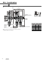
D101-W
P1100-W
C2020-W F2000-W
R2000-W
D401-W
P4100-W P4000-W V3000-W V3010-W
C2520-W F3000-W
R2000-W
D401-W
P4100-W P4000-W V3000-W V3010-W
C3020-W F3000-W
R3000-W
D401-W
P4100-W P4000-W V3000-W V3010-W
C4020-W F4000-W
R4000-W
D401-W
P4100-W P4000-W V3000-W V3010-W
Note 5 C4020-20-W F4000-W
R4000-W
D401-W
P4100-W P4000-W V3000-W V3010-W
C6020-W F6000-W
R6000-W
D801-W
P8100-W
C8020-W F8000-W
R8000-W
D801-W
P8100-W
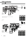
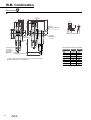
C1030-W F1000-W
R1000-W
M1000-W D101-W
P1100-W
C2030-W F2000-W
R2000-W
M2000-W D401-W
P4100-W P4000-W V3000-W V3010-W
C2530-W F3000-W
R2000-W
M3000-W D401-W
P4100-W P4000-W V3000-W V3010-W
C3030-W F3000-W
R3000-W
M3000-W D401-W
P4100-W P4000-W V3000-W V3010-W
C4030-W F4000-W
R4000-W
M4000-W D401-W
P4100-W P4000-W V3000-W V3010-W
Note 5 C4030-20-W F4000-W
R4000-W
M4000-W D401-W
P4100-W P4000-W V3000-W V3010-W
C6030-W F6000-W
R6000-W
M6000-W D801-W
P8100-W
C8030-W F8000-W
R8000-W
V6010-W
P8100-W
V6010-W
W2000-W M2000-W
P4100-W P4000-W V3000-W V3010-W
C3040-W
W3000-W M3000-W
P4100-W P4000-W V3000-W V3010-W
C4040-W
W4000-W M4000-W
P4100-W P4000-W V3000-W V3010-W
W4000-W M4000-W
P4100-W P4000-W V3000-W V3010-W
W8000-W M8000-W
P8100-W
M2000-W
M3000-W
C3050-W
R3000-W
M3000-W
C4050-W
R4000-W
M4000-W
R4000-W
M4000-W
C6050-W
R6000-W
M6000-W
C8050-W
R8000-W
M8000-W
C1060-W F1000-W
M1000-W
C2060-W F2000-W
M2000-W
C3060-W F3000-W
M3000-W
C4060-W F4000-W
M4000-W
Note 5 C4060-20-W F4000-W
M4000-W
C6060-W F6000-W
M6000-W
C8060-W F8000-W
C3070-W
C4070-W
C6070-W
C8070-W
): ȝ P
): ȝ P
): ȝ P
): ȝ P
): ȝ P
): ȝ P
): ȝ P
): ȝ P
): ȝ P
): ȝ P
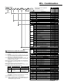
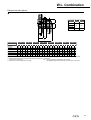
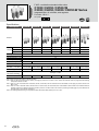
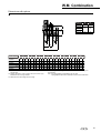
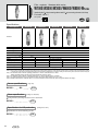
SV
SK
PV
PK
F
D
R
S or P
L
V or K
W
S or P
L
V or K
F
D
R
S or P V or K
Note 3
The piping adapter can be assembled on models marked with a
.
F
M
D
R
S or P V or K
Note 3
V6010-W
C2040-W
R2000-W
DSV DSK DPV DPK
V1000-W
P1100-W
R2000-W
DK
V6010-W
W1000-W M1000-W
C2550-W
DV
V1000-W
C1040-W
C2050-W
DP
V6010-W
R1000-W
M1000-W
DS
V1000-W
C1020-W F1000-W
R1000-W
K
V6010-W
W1000-W
C1050-W
V
V6010-W
L1000-W
C8040-W
P
V1000-W
C1010-W
M8000-W D801-W
S
Shut-off valve
D401-W
C8010-W
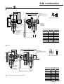
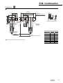
Combination position
D
2LOPLVW¿OWHU Distributor
R1000-W L1000-W
Note 5 C4070-20-W
P.65
D
R2000-W L3000-W
Note 5 C4050-20-W
P.53
FM combination
Filter/
Regulator
Available options
M
C1000-W F1000-W
Note 5 C4040-20-W
P.47
RM combination
W
C2000-W F2000-W
Note 5 C4010-20-W
P.29
FR combination
L
Piping
adaptor
Model no.
Piping
adaptor
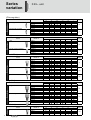
Available combinations
Series
The piping adapter can be assembled on models marked with a
.
V1000-W
W
S or P
M
V or K
V6010-W
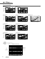
Note 1: Two T-brackets are included with the combination option.
Note 2: Mounting position of T type bracket will change depending on the combination.
Note 3: T-type bracket standard mounting position is on the inner side of the end product of each combination.
However, there will be an product mounted on the inner side of the piping adaptor when a piping adaptor is mounted on the end.
1RWH8VHWKHFXVWRPFRPELQDWLRQVSHFL¿FDWLRQVKHHWIRUXQDYDLODEOHFRPELQDWLRQVDQGFKDQJHVLQEUDFNHWPRXQWLQJSRVLWLRQ
Note 5: Piping adaptor set A400-20-W can be installed on both ends of C40*0-20-W (port size Rc3/4)
The port size is "15" (Rc1/2) for products other than the piping adapter,
Note 6: Only upward branching is available for option "D".
M8000-W
M3000-W
M4000-W
M4000-W
M6000-W
M8000-W
Read to "Safety Precautions" before use.
1
2
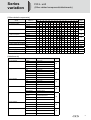
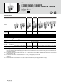
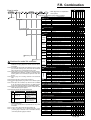
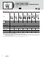
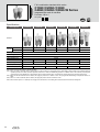
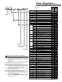
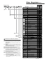
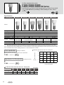
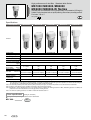
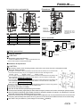
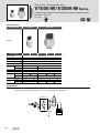
Series
variation
F.R.L. unit
(Filter regulator)
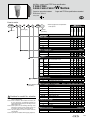
Series
Modular type
Filter regulator
5HYHUVH¿OWHU regulator
Model no.
Port size
1/8
1/4
3/8
1/2
3/4
1
W1000-W
W2000-W
W3000-W
W4000-W
W8000-W
W1100-W
W2100-W
W3100-W
W4100-W
W8100-W
Page
69
77
(Filter)
Series
Modular type
Filter
$LU¿OWHU medium pressure
Model no.
Port size
1/8
1/4
3/8
1/2
3/4
1
F1000-W
F2000-W
F3000-W
F4000-W
F6000-W
F8000-W
FM3000-W
FM4000-W
FM6000-W
FM8000-W
Page
85
159
2LOPLVW¿OWHU
Series
Modular type
2LOPLVW¿OWHU
+LJKSHUIRUPDQFHRLOPLVW¿OWHU
2LOPLVW¿OWHUIRUPHGLXPSUHVVXUH
Model no.
Port size
1/8
1/4
3/8
1/2
3/4
1
M1000-W
M2000-W
M3000-W
M4000-W
M6000-W
M8000-W
MX1000-W
MX3000-W
MX4000-W
MX6000-W
MX8000-W
MM3000-W
MM4000-W
MM6000-W
MM8000-W
Page
95
103
165
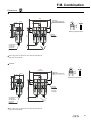
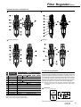
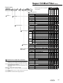
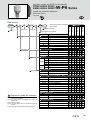
(Regulator)
Series
Modular type
Regulator
Reverse regulator
Regulator for medium pressure
Model no.
Port size
1/8
1/4
3/8
1/2
3/4
1
R1000-W
R2000-W
R3000-W
R4000-W
R6000-W
R8000-W
R1100-W
R2100-W
R3100-W
R4100-W
R6100-W
R8100-W
RM3000-W
RM4000-W
Page
113
121
171
(Lubricator)
Modular type
Series
3
Lubricator
Model no.
L1000-W
L3000-W
L4000-W
L8000-W
Port size
1/8
1/4
3/8
1/2
3/4
1
Page
129
Series
variation
F.R.L. unit
(Other related components/attachments)
(Other related components)
Series
Model no.
ø4
ø6
ø8
ø10 ø12
1/16
Port size
1/8 1/4 3/8
1/2
3/4
1
1 1/4
1 1/2
2
Page
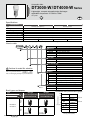
Automatic drain
DT3000/4000-W
213
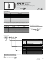
Air pressure switch
P4000-W
137
P*100-W
139
APS-W
210
Shut-off valve
V1000-W
143
V3000-W
Shut-off valve with key hole
(OSHA compliant)
V3010-W
Slow start valve
V3301-W
146
V6010-W
149
V3321-W
Thin pressure gauge
G401
199
Pressure gauge with safety sign G40D/50D
200
Pressure gauge with limit gauge G45D
201
G41D
202
General purpose pressure gauge G49D 59D
203
Pressure gauge for panel mount G53D
205
Pressure gauge with switch
207
G52D
(Attachments)
Series
T type bracket
C type bracket
L type bracket
Joiner
Distributor
Piping adaptor
L type piping adapter
Model no.
Applicable model
B110-W
1000 Series
B310-W
2000/3000 Series
B410-W
4000 Series
B810-W
6000/8000 Series
B120
1000 Series
B220
2000 Series
B320
3000 Series
B420
4000 Series
B620
6000 Series
B820
8000 Series
B130
1000 Series
B230
2000 Series
B330
3000 Series
B430
4000/6000 Series
C1000-J100-W
1000 Series
C1000-J100-W
2000/3000/4000 Series
C8000-J800-W
6000/8000 Series
D101-W
1000 Series
D401-W
2000/3000/4000 Series
D801-W
6000/8000 Series
D300-W
2000/3000/4000 Series
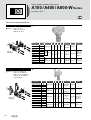
A100-W
1000 Series
A400-W
2000/3000/4000 Series
A800-W
6000/8000 Series
A101-W
1000 Series
A401-W
2000/3000/4000 Series
A801-W
6000/8000 Series
Page
152
152
152
152
153
155
156
4
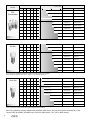
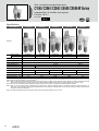
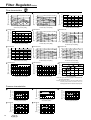
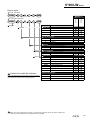
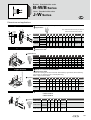
Port size
Series
Maximum flow rate
m 3/min. (ANR)
1/8
1/4
3/8
1/2
3/4
1
●
●
●
●
●
●
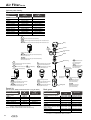
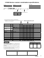
FRL
Combination
0.1
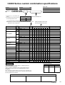
Automatic drain
C1000-6-W
-
C1000-8-W
-
C2000-8-W
C2000-8-W-F1
1.7
C2000-10-W
C2000-10-W-F1
1.28
C3000-8-W
C3000-8-W-F
C3000-10-W
C3000-10-W-F
C4000-10-W
C4000-10-W-F
C4000-15-W
C4000-15-W-F
C8000-20-W
C8000-20-W-F
C8000-25-W
C8000-25-W-F
10
0.45
0.63
●
●
Manual drain
1.0
●
1.2
●
Model no.
1.75
2.4
3.0
7.0
7.5
*Flow rate when supplied pressure is 0.7MPa, set pressure 0.5MPa, pressure drop 0.1MPa.
●
Air filter
●
●
●
●
●
●
-
F1000-8-W
-
F2000-8-W
F2000-8-W-F1, Note 1
1.7
F2000-10-W
F2000-10-W-F1, Note 1
1.23
F3000-8-W
F3000-8-W-F
1.5
F3000-10-W
F3000-10-W-F
2.14
F4000-10-W
F4000-10-W-F
3.0
F4000-15-W
F4000-15-W-F
6.4
F8000-20-W
F8000-20-W-F
6.8
F8000-25-W
F8000-25-W-F
0.61
●
●
F1000-6-W
0.46
1.3
●
*Flow rate when supplied pressure is 0.7MPa and pressure drop is 0.02MPa.
Note 1: Refer to the max. flow rate on page 13. for automatic drain “F1”
●
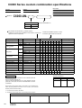
Oil mist filter
●
●
●
●
●
●
●
0.15 (0.01μm)
M1000-6-W
-
0.15 (0.01μm)
M1000-8-W
-
●
0.25 (0.01μm)
M2000-8-W
M2000-8-W-F1
●
0.25 (0.01μm)
M2000-10-W
M2000-10-W-F1
0.36 (0.01μm)
M3000-8-W
M3000-8-W-F1
0.36 (0.01μm)
M3000-10-W
M3000-10-W-F1
0.825 (0.01μm)
M4000-10-W
M4000-10-W-F1
0.825 (0.01μm)
M4000-15-W
M4000-15-W-F1
2.6 (0.01μm)
M8000-20-W
M8000-20-W-F1
2.6 (0.01μm)
M8000-25-W
M8000-25-W-F1
*This is the flow at supply pressure 0.7MPa pressure drop 0.01MPa.
Note: By combining a piping adapter with the 4000, 8000 Series, the port size can be increased by 1 size.
Contact CKD for details. (available up to Rc3/4 for 4000 series , Rc1 1/4 for 8000 series)
5
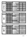
Port size
Series
Maximum flow rate
Model no.
m 3/min. (ANR)
1/8
1/4
3/8
1/2
3/4
1
●
●
●
●
●
●
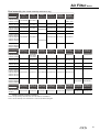
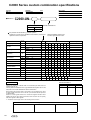
Filter
Regulator
0.1
1.0
Manual drain
Automatic drain
W1000-6-W
-
1.15
W1000-8-W
-
●
1.5
W2000-8-W
W2000-8-W-F1, Note 1
●
2.0
W2000-10-W
W2000-10-W-F1, Note 1
W3000-8-W
W3000-8-W-F
W3000-10-W
W3000-10-W-F
4.35
W4000-10-W
W4000-10-W-F
4.75
W4000-15-W
W4000-15-W-F
10.0
W8000-20-W
W8000-20-W-F
10.0
W8000-25-W
W8000-25-W-F
0.83
●
●
10
2.15
2.43
*Flow rate when supplied pressure is 0.7MPa, set pressure 0.5MPa, and pressure drop is 0.1MPa.
Note 1: Refer to the max. flow rate on Page 13. for automatic drain “F1”
Port size
Series
1/8
1/4
3/8
1/2
●
●
●
●
●
●
Maximum flow rate
3
m /min. (ANR)
3/4
1
0.1
1.0
10
0.77
Model no.
With standard pressure gauge
R1000-6-W
Regulator
●
●
1.35
R1000-8-W
1.75
R2000-8-W
●
2.5
R2000-10-W
2.6
R3000-10-W
4.4
R4000-10-W
5.0
R4000-15-W
14.0
11.0
R8000-20-W
R8000-25-W
*Flow rate when supplied pressure is 0.7MPa, set pressure 0.5MPa, and pressure drop is 0.1MPa.
Port size
Series
Maximum flow rate
m 3/min. (ANR)
1/8
1/4
3/8
1/2
3/4
1
●
●
●
●
●
●
●
●
0.1
1.0
10
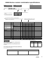
0.55
Model no.
Standard
L1000-6-W
Lubricator
0.7
L1000-8-W
1.1
L3000-8-W
2.25
L3000-10-W
L4000-10-W
1.7
2.7
L4000-15-W
6.3
10.0
L8000-20-W
L8000-25-W
*Flow rate when supplied pressure is 0.5MPa and Pressure drop is 0.03MPa.
6
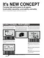
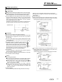
It's NEW CONCEPT
Pursuing high performance in all aspects,
functionality, operability, serviceability, and safety.
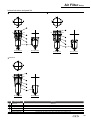
>)LOWHUIRUFRPSUHVVHGDLUUHJXODWRU¿OWHURWKHUFRPSRQHQWV@
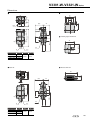
FUNCTIONAL FEATURES
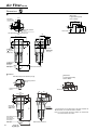
Compact module
Long service life element
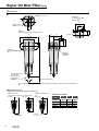
F.R.L. main dimensions (width and depth) are
integrated into a compact module. Accurate assembly
dimensions are obtained with simple calculation.
COMPACT MODULE
A
This element incorporates CKD's original chemical
¿EHUVWUXFWXUHSDWHQWSHQGLQJZKLFKKDVDURXJK
surface and gradually becomes finer toward the
inside. Clogging is greatly reduced and element
OLIHJUHDWO\H[WHQGHG7KHUHLVQRUULVNRIUXVWLQJ
LONG LIFE ELEMENT
R
FLAT FACE
Separate type
L
B
F
Embedded pressure gauge for space saving
The conventional protruding pressure gauge
wasted space on the front, and posed risks to
users. Neat design and safety are realized by
embedding the pressure gauge into the body.
B
Module
type
A
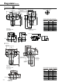
Unit: mm
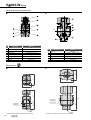
C1000-W C2000-W C2500-W C3000-W C4000-W C6500-W C8000-W
A
B
40 50 50 63 63 50 63 63
80 90 90 100 100
Unit: mm
40×3 50×2+63 63×2+50 63×3 80×3 90×2+100 100×3
C1000-W C2000-W C2500-W C3000-W C4000-W C6500-W C8000-W
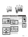
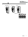
Lighter by 50% from conventional models.
Module type A 57
Hybrid material (aluminum die cast with resin
cover) provides strength and cuts weight
50% over the conventional type. (C4000
comparison)
Conventional product B 74
LIGHT WEIGHT
62 70.5 63
-
79 100 100
109 109 124 131 131
Mechanism to prevent oil dripping
during primary side pressure drop
Reduces dripping of oil discharge of shut-off
valve.
Corrosion resistant, safe bowl guard
Appropriate for piping in limited space or
complicated piping.
Separate type
Module type
Unit: kg
C1000-W C2000-W C2500-W C3000-W C4000-W C6500-W C8000-W
Module type 0.4 1.01 1.01 1.15 1.79 3.64 4.5
Conventional products 0.7
-
1.8 1.8 3.4 7.2 7.2
Read Precautions on page 11 to 18 before use.
7
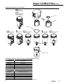
Gauge plug
The gauge plug is sealed even without a pipe
plug. (Refer to page 209 when using screw-in
type pressure gauge)
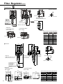
OPERATIVE FEATURES
2LOGULSDGMXVWPHQWNQREZLWKORFN
Tool free pressure control
1RWRROVUHTXLUHGWRDGMXVWSUHVVXUH7KHNQRELVORFNHG
with a single push, The knob is locked with a single
push, and is easily operated when setting pressure.
TOOL-FREE SETTING
F.R.L.
R1000-W
R2000-W
R3000-W
R4000-W
R6000-W
R8000-W
(DV\ WRRO IUHH RLO GRVLQJ DGMXVWPHQW $
stopper is provided in the opening direction
to function as a lock, and increase safety.
The number on the dial are used as a guide
DIWHUDGMXVWLQJGULSSLQJ
.HHSWKHRLOGRVLQJDGMXVWPHQWEHORZ1 m
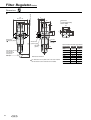
O ring fall out prevention
An O ring slot is provided
on the bowl to prevent O
ring from falling out during bowl attachment and
removal for a safe and
accurate seal
O-RING SETTING
Body
TOOL-FREE SETTING
$GMXVWLQJGRPH
Bowl
Oil dosing
DGMXVWPHQW
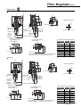
(DV\WRXVH¿OWHUHOHPHQW
PULL
Easy to accommodate with panel mount
Double plastic structure
When the panel mounting nut is loosened,
WKHQXWDFWVDVDMDFNDQGHQDEOHVWKHNQRE A double plastic structure is used so oil
WREHUHPRYHGHDVLO\)L[WKHQXWWRPRXQWLQ GULSSLQJLVFRQ¿UPHGIURP
the panel. The L-type bracket is also installed
similarly to the nut.
360°
7KH ERG\ FDQ EH IL[HG VHFXUHO\ ZLWKRXW SOD\
ZLWKWKH/W\SHEUDFNHW([FOXGLQJ6HULHV
The integrated element
is removed by turning
the baffle 45° to the
left.
(1000-W Series only)
EASY PANEL MOUNT
Nut
Knob R1000-W
R2000-W
R3000-W
R4000-W
R6000-W
F.R.L.
L1000-W
L3000-W
L4000-W
L8000-W
(DV\UHPRYDOLQWHJUDWHG¿OWHUHOHPHQW
Note: Install the nut before installing the knob. (With
the R2000-W, the nut is removed without
removing the knob.)
The integrated bowl and bowl guard are
easily attached and removed by operating
the latch. (No latch for 1000-W series)
Mount and remove the bowl and bowl guard
after checking that pressure is not being
applied.
8
F.R.L Combination
Description of options
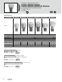
&RPELQDWLRQOLVWVRIGUDLQDJHDQGERZOPDWHULDORI¿OWHU D on how to order)
Applicable series
1000-W Series
2-W Series
3000-W Series
4000-W Series
6000-W Series
8000-W Series
Bowl material
Plastic bowl
Manual drain cock
Automatic drain with manual cock Large automatic drain with manual cock
NO type
NC type
NO type
NC type
Polycarbonate
(Blank)
×
(Symbol: F1) ×
×
Nylon
(Symbol: Z)
×
(Symbol: F1Z) ×
×
Metal bowl
Aluminum
Plastic bowl
Polycarbonate
×
×
(Blank)
×
×
(Symbol: F)
×
(Symbol: F1) ×
×
×
Nylon
(Symbol: Z)
(Symbol: FZ)
(Symbol: F1Z) ×
Metal bowl
Aluminum
(Symbol: M/M1)
(Symbol: F1/FM1)
(Symbol: F1M/F1M1) ×
Plastic bowl
Polycarbonate
(Blank)
(Symbol: F)
(Symbol: F1)
(Symbol: FF)
(Symbol: FF1)
Nylon
(Symbol: Z)
(Symbol: FZ)
(Symbol: F1Z)
(Symbol: FFZ)
(Symbol: FF1Z)
Aluminum
(Symbol: M/M1)
(Symbol: F1/FM1)
(Symbol: F1M/F1M1)
(Symbol: F1)
(Symbol FF1M/FF1M1)
Metal bowl
×
In a nonpressurized state, Air is not purged Drainage is automatically Air is not purged during
Features
-
such as at night, the valve d u r i n g i n i t i a l discharged when discharge initial pressurization when
opens and drainage is pressurization.
performance is high and discharge performance is
discharged automatically.
the unit is not pressurized. high.
Combination lists of drainage and bowl material of lubricator ( D on how to order)
Applicable series
1000-W Series
2000-W Series
2500-W Series
3000-W Series
4000-W Series
6000-W Series
8000-W Series
Bowl material
Plastic bowl
No manual cock With manual cock
Polycarbonate
(Blank)
Nylon
(Symbol: Z)
(Symbol: CZ)
Metal bowl
Aluminum
Plastic bowl
Polycarbonate
(Blank)
Nylon
(Symbol: Z)
(Symbol: CZ)
Aluminum
(Symbol: M)
(Symbol: CM/CM1)
Metal bowl
×
(Symbol: C)
×
(Symbol: C)
'HVFULSWLRQRISUHVVXUHUDQJHSUHVVXUHJDXJHDQGÀRZGLUHFWLRQRSWLRQV\PERO D on how to order)
Option symbol: L
Pressure display: 0 to 0.4 MPa
Pressure range: 0 to 0.35 MPa
Pressure gauge: G401-W-P04
Option symbol: T8/T6
Option symbol: N
Pressure gauge not included
because round pressure gauge is attached.
Pressure gauge mounting port is open.
Refer to page 209 when mounting a pressure
gauge.
Option symbol: R1/R2 (note)
R2
Pressure switch with display PPD assembled
Digital pressure sensor PPX included.
5HIHU WR 3QHXPDWLF 9DFXXP DQG$X[LOLDU\
Components (Catalog No. CB-024SA)" for
details)
(Note) Option symbol "R1" is not available for C*000-W, C*010-W Series.
9
Without pressure gauge
The Rc1/4 gauge port is sealed when the
plug is assembled.
Refer to page 209 when mounting a pressure
gauge.
Air will not relief.
R1
Option symbol: T
Option symbol: X1
OUT
IN
The right side will be IN with the pressure
gauge facing forward.
F.R.L Combination
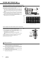
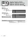
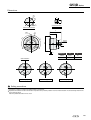
3ULQFLSOHVRIÀRDWW\SHDXWRPDWLFGUDLQ
3ULQFLSOHVRIÀRDWW\SHDXWRPDWLFGUDLQ
NO type (F, FF)
3000-W/4000-W/6000-W/8000-W Series
Non-pressurized state
Pressurized state
Float rising, discharging (pressurized)
Float lowering, discharge complete (pressurized)
(Closed)
(Opened)
(Closed)
Non-pressurized state
Pressurized state
Float rising, discharging (pressurized)
Float lowering, discharge complete (pressurized)
(Closed)
(Closed)
(Opened)
(Closed)
Float rising, discharging (pressurized)
Float lowering, discharge complete (pressurized)
(Opened)
(Closed)
(Opened)
Purge occurance
below 0.1MPa
NC type (F1, FF1)
3000-W/4000-W/6000-W/8000-W Series
NC type (F1)
1000-W Series
Non-pressurized state
Pressurized state
(Closed)
(Closed)
NC type (F1)
2000-W Series
Non-pressurized state Pressurized state
Float rising, discharging (pressurized)
Float lowering, discharge complete (pressurized)
(Closed)
(Opened)
(Closed)
Operation principles
Non-pressurized (such as night time)
Pressurized
NO
Type
Drainage discharge is Drainage is discharged with air from the drainage
opened and drainage is discharge section temporarily until pressure
discharged naturally.
becomes the minimum activation pressure or higher.
$IWHU¿OOLQJWKHGUDLQDJHGLVFKDUJHVHFWLRQLVFORVHG
NC
Type
Drainage discharge section will be closed.
Features
Notes
Drainage is discharged naturally in the nonpressurized
state (nighttime, etc.), so user discharge is not required.
In the pressurized state, once pressure is attained, drainage is
automatically discharged when it accumulates at a set level.
This type is suitable for a compressor (0.75 kW or less) having a small discharge.
There is no temporary air purging during pressurization.
It will automatically discharge if drain accumulates to a certain level after pressurizing.
As indicated in features, air and drainage are temporarily discharged until
the pressure attains the minimum activation so pressure may not be
VXI¿FLHQWZLWKDFRPSUHVVRUN:RUOHVVKDYLQJDVPDOOGLVFKDUJHÀRZ
Use a NC type in this case.
Drainage is not discharged in a nonpressurized state (nighttime, etc.),
so user discharge is required in applications where large amounts of
drainage are generated in a nonpressurized state (nighttime, etc.).
10
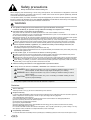
Safety precautions
Always read this section before starting use.
When designing and manufacturing a device using CKD products, the manufacturer is obligated to check that
device safety mechanism, pneumatic control circuit, or water control circuit and the system operated by electrical
control that controls the devices is secured.
It is important to select, use, handle, and maintain the product appropriately to ensure that the CKD product is used safely.
Be sure to observe the description given under DANGER, WARNING and CAUTION to assure safety of the equipment.
Check that device safety is ensured, and manufacture a safe device.
WARNING
This product is designed and manufactured as a general industrial machine part.
,WPXVWEHKDQGOHGE\DQRSHUDWRUKDYLQJVXI¿FLHQWNQRZOHGJHDQGH[SHULHQFHLQKDQGOLQJ
8VHWKLVSURGXFWLQDFFRUGDQFHRIVSHFL¿FDWLRQV
7KLVSURGXFWPXVWEHXVHGZLWKLQLWVVWDWHGVSHFL¿FDWLRQV,WPXVWQRWEHPRGL¿HGRUPDFKLQHG
This product is intended for use as a general-purpose industrial device or part. It is not intended for use outdoors or
for use under the following conditions or environment.
(Note that this product can be used when CKD is consulted prior to use and the customer consents to CKD product
VSHFL¿FDWLRQV7KHFXVWRPHUPXVWSURYLGHVDIHW\PHDVXUHVWRDYRLGULVNVLQWKHHYHQWRISUREOHPV
1 Use for special applications requiring safety including nuclear energy, railroad, aviation, ship, vehicle, medical equipment, equipment or applications
coming into contact with beverage or food, amusement equipment, emergency shutoff circuits, press machine, brake circuits, or for safeguard.
2 Use for applications where life or assets could be adversely affected, and special safety measures are required.
Observe corporate standards, regulations, etc., related to the safety of device design and control, etc.
ISO 4414, JIS B 8370 (pneumatic system rules)
JFPS2008 (Principles for pneumatic cylinder selection and use)
Including High Pressure Gas Maintenance Law, Occupational Safety and Sanitation Laws, other safety rules, body
standards and regulations, etc.
Do not handle, pipe, or remove devices before confirming safety.
,QVSHFWDQGVHUYLFHWKHPDFKLQHDQGGHYLFHVDIWHUFRQ¿UPLQJVDIHW\RIWKHHQWLUHV\VWHPUHODWHGWRWKLVSURGXFW
Note that there may be hot or charged sections even after operation is stopped.
3 When inspecting or servicing the device, turn off the energy source (air supply or water supply), and turn off power to the facility.
Discharge any compressed air from the system, and pay enough attention to possible water leakage and leakage of electricity.
4 When starting or restarting a machine or device that incorporates pneumatic components, make sure that the
system safety, such as pop-out prevention measures are secured.
1
2
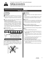
Observe warnings ad cautions on the pages below to prevent accidents.
The safety cautions are ranked as "DANGER", "WARNING" and "CAUTION" in this section.
DANGER:
When a dangerous situation may occur if handling is mistaken leading to fatal or
VHULRXVLQMXULHVRUZKHQWKHUHLVDKLJKGHJUHHRIHPHUJHQF\WRDZDUQLQJ
WARNING:
When a dangerous situation may occur if handling is mistaken leading to fatal or
VHULRXVLQMXULHV
When a dangerous situation may occur if handling is mistaken leading to minor
LQMXULHVRUSK\VLFDOGDPDJH
CAUTION:
Even items described under CAUTION may cause serious results.
,QDQ\FDVHLPSRUWDQWLQIRUPDWLRQWKDWPXVWEHREVHUYHGLVH[SODLQHG
Disclaimer
Term of warranty
:DUUDQW\3HULRGLVRQH\HDUIURPWKH¿UVWGHOLYHU\WRWKHFXVWRPHU
Scope of warranty
In case any defect attributable to CKD is found during the Warranty Period, CKD shall, at its own discretion, repair the
GHIHFWRUUHSODFHWKHUHOHYDQWSURGXFWLQZKROHRULQSDUWDFFRUGLQJWRLWVRZQMXGJHPHQW
This Limited Warranty will not apply to:
3URGXFWDEXVHPLVXVHFRQWUDU\WRFRQGLWLRQVHQYLURQPHQWUHFRPPHQGHGLQLWVFDWDORJVVSHFL¿FDWLRQV
(2) Failure caused by other than the delivered product
(3) Use other than original design purposes.
7KLUGSDUW\UHSDLUPRGL¿FDWLRQ
(5) Failure caused by reason that is unforeseeable with technology put into practical use at the time of delivery
)DLOXUHDWWULEXWDEOHWRIRUFHPDMHXUH
,QQRHYHQWVKDOO&.'EHOLDEOHIRUEXVLQHVVLQWHUUXSWLRQVORVVRISUR¿WVSHUVRQDOLQMXU\FRVWVRIGHOD\RUIRUDQ\
other special, indirect, incidental or consequential losses, costs or damages.
&RPSDWLELOLW\FRQ¿UPDWLRQ
,QQRHYHQWVKDOO&.'EHOLDEOHIRUPHUFKDQWDELOLW\RU¿WQHVVIRUDSDUWLFXODUSXUSRVHQRWZLWKVWDQGLQJDQ\GLVFORVXUHWR&.'RIWKHXVHWRZKLFKWKHSURGXFWLVWREHSXW
11
Pneumatic components (F.R.L. unit (modular design))
Safety precautions
Always read this section before starting use.
5HIHUWR³3QHXPDWLF9DFXXPDQG$X[LOLDU\&RPSRQHQWV&DWDORJ1R&%6$´SUHFDXWLRQVIRUSQHXPDWLFFRPSRQHQWVLQJHQHUDO
6SHFL¿FSUHFDXWLRQV)5/PRGXODUGHVLJQ
Design & Selection
WARNING
1. Common
WARNING
This product is for industrial use only. It must not be
used in components or circuits for medical
equipment or components that involve human lives.
Large drainage
Install the air dryer and drain separator before the
DLU¿OWHU
Hot and humid air or large drainage from the comp
could shorten the device life or result in corrosion.
Air filter, lubricator plastic bowl, lubricator's drip
window, and pressure gauge lens
Material is polycarbonate. It cannot be used in
environments containing synthetic oil, organic
solvents, chemicals, coolant, screw locking agent,
leak detection solutions, or hot water, etc., or where
these substances may come in contact with them.
Refer to page 18 for details on bowl chemical resistance.
Ultra dry air
Rubber parts for the regulator could deteriorate
TXLFNO\VRXVHRIDÀXRULQHUXEEHUYDOYHDVVHPEO\
is recommended. Consult with CKD if necessary.
Piping load torque
Check that the piping load or torque is not applied
to the body or piping sections.
Use the automatic drain under the working conditions
below.
Otherwise, malfunctioning may occur.
Series
0D[WRUTXH
N m
1000-W 2000-W 3000-W 4000-W 6000-W 8000-W
15
15
50
50
100
100
With the 1000-W Series, application
of a torque of 30 N·m or more on
piping could damage piping. Use
within the specified torque, even
when using the piping adapter.
$YRLGSLSLQJVLPLODUWRWKHIROORZLQJH[DPSOH
Water lubricated compressor circuits
Ta k e m e a s u r e s t o p r e v e n t c h l o r i n e - b a s e d
substances from entering the compressed air.
12W\SHDXWRPDWLFGUDLQH[KDXVWZLWKRXWSUHVVXUL]HG)))
Use a compressor with a capacity of 0.75 kW {90l/min
>$15@`RUPRUH
Set the working pressure to 0.1 MPa or more. (Initially
generated drainage and air are purged until pressure reaches
0.1 MPa.)
1&W\SHDXWRPDWLFGUDLQH[KDXVWZLWKRXWSUHVVXUL]HG)))
Can be used with compressor with 0.75kw or less.
Set the working pressure to 0.15 MPa or more.
1000-W, 2000-W Series NC automatic drain
$YRLG SLSLQJ ¿[HG ZLWK D VLQJOH VXSSRUW DV WKLV FDQ
UHVXOWLQH[FHVVLYHIRUFHDQGOHDGWRGDPDJH
With the 1000-W Series, application of a torque of 30
N·m or more on piping could damage piping. Use
within the specified torque, even when using the
piping adapter.
6HWWKHZRUNLQJÀRZWROHVVWKDQWKHPD[LPXPZRUNLQJÀRZ
In places with high vibration, such as where the compressor is
installed, air could leak from the drain port when the float
vibrates. Avoid this use.
'RQRWOHWWKHGUDLQRYHUÀRZDVLWPD\OHDGWRPDOIXQFWLRQLQJ
12
F.R.L. unit (modular design)
5HJXODWRU¿OWHUZLWKUHJXODWRU
WARNING
Install a safety device where an output pressure
H[FHHGLQJ WKH UHJXODWRU
V VHW SUHVVXUH YDOXH FRXOG
result in damage or faulty operation of secondary
side devices.
The regulator cannot process residual pressure
(remove secondary pressure) when primary
pressure is released.
Use a regulator with a check valve when residual
pressure must be processed.
5. Shut-off valve
WARNING
Precautions for shut-off valve
The EXH port is dedicated for installation of the silencer.
Tighten with a torque of 3 N·m or less -- as far as is
tightened manually.
Avoid piping that applies piping load or torque, etc., to the
EXH port.
,I H[KDXVW LV LQFRPSOHWH EHFDXVH RI DLU TXDOLW\ PDQXDOO\
discharge air by operating the knob (turn and raise).
6. Pressure gauge
CAUTION
In some cases, the regulator cannot be used for
secondary side sealing circuits or balance circuits.
CAUTION
KHQ XVLQJ WKLV XQLW IRU D ODUJH ÀRZ HWF LQVWDOO D
:
pressure gauge as shown below so that secondary
pressure is measured accurately.
Set the regulator's secondary pressure to 85% or
less that of the primary side. The pressure could
drop further.
When using regulators in parallel as shown below,
do not use the OUT side as a closed circuit. If a
closed circuit is required, set a check valve at the
regulator's OUT side.
D300-W or tees pipe.
IN
OUT
Pressure gauge
R.W.
Regarding G45D
The chemical resistance of the lens is shown below.
Avoid using products in an atmosphere where chemicals
are contained in compressed air, the atmosphere, or
where they could adhere to parts.
Use in this state could lead to bowl damage and accidents.
Chemical resistance of lens
Types of chemicals Categories of chemicals Main products containing the chemical ([DPSOHRIJHQHUDOXVDJH Lens
3. Lubricator
WARNING
Lubricator
Consult with CKD for using lubrication with an air
motor or bearings. Also consult with CKD when
using this unit at a high frequency such as in a
press machine.
CAUTION
If the working air rate is low for the lubricator, oil
may not drip.
Check the minimum air rate required for dripping oil.
4. Pressure switch
CAUTION
When using the compact pressure switch PPD or
digital pressure sensor PPX, avoid using as a set
with the lubricator. The switch is not a drip-proof
structure, so operation could be disabled if the
lubricating oil comes in contact with it.
13
Acid washings from
Hydrochloric acid, sulfuric
metals, acidic
DFLGK\GURÀXRULFDFLG
Acid
degreasing solutions,
Phosphoric acid, chrome
skin treatment
acid, etc.
solutions
Contained in
Benzene, toluene
Aromatic
paint thinner
Xylene, ethyl benzene,
hydrocarbon
(benzene,
styrene
WROXHQH[\OHQH
Anti-freeze,
0HWKDQROHWKDQROF\FORKH[DQRO
Alcohol
eakage detection
benzyl alcohol
agent
Carbolic acid, cresol
Antiseptic
Phenol
Nafthol, etc.
solution.
Acetone, methyl ethyl
Ketone N H W R Q H F \ F O R K H [ D Q R Q H acetophenone, etc.
Organic
'\HVR[DOLFDFLG
chemicals
for aluminum
Formic acid, acetic acid, p r o c e s s i n g ;
&DUER[\OLF butyl acid
phthalic acid for
acid
DFU\OLFDFLGR[DOLFDFLG
paint base and
Phtalic acid, etc.
leak-detection
agents e (dowel
pin) from rear
Glycocholic acid, lactic acid,
2[RDFLG
malic acid, citric acid, tartarate
Methylamine, diethylamine,
Amine e t h y l a m i n e , a n i l i n e , Brake oil additive
acetoacetanilide, etc.
Inorganic
chemicals
: Do not use (Lens will be damaged)
F.R.L. unit (modular design)
6SHFL¿FSUHFDXWLRQV
Installation & Adjustment
Drain piping
1. Common
CAUTION
YRLG LQVWDOOLQJ WKLV SURGXFW ZKHUH LW LV VXEMHFW WR
$
direct UV rays.
Flush and wash pipes to be used.
Dirt or foreign materials in piping will lower product
performance.
Check that foreign materials do not enter when
WLJKWHQLQJSLSHVRUMRLQWV
:KHQ VFUHZLQJ LQ SLSLQJ RU MRLQWV FKHFN WKDW VZDUI IURP
piping threads or sealing agent does not get inside. Dirt or
foreign materials in piping will lower product performance.
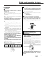
How to use the F.R.L. correctly
1. Set the regulator pressure setting to increase.
After setting pressure, lock the handle. Check
primary pressure carefully before setting
pressure.
2. Check the arrow indicating the air inlet before
connection. Reverse connection causes
malfunctions.
3. Install the air filter and lubricator vertically with
the case facing downward. Failure to do so could
lead to disconnection or malfunction.
4. Use of the automatic drain where vibration is
present could cause faults and malfunctions.
Pipe the automatic drain in the following conditions.
Otherwise, malfunctioning may occur.
Use an inner diameter of 5.7 or more and piping of
5 m or less for the drainage section.
Do not pipe in a manner which will apply lateral load
to the bowl.
)L[ WKH KH[DJRQ VLGH RI WKH FRFN EHIRUH VFUHZLQJ
WKHMRLQWHWFLQWRWKH5FIHPDOHVFUHZ
Piping screw-in torque
0DNH VXUH WKDW H[FHVVLYH WRUTXH LV QRW DSSOLHG RQ
the body and piping when piping.
&RQ¿UPWKDWWKHGUDLQFRFNLVFORVHGEHIRUHLQVHUWLQJWKH
tube. The drain piping for the plastic bowl has a barbed
QLSSOHDQGFDQEHGLUHFWO\LQVWDOOHG+RZHYHUFRQ¿UPWKDW
the drain cock is closed before inserting the tube.
Drain cock tightening torque
7KHPD[WLJKWHQLQJWRUTXHRIWKHGUDLQFRFNIRUWKHSODVWLF
bowl is as follows.
1000 Series: 0.1N m
Others: 0.5N m
Drain piping of metal bowl with automatic drain
)L[ WKH FRFN
V KH[DJRQDO IDFH EHIRUH VFUHZLQJ WKH
MRLQWHWFLQWRWKHGUDLQSRUW
VIHPDOHWKUHDGV:KHQ
using the metal bowl with automatic drain, if the
GUDLQ LV SLSHG ZLWK D WLJKWHQLQJ MRLQW PDQXDO
operation is not possible.
Cock
KH[DJRQDO
O
S
Drain port
Metal bowl
(automatic drain)
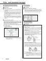
Drain with pressure detection port
For F6000- -W-Q/M6000- -W-Q/MX6000-W-Q/F8000- -W-Q/M8000- -W-Q/
MX 8000- -W-Q
Pressure detection port is available as an option for
F6000-W M6000-W MX6000-W F8000-W
M8000-W MX8000-W.
7KHOLIHRIWKH¿OWHUHOHPHQWRURLOPLVW¿OWHUPDQWOH
assembly is visually checked by assembling the
differential pressure gauge GA400-8-P02 into the
pressure detection port.
When selecting option Q and X1 simultaneously for
F6000-W and M6000-W and mounting differential
pressure gauge GA400, raise the gauge with piping
material so that it does not interfere.
Differentual pressure gauge GA400-8-P02
Series
0D[WRUTXH
N m
1000-W 2000-W 3000-W 4000-W 6000-W 8000-W
15
30
30
30
70
70
Pressure detection port
Check high and low-pressure port positions for the
differential pressure installation port, and install
correctly.
14
F.R.L. unit (modular design)
5HJXODWRU¿OWHUZLWKUHJXODWRU
CAUTION
CAUTION
5HJXODWRU¿OWHUUHJXODWRU
$GMXVWPHQWRIOXEULFDWRURLOGULSSDJH
Lightly tighten (0.6 N·m or less) mounting screws for
embedded pressure gauge G401-W-OP, G401-W, and
gauge plug.
When installing the pressure gauge with a safety mark on
the gauge plug, or when installing a general screw-in
pressure gauge, tighten with a torque of 15N·m or less.
'RQRWPRYHRUVZLQJWKHSURGXFWKROGLQJWKHDGMXVWPHQW
knob on the regulator.
'RQRWDSSO\SUHVVXUHH[FHHGLQJWKHSUHVVXUHJDXJH
VIXOO
scale, This will cause the pressure gauge to break. (Pay
H[WUD FDXWLRQ ZKHQ XVLQJ DQG 03D SUHVVXUH
gauges)
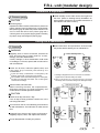
Panel mounting the regulator
When the panel mounting nut is loosened, the nut
DFWVDVDMDFNDQGHQDEOHVWKHNQREWREHUHPRYHG
HDVLO\)L[WKHQXWWRPRXQWLQWKHSDQHO7KH/W\SH
bracket is also installed similarly to the nut.
7KH ERG\ FDQ EH ¿[HG VHFXUHO\ ZLWKRXW SOD\ ZLWK
the L-type bracket)
([FOXGLQJ6HULHV
EASY
PANEL MOUNT
Nut
3. Lubricator
Knob
R1000-W
R2000-W
R3000-W
R4000-W
R6000-W
Note: Install the nut before installing the knob.
(With the R2000-W, the nut is removed without
removing the knob.)
$GMXVWWKHRLOUDWHE\WXUQLQJWKHDGMXVWLQJGRPHZLWKEDUH
hands. When closing the dome, tighten with a torque of 0.5
N·m or less. The numbers (scale) on the dial are a guide
XVHGDIWHUDGMXVWPHQWDQGGRQRWLQGLFDWHWKHRLOGULS
$GMXVWLQJGRPH
Oil dosing
DGMXVWPHQW
4. Pressure switch
CAUTION
How to mount pressure switch (PPD)
Separate the body from the base.
Attach an O ring.
* Refer to the outline drawings for the direct installation
type (PPD-****-1F-1) (PPD-****-1F-2) on the left, and
DWWDFKWKH2ULQJWRWKH2ULQJJURRYHZLWKDFOHDQ¿QJHU
Install the base
Install the base with the two enclosed screws (M3).
* Carefully install at the designated position in the designated
direction while taking care not to dislocate the O ring.
* Do not tighten one screw completely at once, and
instead tighten the two screws so that they are balanced.
(Tightening torque 0.5 0.1 N m)
The indication on the notched part
faces downward.
R1000-W Tapping screw for
resin (P tight)
W1000-W
W2000-W
R2000-W
R3000-W
W3000-W
R4000-W
Enclosed screw with M3 thread.
W4000-W
R6000-W
R8000-W
W8000-W
This completes installing the main unit.
&RQ¿UPQRGLUWRUIRUHLJQPDWWHULVRQWKHEDVHDQGWKHQLQVHUWWKH
body. Make sure that the body does not catch on the base. Then,
LQVHUWWKHWZRNH\V:KLOHSUHVVLQJWKHERG\H[WHULRUDJDLQVWWKHEDVH
set the heads of the keys so that they face each other, then insert
them so that they are completely stored in the recesses on the base.
Key (important)
Note: Install both keys. Check that two keys are installed
before pressurizing.
Note: When changing the position or orientation of the PPD
which has been installed once, install using the new
keys, O rings and installing screws enclosed with the
option kit.
15
F.R.L. unit (modular design)
6SHFL¿FSUHFDXWLRQV
Installation & Adjustment
Install vertically so the scale can be seen right from
the front. (Refer to drawing below) Installation on
other position will result in an unstable movement of
the indicator and lower accuracy.
5. Pressure gauge
CAUTION
Pressure gauge
Repeated and sudden increases and decreases in pressure and
pressure pulsation must be avoided because it could adversely
DIIHFWSUHVVXUHJDXJHOLIH(LWKHUHDVHSUHVVXUHÀXFWXDWLRQLQWKH
circuit or consult with CKD so that a pressure gauge with a
FXVKLRQLQJVFUHZFDQEHSUHSDUHG$SSO\LQJSUHVVXUHH[FHHGLQJ
the pressure range could damage the pressure gauge.
1
Front
Side
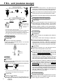
During Use & Maintenance
1. Common
Read instructions and precautions enclosed with
the product before starting use or maintenance.
WARNING
HJXODUO\RQFHRUPRUHLQVL[PRQWKVFKHFNWKHDLU
5
filter and lubricator's plastic bowl for cracks,
damage, and other deterioration.
Cracks, damage or other deterioration could result
in breakage, so if found, replace with a new bowl or
with a metal bowl.
Check the air filter, lubricator plastic bowl, and
lubricator drip window periodically for
contamination.
If parts are heavily contaminated or if transparency has
dropped, replace with a new bowl or drip window.
Use a diluted neutral household detergent to wash parts,
and then rinse well with clean water. Use of other agents
could result in breakage.
HPRYLQ¿OWHUOXEULFDWRUERZO
5
Before removing the bowl, the compressed air,
discharge pressure in the bowl completely, and
FRQ¿UPWKDWQRUHVLGXDOSUHVVXUHUHPDLQV
How to discharge drain
O
S
O
Plastic bowl
S
Metal bowl
(manual cock)
O
S
Metal bowl
(automatic drain)
Drainage is started when the cock is turned to the O side, and the
discharge is stopped when the cock is turned in the S direction.
Tighten in the S direction with your hands.
When the automatic drain is provided, drainage is discharged
automatically when it accumulates. Drainage is also discharged manually.
Removing resin bowl
2000-W, 2500-W, 3000-W, 4000-W, 6000-W, 8000-W Series
Latch
(Press and turn)
CAUTION
Check the oil drip rate once a day.
If the oil drip is faulty, problems could occur in the
unit being lubricated.
Bowl guard
1
2
3
Do not branch the air into lubricating air and oilfree
air with a distributor. The lubricator oil could reverse
ÀRZ
1000-W Series
Body
Clogged filter element will lower performance.
Regularly inspect, clean, and replace the element.
A
Do not disassemble or modify the product.
Bowl guard
1
2
3
16
F.R.L. unit (modular design)
LOPLVW¿OWHU
2
The service lif of the mantle (element) is 1 year (6000 hours) or when
SUHVVXUHGURSVWR03D([FHSWIRUWKH;W\SH5HSODFHWKHPDQWOHZKHQ
life is reached. (Do not touch the urethane foam layer during replacement.)
Removing metal bowl
2000-W, 3000-W, 4000-W, 6000-W, 8000-W Series
Replace the element before the differential pressure indicator
becomes all read if it has an differential pressure indicator.
Latch
(Press and turn)
Mount with zero of the pressure gauge scale facing vertically downward.
1
3
2
5HJXODWRU¿OWHUZLWKUHJXODWRU
5HPRYDORI¿OOLQJSOXJ
3000-W, 4000-W, 8000-W Series
1000-W Series
Filling plug
SHUT
Filling plug
OPEN
With the 1000-W Series,
the pressure in the bowl
is released by sliding
the fill plug 45° in the
OPEN direction.
&ORVHWKH¿OOSOXJDIWHUOXEULFDWLQJ
'R QRW UHPRYH WKH ERZO ZLWKRXW UHPRYLQJ WKH ¿OOLQJ SOXJ
while the bowl is pressurized. (L3000-W to L8000-W)
1HYHUUHPRYHWKHERZOZLWKWKH¿OOLQJSOXJVHWWRWKH6+87VLGHRI
the 1000-W Series (while the bowl is pressurized). (L1000-W)
CAUTION
3XOOWKHSUHVVXUHDGMXVWPHQWNQREDQGUHOHDVHWKHORFN
before setting the regulator pressure. The regulator
could be damaged if the pressure is set without unlock.
Working or piping conditions could cause pulsation.
We recommend changing working conditions or piping by
means such as lowering primary pressure if pulsation occurs.
5. Lubricator
WARNING
Use Class 1 turbine oil (nonadditive) ISO VG32 for
the lubricator.
Use of other oil will result in damage or malfunction.
2. Filter regulator
CAUTION
Element for W1000-W to W8000-W
Inspect the valve assembly when it is removed
during maintenance.
Do not lose internal parts when removing the coil.
HPRYLQJWKHOXEULFDWRU
V¿OOLQJSOXJ
5
7RSUHYHQWWKH¿OOLQJSOXJIURPSRSSLQJRXWORRVHQWKH
filling plug by one turn, and then completely
GHSUHVVXUL]HWKHERZOEHIRUHUHPRYLQJWKH¿OOLQJSOXJ
:LSHDZD\DQ\GLUWDURXQGWKH¿OOSOXJWKDWFRXOGVFDWWHU
CAUTION
Periodically replenish oil in the lubricator bowl so
that it does not drop below the lower limit.
Louver
Spring
Element
3. Filter
WARNING
UDLQVRWKDWDLU¿OWHUGUDLQDJHGRHVQRWDFFXPXODWH
'
EH\RQGWKHPD[LPXP
&RPSRQHQWVFRXOGPDOIXQFWLRQLIGUDLQDJHÀRZVLQWRWKHVHFRQGDU\VLGH
Upper limit of drain
Metal bowl
Upper limit of drain
Metal bowl (M1)
7KHUHVLQERZOPXVWQRWEH¿OOHGPRUHWKDQWKHGUDLQXSSHU
OLPLWRUPD[OHYHOVWDPSHGRQWKHERZOJXDUG
CAUTION
Submicron 0.3 m element
Washing will not restore performance. If the pressure drops to 0.07
03DUHSODFHWKH¿OWHUZLWKDQHZRQH([FOXGLQJ6HULHV
17
When lubricating the L1000-W, pressure in the bowl
is released by turning the fill plug. Refer to the
section on usage and maintenance , above, for
details on using the fill plug. (Lubrication can be
carried out while the pipes are pressurized)
Check that there is no pressure in the bowl, remove the
bowl and bowl guard, and then directly lubricate to the bowl.
Refer to the previous page for details on removing the bowl.
When lubricating the L3000-W to L8000-W, loosen the
¿OO SOXJ VOLJKWO\ WR UHOHDVH SUHVVXUH LQ WKH ERZO WKHQ
UHPRYHWKH¿OOSOXJ5HIHUWRWKHVHFWLRQRQXVDJHDQG
PDLQWHQDQFHDERYHIRUGHWDLOVRQXVLQJWKH¿OOSOXJ
%\UHPRYLQJWKH¿OOLQJSOXJOXEULFDWLRQFDQEHFDUULHGRXWZKLOHWKHSLSHVDUHSUHVVXUL]HG
2LOFDQDOVREHVXSSOLHGIURPWKH¿OOLQJSOXJKROHDQGWKHERZO
can be directly lubricated by removing the bowl and bowl guard.
Refer to the previous page for details on removing the bowl.
With the L8000-W, oil is supplied to the spacer by
OXEULFDWLQJIURPWKH¿OOSOXJKROH
6. Pressure gauge
Check that no impact or vibration is applied directly to the product.
Limit marks will not completely contact each other.
There may be a clearance of 1 scale.
F.R.L. unit (modular design)
6SHFL¿FSUHFDXWLRQV
6SHFL¿FSUHFDXWLRQV)5/FRPSRQHQWV
Chemical resistance of plastic parts
WARNING
The chemical resistance of plastic parts are shown below.
Avoid using products in an atmosphere where chemicals are contained in compressed air, the atmosphere, or where they could adhere to parts.
Use in this state could lead to bowl damage and accidents.
Avoid using these types of chemicals or in an atmosphere containing these chemicals.
A metal bowl is available if these chemicals must be used.
Chemical resistance of plastic bowl and body
Types of chemicals Categories of chemicals
Acid
Inorganic
chemicals
Alkaline
Inorganic salts
Aromatic hydrocarbon
Chlorinated aliphatic
hydrocarbons
Chlorinated aliphatic
hydrocarbons
Petroleum compounds
Alcohol
Phenol
Ether
Organic
chemicals
Ketone
&DUER[\OLFDFLG
Ester
2[RDFLG
Nitro
compounds
Amine
Nitrile
Use a metal bowl in an atmosphere containing the following chemicals.
Check whether the testing solutions, sealing agents and adhesives contain the following chemicals.
Main products containing the chemical
([DPSOHRIJHQHUDOXVDJH
Polycarbonate Nylon
bowl
bowl
Nylon
body
+\GURFKORULGHVXOIXULFDFLGÀXRULQHSKRVSKRULFDFLG Acid washings from metals, acidic degreasing
chromic acid, etc.
solutions, skin treatment solutions
Alkalies such as caustic soda, caustic potash, calcium Alkaline degreasing of metals
Water-based coolant, leakage detection agent
K\GUR[LGHDPPRQLXPZDWHURUVRGLXPFDUERQDWH
Alkalies such as caustic soda, caustic potash, calcium
K\GUR[LGHDPPRQLXPZDWHURUVRGLXPFDUERQDWH
Contained in paint thinner
%HQ]HQHWROXHQH[\OHQHHWK\OEHQ]HQHVW\UHQHHWF
EHQ]HQHWROXHQH[\OHQH
Methyl chloride, ethylene chloride, methylene Organic solvent based washing solution
chloride, acetylene chloride, chloroform, trichylene, for metals (Trichylene, perchloro ethylene,
perchloro ethylene, carbon tetrachloride
carbon tetrachloride)
&KORUREHQ]HQHGLFKORUREHQ]HQHEHQ]HQHKH[DFKORULGH
Chlorinated aromatic
(B,H,C), etc.
Solvent naphtha, gasoline, kerosene
Anti-freeze
0HWKDQROHWKDQROF\FORKH[DQROEHQ]\ODOFRKRO
Leakage detection agent
Carbolic acid, cresold, naphthol, etc.
Antiseptic solution.
Methyl ether, methyl ethyl ether, ethyl ether
Brake oil additive
$FHWRQH PHWK\O HWK\O NHWRQH F\FORKH[DQRQH
acetophenone, etc.
'\HV R[DOLF DFLG IRU DOXPLQXP SURFHVVLQJ
Formic acid, acetic acid, butyl acid, acrylic acid,
phthalic acid for paint base and leak-detection
R[DOLFDFLGSKWKDOLFDFLGHWF
agents e (dowel pin) from rear
Used as an additive for lubricant,
Dimethyl phthalate (DMP), diethyl phthalate (DEP),
synthetic and rust proof oil. Used
dibutyl phthalale (DBP), dioctyl phthalate (DOP)
as a plasticizer for resins.
Glycocholic acid, lactic acid, malic acid, citric acid, tartarate
Nitromethane, nitroethane, nitroethylene,
nitrobenzene, etc.
Methylamine, diethylamine, ethylamine, aniline,
Brake oil additive
acetoacetanilide, etc.
Acetonitrile, acrylonitrile, benznitrile, aceloylidyne
Raw material for nitryl rubber
nitrile, etc.
: Permissible
: Not permissible (plastic will be damaged)
18
F.R.L. unit (modular design)
Precautions for each model
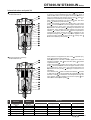
Automatic drain DT3000 DT4000-W Series
Installation & Adjustment
CAUTION
Piping, load torque
Piping screw-in torque
'RQRWDSSO\H[FHVVLYHWRUTXHWRWKHERG\DQGSLSLQJZKHQ
connecting pipes.
3000 4000 Series
0D[WRUTXH1 m
3000 4000 Series
0D[WRUTXH1 m
Make sure that piping load or torque is not applied on the
body or piping.
50
30
During Use & Maintenance
CAUTION
RQRWXVHWKLVSURGXFWZKHUHLWPD\EHVXEMHFWWR
'
direct sunlight and direct UV rays.
The bowl is made of polycarbonate, so avoid using
this product with the following chemicals or in an
atmosphere containing chemicals on page 18. A
metal bowl is available if these chemicals must be
used.
If the drain discharger is installed at a place higher
than the tank's drainage discharge port because
of installation restrictions, the drainage can be
discharged in the following manner.
(1) Let the air bleed by opening the petcock slightly.
(2) Remove the pit cock as shown below, and provide
equalizer piping in the tank.
Use a household-grade neutral detergent to clean
the bowl, then rinse with water.
Use an inner diameter of ø5.7 to ø6.0 or more and
piping of 5 m or less for the drainage section.
SSO\ FRPSUHVVRU RYHU N: ÀRZ RYHU PLQ
$
(NO type automatic drain only)
Repeated sudden increase and decrease of the
pressure will cause the drainage discharger's life to
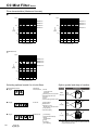
drop. Gradually change the pressure in the circuit.
Do not let in large amount of drain beyond its
capacity. Sudden entry of large amount of drain
may result in malfunctioning.
Precautions for mounting and removing bowl and bowl guard
Service life may shorten drastically in a environment
where large amount of foreign materials enter.
Please conduct maintenance and replace bowl
assembly regularly.
The bowl assembly is an consumable. Replace it
regulary according to conditions and usage.
Mount and remove the bowl and bowl guard after
checking that pressure is not being applied.
Avoid hot air as the life of components will be
shortened, and corrosion could occur.
19
CAUTION
5HVLGXDOSUHVVXUHH[KDXVW
Release residual pressure from the manual cock at the
bottom. When using the metal bowl, release pressure from
the petcock on the side.
5HOHDVHWKHSUHVVXUHDSSOLHGLQWKHERZODQGFRQ¿UPWKDW
there is no pressure.
Attatching and removing
$IWHUFRQ¿UPLQJWKDWWKHUHVLGXDOSUHVVXUHKDVEHHQUHOHDVHG
press down the latch and turn it to lift up the bowl and bowl
guard.
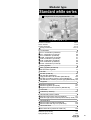
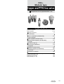
Modular type
Standard white series
Components for air preparation/F.R.L. unit
C O N T E N T S
Product introduction
Series variation
Product description
Safety precautions
Intro 1
1 to 6
7 to 10
11 to 18
Combination
F.R.L. combination (C*000-W)
W.L. combination (C*010-W)
F.R. combination (C*020-W)
F.M.R. combination (C*030-W)
W.M. combination (C*040-W)
R.M. combination (C*050-W)
F.M. combination (C*060-W)
F.F.M. combination (C*070-W)
21
29
35
41
47
53
59
65
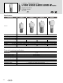
Filter regulator
Filter regulator (W*000-W)
5HYHUVH¿OWHU regulator
69
77
$LU¿OWHU
$LU¿OWHU):
2LOPLVW¿OWHU0:
+LJKSHUIRUPDQFHRLOPLVW¿OWHU0;:
$LU¿OWHUIRUPHGLXPSUHVVXUHW\SH)0:
2LOPLVW¿OWHUIRUPHGLXPSUHVVXUHW\SH00: 165
Regulator
Regulator (R*000-W)
Reverse regulator (R*100-W)
Regulator for medium pressure (RM*000-W)
113
121
171
Lubricator
Lubricator (L*000-W)
129
Mechanical pressure switch
Mechanical pressure switch (P4000-W)
137
Reed switch type compact mechanical pressure switch (P-100-W) 139
Shut-off valve
Shut-off valve (V1000-W V3000-W)
Shut-off valve with key hole (V3010-W)
143
146
Slow start valve
Slow start valve (V3301-W V3321-W)
%UDFNHWMRLQHU%-
Distributor (D*01-00-W)
Piping adaptor (A***-W)
149
153
155
20
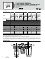
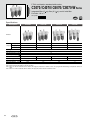
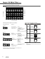
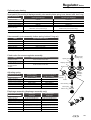
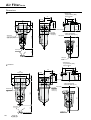
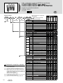
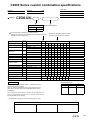
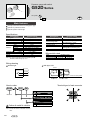
F.R.L. combination standard white series
C1000 / C2000 / C2500-W
C3000 / C4000 / C6500 / C8000-W Series
6SDFHVDYLQJZLWKLQWHJUDWHG¿OWHUUHJXODWRUDQGOXEULFDWRU
Port size: 1/8 to 1
-,6V\PERO
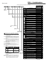
6SHFL¿FDWLRQV
Descriptions
C1000-W
C2000-W
C2500-W
C3000-W
C4000-W
C6500-W
C8000-W
([WHULRU
):
):
):
):
):
):
):
&RPSRQHQWV 5HJXODWRU
$LU¿OWHU
5:
5:
5:
5:
5:
5:
5:
/XEULFDWRU
/:
/:
/:
/:
/:
/:
/:
:RUNLQJÀXLG
&RPSUHVVHGDLU
0D[ZRUNLQJSUHVVXUH 03D
1
:LWKVWDQGLQJSUHVVXUH 03D
$PELHQWWHPSHUDWXUHUDQJH
)LOWUDWLRQUDWLQJ
6HWSUHVVXUHUDQJH
WR
m
03D WR1RWH
0LQLPXPGULSÀRZ1RWH P3PLQ$15
WR
5HOLHI
:LWKUHOLHIPHFKDQLVP
2LOFDSDFLW\
FP3
0$;
'UDLQFDSDFLW\
FP3
12
1RWH
$SSOLFDEOHRLO
3RUWVL]H
7XUELQHRLO&ODVV,629*VSLQGOHRLOFDQQRWEHXVHG
5F137*
XVHVDQDGDSWRU XVHVDQDGDSWRU XVHVDQDGDSWRU XVHVDQDGDSWRU XVHVDQDGDSWRU XVHVDQDGDSWRU XVHVDQDGDSWRU
3URGXFWZHLJKW
NJ
3.64
3UHVVXUHJDXJHEUDFNHWERZOJXDUG
Proded as standard
1RWH7KHPLQLPXPGULSÀRZLVWKDW¿YHGURSVRIWXUELQHRLOGULSSHUPLQXWHDWWKHVHWSUHVVXUHRI03D
1RWH'UDLQDJHDFFXPXODWHVXSWRFP3RQO\ZLWKWKHPDQXDOGUDLQFRFN
Note 3: 7KHDXWRPDWLFGUDLQ
VPLQLPXPRSHUDWLQJSUHVVXUHIRU)RU))ZLWKDQDXWRPDWLFGUDLQLV03D,QLWLDOO\JHQHUDWHGGUDLQDJHDQGDLUDUHSXUJHGXQWLOSUHVVXUHUHDFKHV03D
1RWH7KHDXWRPDWLFGUDLQVPLQLPXPRSHUDWLQJSUHVVXUHIRU)RU))ZLWKDQDXWRPDWLFGUDLQLV03D
1RWH:KHQXVLQJ&:VHULHV)ZLWKDQDXWRPDWLFGUDLQWKHPLQLPXPRSHUDWLQJSUHVVXUHLV03DDQGPD[LPXPRSHUDWLRQSUHVVXUHLV03D
5HIHUWRWKHPD[LPXPZRUNLQJÀRZWDEOHSDJHIRU):)ZLWKDQDXWRPDWLFGUDLQIRUGHWDLOVRQPD[LPXPZRUNLQJÀRZ6HWWKHZRUNLQJÀRZWROHVVWKDQWKHPD[LPXPZRUNLQJÀRZ
Note 6: :KHQHOHPHQWRSWLRQ<LVVHOHFWHGUHIHUWRWKHPD[LPXPZRUNLQJÀRZWDEOHSDJHIRUPD[LPXPÀRZ6HWWKHZRUNLQJÀRZWROHVVWKDQWKHPD[LPXPZRUNLQJÀRZ
1RWH&:6HULHVZLWKDQDXWRPDWLFGUDLQ)PXVWEHXVHGEHORZPD[LPXPÀRZUDWH5HIHUWRSDJH):IRUZHLJKW
,QWHUQDOVWUXFWXUH
)LOWHU
IN
21
5HJXODWRU
/XEULFDWRU
OUT
F.R.L. Combination
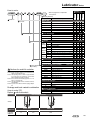
How to order
How to order
5HIHUWRSSDJHIRUDQH[SODQDWLRQRIWKHRSWLRQV
Note 1
&
6\PERO
Model no.
&
A6W
&
U DSV
&
C
&
W
&
6
&
A
C1000
Descriptions
B Port size
A
0RGHOQR
Note 2
B
Port size
6
1/8
8
1/4
10
3/8
15
1/2
20
3/4
25
1
Note 1
& Port thread type
&
3RUWWKUHDGW\SH
Blank
Note 2
Rc thread
N
NPT thread
G
*WKUHDG
D Option
Element Bowl material Drain discharge Note 4
$VVHPEO\DWWDFKPHQW
F
'LVSOD\HGXQLW
*
Piping adaptor
VHWLQFOXGHG
)563/
)5/9.
1RWH,QGLFDWH8'639DQG.ZKHQVHOHFWLQJ
DQDVVHPEO\DWWDFKPHQW
8VH FXVWRP FRPELQDWLRQV VSHFL¿FDWLRQV IRU DQ\ RWKHU
combination.
1RWH$ MRLQHU VHW LV DWWDFKHG ZLWK WKH SLSLQJ DGDSWHU VHW
1RWH,I 137 LV VHOHFWHG IRU WKH & SLSLQJ WKUHDG W\SH D
137SUHVVXUHJDXJHLVHQFORVHG,I5FRU*WKUHDGLV
VHOHFWHGDQ5WKUHDGSUHVVXUHJDXJHLVHQFORVHG
)LOWHUZLWKDXWRPDWLFGUDLQ12W\SHH[KDXVWZLWKRXWSUHVVXUL]DWLRQ
F1 )LOWHUZLWKDXWRPDWLFGUDLQ1&W\SHH[KDXVWZLWKSUHVVXUL]DWLRQ
FF )LOWHUZLWKDXWRPDWLFODUJHGUDLQ12W\SHH[KDXVWZLWKRXWSUHVVXUL]HG
FF1 )LOWHUZLWKDXWRPDWLFODUJHGUDLQ1&W\SHQRH[KDXVWZLWKRXWSUHVVXUL]DWLRQ
Blank 3RO\FDUERQDWHERZO
Z
1\ORQERZO
M
0HWDOERZO
M1 0HWDOERZOZLWKPDQXDOGUDLQFRFN1RWH
Blank ȝP
Y
ȝPVXEPLFURQ
1RWH
Blank :LWKRXWGLIIHUHQWLDOSUHVVXUHGHWHFWLRQSRUW
Blank WR03D
Q
L
:LWKGLIIHUHQWLDOSUHVVXUHGHWHFWLRQSRUW5F
WR03D
1RWH
Blank :LWKUHOLHIPHFKDQLVP
N
1RQUHOLHIW\SH
Blank :LWKVWDQGDUGSUHVVXUHJDXJH*:
T
:LWKRXWSUHVVXUHJDXJHJDXJHSRUW5FDVVHPEOHGVHDOHG
T8 3UHVVXUHJDXJHDWWDFKDEOHJDXJHSRUW5FDVVHPEOHGRSHQ
Blank 6WDQGDUGÀRZOHIWWRULJKW
X1 5HYHUVHÀRZULJKWWROHIW
Assembled
D
Pages 137 to 148, 153, 154
:LWKRXWDVVHPEO\DWWDFKPHQW
:LWKDVVHPEO\DWWDFKPHQW
U
1RWH
'LVWULEXWRU':':':
S
3UHVVXUHVZLWFK3:::
P
3UHVVXUHVZLWFK3:
V
6KXWRIIYDOYH9:9:
K
6KXWRIIYDOYHZLWKNH\KROH9:9:
F Displayed unit
Blank
J1
03DGLVSOD\5FWKUHDG
03DGLVSOD\137*WKUHDG
* Piping adaptor set (included)
Blank
Pages 155 to 157 Note 9
Not attached
A6*W
1/8 piping adaptor set
A8*W
1/4 piping adaptor set
A10*W 3/8 piping adaptor set
A15*W 1/2 piping adaptor set
A20*W 3/4 piping adaptor set
A25*W 1 piping adaptor set
A32*W 1 1/4 piping adaptor set
Adaptor thread type
Symbol Attachment mounting position Applicable model
&:WR&:
&:WR&:
3H[FOXGHV
6HULHV
&:WR&:
9H[FOXGHV6HULHV
.H[FOXGHV6HULHV
/XEULFDWRUZLWKPDQXDOFRFN
F
Blank
1RWH3LSLQJDGDSWRU$:LVDVVHPEOHGRQERWKHQGV
RI&:3LSLQJDGDSWRUVHW$:GRHVQRW
QHHGWREHVSHFL¿HG
1RWH*WKUHDGVDQG137WKUHDGVDUHDYDLODEOHIRU,1287
JDXJH SRUW DQG GUDLQ GLVFKDUJH SRUW PHWDO ERZO ZLWK
DXWRPDWLFGUDLQ$WWDFKPHQW39ZLOOEHVXEMHFWWRWKLV
DVZHOO
1RWH6 HOHFW RSWLRQV IRU HDFK GUDLQDJH GLVFKDUJH ERZO
PDWHULDO HOHPHQW GLIIHUHQWLDO SUHVVXUH GHWHFWLRQ DQG
UHJXODWRU LWHPV :KHQ VHOHFWLQJ RSWLRQV IRU VHYHUDO
LWHPVOLVWRSWLRQVLQRUGHUIURPWKHWRS
1RWH5 HIHU WR SDJH IRU ZRUNLQJ FRQGLWLRQV RI WKH
DXWRPDWLFGUDLQ
1RWH+DYH D FKRLFH GUDLQ GLVFKDUJH RSWLRQ & RU ) DQG
)IRURSWLRQ0
1RWH5HIHUWRSDJHIRUPD[ÀRZUDWHRIRSWLRQ<
1RWH3UHVVXUHJDXJHGLVSOD\UDQJHZLOOEHWR03DIRU
RSWLRQ/
1RWH0RXQWLQJORFDWLRQIRUDVVHPEO\DWWDFKPHQWV
)'5/
C
E Assembly attachment
&DXWLRQVIRUPRGHO1RVHOHFWLRQ
D
S
or
P
9
or
K
Note 3
Blank )LOWHUZLWKPDQXDOGUDLQFRFNOXEULFDWRUZLWKRXWPDQXDOGUDLQFRFN
Differential
pressure
detection
E
Option
Pressure
Flow Pressure
direction gauge Relief range
D
Blank
Rc thread
N
NPT thread
G
*WKUHDG
H Attachment
H Attachment
I
3UHVVXUHJDXJH
RSWLRQDWWDFKHG
Blank
Not attached
PW
3UHVVXUHVZLWFK3:MRLQHUVHW
VW
6KXWRIIYDOYH9:9:MRLQHUVHW
I Pressure gauge option (attached)
Blank
Not attached
G45P
*'3/*'3
G49P
*'3/*'3
G59P
*'3/*'3
G40P
*'3/*'3
G50P
*'3/*'3
G41P
*'3/*'3
G52P
*'3/*'3
Note 10 page 198
22
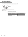
F.R.L. Combination
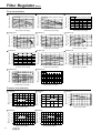
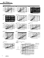
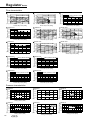
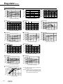
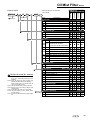
)ORZFKDUDFWHULVWLFV
03D
3ULPDU\SUHVVXUH03D
03D
2
3ULPDU\SUHVVXUH03D
03D
03D
2
3
4
6
8
$LUÀRZUDWHP3PLQ$15
23
3ULPDU\SUHVVXUH03D
$LUÀRZUDWHP3PLQ$15
3ULPDU\SUHVVXUH03D
3ULPDU\SUHVVXUH03D
03D
1
2
3
4
6
8
$LUÀRZUDWHP3PLQ$15
&:
3ULPDU\SUHVVXUH03D
03D
1
3
&:
6HFRQGDU\SUHVVXUH
6HFRQGDU\SUHVVXUH
3ULPDU\SUHVVXUH03D
&:
2
$LUÀRZUDWHP3PLQ$15
&:
03D
1
03D
$LUÀRZUDWHP3PLQ$15
$LUÀRZUDWHP PLQ$15
6HFRQGDU\SUHVVXUH
3ULPDU\SUHVVXUH03D
&:
6HFRQGDU\SUHVVXUH
6HFRQGDU\SUHVVXUH
03D
$LUÀRZUDWHP3PLQ$15
&:
3
3ULPDU\SUHVVXUH03D
$LUÀRZUDWHP3PLQ$15
2
3ULPDU\SUHVVXUH03D
&:
6HFRQGDU\SUHVVXUH
6HFRQGDU\SUHVVXUH
6HFRQGDU\SUHVVXUH
1
&:
2
$LUÀRZUDWHP3PLQ$15
3ULPDU\SUHVVXUH03D
1
03D
3
&:
03D
&:
$LUÀRZUDWHP PLQ$15
$LUÀRZUDWHP3PLQ$15
3
6HFRQGDU\SUHVVXUH
6HFRQGDU\SUHVVXUH
6HFRQGDU\SUHVVXUH
3ULPDU\SUHVVXUH03D
1
&:
$LUÀRZUDWHP PLQ$15
&:
3
$LUÀRZUDWHP PLQ$15
03D
3ULPDU\SUHVVXUH03D
03D
3
6HFRQGDU\SUHVVXUH
3ULPDU\SUHVVXUH03D
6HFRQGDU\SUHVVXUH
03D
&:
&:
6HFRQGDU\SUHVVXUH
6HFRQGDU\SUHVVXUH
&:
3ULPDU\SUHVVXUH03D
03D
1
2
3
4
3
6
8
$LUÀRZUDWHP PLQ$15
1
2
3
4
6
3
8
$LUÀRZUDWHP PLQ$15
0(02
24
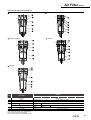
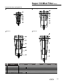
F.R.L. Combination
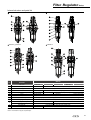
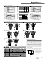
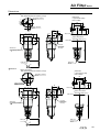
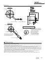
Dimensions
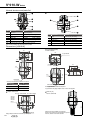
&:
11
36
Q
Attachment
A :SLSLQJDGDSWRUVHW
'UDZLQJRIEUDFNHWVHFWLRQ
OUT
88
IN
P
Port size
5F
5F
Option dimensions
:LWKDXWRPDWLFGUDLQ)
Attachment
SUHVVXUHJDXJH
Inner diameter ø4
VRIWQ\ORQ
WXEH
7XEHFHQWHU
0DLQWHQDQFHGLPHQVLRQV
Drain port
0DLQWHQDQFHGLPHQVLRQV
163
2SWLRQGLPHQVLRQVZLWKSUHVVXUHJDXJHDWWDFKHG
Attached pressure gauge
P
Q
*3
¡
*3
¡
*3
¡
*3
¡
*3
¡
*3
ø42
*3
86
¡
0
Drain port
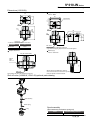
&:
P
163
Q
Attachment
3LSLQJDGDSWRUVHW
IN
OUT
0DLQWHQDQFHGLPHQVLRQV
0DLQWHQDQFHGLPHQVLRQV
Attachment
SUHVVXUHJDXJH
Port size
5F
Rc3/8 2SWLRQGLPHQVLRQVZLWKSUHVVXUHJDXJHDWWDFKHG
Attached pressure gauge
P
Q
*3
¡
,QQHUGLDPHWHU¡WR¡
VRIWQ\ORQWXEH
,QQHUGLDPHWHU¡
VRIWYLQ\OWXEH
*3
¡
*3
¡
*3
ø42
Drain port
*3
¡
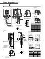
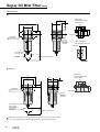
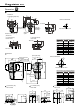
F.R.L. Combination
Dimensions
Dimensions
&:
216
P
63
Attachment
A :SLSLQJDGDSWRUVHW
Q
'UDZLQJRIEUDFNHWVHFWLRQ
OUT
IN
148
,QQHUGLDPHWHU¡WR¡
VRIWQ\ORQWXEH
,QQHUGLDPHWHU¡
6RIWYLQ\OWXEH
Drain port
PDLQWHQDQFHGLPHQVLRQV
Attachment
SUHVVXUHJDXJH
Port size
5F
5F
PDLQWHQDQFHGLPHQVLRQV
14
2SWLRQGLPHQVLRQVZLWKSUHVVXUHJDXJHDWWDFKHG
Attached pressure gauge
P
Q
*3
¡
*3
¡
*3
¡
*3
¡
*3
¡
*3
ø42
*3
¡
&:
14
63
'UDZLQJRIEUDFNHWVHFWLRQ
OUT
148
Attachment
SUHVVXUHJDXJH
,QQHUGLDPHWHU¡WR¡
VRIWQ\ORQWXEH
,QQHUGLDPHWHU¡
VRIWYLQ\OWXEH
Drain port
0DLQWHQDQFHGLPHQVLRQV
HIHU WR SDJH IRU WKH GLPHQVLRQV RI WKH PHWDO ERZO RSWLRQ ILOWHU
5
VHFWLRQDQGSDJHIRUWKHOXEULFDWRUVHFWLRQ
IN
Attachment
A :SLSLQJDGDSWRUVHW
Q
63
P
Port size
5F
5F
0DLQWHQDQFHGLPHQVLRQV
2SWLRQGLPHQVLRQVZLWKSUHVVXUHJDXJHDWWDFKHG
Attached pressure gauge
P
Q
*3
¡
¡
*3
*3
¡
*3
¡
*3
¡
*3
ø42
*3
82
¡
26
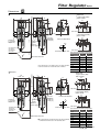
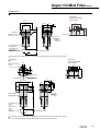
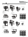
F.R.L. Combination
Dimensions
&:
'UDZLQJRIEUDFNHWVHFWLRQ
OUT
IN
Attachment
SUHVVXUHJDXJH
Port size
5F
5F
5F
5F
,QQHUGLDPHWHU¡WR¡
VRIWQ\ORQWXEH
,QQHUGLDPHWHU¡
VRIWYLQ\OWXEH
0DLQWHQDQFHGLPHQVLRQV
Drain port
Attachment
A :SLSLQJDGDSWRUVHW
Q
14
5F
P
0DLQWHQDQFHGLPHQVLRQV
2SWLRQGLPHQVLRQVZLWKSUHVVXUHJDXJHDWWDFKHG
Attached pressure gauge
P
Q
*3
¡
¡
HIHUWRSDJHIRUWKHGLPHQVLRQVRIWKHPHWDOERZORSWLRQ¿OWHUDQG
5
SDJHIRUWKHOXEULFDWRU
*3
*3
¡
*3
¡
*3
¡
*3
ø42
*3
86
¡
&:
5F
Q
IN
OUT
228
,QQHUGLDPHWHU¡WR¡
VRIWQ\ORQWXEH
,QQHUGLDPHWHU¡
0DLQWHQDQFHGLPHQVLRQV
VRIWYLQ\OWXEH
Drain port
8
Port size
5F
5F
Attachment
SUHVVXUHJDXJH
0DLQWHQDQFHGLPHQVLRQV
14
'UDZLQJRIEUDFNHWVHFWLRQ
㧹㧼㨍
Attachment
A :SLSLQJDGDSWRUVHW
P
2SWLRQGLPHQVLRQVZLWKSUHVVXUHJDXJHDWWDFKHG
Attached pressure gauge
P
Q
*3
¡
¡
*3
*3
82
¡
*3
¡
*3
¡
*3
ø42
*3
¡
F.R.L. Combination
Dimensions with options
Dimensions
&:
5F
14
Attachment
A :SLSLQJDGDSWRUVHW
8
OUT
'UDZLQJRIEUDFNHWVHFWLRQ
Port size
5F
5F
Attachment
SUHVVXUHJDXJH
,QQHUGLDPHWHU¡WR¡
VRIWQ\ORQWXEH
,QQHUGLDPHWHU¡
VRIWYLQ\OWXEH
Drain port
0DLQWHQDQFHGLPHQVLRQV
2SWLRQGLPHQVLRQVZLWKSUHVVXUHJDXJHDWWDFKHG
228
IN
Q
P
Attached pressure gauge
P
Q
*3
¡
*3
¡
*3
¡
*3
¡
*3
¡
*3
ø42
*3
¡
0DLQWHQDQFHGLPHQVLRQV
HIHUWRSDJHIRUWKHGLPHQVLRQVRIWKHPHWDOERZORSWLRQ¿OWHUDQG
5
SDJHIRUWKHOXEULFDWRU
Dimensions with options
A
&:WR&:
Model no.
A
B
&:
B
&:
&:
&:
&:
&:
&:
L1
L2
L3
Assembled options
Model no.
D
S
P
V
K
DS
DP
DV
DK
L1 L2 L3 L1 L2 L3 L1 L2 L3 L1 L2 L3 L1 L2 L3 L1 L2 L3 L1 L2 L3 L1 L2 L3 L1 L2 L3
&:
&:
243 113 226 113 226 113 226 68 148 &:
63 63 63 63 113 63 113 &:
63 63 63 143 63
&:
143 &:Note 1
343 343 143 343 68 148
-
-
-
-
-
-
-
-
-
188
-
-
-
63 113 63 63 63 126 63 126 63
126 63 63 63 &:
-
-
-
-
-
-
-
-
-
-
-
-
&:
-
-
-
-
-
-
-
-
-
-
-
-
Assembled options
Model no.
DSV
DSK
DPV
DPK
SV
SK
PV
PK
L1 L2 L3 L1 L2 L3 L1 L2 L3 L1 L2 L3 L1 L2 L3 L1 L2 L3 L1 L2 L3 L1 L2 L3
&:
136 216
&:
-
-
-
-
-
-
-
-
-
188
-
-
-
-
-
-
-
-
-
&:
63 63 63 63 63 63 63 63 &:
63 63 63 63 63 63 63 332 63 332
&:
223 366 223 366 383 383
&:Note 1
223 223 423 423
&:
-
-
-
-
-
-
-
-
-
-
-
-
-
-
-
-
-
-
&:
-
-
-
-
-
-
-
-
-
-
-
-
-
-
-
-
-
-
L1: 'LPHQVLRQVIURPWKH,1HGJHWRFHQWHURIWKH7W\SHEUDFNHWPRXQWLQJKROH
L2: 6SDFLQJGLPHQVLRQVRIWKHPRXQWLQJKROHIURPWKH¿UVW7W\SHEUDFNHWWRWKHVHFRQG7W\SHEUDFNHW
/'LPHQVLRQVIURPWKH,1HGJHWRWKH287HGJH
5HIHUWRWKHJHQHUDOFDWDORJIRUWKHGHWDLOHGGLPHQWLRQVRIWKHPRXQWLQJKROHRIWKHEUDFNHW
1RWH7KHSLSLQJDGDSWHULVDVVHPEOHGRQWKH287VLGH
3LSLQJDGDSWRU$:LVDVVHPEOHGRQERWKHQGVRI&:
28
F.R.L. combination standard white series
C1010/C2010/C3010/C4010/C8010-W Series
,QWHJUDWHG¿OWHUUHJXODWRUDQGOXEULFDWRU
Port size: 1/8 to 1
-,6V\PERO
6SHFL¿FDWLRQV
Descriptions
C1010-W
C2010-W
C3010-W
C4010-W
C8010-W
)LOWHU UHJXODWRU
::
::
::
::
::
/XEULFDWRU
/:
/:
/:
/:
/:
([WHULRU
&RPSRQHQWV
:RUNLQJÀXLG
&RPSUHVVHGDLU
0D[ZRUNLQJSUHVVXUH 03D
1
:LWKVWDQGLQJSUHVVXUH 03D
$PELHQWWHPSHUDWXUHUDQJH
WR
)LOWUDWLRQUDWLQJ
6HWSUHVVXUHUDQJH
m
03D WR1RWH
0LQLPXPGULSÀRZ1RWH P3PLQ$15
WR
5HOLHI
:LWKUHOLHIPHFKDQLVP
2LOFDSDFLW\
'UDLQFDSDFLW\
FP3
3
12
FP
$SSOLFDEOHRLO
3RUWVL]H
0$;
1RWH
7XUELQHRLO&ODVV,629*VSLQGOHRLOQRWSHUPLWWHG
5F137*
3URGXFWZHLJKW
Standard accessories
NJ
XVHVDQDGDSWRU XVHVDQDGDSWRU XVHVDQDGDSWRU XVHVDQDGDSWRU XVHVDQDGDSWRU
3UHVVXUHJDXJHEUDFNHWERZOJXDUG
1RWH7KHPLQLPXPGULSÀRZLVWKDW¿YHGURSVRIWXUELQHRLOGULSSHUPLQXWHDWWKHVHWSUHVVXUHRI03D
1RWH'UDLQDJHDFFXPXODWHVXSWRFP3RQO\ZLWKWKHPDQXDOGUDLQFRFN
1RWH7KHDXWRPDWLFGUDLQ
VPLQLPXPRSHUDWLQJSUHVVXUHIRU)RU))ZLWKDQDXWRPDWLFGUDLQLV03D,QLWLDOO\JHQHUDWHGGUDLQDJHDQGDLUDUHSXUJHGXQWLO
SUHVVXUHUHDFKHV03D
1RWH7KHDXWRPDWLFGUDLQ
VPLQLPXPRSHUDWLQJSUHVVXUHIRU)RU))ZLWKDQDXWRPDWLFGUDLQLV03D
1RWH:KHQXVLQJ&:6HULHV)ZLWKDQDXWRPDWLFGUDLQWKHPLQLPXPRSHUDWLQJSUHVVXUHLV03DDQGPD[LPXPRSHUDWLRQSUHVVXUHLV03D
5HIHUWRWKHPD[LPXPZRUNLQJÀRZWDEOHSDJHIRU):)ZLWKDQDXWRPDWLFGUDLQIRUGHWDLOVRQPD[LPXPZRUNLQJÀRZ6HWWKHZRUNLQJÀRZ
EHORZWKHPD[LPXPZRUNLQJÀRZ
1RWH:KHQHOHPHQWRSWLRQ<LVVHOHFWHGUHIHUWRWKHPD[LPXPZRUNLQJÀRZWDEOHSDJHIRUPD[LPXPÀRZ6HWWKHZRUNLQJÀRZWROHVVWKDQWKHPD[LPXP
ZRUNLQJÀRZ
1RWH&:6HULHVZLWKDQDXWRPDWLFGUDLQ)PXVWEHXVHGEHORZPD[LPXPÀRZUDWH5HIHUWRSDJH):IRUZHLJKW
W.L. Combination
How to order
How to order
B
B Port size
Port size
&
6
1/8
8
1/4
10
3/8
15
1/2
20
3/4
25
1
Blank
N
NPT thread
*WKUHDG
D Option
Option
Note 3
Blank
Note 4
/XEULFDWRUZLWKPDQXDOFRFN
F
)LOWHUZLWKDXWRPDWLFGUDLQ12W\SHH[KDXVWZLWKRXWSUHVVXUL]DWLRQ
F1
)LOWHUZLWKDXWRPDWLFGUDLQ1&W\SHH[KDXVWZLWKSUHVVXUL]DWLRQ
FF
)LOWHUZLWKDXWRPDWLFODUJHDXWRPDWLFGUDLQ12W\SHH[KDXVWZLWKRXWSUHVVXUL]HG
FF1
Bowl
Z
material
M
M1
Element
Blank
Y
Pressure Blank
L
Range
Blank
Relief
N
Pressure
Blank
T
gauge
F
'LVSOD\HGXQLW
&DXWLRQVIRUPRGHO1RVHOHFWLRQ
1RWH3 LSLQJ DGDSWRU$: LV DVVHPEOHG RQ ERWK HQGV RI
&:3LSLQJDGDSWRUVHW$:GRHVQRWQHHGWREH
VHOHFWHG
1RWH* WKUHDGV DQG 137 WKUHDGV DUH DYDLODEOH IRU ,1 287 JDXJH
SRUWDQGGUDLQGLVFKDUJHSRUWPHWDOERZOZLWKDXWRPDWLFGUDLQ
$WWDFKPHQW39ZLOOEHVXEMHFWWRWKLVDVZHOO
1RWH6 HOHFW RSWLRQV SHU GUDLQDJH ERZO PDWHULDO HOHPHQW DQG
UHJXODWRU VHFWLRQV :KHQ VHOHFWLQJ RSWLRQV IRU VHYHUDO LWHPV
OLVWRSWLRQVLQRUGHUIURPWKHWRS
1RWH5HIHUWRSDJHIRUZRUNLQJFRQGLWLRQVRIWKHDXWRPDWLFGUDLQ
1RWH+DYH D FKRLFH GUDLQ GLVFKDUJH RSWLRQ & RU ) DQG ) IRU
RSWLRQ0
1RWH5HIHUWRSDJHIRUPD[ÀRZUDWHRIRSWLRQ<
1RWH3UHVVXUH JDXJH GLVSOD\ UDQJH ZLOO EH WR 03D IRU RSWLRQ
/
1RWH0RXQWLQJORFDWLRQIRUDVVHPEO\DWWDFKPHQWV
Symbol Installation position of Attachment Applicable model
9RU.
:/9.
&:WR&:
3H[FOXGHV6HULHV
&:WR&:
9H[FOXGHV6HULHV.
H[FOXGHV6HULHV
1RWH,QGLFDWH 8 ' 6 3 9 DQG . ZKHQ VHOHFWLQJ DQ
DVVHPEO\DWWDFKPHQW
8VH FXVWRP FRPELQDWLRQV VSHFLILFDWLRQV IRU DQ\ RWKHU
combination.
1RWH$MRLQHUVHWLVDWWDFKHGZLWKWKHSLSLQJDGDSWHUVHW
1RWH, I 137 LV VHOHFWHG IRU WKH & SLSLQJ WKUHDG W\SH D 137
SUHVVXUHJDXJHLVHQFORVHG,I5FRU*WKUHDGLVVHOHFWHGDQ
5WKUHDGSUHVVXUHJDXJHLVHQFORVHG
T8
)LOWHUZLWKDXWRPDWLFODUJHGUDLQ1&W\SHQRH[KDXVWZLWKRXWSUHVVXUL]DWLRQ
3RO\FDUERQDWHERZO
1\ORQERZO
0HWDOERZO
0HWDOERZOZLWKPDQXDOGUDLQFRFN 1RWH
ȝP
ȝPVXEPLFURQ
1RWH
WR03D
WR03D
1RWH
:LWKUHOLHIPHFKDQLVP
1RQUHOLHIW\SH
6WDQGDUGSUHVVXUHJDXJH*:
:LWKRXWSUHVVXUHJDXJHJDXJHSRUW5FDVVHPEOHGVHDOHG
3UHVVXUHJDXJHDWWDFKDEOHJDXJHSRUW5FDVVHPEOHGRSHQ
Flow
Blank
6WDQGDUGÀRZOHIWWRULJKW
Direction
X1
5HYHUVHÀRZULJKWWROHIW
E Assembly attachment
Page 137 to148, 153, 154
:LWKRXWDVVHPEO\DWWDFKPHQW
Blank
$VVHPEO\DWWDFKPHQWW\SH
U
Assembled
$VVHPEO\DWWDFKPHQW
)LOWHUZLWKPDQXDOGUDLQFRFNOXEULFDWRUZLWKRXWPDQXDOGUDLQFRFN
C
Blank
E
Note 2
Rc thread
G
Drainage
:63/
Note 1
& Port thread type
3RUWWKUHDGW\SH
D
S or P
&
0RGHOQR
&
A
H 3UHVVXUHJDXJHRSWLRQDWWDFKHG
Piping adaptor set
LQFOXGHG
6\PERO
Descriptions
&
A6W
*
&
U SV
W C
6
&
C1010
A Model no.
5HIHUWRSSDJHIRUDQH[SODQDWLRQ
RIWKHRSWLRQV
1RWH
S
3UHVVXUHVZLWFK3:::
P
3UHVVXUHVZLWFK3:
V
6KXWRIIYDOYH9:9:
K
6KXWRIIYDOYHZLWKNH\KROH9:9:
F Displayed unit
Blank
J1
03DGLVSOD\5FWKUHDG
03DGLVSOD\137*WKUHDG
* Piping adaptor set (included)
Blank
Not attached
A6*W
1/8 piping adaptor set
A8*W
1/4 piping adaptor set
A10*W
3/8 piping adaptor set
A15*W
1/2 piping adaptor set
A20*W
3/4 piping adaptor set
A25*W
1 piping adaptor set
A32*W
1 1/4 piping adaptor set
Page 155 to 157 Note 9
* Adaptor thread type
Blank
Rc thread
N
NPT thread
G
*WKUHDG
H Pressure gauge option (attached)
Blank
Not attached
G45P
*'3/*'3
G49P
*'3/*'3
G59P
*'3/*'3
G40P
*'3/*'3
G50P
*'3/*'3
G41P
*'3/*'3
G52P
*'3/*'3
Note 10 Page 198
W.L. Combination
Dimensions
&:
'LPHQVLRQIRUNQRERSHUDWLRQ
Q
11
123
'UDZLQJRIEUDFNHWVHFWLRQ
36
Option dimensions
:LWKDXWRPDWLFGUDLQ)
R
OUT
88
IN
7XEHFHQWHU
Attachment
A :SLSLQJDGDSWRUVHW
Port size
5F
5F
0
Drain port
Attachment
SUHVVXUHJDXJH
Inner diameter ø4
VRIWQ\ORQWXEH
Drain port
2SWLRQGLPHQVLRQVZLWKSUHVVXUHJDXJHDWWDFKHG
Attached pressure gauge
Q
R
*3
¡
*3
¡
*3
¡
*3
¡
*3
¡
*3
ø42
*3
¡
0DLQWHQDQFHGLPHQVLRQV
0DLQWHQDQFHGLPHQVLRQV
&:
P
113
3
Q
OUT
Port size
Drain port
5F
Rc3/8 0DLQWHQDQFHGLPHQVLRQV
,QQHUGLDPHWHU¡WR¡
VRIWQ\ORQWXEH
,QQHUGLDPHWHU¡
VRIWYLQ\OWXEH
0DLQWHQDQFHGLPHQVLRQV
Attachment
SUHVVXUHJDXJH
IN
31
Attachment
3LSLQJDGDSWRUVHW
2SWLRQGLPHQVLRQVZLWKSUHVVXUHJDXJHDWWDFKHG
Attached pressure gauge
P
Q
*3
¡
*3
¡
*3
¡
*3
ø42
*3
¡
W.L. Combination
Dimensions
Dimensions
'LPHQVLRQIRUNQRERSHUDWLRQ
&:
126
63
3
166
Q
14
'UDZLQJRIEUDFNHWVHFWLRQ
R
Attachment
A :SLSLQJDGDSWRUVHW
OUT
148
IN
Port size
5F
5F
Attachment
SUHVVXUHJDXJH
Attached pressure gauge
Q
R
*3
¡
*3
¡
*3
¡
*3
¡
*3
¡
*3
ø42
*3
¡
,QQHUGLDPHWHU¡WR
VRIWQ\ORQWXEH
LQQHUGLDPHWHU¡
VRIWYLQ\OWXEH
Drain port
2SWLRQGLPHQVLRQVZLWKSUHVVXUHJDXJHDWWDFKHG
0DLQWHQDQFHGLPHQVLRQV
0DLQWHQDQFHGLPHQVLRQV
HIHU WR SDJH IRU WKH GLPHQVLRQV RI WKH PHWDO ERZO RSWLRQ ILOWHU
5
UHJXODWRUDQGSDJHIRUWKHOXEULFDWRU
'LPHQVLRQIRUNQRERSHUDWLRQ
Q
3
14
5F
&:
'UDZLQJRIEUDFNHWVHFWLRQ
R
OUT
IN
Attachment
A :SLSLQJDGDSWRUVHW
Attachment
SUHVVXUHJDXJH
Port size
5F
5F
5F
5F
2SWLRQGLPHQVLRQVZLWKSUHVVXUHJDXJHDWWDFKHG
,QQHUGLDPHWHU¡WR
VRIWQ\ORQWXEH
LQQHUGLDPHWHU¡
VRIWYLQ\OWXEH
Drain port
0DLQWHQDQFHGLPHQVLRQV
5HIHU WR SDJH IRU WKH GLPHQVLRQV RI WKH PHWDO ERZO RSWLRQ ILOWHU
UHJXODWRUDQGSDJHIRUWKHOXEULFDWRU
0DLQWHQDQFHGLPHQVLRQV
Attached pressure gauge
Q
R
*3
¡
*3
¡
*3
¡
*3
¡
*3
¡
*3
ø42
*3
¡
32
W.L. Combination
&:
Q
5F
14
8
R
'UDZLQJRIEUDFNHWVHFWLRQ
IN
Port size
5F
5F
OUT
228
Attachment
A :SLSLQJDGDSWRUVHW
4 'LPHQVLRQIRUNQRERSHUDWLRQ
Dimensions
2SWLRQGLPHQVLRQVZLWKSUHVVXUHJDXJHDWWDFKHG
Drain port
0DLQWHQDQFHGLPHQVLRQV
HIHU WR SDJH IRU WKH GLPHQVLRQV RI WKH PHWDO ERZO RSWLRQ ILOWHU
5
UHJXODWRUDQGSDJHIRUWKHOXEULFDWRU
33
Attachment
SUHVVXUHJDXJH
,QQHUGLDPHWHU¡WR
VRIWQ\ORQWXEH
,QQHUGLDPHWHU¡
VRIWYLQ\OWXEH
0DLQWHQDQFHGLPHQVLRQV
Attached pressure gauge
Q
R
*3
¡
*3
¡
*3
¡
*3
¡
*3
¡
*3
ø42
*3
¡
W.L. Combination
Dimensions with options
Dimensions with options
A
&:WR&:
Model no.
A
B
&:
B
&:
&:
&:
&:
L1
L2
L3
Assembled options
Model no.
S
P
V
K
SV
SK
PV
PK
L1 L2 L3 L1 L2 L3 L1 L2 L3 L1 L2 L3 L1 L2 L3 L1 L2 L3 L1 L2 L3 L1 L2 L3
&:
&:
28 63 63 143 143 &:
63 63
63
63 63
63 63 63 63 143 63 143 &:
223 223 &:Note 1
263 &:
-
-
-
-
-
-
-
-
-
-
-
-
68 148
-
-
-
-
-
-
-
-
-
263 343 343
-
-
-
-
-
-
-
-
-
L1: 'LPHQVLRQVIURPWKH,1HGJHWRFHQWHURIWKH7W\SHEUDFNHWPRXQWLQJKROH 5HIHUWRWKHJHQHUDOFDWDORJIRUWKHGHWDLOHGGLPHQWLRQVRIWKHPRXQWLQJKROH
/6SDFLQJGLPHQVLRQVRIWKHPRXQWLQJKROHIURPWKH¿UVW7W\SHEUDFNHW RIWKHEUDFNHW
1RWH7KHSLSLQJDGDSWHULVDVVHPEOHGRQWKH287VLGH
WRWKHVHFRQG7W\SHEUDFNHW
/'LPHQVLRQVIURPWKH,1HGJHWRWKH287HGJH
3LSLQJDGDSWRU$:LVDVVHPEOHGRQERWKHQGVRI&:
34
F.R.L. combination standard white series
C1020 / C2020 / C2520-W
C3020 / C4020 / C6020 / C8020-W Series
,QWHJUDWHG¿OWHUDQGUHJXODWRU
Port size: 1/8 to 1
-,6V\PERO
6SHFL¿FDWLRQV
Descriptions
C1020-W
C2020-W
C2520-W
C3020-W
C4020-W
C6020-W
C8020-W
([WHULRU
&RPSRQHQWV
)LOWHU
):
):
):
):
):
):
):
5HJXODWRU
5:
5:
5:
5:
5:
5:
5:
:RUNLQJÀXLG
&RPSUHVVHGDLU
0D[ZRUNLQJSUHVVXUH 03D
:LWKVWDQGLQJSUHVVXUH 03D
$PELHQWWHPSHUDWXUHUDQJH
WR
)LOWUDWLRQUDWLQJ
6HWSUHVVXUHUDQJH
03D WRNote 2
WR
5HOLHI
:LWKUHOLHIPHFKDQLVP
'UDLQFDSDFLW\
3RUWVL]H
Note 6
m
FP3
12
1RWH
5F137*
XVHVDQDGDSWRU XVHVDQDGDSWRU XVHVDQDGDSWRU XVHVDQDGDSWRU XVHVDQDGDSWRU XVHVDQDGDSWRU XVHVDQDGDSWRU
3URGXFWZHLJKW
Standard accessories
NJ
3UHVVXUHJDXJHEUDFNHWERZOJXDUG
1RWH'UDLQDJHDFFXPXODWHVXSWRFP3RQO\ZLWKWKHPDQXDOGUDLQFRFN
1RWH:KHQXVLQJ&:VHULHV)ZLWKDQDXWRPDWLFGUDLQWKHPLQLPXPRSHUDWLQJSUHVVXUHLV03DDQGPD[LPXPRSHUDWLRQSUHVVXUHLV03D
5HIHUWRWKHPD[LPXPZRUNLQJÀRZWDEOHSDJHIRU))ZLWKDQDXWRPDWLFGUDLQIRUGHWDLOVRQPD[LPXPZRUNLQJÀRZ6HWWKHZRUNLQJÀRZEHORZ
WKHPD[LPXPZRUNLQJÀRZ
1RWH7KHDXWRPDWLFGUDLQ
VPLQLPXPRSHUDWLQJSUHVVXUHIRU)RU))ZLWKDQDXWRPDWLFGUDLQLV03D,QLWLDOO\JHQHUDWHGGUDLQDJHDQGDLUDUHSXUJHGXQWLO
SUHVVXUHUHDFKHV03D
1RWH7KHDXWRPDWLFGUDLQ
VPLQLPXPRSHUDWLQJSUHVVXUHIRU)RU))ZLWKDQDXWRPDWLFGUDLQLV03D
1RWH:KHQHOHPHQWRSWLRQ<LVVHOHFWHGUHIHUWRWKHPD[LPXPZRUNLQJÀRZWDEOHSDJHIRUPD[LPXPÀRZ6HWWKHZRUNLQJÀRZWROHVVWKDQWKHPD[LPXP
ZRUNLQJÀRZ
1RWH7KHZRUNLQJWHPSHUDWXUHUDQJHRIWKHSUHVVXUHVZLWFKZLWKLQGLFDWRU33'DVVHPEO\5LVWR&
1RWH&:6HULHVZLWKDQDXWRPDWLFGUDLQ)PXVWEHXVHGEHORZPD[LPXPÀRZUDWH5HIHUWRSDJH):IRUZHLJKW
F.R. Combination
How to order
&
&
&
A6W
* Piping adaptor
&
U DSV
A Model no.
&
L
5HIHU SDJH IRU DQ H[SODQDWLRQ
of the options.
&
W
&
How to order
C1020 6
VHWLQFOXGHG H 3UHVVXUHJDXJHRSWLRQLQFOXGHG
6\PERO
A 0RGHOQR
Descriptions
B Port size
B Port
size
6
1/8
8
1/4
10
3/8
15
1/2
20
3/4
25
1
Note 1
& Port thread type
& 3RUWWKUHDGW\SH
Blank
N
NPT thread
G
*WKUHDG
D Option
D Option
Note 3
Blank
Drainage
Note 4
F
)LOWHUZLWKDXWRPDWLFGUDLQ1'W\SHH[KDXVWZLWKRXWSUHVVXUL]DWLRQ
)LOWHUZLWKDXWRPDWLFGUDLQ1&W\SHH[KDXVWZLWKSUHVVXUL]DWLRQ
FF
)LOWHUZLWKDXWRPDWLFODUJHDXWRPDWLFGUDLQ12W\SHH[KDXVWZLWKRXWSUHVVXUL]HG
Blank
Bowl
Z
1\ORQERZO
M
0HWDOERZO
Element
Blank
Y
Differential
Blank
pressure detection
Q
Pressure Blank
Range
L
Blank
Relief
N
Blank
&DXWLRQVIRUPRGHO1RVHOHFWLRQ
1RWH3LSLQJ DGDSWRU$: LV DVVHPEOHG RQ ERWK HQGV RI
&:3LSLQJDGDSWRUVHW$:GRHVQRWQHHGWR
EHVSHFL¿HG
1RWH*WKUHDGVDQG137WKUHDGVDUHDYDLODEOHIRU,1287JDXJH
SRUW DQG GUDLQ GLVFKDUJH SRUW PHWDO ERZO ZLWK DXWRPDWLF
GUDLQ$WWDFKPHQW39ZLOOEHVXEMHFWWRWKLVDVZHOO
1RWH6HOHFW RSWLRQV IURP GUDLQ H[KDXVW ERZO PDWHULDO HOHPHQW
GLIIHUHQWLDOSUHVVXUHGHWHFWLRQUHJXODWRUDQGUHJXODWRU:KHQ
VHOHFWLQJRSWLRQVIRUVHYHUDOLWHPVOLVWRSWLRQVLQRUGHUIURP
the top.
1RWH5HIHU WR SDJH IRU ZRUNLQJ FRQGLWLRQV RI WKH DXWRPDWLF
drain.
1RWH5HIHUWRSDJHIRUPD[ÀRZUDWHRIRSWLRQ<
1RWH3UHVVXUHJDXJHGLVSOD\UDQJHZLOOEHWR03DIRURSWLRQ
/
1RWH:KHQRSWLRQ7LVVHOHFWHGRQO\EODQNRU5LVDYDLODEOH
IRU WKH + SUHVVXUH JDXJH HQFORVHG 7KH GLJLWDO SUHVVXUH
VHQVRU33;PRXQWLQJSRUW5FLVDVVHPEOHGYHQWLODWHG
1RWH2XWSXWW\SHZLOOEH131WUDQVLVWRURXWSXW&RQVXOWZLWK&.'
LI313WUDQVLVWRURXWSXWLVUHTXLUHG
1RWH0RXQWLQJORFDWLRQIRUDVVHPEO\DWWDFKPHQWV
Symbol Installation position of Attachment Applicable model
)'5
)563
)59.
&:WR&:
&:WR&:
3H[FOXGHV
6HULHV
&:WR&:
9H[FOXGHV6HULHV
.H[FOXGHV6HULHV
1RWH,QGLFDWH 8 ' 6 3 9 DQG . ZKHQ VHOHFWLQJ DQ
DVVHPEO\DWWDFKPHQW
8VH FXVWRP FRPELQDWLRQV VSHFLILFDWLRQV IRU DQ\ RWKHU
combination.
1RWH$MRLQHUVHWLVDWWDFKHGZLWKWKHSLSLQJDGDSWHUVHW
1RWH,I 137 LV VHOHFWHG IRU WKH & SLSLQJ WKUHDG W\SH D 137
SUHVVXUH JDXJH LV HQFORVHG ,I 5F RU * WKUHDG LV VHOHFWHG
DQ5WKUHDGSUHVVXUHJDXJHLVHQFORVHG
Pressure
gauge
0HWDOERZOZLWKPDQXDOGUDLQFRFN
ȝP
ȝPVXEPLFURQ
1RWH
:LWKRXWGLIIHUHQWLDOSUHVVXUHGHWHFWLRQSRUW
:LWKGLIIHUHQWLDOSUHVVXUHGHWHFWLRQSRUW5F
WR03D
WR03D
1RWH
:LWKUHOLHIPHFKDQLVP
1RQUHOLHIW\SH
6WDQGDUGSUHVVXUHJDXJH*:
T
:LWKRXWSUHVVXUHJDXJHJDXJHSRUW5FDVVHPEOHGVHDOHG
T8
3UHVVXUHJDXJHDWWDFKDEOHJDXJHSRUW5FDVVHPEOHGRSHQ
T6
&RPSDWLELOLW\ZLWKGLJLWDOSUHVVXUHVHQVRU33; 1RWH
R1
Flow
Blank
direction
X1
3UHVVXUHVZLWFKZLWKGLVSOD\33'DVVHPEOHG 1RWH
6WDQGDUGÀRZOHIWWRULJKW
,1287UHYHUVHÀRZULJKWWROHIW
E Assembly attachment
Page 137 to148, 153, 154
:LWKRXWDVVHPEO\DWWDFKPHQW
Blank
$VVHPEO\DWWDFKPHQWW\SH
U
Assembled
F 'LVSOD\HGXQLW
)LOWHUZLWKDXWRPDWLFODUJHGUDLQ1&W\SHQRH[KDXVWZLWKRXWSUHVVXUL]DWLRQ
3RO\FDUERQDWHERZO
material
M1
E $VVHPEO\DWWDFKPHQW
:LWK¿OWHUDQGPDQXDOGUDLQFRFN
F1
FF1
D
S
or
P
9
or
.
Note 2
Rc thread
1RWH
D
'LVWULEXWRU':':':
S
3UHVVXUHVZLWFK3:::
P
3UHVVXUHVZLWFK3:
V
6KXWRIIYDOYH9:9:
K
6KXWRIIYDOYHZLWKNH\KROH9:9:
F Displayed unit
Blank
J1
03DGLVSOD\5FWKUHDG
03DGLVSOD\137*WKUHDG
* Piping adaptor set (included)
Blank
Not attached
A6*W
1/8 piping adaptor set
A8*W
1/4 piping adaptor set
A10*W
3/8 piping adaptor set
A15*W
1/2 piping adaptor set
A20*W
3/4 piping adaptor set
A25*W
1 piping adaptor set
A32*W
1 1/4 piping adaptor set
Page 155 to 157
* Adaptor thread type
Blank
Rc thread
N
NPT thread
G
*WKUHDG
H Pressure gauge option (attached)
Blank
Not attached
G45P
*'3/*'3
G49P
*'3/*'3
G59P
*'3/*'3
G40P
*'3/*'3
G50P
*'3/*'3
G41P
*'3/*'3
G52P
R2
Note 6
Note 11 Page 198
*'3/*'3
'LJLWDOSUHVVXUHVHQVRU33;510
36
F.R. Combination
Dimensions
&:
11
123
36
'UDZLQJRIEUDFNHWVHFWLRQ
P
Attachment
A :SLSLQJDGDSWRUVHW
Port size
Option dimensions
:LWKDXWRPDWLFGUDLQ)
287
IN
7XEHFHQWHU
5F
5F
Attachment
SUHVVXUHJDXJH
With PPD
option
Inner diameter ø4
VRIWQ\ORQWXEH
Drain port
0
Drain port
0DLQWHQDQFHGLPHQVLRQV
2SWLRQGLPHQVLRQVZLWKSUHVVXUHJDXJHDWWDFKHG
O
P
*3
Attached pressure gauge
¡
*3
¡
*3
¡
*3
¡
*3
¡
*3
ø42
*3
¡
R2
&:
P
Attachment
SLSLQJDGDSWRUVHW
Q
IN
287
5F
5F
Attachment
SUHVVXUHJDXJH
Port size
0DLQWHQDQFHGLPHQVLRQV
2SWLRQGLPHQVLRQVZLWKSUHVVXUHJDXJHDWWDFKHG
,QQHUGLDPHWHU¡WR¡
VRIWQ\ORQWXEH
,QQHUGLDPHWHU¡
VRIWYLQ\OWXEH
Drain port
Attached pressure gauge
P
Q
*3
¡
*3
¡
*3
¡
*3
ø42
*3
¡
R2
F.R. Combination
Dimensions
Dimensions
&:
14
113
Attachment
A :SLSLQJDGDSWRUVHW
63
287
P
IN
'UDZLQJRIEUDFNHWVHFWLRQ
148
Port size
5F
5F
2SWLRQGLPHQVLRQVZLWKSUHVVXUHJDXJHDWWDFKHG
Attachment
SUHVVXUHJDXJH
With PPD
option
PDLQWHQDQFHGLPHQVLRQV
,QQHUGLDPHWHU¡WR
VRIWQ\ORQWXEH
,QQHUGLDPHWHU¡
VRIWYLQ\OWXEH
Drain port
Attached pressure gauge
O
P
*3
¡
*3
¡
*3
¡
*3
¡
*3
¡
*3
ø42
*3
¡
R2
&:
14
126
63
P
Attachment
A :SLSLQJDGDSWRUVHW
166
'UDZLQJRIEUDFNHWVHFWLRQ
IN
287
Port size
With PPD
option
2SWLRQGLPHQVLRQVZLWKSUHVVXUHJDXJHDWWDFKHG
Attached pressure gauge
,QQHUGLDPHWHU¡WR
VRIWQ\ORQWXEH
,QQHUGLDPHWHU¡
VRIWYLQ\OWXEH
Drain port
5F
5F
148
Attachment
SUHVVXUHJDXJH
0DLQWHQDQFHGLPHQVLRQV
5HIHUWRSDJHIRUGLPHQVLRQVRIWKHPHWDOERZORSWLRQ
O
P
*3
¡
*3
¡
*3
¡
*3
¡
*3
¡
*3
ø42
*3
¡
R2
38
F.R. Combination
Dimensions
&:
5F
14
Attachment
A :SLSLQJDGDSWRUVHW
P
287
IN
'UDZLQJRIEUDFNHWVHFWLRQ
Port size
5F
5F
5F
5F
With PPD
option
2SWLRQGLPHQVLRQVZLWKSUHVVXUHJDXJHDWWDFKHG
Attached pressure gauge
,QQHUGLDPHWHU¡WR
VRIWQ\ORQWXEH
,QQHUGLDPHWHU¡
VRIWYLQ\OWXEH
Drain port
Attachment
SUHVVXUHJDXJH
0DLQWHQDQFHGLPHQVLRQV
5HIHUWRSDJHIRUGLPHQVLRQVRIWKHPHWDOERZORSWLRQ
O
P
*3
¡
*3
¡
*3
¡
*3
¡
*3
¡
*3
ø42
*3
¡
R2
&:
5F
Attachment
A :SLSLQJDGDSWRUVHW
287
㧹㧼㨍
Port size
Attachment
3UHVVXUHJDXJH
With PPD
option
5F
5F
0DLQWHQDQFHGLPHQVLRQV
'UDZLQJRIEUDFNHWVHFWLRQ
8
P
IN
14
,QQHUGLDPHWHU¡WR
VRIWQ\ORQWXEH
,QQHUGLDPHWHU¡
VRIWYLQ\OWXEH
Drain port
2SWLRQGLPHQVLRQVZLWKSUHVVXUHJDXJHDWWDFKHG
Attached pressure gauge
O
P
*3
¡
*3
¡
*3
¡
*3
¡
*3
¡
*3
ø42
*3
¡
R2
F.R. Combination
Dimensions with options
Dimensions
&:
5F
14
62
8
P
Attachment
A :SLSLQJDGDSWRUVHW
287
IN
Attachment
SUHVVXUHJDXJH
5F
5F
2SWLRQGLPHQVLRQVZLWKSUHVVXUHJDXJHDWWDFKHG
'UDZLQJRIEUDFNHWVHFWLRQ
Port size
Attached pressure gauge
With PPD
option
,QQHUGLDPHWHU¡WR
VRIWQ\ORQWXEH
,QQHUGLDPHWHU¡
VRIWYLQ\OWXEH
Drain port
0DLQWHQDQFHGLPHQVLRQV
5HIHUWRSDJHIRUGLPHQVLRQVRIWKHPHWDOERZORSWLRQ
O
P
*3
¡
*3
¡
*3
¡
*3
¡
*3
¡
*3
ø42
*3
¡
R2
Dimensions with options
Model no.
A
B
&:
A
&: &:
&:
&:
B
&:
&:
&:
&:
L1
L2
L3
Assembled options
D
S (Note 1)
P
V
K
DS (Note 1)
DP
DV
DK
Model no.
L1 L2 L3 L1 L2 L3 L1 L2 L3 L1 L2 L3 L1 L2 L3 L1 L2 L3 L1 L2 L3 L1 L2 L3 L1 L2 L3
&:
&:
28 163 163 183 &:
63 63
63
63
63
63 63 63 63 &:
63 63
63 63
63
63
63 63
63 63 63 63 63 &:
223 223 243 &:Note 1
263 &:
í
í
í
í
í
í
í
í
í
í
í
í
&:
í
í
í
í
í
í
í
í
í
í
í
í
í
í
í
í
í
í
68 í
í
í
68 148
í
í
í
263 263 Assembled options
DSV
DSK
DPV
DPK
SV
SK
PV
PK
Model no.
L1 L2 L3 L1 L2 L3 L1 L2 L3 L1 L2 L3 L1 L2 L3 L1 L2 L3 L1 L2 L3 L1 L2 L3
&:
&:
113 226
í
í
í
í
í
í
í
í
í
&:
63 113 63 113 63 162 63 162 63 63 63 63 68 148
í
í
í
í
í
í
í
í
í
113 226 162 162 243 243
&:
63 126 63 126 63 63 63 63 63 143 63 143 &:
143 286 143 286 &:Note 1
143 326 143 326 343 343
&:
í
í
í
í
í
í
í
í
í
í
í
í
í
í
í
í
í
í
&:
í
í
í
í
í
í
í
í
í
í
í
í
í
í
í
í
í
í
L1: 'LPHQVLRQVIURPWKH,1HGJHWRFHQWHURIWKH7W\SHEUDFNHWPRXQWLQJKROH
L2: 6SDFLQJGLPHQVLRQVRIWKHPRXQWLQJKROHIURPWKH¿UVW7W\SHEUDFNHWWRWKHVHFRQG7W\SHEUDFNHW
/'LPHQVLRQVIURPWKH,1HGJHWRWKH287HGJH
5HIHUWRWKHJHQHUDOFDWDORJIRUWKHGHWDLOHGGLPHQWLRQVRIWKHPRXQWLQJKROHRIWKHEUDFNHW
1RWH7KHSLSLQJDGDSWHULVDVVHPEOHGRQWKH287VLGH
3LSLQJDGDSWRU$:LVDVVHPEOHGRQERWKHQGVRI&:
)05FRPELQDWLRQVWDQGDUGZKLWHVHULHV
C1030 / C2030 / C2530-W
C3030 / C4030 / C6030 / C8030-W Series
,QWHJUDWHG¿OWHURLOPLVW¿OWHUDQGUHJXODWRU
Port size: 1/8 to 1
-,6V\PERO
6SHFL¿FDWLRQV
Descriptions
C1030-W
C2030-W
C2530-W
C3030-W
C4030-W
C6030-W
C8030-W
([WHULRU
)LOWHU
&RPSRQHQWV 2LOPLVW¿OWHU
5HJXODWRU
):
):
):
):
):
):
):
0:
0:
0:
0:
0:
0:
0:
5:
5:
5:
5:
5:
5:
5:
:RUNLQJÀXLG
&RPSUHVVHGDLU
0D[ZRUNLQJSUHVVXUH 03D
1
:LWKVWDQGLQJSUHVVXUH 03D
$PELHQWWHPSHUDWXUHUDQJH
6HWSUHVVXUHUDQJH
WR
03D WR1RWH
5HOLHI
3RUWVL]H
Note 6
WR
:LWKUHOLHIPHFKDQLVP
5F137*
XVHVDQDGDSWRU XVHVDQDGDSWRU XVHVDQDGDSWRU XVHVDQDGDSWRU XVHVDQDGDSWRU XVHVDQDGDSWRU XVHVDQDGDSWRU
3URGXFWZHLJKW
NJ
6HFRQGDU\RLOFRQFHQWUDWLRQ
1.86
2.6
PJP3RUOHVV
2LOPLVW¿OWHURXWOHWVLGH
0D[LPXPÀRZUDWH1RWH P3/min
1RWH7KHPD[LPXPÀRZLVIRUDSULPDU\SUHVVXUHRI03D:KHQHOHPHQWRSWLRQ<LVVHOHFWHGUHIHUWRSDJHIRUPD[LPXPÀRZ
1RWH5HIHUWRSDJHIRUGHWDLOVRQRWKHURLOPLVW¿OWHUV
1RWH:KHQ)ZLWKDQDXWRPDWLFGUDLQLVVHOHFWHGWKHVXSSO\DLUSUHVVXUHLV03DRUPRUH$LU¿OWHUDQGDXWRPDWLFGUDLQDUHSXUJHGZLWKLQLWLDOGUDLQDJH
XQWLOSUHVVXUHUHDFKHV03D
1RWH:KHQ)ZLWKDQDXWRPDWLFGUDLQLVVHOHFWHGWKH¿OWHURLOPLVW¿OWHUDQG1&DXWRPDWLFGUDLQDUHDVVHPEOHGEXWWKHVXSSO\DLUSUHVVXUHPXVWEH
03DRUPRUH
1RWH:KHQ)ZLWKDQDXWRPDWLFGUDLQLVVHOHFWHGIRUWKH&:VHULHVWKH1&DXWRPDWLFGUDLQLVDVVHPEOHGIRUERWKWKH¿OWHUDQGRLOPLVW¿OWHU0LQLPXP
RSHUDWLRQSUHVVXUHLV03DDQGPD[LPXPRSHUDWLRQSUHVVXUHLV03D5HIHUWRWKHPD[LPXPSURFHVVLQJÀRZWDEOHSDJHIRUWKH0:)
DXWRPDWLFGUDLQIRUWKHPD[LPXPZRUNLQJÀRZ
1RWH7KHZRUNLQJWHPSHUDWXUHUDQJHRIWKHSUHVVXUHVZLWFKZLWKLQGLFDWRU33'DVVHPEO\5LVWR&
41
F.M.R. Combination
How to order
&
&
* Piping adaptor
A Model no.
&
5HIHU SDJH IRU DQ H[SODQDWLRQ
of the options.
A6W
&
U DSV
&
L
&
W
&
How to order
C1030 6
VHWLQFOXGHG H 3UHVVXUHJDXJHRSWLRQDWWDFKHG
6\PERO
A 0RGHOQR
Descriptions
B Port size
B Port
size
6
1/8
8
1/4
10
3/8
15
1/2
20
3/4
25
1
Note 1
& Port thread type
& 3RUWWKUHDGW\SH
Blank
Note 2
Rc thread
N
NPT thread
G
*WKUHDG
D Option
D Option
Note 3
Blank
F
$XWRPDWLFGUDLQZLWKPDQXDORYHUULGH12W\SHH[KDXVWVZLWKRXWSUHVVXUL]DWLRQ
Drainage
F1
$XWRPDWLFGUDLQZLWKPDQXDORYHUULGH1&W\SHQRH[KDXVWZLWKRXWSUHVVXUL]DWLRQ
Note 4, Note 5
FF
/DUJHH[KDXVWDXWRPDWLFGUDLQZLWKPDQXDORYHUULGH12W\SHH[KDXVWVZLWKRXWSUHVVXUL]DWLRQ
FF1
/DUJHH[KDXVWDXWRPDWLFGUDLQZLWKPDQXDORYHUULGH12W\SHQRH[KDXVWZLWKRXWSUHVVXUL]DWLRQ
Blank
material
1\ORQERZO
M
0HWDOERZO
M1
E $VVHPEO\DWWDFKPHQW
Element
1RWH3LSLQJ DGDSWRU$: LV DVVHPEOHG RQ ERWK HQGV RI
&:3LSLQJDGDSWRUVHW$:GRHVQRWQHHGWR
EHVSHFL¿HG
1RWH*WKUHDGVDQG137WKUHDGVDUHDYDLODEOHIRU,1287JDXJH
SRUW DQG GUDLQ GLVFKDUJH SRUW PHWDO ERZO ZLWK DXWRPDWLF
GUDLQ$WWDFKPHQW39ZLOOEHVXEMHFWWRWKLVDVZHOO
1RWH6HOHFW RSWLRQV IURP GUDLQ H[KDXVW ERZO PDWHULDO HOHPHQW
GLIIHUHQWLDOSUHVVXUHGHWHFWLRQUHJXODWRUDQGUHJXODWRU:KHQ
VHOHFWLQJRSWLRQVIRUVHYHUDOLWHPVOLVWRSWLRQVLQRUGHUIURP
the top.
1RWH5HIHU WR SDJH IRU ZRUNLQJ FRQGLWLRQV RI WKH DXWRPDWLF
drain.
1RWH:KHQRSWLRQV\PERO)LVVHOHFWHGWKH12DXWRPDWLFGUDLQ
LV HQFORVHG IRU WKH DLU ¿OWHU DQG WKH 1& DXWRPDWLF GUDLQ IRU
WKHRLOPLVW¿OWHU
)) DQG )) KDV D ODUJH GUDLQ W\SH RLO PLVW ¿OWHU EXW WKH
DXWRPDWLFGUDLQLVVDPHDVWKH1&W\SH
1RWH5HIHUWRSDJHIRUPD[ÀRZUDWHRIRSWLRQ<
1RWH3UHVVXUHJDXJHGLVSOD\UDQJHZLOOEHWR03DIRURSWLRQ
/
1RWH:KHQRSWLRQ7LVVHOHFWHGRQO\EODQNRU5LVVHOHFWHG
IRU WKH + SUHVVXUH JDXJH HQFORVHG 7KH GLJLWDO SUHVVXUH
VHQVRU33;PRXQWLQJSRUW5FLVDVVHPEOHGYHQWLODWHG
1RWH2XWSXWW\SHZLOOEH131WUDQVLVWRURXWSXW&RQVXOWZLWK&.'
LI313WUDQVLVWRURXWSXWLVUHTXLUHG
1RWH0RXQWLQJORFDWLRQIRUDVVHPEO\DWWDFKPHQWV
Symbol Installation position of Attachment Applicable model
D
S
or
P
9
or
.
)0'5
)0563
)059.
&:WR&:
&:WR&:
3H[FOXGHV
6HULHV
&:WR&:
9H[FOXGHV6HULHV
.H[FOXGHV6HULHV
1RWH,QGLFDWH8'639DQG.ZKHQVHOHFWLQJDQ
DVVHPEO\DWWDFKPHQW
8VH FXVWRP FRPELQDWLRQV VSHFLILFDWLRQV IRU DQ\ RWKHU
combination.
1RWH$MRLQHUVHWLVDWWDFKHGZLWKWKHSLSLQJDGDSWHUVHW
1RWH,I 137 LV VHOHFWHG IRU WKH & SLSLQJ WKUHDG W\SH D 137
SUHVVXUH JDXJH LV HQFORVHG ,I 5F RU * WKUHDG LV VHOHFWHG
DQ5WKUHDGSUHVVXUHJDXJHLVHQFORVHG
Blank
Y
0HWDOERZOZLWKPDQXDOGUDLQFRFN
ȝP
ȝPVXEPLFURQ
1RWH
Differential
Blank
:LWKRXWGLIIHUHQWLDOSUHVVXUHGHWHFWLRQSRUW
pressure detection
Q
:LWKGLIIHUHQWLDOSUHVVXUHGHWHFWLRQSRUW5F
Pressure Blank
L
Range
Blank
Relief
N
Blank
WR03D
WR03D
1RWH
:LWKUHOLHIPHFKDQLVP
1RQUHOLHIW\SH
6WDQGDUGSUHVVXUHJDXJH*:
T
:LWKRXWSUHVVXUHJDXJHJDXJHSRUW5FDVVHPEOHGVHDOHG
T8
3UHVVXUHJDXJHDWWDFKDEOHJDXJHDWFKPHQWSRUW5FDVVHPEOHGRSHQ
T6
&RPSDWLELOLW\ZLWKGLJLWDOSUHVVXUHVHQVRU33; 1RWH
R1
3UHVVXUHVZLWFKZLWKGLVSOD\33'DVVHPEOHG 1RWH
Pressure
gauge
Flow
Blank
6WDQGDUGÀRZOHIWWRULJKW
Direction
X1
5HYHUVHÀRZULJKWWROHIW
E Assembly attachment
Pages 137 to 148, 153, 154
:LWKRXWDVVHPEO\DWWDFKPHQW
Blank
$VVHPEO\DWWDFKPHQWW\SH
U
Assembled
&DXWLRQVIRUPRGHO1RVHOHFWLRQ
3RO\FDUERQDWHERZO
Z
Bowl
F 'LVSOD\HGXQLW
:LWKPDQXDOGUDLQFRFN
1RWH
D
'LVWULEXWRU':':':
S
3UHVVXUHVZLWFK3:::
P
3UHVVXUHVZLWFK3:
V
6KXWRIIYDOYH9:9:
K
6KXWRIIYDOYHZLWKNH\KROH9:9:
F Displayed unit
Blank
J1
03DGLVSOD\5FWKUHDG
03DGLVSOD\137*WKUHDG
* Piping adaptor set (included)
Blank
Not attached
A6*W
1/8 piping adaptor set
A8*W
1/4 piping adaptor set
A10*W
3/8 piping adaptor set
A15*W
1/2 piping adaptor set
A20*W
3/4 piping adaptor set
A25*W
1 piping adaptor set
A32*W
1 1/4 piping adaptor set
Pages 155 to 157 Note 11
* Adaptor thread type
Blank
Rc thread
N
NPT thread
G
*WKUHDG
H Pressure gauge option (attached)
Blank
Not attached
G45P
*'3/*'3
G49P
*'3/*'3
G59P
*'3/*'3
G40P
*'3/*'3
G50P
*'3/*'3
G41P
*'3/*'3
G52P
R2
Note 7
Note 12 Page 198
*'3/*'3
'LJLWDOSUHVVXUHVHQVRU33;510
42
F.M.R. Combination
Dimensions
&:
11
163
36
P
Attachment
A :SLSLQJDGDSWRUVHW
287
IN
5F
5F
7XEHFHQWHU
Attachment
SUHVVXUHJDXJH
'UDZLQJRIEUDFNHWVHFWLRQ
Option dimensions
:LWKDXWRPDWLFGUDLQ)
Port size
With PPD
option
Inner diameter ø4
VRIWQ\ORQWXEH
Drain port
0
Drain port
0DLQWHQDQFHGLPHQVLRQV
2SWLRQGLPHQVLRQVZLWKSUHVVXUHJDXJHDWWDFKHG
Attached pressure gauge
&:
O
P
*3
¡
*3
¡
*3
¡
*3
¡
*3
¡
*3
ø42
*3
¡
R2
P
Q
Attachment
SLSLQJDGDSWRUVHW
287
IN
5F
Rc3/8 Attachment
SUHVVXUHJDXJH
Port size
43
0DLQWHQDQFHGLPHQVLRQV
2SWLRQGLPHQVLRQVZLWKSUHVVXUHJDXJHDWWDFKHG
Attached pressure gauge
P
Q
*3
¡
,QQHUGLDPHWHU¡WR¡
VRIWQ\ORQWXEH
,QQHUGLDPHWHU¡
VRIWYLQ\OWXEH
*3
¡
*3
¡
*3
ø42
Drain port
*3
¡
R2
F.M.R. Combination
Dimensions
Dimensions
&:
14
216
63
Attachment
A :SLSLQJDGDSWRUVHW
63
287
P
IN
'UDZLQJRIEUDFNHWVHFWLRQ
Port size
5F
5F
148
Attachment
SUHVVXUHJDXJH
With PPD
option
2SWLRQGLPHQVLRQVZLWKSUHVVXUHJDXJHDWWDFKHG
Attached pressure gauge
O
P
*3
¡
*3
¡
*3
¡
*3
¡
*3
¡
*3
ø42
*3
¡
R2
PDLQWHQDQFHGLPHQVLRQV
,QQHUGLDPHWHU¡WR
VRIWQ\ORQWXEH
LQQHUGLDPHWHU¡
VRIWYLQ\OWXEH
Drain port
&:
14
63
63
P
287
IN
Attachment
SUHVVXUHJDXJH
'UDZLQJRIEUDFNHWVHFWLRQ
Port size
24'55
6740
24'55
6740
148
Attachment
A :SLSLQJDGDSWRUVHW
5F
5F
With PPD
option
2SWLRQGLPHQVLRQVZLWKSUHVVXUHJDXJHDWWDFKHG
,QQHUGLDPHWHU¡WR
VRIWQ\ORQWXEH
,QQHUGLDPHWHU¡
VRIWYLQ\OWXEH
Drain port
0DLQWHQDQFHGLPHQVLRQV
5HIHUWRSDJHIRUWKHGLPHQVLRQVRIWKHPHWDOERZORSWLRQ¿OWHUDQG
SDJHIRUWKHRLOPLVW¿OWHU
O
P
*3
Attached pressure gauge
¡
*3
¡
*3
¡
*3
¡
*3
¡
*3
ø42
*3
¡
R2
44
F.M.R. Combination
Dimensions
&:
5F
O
'UDZLQJRIEUDFNHWVHFWLRQ
14
P
287
IN
Port size
Attachment
SUHVVXUHJDXJH
24'55
6740
5F
5F
5F
24'55
6740
Attachment
A :SLSLQJDGDSWRUVHW
With PPD
option
,QQHUGLDPHWHU¡WR
VRIWQ\ORQWXEH
,QQHUGLDPHWHU¡
VRIWYLQ\OWXEH
Drain port
2SWLRQGLPHQVLRQVZLWKSUHVVXUHJDXJHDWWDFKHG
0DLQWHQDQFHGLPHQVLRQV
Attached pressure gauge
5HIHUWRSDJHIRUWKHGLPHQVLRQVRIWKHPHWDOERZORSWLRQ¿OWHUDQG
SDJHIRUWKHRLOPLVW¿OWHU
&:
O
P
*3
¡
*3
¡
*3
¡
*3
¡
*3
¡
*3
ø42
*3
¡
R2
8
14
Rc1 1/4: 346
O
'UDZLQJRIEUDFNHWVHFWLRQ
Attachment
A :SLSLQJDGDSWRUVHW
P
Port size
5F
5F
287
㧹㧼㨍
2SWLRQGLPHQVLRQVZLWKSUHVVXUHJDXJHDWWDFKHG
,QQHUGLDPHWHU¡WR
VRIWQ\ORQWXEH
,QQHUGLDPHWHU¡
VRIWYLQ\OWXEH
Drain port
Attachment
SUHVVXUHJDXJH
With PPD
option
IN
0DLQWHQDQFHGLPHQVLRQV
Attached pressure gauge
O
P
*3
¡
*3
¡
*3
¡
*3
¡
*3
¡
*3
ø42
*3
¡
R2
F.M.R. Combination
Dimensions with options
Dimensions
62
Attachment
A :SLSLQJDGDSWRUVHW
8
P
14
287
IN
5F
O
&:
'UDZLQJRIEUDFNHWVHFWLRQ
Attachment
SUHVVXUHJDXJH
With PPD
Option
Port size
5F
5F
2SWLRQGLPHQVLRQVZLWKSUHVVXUHJDXJHDWWDFKHG
Attached pressure gauge
,QQHUGLDPHWHU¡WR
VRIWQ\ORQWXEH
,QQHUGLDPHWHU¡
VRIWYLQ\OWXEH
Drain port
0DLQWHQDQFHGLPHQVLRQV
5HIHUWRSDJHIRUWKHGLPHQVLRQVRIWKHPHWDOERZORSWLRQ¿OWHUDQG
SDJHIRUWKHRLOPLVW¿OWHU
O
P
*3
¡
*3
¡
*3
¡
*3
¡
*3
¡
*3
ø42
*3
¡
R2
Dimensions with options
A
&:WR&:
Model no.
A
B
&:
B
&:
&:
PRESS
TURN
&:
&:
&:
&:
L1
L2
L3
Assembled options
D
S (Note 1)
P
V
K
DS (Note 1)
DP
DV
DK
Model no.
L1 L2 L3 L1 L2 L3 L1 L2 L3 L1 L2 L3 L1 L2 L3 L1 L2 L3 L1 L2 L3 L1 L2 L3 L1 L2 L3
&:
&:
113 113 113 213 113 213 233 68 148 í
í
í
í
í
í
í
í
í
188
í
í
í
&:
63 63 113 63 113 63 113 63 113 63 63 63 63 &:
63 63 126 63 126 63 126 63 126 63 63 63 63 &:
323 &:Note 1
343 343 343 &:
í
í
í
í
í
í
í
í
í
í
í
í
&:
í
í
í
í
í
í
í
í
í
í
í
í
Assembled options
DSV
DSK
DPV
DPK
SV
SK
PV
PK
Model no.
L1 L2 L3 L1 L2 L3 L1 L2 L3 L1 L2 L3 L1 L2 L3 L1 L2 L3 L1 L2 L3 L1 L2 L3
&:
136 216
&:
í
í
í
í
í
í
í
í
í
188
í
í
í
í
í
í
í
í
í
&:
63 63 63 63 63 63 63 63 &:
63 63 63 238 364 63 238 364 63 63 63 332 63 332
&:
223 366 223 366 383 383
&:Note 1
223 223 423 423
&:
í
í
í
í
í
í
í
í
í
í
í
í
í
í
í
í
í
í
&:
í
í
í
í
í
í
í
í
í
í
í
í
í
í
í
í
í
í
L1: 'LPHQVLRQVIURPWKH,1HGJHWRFHQWHURIWKH7W\SHEUDFNHWPRXQWLQJKROH
L2: 6SDFLQJGLPHQVLRQVRIWKHPRXQWLQJKROHIURPWKH¿UVW7W\SHEUDFNHWWRWKHVHFRQG7W\SHEUDFNHW
/'LPHQVLRQVIURPWKH,1HGJHWRWKH287HGJH
*5HIHUWRWKHJHQHUDOFDWDORJIRUWKHGHWDLOHGGLPHQWLRQVRIWKHPRXQWLQJKROHRIWKHEUDFNHW
1RWH7KHSLSLQJDGDSWHULVDVVHPEOHGRQWKH287VLGH
3LSLQJDGDSWRU$:LVDVVHPEOHGRQERWKHQGVRI&:
46
:0FRPELQDWLRQVWDQGDUGZKLWHVHULHV
C1040/C2040/C3040/C4040/C8040-W Series
,QWHJUDWHG¿OWHURLOPLVW¿OWHUDQGUHJXODWRU
Port size: 1/8 to 1
-,6V\PERO
6SHFL¿FDWLRQV
Descriptions
C1040-W
C2040-W
C3040-W
C4040-W
C8040-W
)LOWHU UHJXODWRU
::
::
::
::
::
2LOPLVW¿OWHU
0:
0:
0:
0:
0:
([WHULRU
&RPSRQHQWV
:RUNLQJÀXLG
&RPSUHVVHGDLU
0D[ZRUNLQJSUHVVXUH 03D
1
:LWKVWDQGLQJSUHVVXUH 03D
$PELHQWWHPSHUDWXUHUDQJH
6HWSUHVVXUHUDQJH
WR
03D
WR1RWH
5HOLHI
3RUWVL]H
Note 6
WR1RWH1RWH
:LWKUHOLHIPHFKDQLVP
5F137* XVHVDQDGDSWRU XVHVDQDGDSWRU XVHVDQDGDSWRU XVHVDQDGDSWRU XVHVDQDGDSWRU
3URGXFWZHLJKW
NJ
2.6
3
6HFRQGDU\RLOFRQFHQWUDWLRQ
0D[LPXPÀRZUDWH1RWH P3/min
PJP RUOHVV
1RWH0D[ÀRZLVPHDVXUHGDWUHJXODWRUVHWWLQJRI03D:KHQHOHPHQWRSWLRQ<LVVHOHFWHGUHIHUWRSDJHIRUPD[LPXPÀRZ
1RWH5HIHUWRSDJHIRUGHWDLOVRQRWKHURLOPLVW¿OWHUV
1RWH:KHQ)ZLWKDQDXWRPDWLFGUDLQLVVHOHFWHGWKHVXSSO\DLUSUHVVXUHLV03DRUPRUH0LQLPXPSUHVVXUHVHWWLQJLV03D$XWRPDWLFGUDLQIRUWKH
¿OWHUUHJODWRUZLOORSHUDWHIURPVXSSOLHGDLUSUHVVXUHRI03D,QLWLDOO\JHQHUDWHGGUDLQDJHDQGDLUDUHSXUJHGXQWLOSUHVVXUHUHDFKHV03D
1RWH:KHQ)ZLWKDQDXWRPDWLFGUDLQLVVHOHFWHGWKHVXSSO\DLUSUHVVXUHLV03DRUPRUH0LQLPXPSUHVVXUHVHWWLQJLV03D
1RWH:KHQ)ZLWKDQDXWRPDWLFGUDLQLVVHOHFWHGIRUWKH&:VHULHVPLQLPXPRSHUDWLQJSUHVVXUHLV03DDQGPD[LPXPRSHUDWLRQSUHVVXUHLV
03D5HIHUWRWKHPD[LPXPSURFHVVLQJÀRZWDEOHSDJHIRUWKH):)DXWRPDWLFGUDLQIRUWKHPD[LPXPZRUNLQJÀRZ6HWWKHZRUNLQJÀRZWR
OHVVWKDQWKHPD[LPXPZRUNLQJÀRZ
1RWH7KHZRUNLQJWHPSHUDWXUHUDQJHRIWKHSUHVVXUHVZLWFKZLWKLQGLFDWRU33'DVVHPEO\5LVWR&
W.M. Combination
How to order
A 0RGHOQR
B
B Port
Descriptions
Port size
size
6
1/8
8
1/4
10
3/8
15
1/2
20
3/4
25
1
Note 1
& Port thread type
& 3RUWWKUHDGW\SH
Blank
Note 2
Rc thread
N
NPT thread
G
*WKUHDG
D Option
D Option
Note 3
Blank
F
$XWRPDWLFGUDLQZLWKPDQXDORYHUULGH12W\SHH[KDXVWVZLWKRXWSUHVVXUL]DWLRQ
F1
$XWRPDWLFGUDLQZLWKPDQXDORYHUULGH1&W\SHQRH[KDXVWZLWKRXWSUHVVXUL]DWLRQ
Note 4, Note 5
FF
/DUJHH[KDXVWDXWRPDWLFGUDLQZLWKPDQXDORYHUULGH12W\SHH[KDXVWVZLWKRXWSUHVVXUL]DWLRQ
FF1
/DUJHH[KDXVWDXWRPDWLFGUDLQZLWKPDQXDORYHUULGH12W\SHQRH[KDXVWZLWKRXWSUHVVXUL]DWLRQ
Element
&DXWLRQVIRUPRGHO1RVHOHFWLRQ
1RWH3LSLQJ DGDSWRU$: LV DVVHPEOHG RQ ERWK HQGV RI
&:3LSLQJDGDSWRUVHW$:GRHVQRWQHHGWR
EHVSHFL¿HG
1RWH*WKUHDGVDQG137WKUHDGVDUHDYDLODEOHIRU,1287JDXJH
SRUW DQG GUDLQ GLVFKDUJH SRUW PHWDO ERZO ZLWK DXWRPDWLF
GUDLQ$WWDFKPHQW39ZLOOEHVXEMHFWWRWKLVDVZHOO
1RWH6HOHFW RSWLRQV IURP GUDLQ H[KDXVW ERZO PDWHULDO HOHPHQW
GLIIHUHQWLDOSUHVVXUHGHWHFWLRQUHJXODWRUDQGUHJXODWRU:KHQ
VHOHFWLQJRSWLRQVIRUVHYHUDOLWHPVOLVWRSWLRQVLQRUGHUIURP
the top.
1RWH5HIHU WR SDJH IRU ZRUNLQJ FRQGLWLRQV RI WKH DXWRPDWLF
drain.
1RWH:KHQRSWLRQV\PERO)LVVHOHFWHGWKH12DXWRPDWLFGUDLQ
LVHQFORVHGIRUWKH¿OWHUUHJXODWRUDQGWKH1&DXWRPDWLFGUDLQ
LVHQFORVHGIRUWKHRLOPLVW¿OWHU:KHQRSWLRQV\PERO)LV
VHOHFWHG WKH 1& DXWRPDWLF GUDLQ LV HQFORVHG IRU ERWK WKH
¿OWHU UHJXODWRU DQG RLO PLVW UHJXODWRU )) DQG )) KDV D
ODUJHGUDLQW\SHRLOPLVW¿OWHUEXWWKHDXWRPDWLFGUDLQLVVDPH
DVWKH1&W\SH
1RWH5HIHUWRSDJHIRUPD[ÀRZUDWHRIRSWLRQ<
1RWH3UHVVXUHJDXJHGLVSOD\UDQJHZLOOEHWR03DIRURSWLRQ/
1RWH:KHQRSWLRQ7LVVHOHFWHGRQO\EODQNRU5LVVHOHFWHG
IRU WKH + SUHVVXUH JDXJH HQFORVHG 7KH GLJLWDO SUHVVXUH
VHQVRU33;PRXQWLQJSRUW5FLVDVVHPEOHGYHQWLODWHG
1RWH2XWSXWW\SHZLOOEH131WUDQVLVWRURXWSXW&RQVXOWZLWK&.'
LI313WUDQVLVWRURXWSXWLVUHTXLUHG
1RWH0RXQWLQJORFDWLRQIRUDVVHPEO\DWWDFKPHQWV
Symbol Installation position of attachment Applicable model
S or P :630
9RU. :09.
&:WR&:
3H[FOXGHVDQG
6HULHV
&:WR&:
9H[FOXGHV6HULHV
.H[FOXGHV6HULHV
1RWH,QGLFDWH8'639DQG.ZKHQVHOHFWLQJDQ
DVVHPEO\DWWDFKPHQW
8VH FXVWRP FRPELQDWLRQV VSHFLILFDWLRQV IRU DQ\ RWKHU
combination.
1RWH$MRLQHUVHWLVDWWDFKHGZLWKWKHSLSLQJDGDSWHUVHW
1RWH,I 137 LV VHOHFWHG IRU WKH & SLSLQJ WKUHDG W\SH D 137
SUHVVXUH JDXJH LV HQFORVHG ,I 5F RU * WKUHDG LV VHOHFWHG
DQ5WKUHDGSUHVVXUHJDXJHLVHQFORVHG
M
0HWDOERZO
Blank
Y
0HWDOERZOZLWKPDQXDOGUDLQFRFN
ȝP
ȝPVXEPLFURQ
1RWH
Differential
Blank
:LWKRXWGLIIHUHQWLDOSUHVVXUHGHWHFWLRQSRUW
pressure detection
Q
:LWKGLIIHUHQWLDOSUHVVXUHGHWHFWLRQSRUW5F
Pressure Blank
Range
L
Blank
Relief
N
Blank
WR03D
WR03D
1RWH
:LWKUHOLHIPHFKDQLVP
1RQUHOLHIW\SH
6WDQGDUGSUHVVXUHJDXJH*:
T
:LWKRXWSUHVVXUHJDXJHJDXJHSRUW5FDVVHPEOHGVHDOHG
T8
3UHVVXUHJDXJHDWWDFKDEOHJDXJHSRUW5FDVVHPEOHGRSHQ
T6
&RPSDWLELOLW\ZLWKGLJLWDOSUHVVXUHVHQVRU33; 1RWH
R1
3UHVVXUHVZLWFKZLWKGLVSOD\33'DVVHPEOHG 1RWH
Pressure
gauge
Flow
Blank
6WDQGDUGÀRZOHIWWRULJKW
Direction
X1
5HYHUVHÀRZULJKWWROHIW
E Assembly attachment
Pages 137 to 148, 153, 154
:LWKRXWDVVHPEO\DWWDFKPHQW
Blank
$VVHPEO\DWWDFKPHQWW\SH
U
S
Assembled
adaptor
VHWLQFOXGHG
1\ORQERZO
M1
F 'LVSOD\HGXQLW
3RO\FDUERQDWHERZO
Z
Bowl
material
* Piping
:LWKPDQXDOGUDLQFRFN
Drainage
Blank
E $VVHPEO\DWWDFKPHQW
&
H 3UHVVXUHJDXJHRSWLRQDWWDFKHG
6\PERO
&
A Model no.
&
A6W
&
U SV
W F1
5HIHU SDJH IRU DQ H[SODQDWLRQ
of the options.
&
How to order
C1040 6
1RWH
3UHVVXUHVZLWFK3:::
P
3UHVVXUHVZLWFK3:
V
6KXWRIIYDOYH9:9:
K
6KXWRIIYDOYHZLWKNH\KROH9:9:
F Displayed unit
Blank
J1
03DGLVSOD\5FWKUHDG
03DGLVSOD\137*WKUHDG
* Piping adaptor set (included)
Blank
Not attached
A6*W
1/8 piping adaptor set
A8*W
1/4 piping adaptor set
A10*W
3/8 piping adaptor set
A15*W
1/2 piping adaptor set
A20*W
3/4 piping adaptor set
A25*W
1 piping adaptor set
A32*W
1 1/4 piping adaptor set
Pages 155 to 157 Note 11
* Adaptor thread type
Blank
Rc thread
N
NPT thread
G
*WKUHDG
H Pressure gauge option (attached)
Blank
Not attached
G45P
*'3/*'3
G49P
*'3/*'3
G59P
*'3/*'3
G40P
*'3/*'3
G50P
*'3/*'3
G41P
*'3/*'3
G52P
R2
Note 7
Note 12 Page 198
*'3/*'3
'LJLWDOSUHVVXUHVHQVRU33;510
48
W.M. Combination
Dimensions
&:
123
11
P
36
Q
'UDZLQJRIEUDFNHWVHFWLRQ
IN
287
Port size
5F
5F
7XEHFHQWHU
Attachment
SUHVVXUHJDXJH
With PPD
option
Option dimensions
:LWKDXWRPDWLFGUDLQ)
Attachment
A :SLSLQJDGDSWRUVHW
Inner diameter ø4
VRIWQ\ORQWXEH
0DLQWHQDQFHGLPHQVLRQV
Drain port
0
Drain port
2SWLRQGLPHQVLRQVZLWKSUHVVXUHJDXJHDWWDFKHG
P
Q
*3
Attached pressure gauge
¡
*3
¡
*3
¡
*3
¡
*3
¡
*3
ø42
*3
¡
R2
&:
P
3
Q
Attachment
SLSLQJDGDSWRUVHW
IN
287
5F
Rc3/8 Attachment
SUHVVXUHJDXJH
Port size
0DLQWHQDQFHGLPHQVLRQV
2SWLRQGLPHQVLRQVZLWKSUHVVXUHJDXJHDWWDFKHG
,QQHUGLDPHWHU¡WR¡
VRIWQ\ORQWXEH
,QQHUGLDPHWHU¡
VRIWYLQ\OWXEH
Drain port
Attached pressure gauge
P
Q
*3
¡
*3
¡
*3
¡
*3
ø42
*3
¡
R2
W.M. Combination
Dimensions
Dimensions
&:
166
126
3
63
Q
287
IN
14
Attachment
A :SLSLQJDGDSWRUVHW
P
Attachment
SUHVVXUHJDXJH
148
TURN
2SWLRQGLPHQVLRQVZLWKSUHVVXUHJDXJHDWWDFKHG
Attached pressure gauge
With PPD
Option
,QQHUGLDPHWHU¡WR
VRIWQ\ORQWXEH
,QQHUGLDPHWHU¡
VRIWYLQ\OWXEH
Drain port
'UDZLQJRIEUDFNHWVHFWLRQ
Port size
5F
5F
PRESS
TURN
PRESS
0DLQWHQDQFHGLPHQVLRQV
5 HIHU WR SDJH IRU WKH GLPHQVLRQV RI WKH PHWDO ERZO RSWLRQ ILOWHU
UHJXODWRUDQGSDJHIRUWKHRLOPLVW¿OWHU
P
Q
*3
¡
*3
¡
*3
¡
*3
¡
*3
¡
*3
ø42
*3
¡
R2
&:
5F
P
3
Attachment
A :SLSLQJDGDSWRUVHW
Q
'UDZLQJRIEUDFNHWVHFWLRQ
287
IN
14
PRESS
TURN
PRESS
TURN
Attachment
SUHVVXUHJDXJH
With PPD
Option
2SWLRQGLPHQVLRQVZLWKSUHVVXUHJDXJHDWWDFKHG
Attached pressure gauge
,QQHUGLDPHWHU¡WR
VRIWQ\ORQWXEH
,QQHUGLDPHWHU¡
VRIWYLQ\OWXEH
Drain port
Port size
5F
5F
5F
0DLQWHQDQFHGLPHQVLRQV
5 HIHU WR SDJH IRU WKH GLPHQVLRQV RI WKH PHWDO ERZO RSWLRQ ILOWHU
UHJXODWRUDQGSDJHIRUWKHRLOPLVW¿OWHU
P
Q
*3
¡
*3
¡
*3
¡
*3
¡
*3
¡
*3
ø42
*3
¡
R2
W.M. Combination
Dimensions
&:
5F
4
P
14
Q
'UDZLQJRIEUDFNHWVHFWLRQ
Attachment
A :SLSLQJDGDSWRUVHW
8
IN
Attachment
SUHVVXUHJDXJH
287
Port size
5F
5F
With PPD
option
2SWLRQGLPHQVLRQVZLWKSUHVVXUHJDXJHDWWDFKHG
Attached pressure gauge
,QQHUGLDPHWHU¡WR
VRIWQ\ORQWXEH
,QQHUGLDPHWHU¡
VRIWYLQ\OWXEH
Drain port
0DLQWHQDQFHGLPHQVLRQV
5 HIHU WR SDJH IRU WKH GLPHQVLRQV RI WKH PHWDO ERZO RSWLRQ ILOWHU
UHJXODWRUDQGSDJHIRUWKHRLOPLVW¿OWHU
P
Q
*3
¡
*3
¡
*3
¡
*3
¡
*3
¡
*3
ø42
*3
¡
R2
W.M. Combination
Dimensions with options
Dimensions with options
&:WR&:
Model no.
A
B
&:
A
&:
&:
B
&:
L1
&:
L2
L3
Assembled options
S
P
V
K
SV
SK
PV
PK
Model no.
L1 L2 L3 L1 L2 L3 L1 L2 L3 L1 L2 L3 L1 L2 L3 L1 L2 L3 L1 L2 L3 L1 L2 L3
&:
&:
63 163 63 163 243 243
&:
63 63
63
63 63
63 63 63 63
&:
223 223 &:Note 1
263 263 343 343
&:
28 í
í
í
í
í
í
í
í
í
/'LPHQVLRQV IURP WKH ,1 HGJH WR FHQWHU RI WKH 7W\SH EUDFNHW
PRXQWLQJKROH
/6SDFLQJ GLPHQVLRQV RI WKH PRXQWLQJ KROH IURP WKH ¿UVW 7W\SH
EUDFNHWWRWKHVHFRQG7W\SHEUDFNHW
/'LPHQVLRQVIURPWKH,1HGJHWRWKH287HGJH
í
í
í
í
68 148
í
í
í
í
í
í
í
í
í
í
í
í
143 63 143 í
í
í
í
í
5HIHUWRWKHJHQHUDOFDWDORJIRUWKHGHWDLOHGGLPHQWLRQVRIWKHPRXQWLQJKROH
RIWKHEUDFNHW
1RWH7KHSLSLQJDGDSWHULVDVVHPEOHGRQWKH287VLGH
3LSLQJDGDSWRU$:LVDVVHPEOHGRQERWKHQGVRI&:
R.M. combination standard white series
C1050 / C2050 / C2550
C3050 / C4050 / C6050 / C8050-W Series
,QWHJUDWHGUHJXODWRUDQGRLOPLVW¿OWHU
Port size: 1/8 to 1
JIS symbol
6SHFL¿FDWLRQV
Descriptions
C1050-W
C2050-W
C2550-W
C3050-W
C4050-W
C6050-W
C8050-W
Exterior
&RPSRQHQWV
Regulator
5:
5:
5:
5:
5:
5:
5:
2LOPLVW¿OWHU
0:
0:
0:
0:
0:
0:
0:
:RUNLQJÀXLG
&RPSUHVVHGDLU
0D[ZRUNLQJSUHVVXUH 03D
Withstanding pressure MPa
WR
Ambient temperature range
Set pressure range MPa WRNote 4
WR1RWH
5HOLHI
3RUWVL]H
:LWKUHOLHIPHFKDQLVP
5F137*
3URGXFWZHLJKW
NJ
XVHVDQDGDSWRU XVHVDQDGDSWRU XVHVDQDGDSWRU XVHVDQDGDSWRU XVHVDQDGDSWRU XVHVDQDGDSWRU XVHVDQDGDSWRU
0D[LPXPÀRZUDWH1RWH P3/min
1.32
2.12
3.12
2.6
PJP3 or less
Secondary oil concentration
1RWH0D[ÀRZLVPHDVXUHGDWUHJXODWRUVHWWLQJRI03D
1RWH5HIHUWRSDJHIRUGHWDLOVRQRWKHURLOPLVW¿OWHUV
1RWH7KHVXSSO\DLUSUHVVXUHLV03DRUPRUHZLWKDPLQLPXPVHWWLQJSUHVVXUHRI03D
1RWH:KHQ)ZLWKDQDXWRPDWLFGUDLQLVVHOHFWHGIRUWKH&:VHULHVPLQLPXPRSHUDWLQJSUHVVXUHLV03DDQGPD[LPXPRSHUDWLRQSUHVVXUHLV
03D5HIHUWRWKHPD[LPXPSURFHVVLQJÀRZWDEOHSDJHIRUWKH):)DXWRPDWLFGUDLQIRUWKHPD[LPXPZRUNLQJÀRZ6HWWKHZRUNLQJÀRZWR
OHVVWKDQWKHPD[LPXPZRUNLQJÀRZ
1RWH7KHZRUNLQJWHPSHUDWXUHUDQJHRIWKHSUHVVXUHVZLWFKZLWKLQGLFDWRU33'DVVHPEO\5LVWR&
R.M. Combination
How to order
&
&
&
5HIHU SDJH IRU DQ H[SODQDWLRQ RI
the options.
A6W
L
&
W
&
6
A Model no.
&
C1050
&
How to order
'HVFULSWLRQV
Symbol
B Port size
A Model
no. B Port size
6
1/8
8
1/4
10
3/8
15
1/2
20
3/4
25
1
Note 1
& Port thread type
& Port
thread type
Blank
Note 2
Rc thread
N
NPT thread
G
*WKUHDG
' Option
' Option
Note 3
Drainage Blank
F1
Note 4
Blank
Bowl
Z
Nylon bowl
M
Metal bowl
M1
0HWDOERZOZLWKPDQXDOGUDLQFRFN
Differential
Blank
pressure detection
Q
Range
L
Blank
Relief
N
Blank
Pressure
gauge
F
Piping adaptor set
LQFOXGHG
* 3UHVVXUHJDXJHRSWLRQDWWDFKHG
&DXWLRQVIRUPRGHO1RVHOHFWLRQ
1RWH3LSLQJDGDSWRU$:LVDVVHPEOHGRQERWKHQGV
RI&:3LSLQJDGDSWRUVHW$:GRHVQRW
QHHGWREHVSHFL¿HG
1RWH*WKUHDGVDQG137WKUHDGVDUHDYDLODEOHIRU,1287
JDXJH SRUW DQG GUDLQ GLVFKDUJH SRUW PHWDO ERZO ZLWK
DXWRPDWLFGUDLQ
1RWH6 HOHFW RSWLRQV IURP GUDLQ H[KDXVW ERZO PDWHULDO
HOHPHQW GLIIHUHQWLDO SUHVVXUH GHWHFWLRQ UHJXODWRU DQG
UHJXODWRU:KHQVHOHFWLQJRSWLRQVIRUVHYHUDOLWHPVOLVW
RSWLRQVLQRUGHUIURPWKHWRS
1RWH5 HIHU WR SDJH IRU ZRUNLQJ FRQGLWLRQV RI WKH
automatic drain.
1RWH3UHVVXUHJDXJHGLVSOD\UDQJHZLOOEHWR03DIRU
RSWLRQ/
1RWH:KHQ RSWLRQ 7 LV VHOHFWHG RQO\ EODQN RU 5 LV
VHOHFWHG IRU WKH + SUHVVXUH JDXJH HQFORVHG 7KH
GLJLWDO SUHVVXUH VHQVRU 33; PRXQWLQJ SRUW 5F LV
assembled ventilated.
1RWH2XWSXWW\SHZLOOEH131WUDQVLVWRURXWSXW&RQVXOWZLWK
&.'LI313WUDQVLVWRURXWSXWLVUHTXLUHG
Note 8: A joiner set is attached with the piping adapter set.
1RWH,I137LVVHOHFWHGIRUWKH&SLSLQJWKUHDGW\SHD137
SUHVVXUH JDXJH LV HQFORVHG ,I 5F RU * WKUHDG LV
VHOHFWHGDQ5WKUHDGSUHVVXUHJDXJHLVHQFORVHG
:LWKRXWGLIIHUHQWLDOSUHVVXUHGHWHFWLRQSRUW
:LWKGLIIHUHQWLDOSUHVVXUHGHWHFWLRQSRUW5F
WR03D
WR03D
1RWH
:LWKUHOLHIPHFKDQLVP
1RQUHOLHIW\SH
6WDQGDUGSUHVVXUHJDXJH*:
T
:LWKRXWSUHVVXUHJDXJHJDXJHSRUW5FDVVHPEOHGVHDOHG
T8
3UHVVXUHJDXJHDWWDFKDEOHJDXJHSRUW5FDVVHPEOHGRSHQ
T6
&RPSDWLELOLW\ZLWKGLJLWDOSUHVVXUHVHQVRU33; 1RWH
R1
'LVSOD\HGXQLW
$XWRPDWLFGUDLQZLWKPDQXDORYHUULGH1&W\SHQRH[KDXVWZLWKRXWSUHVVXUL]DWLRQ
Polycarbonate bowl
material
Pressure Blank
E
:LWK¿OWHUDQGPDQXDOGUDLQFRFN
3UHVVXUHVZLWFKZLWKGLVSOD\33'DVVHPEOHG 1RWH
Flow
Blank
6WDQGDUGÀRZOHIWWRULJKW
Direction
X1
5HYHUVHÀRZULJKWWROHIW
E Displayed unit
Blank
J1
03DGLVSOD\5FWKUHDG
03DGLVSOD\137*WKUHDG
F Piping adaptor set (included)
Blank
Not attached
A6*W
1/8 piping adaptor set
A8*W
1/4 piping adaptor set
A10*W
3/8 piping adaptor set
A15*W
1/2 piping adaptor set
A20*W
3/4 piping adaptor set
A25*W
1 piping adaptor set
A32*W
1 1/4 piping adaptor set
Pages 155 to 157 Note 8
* Adaptor thread type
Blank
Rc thread
N
NPT thread
G
*WKUHDG
* Pressure gauge option (attached)
Blank
Not attached
G45P
*'3/*'3
G49P
*'3/*'3
G59P
*'3/*'3
G40P
*'3/*'3
G50P
*'3/*'3
G41P
*'3/*'3
G52P
*'3/*'3
R2 Note 6
Note 9 Page 198
'LJLWDOSUHVVXUHVHQVRU33;í51í0
R.M. Combination
'LPHQVLRQV
&:
11
123
'UDZLQJRIEUDFNHWVHFWLRQ
287
IN
P
36
Attachment
A :SLSLQJDGDSWRUVHW
Option dimensions
:LWKDXWRPDWLFGUDLQ)
Port size
5F
5F
:LWK33'
Option
O
Tube center
Attachment
SUHVVXUHJDXJH
Inner diameter ø4
VRIWQ\ORQWXEH
'UDLQSRUW
Maintenance dimensions
0
'UDLQSRUW
Option dimensions with pressure gauge attached
O
P
*3
Attached pressure gauge
¡
*3
¡
*3
¡
*3
¡
*3
¡
*3
ø42
*3
¡
R2
&:
P
Attachment
SLSLQJDGDSWRUVHW
Q
IN
287
5F
Rc3/8 Port size
Attachment
SUHVVXUHJDXJH
'UDLQSRUW
,QQHUGLDPHWHU¡WR¡
VRIWQ\ORQWXEH
,QQHUGLDPHWHU¡
VRIWYLQ\OWXEH
Maintenance dimensions
Option dimensions with pressure gauge attached
Attached pressure gauge
P
Q
*3
¡
*3
¡
*3
¡
*3
ø42
*3
¡
R2
R.M. Combination
'LPHQVLRQV
'LPHQVLRQV
&:
O
113
14
Attachment
A :SLSLQJDGDSWRUVHW
'UDZLQJRIEUDFNHWVHFWLRQ
287
P
IN
Port size
5F
5F
148
Attachment
SUHVVXUHJDXJH
:LWK33'
option
Option dimensions with pressure gauge attached
'UDLQSRUW
Attached pressure gauge
PDLQWHQDQFHGLPHQVLRQV
,QQHUGLDPHWHU¡WR
VRIWQ\ORQWXEH
,QQHUGLDPHWHU¡
VRIWYLQ\OWXEH
O
P
*3
¡
*3
¡
*3
¡
*3
¡
*3
¡
*3
ø42
*3
¡
R2
&:
Attachment
A :SLSLQJDGDSWRUVHW
P
63
126
IN
Attachment
SUHVVXUHJDXJH
:LWK33'
option
'UDZLQJRIEUDFNHWVHFWLRQ
287
Port size
5F
5F
148
14
166
O
,QQHUGLDPHWHU¡WR
VRIWQ\ORQWXEH
,QQHUGLDPHWHU¡
VRIWYLQ\OWXEH
Option dimensions with pressure gauge attached
Attached pressure gauge
'UDLQSRUW
Maintenance dimensions
5HIHUWRSDJHIRUGLPHQVLRQVRIWKHPHWDOERZORSWLRQ
O
P
*3
¡
*3
¡
*3
¡
*3
¡
*3
¡
*3
ø42
¡
*3
R2
R.M. Combination
'LPHQVLRQV
&:
14
Attachment
A :SLSLQJDGDSWRUVHW
P
5F
O
287
IN
Port size
5F
5F
5F
5F
Attachment
SUHVVXUHJDXJH
:LWK33'
Option
0DJQL¿HGGUDZLQJRIEUDFNHWVHFWLRQ
,QQHUGLDPHWHU¡WR
VRIWQ\ORQWXEH
,QQHUGLDPHWHU¡
VRIWYLQ\OWXEH
Option dimensions with pressure gauge attached
'UDLQSRUW
Attached pressure gauge
Maintenance dimensions
5HIHUWRSDJHIRUGLPHQVLRQVRIWKHPHWDOERZORSWLRQ
O
P
*3
¡
*3
¡
*3
¡
*3
¡
*3
¡
*3
ø42
*3
¡
R2
&:
5F
8
14
O
Attachment
A :SLSLQJDGDSWRUVHW
P
,QQHUGLDPHWHU¡WR
VRIWQ\ORQWXEH
LQQHUGLDPHWHU¡
VRIWYLQ\OWXEH
'UDLQSRUW
0DJQL¿HGGUDZLQJRIEUDFNHWVHFWLRQ
Port size
5F
5F
:LWK33'
Option
287
㧹㧼㨍
Attachment
SUHVVXUHJDXJH
Option dimensions with pressure gauge attached
IN
Maintenance dimensions
O
P
*3
Attached pressure gauge
¡
*3
¡
*3
¡
*3
¡
*3
¡
*3
ø42
*3
¡
R2
R.M. Combination
'LPHQVLRQV
'LPHQVLRQV
&:
Attachment
A :SLSLQJDGDSWRUVHW
14
8
P
IN
287
5F
O
62
'UDZLQJRIEUDFNHWVHFWLRQ
:LWK33'
option
Attachment
SUHVVXUHJDXJH
Port size
5F
5F
Option dimensions with pressure gauge attached
'UDLQSRUW
Attached pressure gauge
,QQHUGLDPHWHU¡WR
VRIWQ\ORQWXEH
,QQHUGLDPHWHU¡
VRIWYLQ\OWXEH
5HIHUWRSDJHIRUGLPHQVLRQVRIWKHPHWDOERZORSWLRQ
Maintenance dimensions
O
P
*3
¡
*3
¡
*3
¡
*3
¡
*3
¡
*3
ø42
*3
¡
R2
F.M. combination standard white series
C1060 / C2060 / C3060
C4060 / C6060 / C8060-W Series
,QWHJUDWHG¿OWHUDQGRLOPLVW¿OWHU
Port size: 1/8 to 1
JIS symbol
6SHFL¿FDWLRQV
Descriptions
C1060-W
C2060-W
C3060-W
C4060-W
C6060-W
C8060-W
Exterior
&RPSRQHQWV
Filter
):
):
):
):
):
):
2LOPLVW¿OWHU
0:
0:
0:
0:
0:
0:
:RUNLQJÀXLG
&RPSUHVVHGDLU
0D[ZRUNLQJSUHVVXUH 03D
1RWH
Withstanding pressure MPa
1RWH
WR
Ambient temperature range
3RUWVL]H
5F137* XVHVDQDGDSWRU XVHVDQDGDSWRU XVHVDQDGDSWRU XVHVDQDGDSWRU XVHVDQDGDSWRU XVHVDQDGDSWRU
3URGXFWZHLJKW
NJ
2.68
2.6
3
PJP or less
Secondary oil concentration
0D[LPXPÀRZUDWH1RWH P3/min 1RWH
1RWH7KHPD[LPXPÀRZLVIRUDSULPDU\SUHVVXUHRI03D
1RWH5HIHUWRSDJHIRUGHWDLOVRQRWKHURLOPLVW¿OWHUV
1RWH:KHQ)ZLWKDQDXWRPDWLFGUDLQLVVHOHFWHGIRUWKH&:VHULHVWKH1&DXWRPDWLFGUDLQLVDVVHPEOHGIRUERWKWKH¿OWHUDQGRLOPLVW¿OWHU0LQLPXP
RSHUDWLRQSUHVVXUHLV03DPD[LPXPRSHUDWLRQSUHVVXUHLV03DDQGZLWKVWDQGLQJSUHVVXUHLV03D5HIHUWRWKHPD[LPXPSURFHVVLQJÀRZ
JUDSKSDJHIRUWKH0:)DXWRPDWLFGUDLQIRUWKHPD[LPXPZRUNLQJÀRZ7KHZRUNLQJÀRZPXVWEHOHVVWKDQWKHPD[LPXPZRUNLQJÀRZ
1RWH:KHQ)ZLWKDQDXWRPDWLFGUDLQLVVHOHFWHGWKHVXSSO\DLUSUHVVXUHLV03DRUPRUH$LULVSXUJHGZLWKLQLWLDOGUDLQDJHXQWLOSUHVVXUHUHDFKHV
MPa.
1RWH:KHQ)ZLWKDQDXWRPDWLFGUDLQLVVHOHFWHGWKHVXSSO\DLUSUHVVXUHPXVWEH03DRUPRUH
1RWH:KHQHOHPHQWRSWLRQ<LVVHOHFWHGUHIHUWRSDJHIRUPD[LPXPÀRZ7KHZRUNLQJÀRZPXVWEHOHVVWKDQWKHPD[LPXPZRUNLQJÀRZ
F.M. Combination
How to order
How to order
6
W
Z
5HIHU SDJH IRU DQ H[SODQDWLRQ
RIWKHRSWLRQV
A6W
'HVFULSWLRQV
Symbol
A Model
no.
B Port
B Port size
size
& Port
&
&
&
&
&
&
C1060
A Model no.
6
1/8
8
1/4
10
3/8
15
1/2
20
3/4
25
1
Note 1
& Port thread type
thread type
Blank
' Option
Note 2
Rc thread
N
NPT thread
G
*WKUHDG
' Option
Note 3
Blank :LWKPDQXDOGUDLQFRFN
F
$XWRPDWLFGUDLQZLWKPDQXDORYHUULGH12W\SHH[KDXVWVZLWKRXWSUHVVXUL]DWLRQ
F1
$XWRPDWLFGUDLQZLWKPDQXDORYHUULGH1&W\SHQRH[KDXVWZLWKRXWSUHVVXUL]DWLRQ
FF
/DUJHH[KDXVWDXWRPDWLFGUDLQZLWKPDQXDORYHUULGH12W\SHH[KDXVWVZLWKRXWSUHVVXUL]DWLRQ
FF1
/DUJHH[KDXVWDXWRPDWLFGUDLQZLWKPDQXDORYHUULGH12W\SHQRH[KDXVWZLWKRXWSUHVVXUL]DWLRQ
Drainage
Note 4, Note 5
Blank Polycarbonate bowl
Bowl
Z
material
M
Metal bowl
M1
0HWDOERZOZLWKPDQXDOGUDLQFRFN
Element
Piping adaptor set
LQFOXGHG
&DXWLRQVIRUPRGHO1RVHOHFWLRQ
1RWH3LSLQJ DGDSWRU$: LV DVVHPEOHG RQ ERWK HQGV RI
&:3LSLQJDGDSWRUVHW$:GRHVQRWQHHGWR
EHVSHFL¿HG
1RWH:KHQ*WKUHDGVRU137WKUHDGVDUHVHOHFWHGWKH,1287
JDXJH SRUW DQG GUDLQDJH GLVFKDUJH SRUW PHWDO ERZO
DXWRPDWLFGUDLQDUHWKHWDUJHWDVDUHDWWDFKPHQWV3DQG9
1RWH6 HOHFW WKH RSWLRQ IURP GUDLQ H[KDXVW ERZO PDWHULDO DQG
GLIIHUHQWLDO SUHVVXUH GHWHFWLRQ :KHQ VHOHFWLQJ RSWLRQV IRU
VHYHUDOLWHPVOLVWRSWLRQVLQRUGHUIURPWKHWRS
1RWH5HIHU WR SDJH IRU ZRUNLQJ FRQGLWLRQV RI WKH DXWRPDWLF
drain.
1RWH:KHQRSWLRQV\PERO)LVVHOHFWHGWKH12DXWRPDWLFGUDLQ
LV HQFORVHG IRU WKH DLU ¿OWHU DQG WKH 1& DXWRPDWLF GUDLQ LV
HQFORVHG IRU WKH DXWRPDWLF GUDLQ :KHQ RSWLRQ V\PERO )
ERWKDLU¿OWHUDQGRLOPLVW¿OWHUZLOOKDYHDQ1&W\SHDXWRPDWLF
GUDLQ))DQG))KDVDODUJHGUDLQW\SHRLOPLVW¿OWHUEXW
WKHDXWRPDWLFGUDLQLVVDPHDVWKH1&W\SH
1RWH5HIHUWRSDJHIRUPD[ÀRZUDWHRIRSWLRQ<
1RWH$MRLQHUVHWLVDWWDFKHGZLWKWKHSLSLQJDGDSWHUVHW
Y
pressure detection
ȝPVXEPLFURQ
1RWH
Q
:LWKGLIIHUHQWLDOSUHVVXUHGHWHFWLRQSRUW5F
Blank 6WDQGDUGÀRZOHIWWRULJKW
Flow
F
Blank ȝP
Blank :LWKRXWGLIIHUHQWLDOSUHVVXUHGHWHFWLRQSRUW
Differential
E 'LVSOD\HGXQLW
Nylon bowl
Direction
X1
5HYHUVHÀRZULJKWWROHIW
E Displayed unit
Blank
J1
03DGLVSOD\5FWKUHDG
03DGLVSOD\137*WKUHDG
F Piping adaptor set (included)
Blank
Not attached
A6*W
1/8 piping adaptor set
A8*W
1/4 piping adaptor set
A10*W
3/8 piping adaptor set
A15*W
1/2 piping adaptor set
A20*W
3/4 piping adaptor set
A25*W
1 piping adaptor set
A32*W
1 1/4 piping adaptor set
Pages 155 to 157 Note 7
* Adaptor thread type
Blank
Rc thread
N
NPT thread
G
*WKUHDG
F.M. Combination
'LPHQVLRQV
&:
123
Attachment
A :SLSLQJDGDSWRUVHW
11
287
IN
'UDZLQJRIEUDFNHWVHFWLRQ
Port size
5F
5F
18
Option dimensions
:LWKDXWRPDWLFGUDLQ)
Inner diameter ø4
VRIWQ\ORQWXEH
'UDLQSRUW
Tube center
Maintenance dimensions
0
'UDLQSRUW
&:
Attachment
SLSLQJDGDSWRUVHW
IN
287
5F
Rc3/8 61
Maintenance dimensions
Port size
,QQHUGLDPHWHU¡WR¡
VRIWQ\ORQWXEH
,QQHUGLDPHWHU¡
VRIWYLQ\OWXEH
'UDLQSRUW
F.M. Combination
'LPHQVLRQV
'LPHQVLRQV
&:
166
Attachment
A :SLSLQJDGDSWRUVHW
126
63
14
287
IN
'UDZLQJRIEUDFNHWVHFWLRQ
148
Port size
5F
5F
,QQHUGLDPHWHU¡WR
VRIWQ\ORQWXEH
,QQHUGLDPHWHU¡
VRIWYLQ\OWXEH
'UDLQSRUW
Maintenance dimensions
5HIHUWRSDJHIRUWKHGLPHQVLRQVRIWKHPHWDOERZORSWLRQ¿OWHUDQG
SDJHIRUWKHRLOPLVW¿OWHU
&:
14
Attachment
A :SLSLQJDGDSWRUVHW
'UDZLQJRIEUDFNHWVHFWLRQ
IN
287
5F
,QQHUGLDPHWHU¡WR
VRIWQ\ORQWXEH
,QQHUGLDPHWHU¡
VRIWYLQ\OWXEH
Port size
5F
5F
5F
5F
Maintenance dimensions
'UDLQSRUW
5HIHUWRSDJHIRUWKHGLPHQVLRQVRIWKHPHWDOERZORSWLRQ¿OWHUDQG
SDJHIRUWKHRLOPLVW¿OWHU
62
F.M. Combination
'LPHQVLRQV
&:
5F
33
Attachment
A :SLSLQJDGDSWRUVHW
8
14
'UDZLQJRIEUDFNHWVHFWLRQ
287
IN
Port size
5F
5F
,QQHUGLDPHWHU¡WR
VRIWQ\ORQWXEH
LQQHUGLDPHWHU¡
VRIWYLQ\OWXEH
'UDLQSRUW
Maintenance dimensions
5HIHUWRSDJHIRUWKHGLPHQVLRQVRIWKHPHWDOERZORSWLRQ¿OWHUDQG
SDJHIRUWKHRLOPLVW¿OWHU
&:
5F
Attachment
A :SLSLQJDGDSWRUVHW
33
IN
287
0DJQL¿HGGUDZLQJRIEUDFNHWVHFWLRQ
Port size
5F
5F
,QQHUGLDPHWHU¡WR
VRIWQ\ORQWXEH
,QQHUGLDPHWHU¡
VRIWYLQ\OWXEH
'UDLQSRUW
Maintenance dimensions
5HIHUWRSDJHIRUWKHGLPHQVLRQVRIWKHPHWDOERZORSWLRQ¿OWHUDQG
SDJHIRUWKHRLOPLVW¿OWHU
63
8
14
MEMO
64
F.F.M. combination standard white series
C3070/C4070/C6070/C8070-W Series
,QWHJUDWHG¿OWHU P¿OWHU PDQGRLOPLVW¿OWHU
Port size: 1/4 to 1
JIS symbol
6SHFL¿FDWLRQV
Descriptions
C3070-W
C4070-W
C6070-W
C8070-W
):
):
):
):
):
):
):
):
0:
0:
0:
0:
Exterior
)LOWHUȝP
&RPSRQHQWV )LOWHUȝP
2LOPLVW¿OWHU
:RUNLQJÀXLG
&RPSUHVVHGDLU
0D[ZRUNLQJSUHVVXUH 03D
1RWH
Withstanding pressure MPa
WR
Ambient temperature range
3RUWVL]H
3URGXFWZHLJKW
5F37 XVHVDQDGDSWRU XVHVDQDGDSWRU XVHVDQDGDSWRU XVHVDQDGDSWRU
NJ
1.61
0D[LPXPÀRZUDWH1RWH P3/min
1.1
PJP3 or less
Secondary oil concentration
1RWH7KHPD[LPXPÀRZLVIRUDSULPDU\SUHVVXUHRI03D
1RWH5HIHUWRSDJHIRUGHWDLOVRQRWKHURLOPLVW¿OWHUV
1RWH:KHQ)ZLWKDQDXWRPDWLFGUDLQLVVHOHFWHGWKHVXSSO\DLUSUHVVXUHLV03DRUPRUH$LULVSXUJHGZLWKLQLWLDOGUDLQDJHXQWLOSUHVVXUHUHDFKHV
MPa.
1RWH:KHQ)ZLWKDQDXWRPDWLFGUDLQLVVHOHFWHGWKHVXSSO\DLUSUHVVXUHPXVWEH03DRUPRUH
F.F.M. Combination
How to order
How to order
'HVFULSWLRQV
Symbol
A Model
no.
B Port
B Port size
size
8
1/4
10
3/8
15
1/2
20
3/4
25
1
1RWH
& Port thread type
&
&
5HIHU SDJH IRU DQ H[SODQDWLRQ
RIWKHRSWLRQV
A6W
Z
&
W
&
6
&
C3070
A Model no.
Port thread type
Blank
Note 1
Rc thread
N
NPT thread
G
*WKUHDG
' Option
' Option
Note 2
Blank :LWKPDQXDOGUDLQFRFN
F
$XWRPDWLFGUDLQZLWKPDQXDORYHUULGH12W\SH
F1
$XWRPDWLFGUDLQZLWKPDQXDORYHUULGH1&W\SH
FF
/DUJHH[KDXVWDXWRPDWLFGUDLQZLWKPDQXDORYHUULGH12W\SH
FF1
/DUJHH[KDXVWDXWRPDWLFGUDLQZLWKPDQXDORYHUULGH12W\SH
Drainage
Note 3, Note 4
Blank Polycarbonate bowl
Bowl
Z
material
M
Nylon bowl
Metal bowl
M1
0HWDOERZOZLWKPDQXDOGUDLQFRFN
Blank :LWKRXWGLIIHUHQWLDOSUHVVXUHGHWHFWLRQSRUW
Differential
Q
pressure detection
:LWKGLIIHUHQWLDOSUHVVXUHGHWHFWLRQSRUW5F
Blank 6WDQGDUGÀRZOHIWWRULJKW
Flow
Direction
X1
5HYHUVHÀRZULJKWWROHIW
E Displayed unit
E
'LVSOD\HGXQLW
Blank
J1
03DGLVSOD\5FWKUHDG
03DGLVSOD\137*WKUHDG
F Piping adaptor set (included)
F
Piping adaptor set
LQFOXGHG
&DXWLRQVIRUPRGHO1RVHOHFWLRQ
1RWH:KHQ*WKUHDGVRU137WKUHDGVDUHVHOHFWHGWKH,1287
JDXJH SRUW DQG GUDLQDJH GLVFKDUJH SRUW PHWDO ERZO
DXWRPDWLFGUDLQDUHWKHWDUJHWDVDUHDWWDFKPHQWV3DQG9
1RWH6 HOHFW WKH RSWLRQ IURP GUDLQ H[KDXVW ERZO PDWHULDO DQG
GLIIHUHQWLDO SUHVVXUH GHWHFWLRQ :KHQ VHOHFWLQJ RSWLRQV IRU
VHYHUDOLWHPVOLVWRSWLRQVLQRUGHUIURPWKHWRS
1RWH5HIHU WR SDJH IRU ZRUNLQJ FRQGLWLRQV RI WKH DXWRPDWLF
drain.
1RWH:KHQRSWLRQV\PERO)LVVHOHFWHGWKH12DXWRPDWLFGUDLQ
LV HQFORVHG IRU WKH DLU ¿OWHU DQG WKH 1& DXWRPDWLF GUDLQ LV
HQFORVHG IRU WKH DXWRPDWLF GUDLQ :KHQ RSWLRQ V\PERO )
ERWKDLU¿OWHUDQGRLOPLVW¿OWHUZLOOKDYHDQ1&W\SHDXWRPDWLF
GUDLQ))DQG))KDVDODUJHGUDLQW\SHRLOPLVW¿OWHUEXW
WKHDXWRPDWLFGUDLQLVVDPHDVWKH1&W\SH
1RWH3LSLQJ DGDSWRU$: LV DVVHPEOHG RQ ERWK HQGV RI
&:3LSLQJDGDSWRUVHW$:GRHVQRWQHHGWR
EHVSHFL¿HG
Note 6: A joiner set is attached with the piping adapter set.
Blank
Not attached
A8*W
1/4 piping adaptor set
A10*W
3/8 piping adaptor set
A15*W
1/2 piping adaptor set
A20*W
3/4 piping adaptor set
A25*W
1 piping adaptor set
A32*W
1 1/4 piping adaptor set
Pages 155 to 157 Note 6
* Adaptor thread type
Blank
Rc thread
N
NPT thread
G
*WKUHDG
66
F.F.M. Combination
'LPHQVLRQV
&:
Attachment
A :SLSLQJDGDSWRUVHW
63
63
14
287
IN
148
'UDZLQJRIEUDFNHWVHFWLRQ
,QQHUGLDPHWHU¡WR
VRIWQ\ORQWXEH
,QQHUGLDPHWHU¡
VRIWYLQ\OWXEH
'UDLQSRUW
Port size
5F
5F
Maintenance dimensions
5HIHUWRSDJHIRUWKHGLPHQVLRQVRIWKHPHWDOERZORSWLRQ¿OWHUDQG
SDJHIRUWKHRLOPLVW¿OWHU
&:
5F
Attachment
A :SLSLQJDGDSWRUVHW
IN
287
Port size
5F
5F
5F
5F
Maintenance dimensions
5HIHUWRSDJHIRUWKHGLPHQVLRQVRIWKHPHWDOERZORSWLRQ¿OWHUDQG
SDJHIRUWKHRLOPLVW¿OWHU
'UDZLQJRIEUDFNHWVHFWLRQ
,QQHUGLDPHWHU¡WR
VRIWQ\ORQWXEH
,QQHUGLDPHWHU¡
VRIWYLQ\OWXEH
'UDLQSRUW
14
F.F.M. Combination
'LPHQVLRQV
'LPHQVLRQV
&:
Rc1 1/4: 346
8
14
33
Attachment
A :SLSLQJDGDSWRUVHW
'UDZLQJRIEUDFNHWVHFWLRQ
287
IN
Port size
5F
5F
,QQHUGLDPHWHU¡WR
VRIWQ\ORQWXEH
LQQHUGLDPHWHU¡
VRIWYLQ\OWXEH
Maintenance dimensions
'UDLQSRUW
5HIHUWRSDJHIRUWKHGLPHQVLRQVRIWKHPHWDOERZORSWLRQ¿OWHUDQG
SDJHIRUWKHRLOPLVW¿OWHU
&:
5F
33
IN
287
'UDZLQJRIEUDFNHWVHFWLRQ
Port size
5F
5F
'UDLQSRUW
8
,QQHUGLDPHWHU¡WR
VRIWQ\ORQWXEH
,QQHUGLDPHWHU¡
VRIWYLQ\OWXEH
14
Attachment
A :SLSLQJDGDSWRUVHW
Maintenance dimensions
5HIHUWRSDJHIRUWKHGLPHQVLRQVRIWKHPHWDOERZORSWLRQ¿OWHUDQG
SDJHIRUWKHRLOPLVW¿OWHU
68
Filter regulator Standard white series
W1000/W2000/W3000/W4000/W8000-W Series
,QWURGXFLQJWKH PGXVWUHPRYLQJHOHPHQWDQG m tar removing element to the lineup
Port size: 1/8 to 1
JIS symbol
6SHFL¿FDWLRQV
Descriptions
W1000-W
W2000-W
W3000-W
W4000-W
W8000-W
Exterior
:RUNLQJÀXLG
&RPSUHVVHGDLU
0D[ZRUNLQJSUHVVXUH 03D
1RWH
Withstanding pressure MPa
1RWH
WR
Ambient temperature range
Set pressure range MPa
RU
WRNote 2
WR
5HOLHI
'UDLQFDSDFLW\
3RUWVL]H
1RWH
m
Filtration rating
:LWKUHOLHIPHFKDQLVP
FP3
12
1RWH
5F37 XVHVDQDGDSWRU XVHVDQDGDSWRU XVHVDQDGDSWRU XVHVDQDGDSWRU XVHVDQDGDSWRU
3URGXFWZHLJKW
NJ
2
3UHVVXUHJDXJHERZOJXDUG
Standard accessories
1RWH'UDLQDJHDFFXPXODWHVXSWRFP3RQO\ZLWKWKHPDQXDOGUDLQFRFN
Note 2: :KHQ)ZLWKDQDXWRPDWLFGUDLQLVVHOHFWHGIRUWKH::VHULHVPLQLPXPRSHUDWLQJSUHVVXUHLV03DPD[LPXPRSHUDWLRQSUHVVXUHLV03DDQGWKHJXDUDQWHHGSUHVVXUHUHVLVWDQFH
LV03D5HIHUWRWKHPD[LPXPSURFHVVLQJÀRZWDEOHSDJHIRUWKH):)DXWRPDWLFGUDLQIRUWKHPD[LPXPZRUNLQJÀRZ6HWWKHZRUNLQJÀRZWROHVVWKDQWKHPD[LPXPZRUNLQJÀRZ
1RWH7KHDXWRPDWLFGUDLQ
VPLQLPXPRSHUDWLQJSUHVVXUHIRU)ZLWKDQDXWRPDWLFGUDLQLV03D
,QLWLDOO\JHQHUDWHGGUDLQDJHDQGDLUDUHSXUJHGXQWLOSUHVVXUHUHDFKHV03D
1RWH7KHDXWRPDWLFGUDLQ
VPLQLPXPRSHUDWLQJSUHVVXUHIRU)ZLWKDQDXWRPDWLFGUDLQLV03D
1RWH7KHZRUNLQJWHPSHUDWXUHUDQJHRIWKHSUHVVXUHVZLWFKZLWKLQGLFDWRU33'DVVHPEO\5LVWR&
1RWH::6HULHVZLWKDQDXWRPDWLFGUDLQ)PXVWEHXVHGEHORZPD[LPXPÀRZUDWH5HIHUWRSDJH):IRUZHLJKW
2]RQHVSHFL¿FDWLRQV
W*000 -
3DJH
-W-
&OHDQVSHFL¿FDWLRQ
-
P11
&DWDORJ1R&%6$
'XVWJHQHUDWLRQSUHYHQWLQJVWUXFWXUHIRUXVHLQFOHDQURRPV
W*000 -
-
P7*
6SHFL¿FDWLRQIRU/L%SURGXFWLRQ
6SHFL¿FDWLRQIRU/L%PDQXIDFWXULQJSURFHVV
W*000 -
-
P4*
&DWDORJ1R&&$
Filter Regulator Series
How to order
:
A6W
Z
:
W
:
W1000 6
A Model no.
:
How to order
:
5HIHU SDJH IRU DQ H[SODQDWLRQ
RIWKHRSWLRQV
'HVFULSWLRQV
Symbol
B Port size
B
A Model
Port size
no.
6
1/8
8
1/4
10
3/8
15
1/2
20
3/4
25
1
& Port thread type
& Port
thread type
Blank
Note 1
Rc thread
N
NPT thread
G
*WKUHDG
' Option
' Option
Note 2
Blank
F
F1
Drainage
FF
Note 3
FF1
Blank
Nylon bowl
material
M
Metal bowl
Blank
Y
Pressure Blank
Range
L
Blank
Relief
N
Blank
T
Pressure
F
gauge
Piping adaptor set
LQFOXGHG
Polycarbonate bowl
Z
Element
'LVSOD\HGXQLW
$XWRPDWLFGUDLQZLWKPDQXDORYHUULGH12W\SH
$XWRPDWLFGUDLQZLWKPDQXDORYHUULGH1&W\SH
/DUJHH[KDXVWDXWRPDWLFGUDLQZLWKPDQXDORYHUULGH12W\SH
/DUJHH[KDXVWDXWRPDWLFGUDLQZLWKPDQXDORYHUULGH12W\SH
Bowl
M1
E
:LWKPDQXDOGUDLQFRFN
0HWDOERZOZLWKPDQXDOGUDLQFRFN
ȝP
ȝPVXEPLFURQ
1RWH
WR03D
WR03D
1RWH
:LWKUHOLHIPHFKDQLVP
1RQUHOLHIW\SH
6WDQGDUGSUHVVXUHJDXJH*:
:LWKRXWSUHVVXUHJDXJHJDXJHSRUW5FDVVHPEOHGVHDOHG
T8
3UHVVXUHJDXJHDWWDFKDEOHJDXJHSRUW5FDVVHPEOHGRSHQ
T6
&RPSDWLELOLW\ZLWKGLJLWDOSUHVVXUHVHQVRU33; 1RWH
R1
3UHVVXUHVZLWFKZLWKGLVSOD\33'DVVHPEOHG 1RWH
Flow
Blank
6WDQGDUGÀRZOHIWWRULJKW
Direction
X1
5HYHUVHÀRZULJKWWROHIW
E Displayed unit
* Attachment
Blank
J1
03DGLVSOD\5FWKUHDG
03DGLVSOD\137*WKUHDG
F Piping adaptor set (included)
&DXWLRQVIRUPRGHO1RVHOHFWLRQ
1RWH* WKUHDGV DQG 137 WKUHDGV DUH DYDLODEOH IRU ,1 287 JDXJH
SRUWDQGGUDLQGLVFKDUJHSRUWPHWDOERZOZLWKDXWRPDWLFGUDLQ
1RWH6 HOHFW RSWLRQV SHU GUDLQDJH ERZO PDWHULDO HOHPHQW DQG
regulator sections.
:KHQ VHOHFWLQJ RSWLRQV IRU VHYHUDO LWHPV OLVW RSWLRQV LQ RUGHU
IURPWKHWRS
1RWH5HIHUWRSDJHIRUZRUNLQJFRQGLWLRQVRIWKHDXWRPDWLFGUDLQ
1RWH5HIHUWRSDJHIRUPD[ÀRZUDWHRIRSWLRQ<
1RWH3UHVVXUHJDXJHGLVSOD\UDQJHZLOOEHWR03DIRURSWLRQ/
1RWH:KHQRSWLRQ7LVVHOHFWHGRQO\EODQNRU5LVVHOHFWHGIRU
WKH*SUHVVXUHJDXJHHQFORVHG7KHGLJLWDOSUHVVXUHVHQVRU
33;PRXQWLQJSRUW5FLVDVVHPEOHGYHQWLODWHG
1RWH2XWSXWW\SHZLOOEH131WUDQVLVWRURXWSXW&RQVXOWZLWK&.'LI
313WUDQVLVWRURXWSXWLVUHTXLUHG
1RWH3LSLQJDGDSWHUVHWDQG&EUDFNHWFDQQRWEHXVHGWRJHWKHU
1RWH$MRLQHUVHWLVDWWDFKHGZLWKWKHSLSLQJDGDSWHUVHW
1RWH, I 137 LV VHOHFWHG IRU WKH & SLSLQJ WKUHDG W\SH D 137
SUHVVXUHJDXJHLVHQFORVHG,I5FRU*WKUHDGLVVHOHFWHGDQ5
thread pressure gauge is enclosed.
1RWH5 HIHU WR 6HFWLRQ 5HJXODWRU LQ 35(&$87,216 )RU
,QVWDOODWLRQ DQG$GMXVWPHQW SDJH IRU GHWDLOV RQ PRXQWLQJ
WKH/W\SHEUDFNHW
Blank
Not attached
A6*W
1/8 piping adaptor set
A8*W
1/4 piping adaptor set
A10*W
3/8 piping adaptor set
A15*W
1/2 piping adaptor set
A20*W
3/4 piping adaptor set
A25*W
1 piping adaptor set
A32*W
1 1/4 piping adaptor set
Note 8, 9 Pages 155 to 157
* Adaptor thread type
Blank
Rc thread
N
NPT thread
G
*WKUHDG
* Attachment
Blank
Note 10 Page 152, 198
Not attached
BW
&W\SHEUDFNHW
B3W Note 7
/W\SHEUDFNHW
G45P
*'3/*'3
G49P
*'3/*'3
G59P
*'3/*'3
G40P
*'3/*'3
G50P
*'3/*'3
G41P
*'3/*'3
G52P
R2 Note 5
1RWH
*'3/*'3
'LJLWDOSUHVVXUHVHQVRU33;510
Filter Regulator Series
Flow characteristics
::
Secondary pressure
03D
$LUÀRZUDWHP3PLQ$15
Secondary pressure
Secondary pressure
3ULPDU\SUHVVXUH03D
1
2
3ULPDU\SUHVVXUH03D
03D
3ULPDU\SUHVVXUH03D
3ULPDU\SUHVVXUH03D
2
3ULPDU\SUHVVXUH03D
03D
3
4
6
8
3ULPDU\SUHVVXUH03D
$LUÀRZUDWHP3PLQ$15
3ULPDU\SUHVVXUH03D
1
$LUÀRZUDWHP3PLQ$15
2
3
4
6
8
$LUÀRZUDWHP3PLQ$15
Pressure characteristics
::
Set pressure
Set pressure
03D
03D
3ULPDU\SUHVVXUH03D
Secondary pressure
Secondary pressure
Set pressure
Set pressure
03D
3ULPDU\SUHVVXUH03D
1
Set pressure
3ULPDU\SUHVVXUH03D
::
3ULPDU\SUHVVXUH03D
3ULPDU\SUHVVXUH03D
::
Secondary pressure
03D
03D
::
Secondary pressure
Secondary pressure
::
03D
2
3ULPDU\SUHVVXUH03D
$LUÀRZUDWHP3PLQ$15
Secondary pressure
Secondary pressure
1
::
1
$LUÀRZUDWHP3PLQ$15
::
03D
::
$LUÀRZUDWHP3PLQ$15
03D
::
03D
$LUÀRZUDWHP3PLQ$15
Secondary pressure
Secondary pressure
::
3
$LUÀRZUDWHP3PLQ$15
::
03D
03D
$LUÀRZUDWHP3PLQ$15
::
3ULPDU\SUHVVXUH03D
$LUÀRZUDWHP3PLQ$15
::
03D
Secondary pressure
03D
3ULPDU\SUHVVXUH03D
Secondary pressure
3ULPDU\SUHVVXUH03D
::
Secondary pressure
Secondary pressure
::
Filter Regulator Series
Internal structure and parts list
Internal structure and parts list
::
::
7
7
6
5
6
1
9
5
2
9
2
287
IN
10
287
IN
8
3
4
3
8
4
11
12
12
11
:: ::
::
7
7
6
6
8
9
5
IN
1
1
5
2
287
9
3
10
10
287
IN
4
2
11
3
4
8
12
12
11
No.
Part name
1
2
Material
W1000-W
W2000-W
Plate cover
ABS resin
Body
3RO\DPLGHUHVLQVWHHO
W3000-W
W4000-W
W8000-W
ABS resin
$OXPLQXPDOOR\GLHFDVWLQJ
3
2ULQJ
4
Element
'LDSKUDJPDVVHPEO\
6
&RYHU
.QRE
Polyacetal resin
8
9DOYHDVVHPEO\
%UDVVK\GURJHQDWHGQLWUOHUXEEHUSRO\DFHWDOUHVLQ::::::RQO\
Pressure gauge assembly
3%7UHVLQSRO\DFHWDOUHVLQSRO\FDUERQDWHUHVLQQLWULOHUXEEHUEUDVVVWHHO
Special nitrile rubber
Note 2
Note 1 Polyacetal resin polypropylene
Polypropylene
Polyacetal resin polypropylene Polyacetal resin nitrile rubber
Polyamide resin
*DXJHSOXJDVVHPEO\
%ODQNLQJSOXJDVVHPEO\
3%7UHVLQQLWULOHUXEEHUVWHHO
11
Bowl assembly
12
Bowl guard
=LQFDOOR\GLHFDVWLQJQLWULOHUXEEHU
$OXPLQXPDOOR\GLHFDVWLQJ
PBT Resin
Polyacetal resin nitrile rubber
3RO\FDUERQDWHUHVLQSRO\DFHWDOUHVLQXUHWKDQHUHVLQ
Polyamide resin
Polyamide resin
1RWH::LVDQHOHPHQWDVVHPEO\
1RWH7KH::2ULQJKDVDVSHFLDOVKDSH
Filter Regulator Series
Dimensions
Attachment
C type bracket (-BW)
Part no: B120
40
40
2
35
IN
Tube center
With PPD
Option
Rc1/8 (6)
Rc1/4 (8)
68
44
45
92
Attached pressure gauge
Panel cut dimensions
ø2
6.
5
M5
Drain port
Panel thickness: Max. 6mm
3
Dimension for knob operation
W2000-W
35.5
45
2.3
ø39
G49P
(73.5)
ø43.5
G59P
(76)
ø52
G40P
(75.5)
ø42.5
G50P
(75.5)
ø52.5
G41P
(74)
ø42
G52P
(86)
ø52.5
R2
(74)
30
69
54
38
18
45
2.3
ø17.3
7
33
41
Y
88.5
Y
(74)
Attachment
C type bracket (-BW)
Part no: B220
X
44
1.5
147
L type bracket (-B3W)
Part no: B230
45
38
52
60
45
18
.5
ø36
Panel thickness: Max. 4mm
26
7
2.3
26.5
Panel cut dimensions
2.3
69
54
18
60
Port size
Rc1/4 (8)
Rc3/8 (10)
Attachment
(pressure gauge)
Maintenance dimensions
Drain port
73
X
G45P
OUT
Inner diameter ø5.7 to ø6
soft nylon tube
Inner diameter ø5
soft vinyl tube
OUT
Option dimensions with pressure gauge attached
Maintenance dimensions
Attachment
A W (piping adaptor set)
IN
33
63
40
26.5
90
50
10
Tube center
Tube center
Inner diameter ø4
soft nylon tube
Drain port
OUT
L type bracket (-B3W)
Part no: B130
Option dimensions
With automatic drain (F1)
Port size
Attachment
(pressure gauge)
IN
10
Tube center
6.5
Attachment
A W (piping adaptor set)
68
44
6.5
45
53.5
43.5
35
OUT
96
IN
2
53.5
50.5
36
43.5
X
Y
68.5
2.5
83
40
Dimension for knob operation
W1000-W
Option dimensions with pressure gauge attached
Attached pressure gauge
X
Y
G45P
(73.5)
ø39
G49P
(73)
ø43.5
G40P
(75)
ø42.5
G41P
(73.5)
ø42
G52P
(85.5)
ø52.5
R2
(73)
30
Filter Regulator Series
Dimensions
Dimensions
45
Attachment
C type bracket (-BW)
part no.: B320
45
67
2.3
2.3
34.5
45
63.5
72
45
53.5
OUT
Tube center
IN
Tube center
Port size
Rc1/4 (8)
Rc3/8 (10)
67
34.5
Panel cut dimensions
IN
Tube center
Panel thickness: Max. 4mm
31.5
60
The dimensions for the plastic bowl is the same wheather
the manual drain cock or automatic drain is installed.
X
Y
G45P
(70)
ø39
G49P
(69.5)
ø43.5
G59P
(72)
ø52
G40P
(71.5)
ø42.5
G50P
(71.5)
ø52.5
G41P
(70)
ø42
(82)
ø52.5
G52P
R2
Dimension for knob operation
Attachment
C type bracket (-BW)
Part no: B420
55
2.3
14
45
58
66.5
45
Y
OUT
Tube center
IN
14
7
58
66.5
With PPD
Option
84
55
Panel cut dimensions
ø4
7
Port size
Rc1/4 (8)
Rc3/8 (10)
Rc1/2 (15)
OUT
L type bracket (-B3W)
Part no: B430
Tube center
171
Attachment
A W (piping
adapter set)
Attachment
(pressure gauge)
Tube center
Panel thickness: Max. 7mm
IN
OUT
Option dimensions with pressure gauge attached
X
Y
G45P
(75)
ø39
G49P
(74.5)
ø43.5
G59P
(77)
ø52
G40P
(76.5)
ø42.5
For the plastic bowl, the dimensions are the same regardless G50P
of whether the manual cock or with automatic drain.
(76.5)
ø52.5
39.5
60
Inner diameter ø5.7 to 6
soft nylon tube
Inner diameter ø5
soft vinyl tube
Drain port
53.5
7
2.3
2.5
IN
84
55
55
53.5
3
110
X
51.5
(42.5)
30
(69.5)
W4000-W
120
Rc3/4: 130
80
OUT
Option dimensions with pressure gauge attached
Attached pressure gauge
Maintenance dimensions
72
63.5
Attachment
(pressure gauge)
Inner diameter ø5.7 to 6
soft nylon tube
Inner diameter ø5
soft vinyl tube
Drain port
16.5
ø4
0
With PPD
Option
OUT
C type bracket (-B3W)
part no.: B330
7
148
Attachment
A W (piping
adapter set)
53.5
7
16.5
2.5
IN
X
46.5
(34.5)
Y
104
3
103
63
Dimension for knob operation
W3000-W
Maintenance dimensions
Attached pressure gauge
G41P
(75)
ø42
G52P
(86)
ø52.5
R2
(75)
30
74
Filter Regulator Series
Dimensions
X
61.5
50
Option dimensions
65
2.3
60
Inner diameter ø5.7 to ø6
soft nylon tube
inner diameter ø5.
soft vinyl tube
Drain port
Maintenance dimensions
The dimensions for
the plastic bowl is the
same wheather the
manual drain cock or
automatic drain is
installed.
50
(84.5)
ø43.5
G59P
(87)
ø52
G40P
(86.5)
ø42.5
G50P
(86.5)
ø52.5
G41P
(85)
ø42
G52P
(98)
ø52.5
R2
(85)
30
B
C
Drain port
104
68
16
IN
Tube center
OUT
F1M
M
A
B
C
W2000-W
-
-
147
W3000-W
163.5
143.5
154
W4000-W
187
166.5
177
W8000-W
266
245.5
256
Model no.
61
G49P
50
Y
ø39
Attachment
C type bracket (-BW)
Part no: B820
9
X
(85)
Rc 1/4
Drain port
Dimensions table
Option dimensions with pressure gauge attached
G45P
A
250
Port size
Rc3/4 (20)
Rc1 (25)
Attachment
(pressure gauge)
With PPD
(option)
75
Piping center
OUT
Attachment
A W (piping
adaptor set)
Attached pressure gauge
Tube center
61
Tube center
50
IN
Metal bowl (option)
W2000-W, 3000-W, 4000-W, 8000-W
With automatic drain Automatic drain cock Standard manual drain cock
(FM, F1M)
(M)
(M1)
Y
159
4
170
Rc1 3/4: 176
100
Dimension for knob operation
W8000-W
M1
MEMO
76
5HYHUVH¿OWHU regulator Standard white series
W1100/W2100/W3100/W4100/W8100-W Series
Introducing the 5 m dust removing element and 0.3 PWDUUHPRYLQJHOHPHQWZLWKEDFNÀRZIXQFWLRQWRWKHOLQHXS
JIS symbol
6SHFL¿FDWLRQV
Descriptions
W1100-W
W2100-W
W3100-W
W4100-W
W8100-W
Exterior
:RUNLQJÀXLG
Compressed air
Max. working pressure MPa
1.0 Note 4, 5, 6
Withstanding pressure MPa
1.5 Note 6
Ambient temperature range
5 to 60 Note 7
m
Filtration rating
5
5 or 0.3
0.05 to 0.85 Note 4
Set pressure range (Note 2) MPa
0.05 to 0.85
Relief
With relief mechanism
cm3
Drain capacity
Port size
12
25
45
80
80 Note 3
Rc, NPT, G 1/8, 1/4 (3/8 uses an adaptor) 1/4, 3/8 (1/2 uses an adaptor) 1/4, 3/8 (1/2 uses an adaptor) 1/4, 3/8, 1/2 (3/4 uses an adaptor) 3/4, 1 (1 1/4 uses an adaptor)
Product weight
kg
0.175
0.4
Standard accessories
0.6
0.9
2
Pressure gauge, bowl guard
Note 1: Check that the primary pressure is at least 0.05 MPa or more than the secondary pressure.
Note 2: Refer to the set pressure range for the back pressure given on page 79 when selecting the model.
Note 3: Drainage accumulates up to 170 cm3 only with the manual drain cock.
Note 4: The automatic drain's minimum operating pressure for "F" with an automatic drain is 0.1 MPa. Initially generated drainage and air are purged until pressure reaches 0.1 MPa.
Note 5: The automatic drain's minimum operating pressure for "F1" with an automatic drain is 0.15 MPa.
Note 6: When "F1" with an automatic drain is selected for the W1100-W series, minimum operating pressure is 0.2 MPa, maximum operation pressure is 0.7 MPa and the guaranteed pressure resistance
LV03D5HIHUWRWKHPD[LPXPSURFHVVLQJÀRZWDEOHSDJHIRUWKH))DXWRPDWLFGUDLQIRUWKHPD[LPXPZRUNLQJÀRZ6HWWKHZRUNLQJÀRZWROHVVWKDQWKHPD[LPXPZRUNLQJÀRZ
Note 7: The working temperature range of the pressure switch with indicator PPD assembly "R1" is 5 to 50°C.
1RWH::6HULHVZLWKDQDXWRPDWLFGUDLQ)PXVWEHXVHGEHORZPD[LPXPÀRZUDWH5HIHUWRSDJH):IRUZHLJKW
2]RQHVSHFL¿FDWLRQV
W*100 -
(Page 186)
-W-
&OHDQVSHFL¿FDWLRQ
- P11
(Catalog No. CB-033SA)
Dust generation preventing structure for use in cleanrooms
W*100 -
-
-
-
P7*
6SHFL¿FDWLRQIRU/L%SURGXFWLRQ
6SHFL¿FDWLRQIRU/L%PDQXIDFWXULQJSURFHVV
W*100 -
77
-
P4*
(Catalog No.CC-947A)
Filter Regulator Series
How to order
* Refer page 9 for an explanation
of the options.
A6W
Symbol
:
Z
:
W
:
6
:
W1100
A Model no.
:
How to order
Descriptions
B Port size
A Model
no.
B Port
size
6
1/8
8
1/4
10
3/8
15
1/2
20
3/4
25
1
C Port thread type
C Port
thread type
Blank
Note 1
Rc thread
N
NPT thread
G
G thread
D Option
D Option
Note 2, Note 3
Blank
Drainage
Note 4
With manual drain cock
F
Automatic drain with manual override (NO type)
F1
Automatic drain with manual override (NC type)
FF
Large exhaust automatic drain with manual override (NO type)
FF1
Large exhaust automatic drain with manual override (NO type)
Blank
Polycarbonate bowl
Bowl
Z
material
M
Metal bowl
M1
Metal bowl with manual drain cock
Element
Nylon bowl
ȝP
Blank
Y
Pressure Blank
L
Range
ȝPVXEPLFURQ
0.05 to 0.35MPa
Blank
Relief
N
Blank
Pressure
gauge
E Displayed
F
unit
Piping adaptor set
(included)
G Attachment
Note 1: G threads and NPT threads are available for IN, OUT, gauge
port and drain discharge port (metal bowl with automatic drain).
Note 2: Select options per drainage, bowl material, element, and
regulator sections.
When selecting options for several items, list options in order
from the top.
Note 3: Position of the check valve and pressure gauge can not be
changed.
If the reverse direction of IN and OUT are required, indicate
"X1" in the end of optional section.
Note 4: Refer to page 12 for working conditions of the automatic drain.
1RWH5HIHUWRSDJHIRUPD[ÀRZUDWHRIRSWLRQ<
Note 6: Pressure gauge display range will be 0 to 0.4 MPa for option "L".
Note 7: When option "T6" is selected, only "blank" or "R2" is selected for
the (G) pressure gauge (enclosed). The digital pressure sensor
PPX mounting port (Rc1/8) is assembled ventilated.
Note 8: Output type will be NPN transistor output. Consult with CKD if
PNP transistor output is required.
Note 9: The piping adapter set and C bracket cannot be used together.
Note 10: A joiner set is attached with the piping adapter set.
Note 11: If NPT is selected for the "C" piping thread type, a NPT
pressure gauge is enclosed. If Rc or G thread is selected, an R
thread pressure gauge is enclosed.
Note 12: Refer to Section 2. Regulator , in " PRECAUTIONS For
Installation and Adjustment" (page 15) for details on mounting
the L-type bracket.
Note 6
With relief mechanism
Non-relief type
Standard pressure gauge (G401-W)
T
Without pressure gauge (gauge port (Rc1/4) assembled sealed)
T8
Pressure gauge attachable (gauge port (Rc1/4) assembled open)
T6
Compatibility with digital pressure sensor PPX Note 7
R1
Pressure switch with display PPD assembled Note 8
Flow
Blank
6WDQGDUGÀRZOHIWWRULJKW
Direction
X1
5HYHUVHÀRZULJKWWROHIW
E Displayed unit
Blank
J1
MPa display, Rc thread
MPa display, NPT, G thread
F Piping adaptor set (included)
Cautions for model No. selection
1RWH
0.05 to 0.85MPa
Blank
Not attached
A6*W
1/8 piping adaptor set
A8*W
1/4 piping adaptor set
A10*W
3/8 piping adaptor set
A15*W
1/2 piping adaptor set
A20*W
3/4 piping adaptor set
A25*W
1 piping adaptor set
A32*W
1 1/4 piping adaptor set
Note 9, 10 pages 155 to 157
* Adaptor thread type
Blank
Rc thread
N
NPT thread
G
G thread
G Attachment
Blank
Note 11 Page 152, 198
Not attached
BW
C type bracket
B3W Note 8
L type bracket
G45P
G45D-8-P10 (L: G45D-8-P04)
G49P
G49D-8-P10 (L: G49D-8-P04)
G59P
G59D-8-P10 (L: G59D-8-P04)
G40P
G40D-8-P10 (L: G40D-8-P04)
G50P
G50D-8-P10 (L: G50D-8-P04)
G41P
G41D-8-P10 (L: G41D-8-P04)
G52P
G52D-8-P10 (L: G52D-8-P10)
R2 Note 6
Digital pressure sensor: PPX-R10N-6M
78
Filter Regulator Series
Flow characteristics
0.6
0.5
0.4
0.3
0.2
0.1
(MPa)
0
0.5
1.0
1.5
Primary pressure 0.7 MPa
0.6
0.5
0.4
0.3
0.2
0.1
0.5
0.5
0.4
0.3
0.2
0.1
(MPa)
0.5
1
1.5
2
2.5
0.5
0.4
0.3
0.2
0.1
0
0.3
0.2
0.1
(MPa)
1.5
2.0
2.5
0.5
2.0
2.5
0.4
0.3
0.2
0.1
Primary pressure 0.7 MPa
0.4
0.3
0.2
0.1
2
3
4
5
6
7
8
0.1
(MPa)
0
0.6
9
10
3.0
2.0
4.0
2.0
3.0
4.0
Primary pressure 0.7 MPa
0.4
0.3
0.2
0.1
0
1.0
5.0
3.0
2.0
4.0
Set pressure range for back pressure
Primary pressure 0.7 MPa
0.5
0.4
0.3
0.2
0.1
1
W3100-W
W4100-W
W1100-W
0.8
Not available
W8100-W
0.6
Usable
0.4
W2100-W
0.2
(MPa)
0
1
2
3
4
5
6
7
8
9
3
$LUÀRZUDWHP /min (ANR))
$LUÀRZUDWHP /min (ANR))
10
0
0.1
0.3
0.2
0.4
0.22
0.2
Set pressure
0.18
0.16
(MPa)
0.4
0.2
0.6
0.8
W3100-W
1.0
0.8
0.6
0.2
(MPa)
(MPa)
0
0.2
0.3
W8100-W
0.21
0.2
0.19
Set pressure
0.18
0.17
0
(MPa)
0.2
0.4
0.6
0.8
Primary pressure (MPa)
79
0.1
Set pressure (MPa)
Secondary pressure
Secondary pressure
(MPa)
Usable range
0.4
Primary pressure (MPa)
W4100-W
Unusable range
Secondary pressure
Secondary back pressure
Secondary pressure
W2100-W
0.21
0.2
0.19
Set pressure
0.18
0.17
0
0.2
0.4
0.6
0.8
Primary pressure (MPa)
0.5
Set pressure (MPa)
Note: The upper side of the graph is nonusable and
the lower side usable.
Example: If W4100-W is set to set pressure 0.2 MPa and the
secondary back pressure is 0.6 MPa or more, the
secondary pressure will not be released to the primary side.
Pressure characteristics
0.24
5.0
$LUÀRZUDWHP3/min (ANR))
0.6
3
W1100-W
5.0
0.5
(MPa)
0
(MPa)
(MPa)
1
0.2
W4100-15-W
1.0
Secondary pressure
0.5
0
0.3
$LUÀRZUDWHP /min (ANR))
Primary pressure 0.7 MPa
2.5
0.4
1.0
W8100-25-W
0.6
2
$LUÀRZUDWHP3/min (ANR))
0.5
$LUÀRZUDWHP /min (ANR))
1.5
Primary pressure 0.7 MPa
0.5
3
W8100-20-W
Secondary pressure
1.5
1.0
0.6
3
1
0.6
Secondary pressure
0.4
Secondary pressure
Secondary pressure
Primary pressure 0.7 MPa
1.0
0.5
$LUÀRZUDWHP3/min (ANR))
0.5
0.5
0
$LUÀRZUDWHP3/min (ANR))
W4100-10-W
0
0.1
W3100-10-W
0.6
3
W4100-8-W
(MPa)
0.2
0
Primary pressure 0.7 MPa
$LUÀRZUDWHP3/min (ANR))
0.6
0.3
Secondary pressure
Secondary pressure
Secondary pressure
Primary pressure 0.7 MPa
0
0.4
1.5
W3100-8-W
0.6
0
0.5
$LUÀRZUDWHP3/min (ANR))
W2100-10-W
(MPa)
1.0
Primary pressure 0.7 MPa
0.6
(MPa)
0
$LUÀRZUDWHP3/min (ANR))
0.7
0.7
Secondary pressure
Primary pressure 0.7 MPa
W2100-8-W
Secondary back pressure
(MPa)
W1100-8-W
Secondary pressure
Secondary pressure
W1100-6-W
0.24
0.22
0.2
Set pressure
0.18
0.16
0 0.2
0.4
0.6
0.8
Primary pressure (MPa)
Filter Regulator Series
Internal structure and parts list
Internal structure and parts list
W1100-W
W2100-W
7
7
1
6
5
6
10
2
9
5
IN
OUT
2
8
3
10
OUT
IN
9
8
3
4
4
12
11
11
12
W3100-W, W4100-W
W8100-W
7
7
6
1
6
5
8
5
9
IN
1
10
2
9
OUT
8
3
10
4
2
11
4
3
12
12
11
Functional explanation
Material
No.
Part name
1
Plate cover
ABS resin
2
Body
Polyamide resin, steel
3
4
O-ring Note 2
resin
Element Note 1 Polyacetal
Polypropylene
5 Diaphragm assembly
6
W1100-W W2100-W W3100-W W4100-W W8100-W
Cover
-
ABS resin
Aluminum alloy die-casting
Special nitrile rubber
Polyacetal resin
Nitrile rubber
Polyamide resin
Polypropylene
Zinc alloy die-casting nitrile rubber
PBT Resin
Aluminum alloy die-casting
7
Knob
Polyacetal resin
8
Valve assembly
Brass, hydrogenated nitrle rubber (polyacetal resin: W2100-W, W3100-W, W4100-W only)
9 Pressure gauge assembly PBT resin, polyacetal resin, polycarbonate resin, nitrile rubber, brass, steel
10 Check valve full assembly
11
Bowl assembly
12
Bowl guard
When the primary pressure is introduced from the IN side, the check valve
functions as a regular regulator because it closes with primary pressure and
spring load. When primary pressure is released by a changeover valve such
as a shut-off valve, the check valve opens with secondary pressure. Pressure
in the diaphragm chamber is released and pressure drops. This causes the
diaphragm to be pressed down by the pressure adjustment spring. The main
valve (valve assembly) opens, and the air on the OUT side is discharged.
Note: Set back pressure A for when the primary pressure is released within
the range in the graph for the regulator's set pressure. (Refer to page
79 for graph)
Circuit diagram Shut-off valve
PBT resin, nitrile rubber, stainless steel wire, steel
Polycarbonate resin, polyacetal resin, urethane resin
Polyamide resin
Polyamide resin, steel
EXH
IN
OUT
A
Note 1: W1100-W is an element assembly.
Note 2: The W1100-W O ring has a special shape.
Note 3: Refer to page 84 for repair parts kit model no.
:KHQXVLQJDVKXWRIIYDOYHEHIRUHWKHUHYHUVH¿OWHUDQGUHJXODWRU
80
Filter Regulator Series
Dimensions
IN
OUT
2
35
43.5
45
53.5
ø2
6.
5
2
Tube center
Panel thickness: Max. 6mm
Option dimensions
With automatic drain (F1)
With PPD
option
Tube center
Port size
Rc1/8 (6)
Rc1/4 (8)
Attachment
(pressure gauge)
35.5
Maintenance dimensions
L type bracket (-B3W)
Part no: B130
Option dimensions with pressure gauge attached
68
44
45
OUT
90
G49P
(73.5)
ø43.5
G59P
(76)
ø52
G40P
(75.5)
ø42.5
G50P
(75.5)
ø52.5
G41P
(74)
ø42
G52P
(86)
ø52.5
R2
(74)
30
35.5
45
45
2.3
2.3
OUT
1.5
IN
ø39
X
33
50
Y
(74)
41
W2100-W
IN
88.5
3
Dimension for knob operation
Tube center
X
G45P
Y
OUT
53.5
35
Tube center
IN
Attached pressure gauge
10
43.5
6.5
10
M5
Drain port
52
Attachment
C type bracket (-BW)
Part no: B120
68
44
92
40
Drain port
60
96
Attachment
A W (piping
adaptor set)
Inner diameter ø4
soft nylon tube
6.5
Panel cut dimensions
40
40
Y
68.5
2.5
83
40
X
50.5
36
Dimension for knob operation
W1100-W
147
Attachment
A W (piping adaptor set)
Port size
Rc1/4 (8)
Rc3/8 (10)
Attachment
(pressure gauge)
Panel cut dimensions
.5
ø36
60
Maintenance dimensions
Panel thickness: Max. 4mm
Inner diameter ø5.7 to ø6
soft nylon tube
Inner diameter ø5
soft vinyl tube
Drain port
Attachment
C type bracket (-BW)
Part no: B220
35.5
L type bracket (-B3W)
Part no: B230
54
69
38
45
54
18
2.3
ø17.3
38
45
18
26
7
2.3
18
44
33
63
7
81
Option dimensions with pressure gauge attached
69
Attached pressure gauge
X
Y
G45P
(73.5)
ø39
G49P
(73)
ø43.5
G40P
(75)
ø42.5
G41P
(73.5)
ø42
G52P
(85.5)
ø52.5
R2
(73)
30
Filter Regulator Series
Dimensions
Dimensions
W3100-W
X
46.5
(34.5)
45
45
2.3
ø4
0
63.5
72
45
53.5
OUT
Tube center
2.5
IN
2.3
Panel cut dimensions
Y
104
3
Dimension for knob operation
103
63
148
Attachment
A W (piping adaptor set)
Inner diameter ø5.7 to ø6
soft nylon tube
Inner diameter ø5
soft vinyl tube
Port size
Rc1/4 (8)
Rc3/8 (10)
Attachment
(pressure gauge)
60
With PPD
Option
Drain port
Panel thickness: Max. 4mm
31.5
Maintenance dimensions
Attachment
C type bracket (-BW)
Part no: B320
L type bracket (-B3W)
Part no: B330
Option dimensions with pressure gauge attached
Attached pressure gauge
67
34.5
67
34.5
16.5
Y
(70)
ø39
G49P
(69.5)
ø43.5
G59P
(72)
ø52
G40P
(71.5)
ø42.5
G50P
(71.5)
ø52.5
G41P
(70)
ø42
(82)
ø52.5
Tube center
IN
Tube center
OUT
IN
72
63.5
45
53.5
7
7
16.5
X
G45P
OUT
The dimensions for the plastic bowl is the same wheather
the manual drain cock or automatic drain is installed.
G52P
R2
(69.5)
30
55
55
2.3
Panel cut dimensions
58
66.5
45
53.5
OUT
Tube center
2.5
IN
2.3
ø4
7
X
51.5
(42.5)
Y
110
3
120
Rc3/4: 130
80
Dimension for knob operation
W4100-W
Panel thickness: Max. 7mm
171
Attachment
A W (piping adaptor set)
Attachment
(pressure gauge)
Port size
Rc1/4 (8)
Rc3/8 (10)
Rc1/2 (15)
With PPD
option
60
Inner diameter ø5.7 to 6
soft nylon tube
Inner diameter ø5
soft vinyl tube
Drain port
Attachment
C type bracket (-BW)
Part no: B420
L type bracket (-B3W)
Part no: B430
84
55
14
14
OUT
58
66.5
45
Tube center
IN
53.5
7
7
84
55
39.5
Maintenance dimensions
Tube center
IN
OUT
The dimensions for the plastic bowl is the same wheather
the manual drain cock or automatic drain is installed.
Option dimensions with pressure gauge attached
X
Y
G45P
Attached pressure gauge
(75)
ø39
G49P
(74.5)
ø43.5
G59P
(77)
ø52
G40P
(76.5)
ø42.5
G50P
(76.5)
ø52.5
G41P
(75)
ø42
G52P
(86)
ø52.5
R2
(75)
30
82
Filter Regulator Series
Dimensions
170
Rc1 3/4: 176
4
100
Dimension for knob operation
W8100-W
X
61.5
50
65
Attachment
C type bracket (-BW)
Part no: B820
2.3
104
159
68
IN
OUT
Tube center
61
OUT
250
Port size
Attachment
(pressure gauge)
Rc3/4 (20)
Rc1 (25)
Option dimensions with pressure gauge attached
50
60
With PPD
(Option)
Maintenance dimensions
The dimensions for the plastic bowl is the same wheather
the manual drain cock or automatic drain is installed.
83
50
IN
Attachment
A W (piping adaptor
set)
Inner diameter ø5.7 to 6
soft nylon tube
Inner diameter ø5
soft vinyl tube
Drain port
61
50
Y
9
16
X
Y
G45P
Attached pressure gauge
(85)
ø39
G49P
(84.5)
ø43.5
G59P
(87)
ø52
G40P
(86.5)
ø42.5
G50P
(86.5)
ø52.5
G41P
(85)
ø42
G52P
(98)
ø52.5
R2
(85)
30
Filter Regulator Series
Option dimensions
Option dimensions
Metal bowl W2100-W W3100-W W4100-W W8100-W (option)
With automatic drain
(FM, F1M)
Automatic drain cock
(M)
Tube center
A
B
C
Tube center
Tube center
Standard manual drain cock
(M1)
Dimensions table
F1M
M
A
B
C
W2100-W
-
-
147
W3100-W
163.5
143.5
154
W4100-W
187
166.5
177
W8100-W
266
245.5
256
Model no.
Rc1/4
Drain port
Drain port
M1
Option, parts dimensions
Bottom spring
Looper
5 m element
Y 0.3 m
Element
L Adjusting spring for low
Adjusting spring
Diaphragm
assembly
EDIÀH
Bowl O ring
pressure
N No relief
diaphragm assembly
' 55
24
0
674
Valve assembly
Repair parts kit 6HWFRQVLVWLQJRIGLDSKUDJPDVVHPEO\YDOYHDVVHPEO\ERWWRPVSULQJORXYHUHOHPHQWEDIÀHERZO2ULQJ
Repair kit model no.
Model
Relief type diaphragm
5 m element (blank)
No relief type diaphragm
5 m element (N)
Relief type diaphragm
0.3 m element (Y)
No relief type diaphragm
0.3 m element (NY)
ʊ
W1000-W, W1100-W
W1000-KIT
W1000-KIT-N
ʊ
W2000-W, W2100-W
W2000-KIT
W2000-KIT-N
ʊ
ʊ
W3000-W, W3100-W
W3000-KIT
W3000-KIT-N
W3000-KIT-Y
W3000-KIT-NY
W4000-W, W4100-W
W4000-KIT
W4000-KIT-N
W4000-KIT-Y
W4000-KIT-NY
W8000-W, W8100-W
W8000-KIT
W8000-KIT-N
W8000-KIT-Y
W8000-KIT-NY
1RWH:LWKWKH::DQG::WKHHOHPHQWDQGEDIÀHDUHDVVHPEO\SDUWVDQGWKHORXYHULVDVVHPEOHGRQWRWKHERG\7KHVHSDUWVDUHH[FOXGHGIURPFRQVXPDEOHV
Valve assembly (valve assembly and bottom spring set)
Model
Valve assembly model no.
W1000-W, W1100-W
W1000-VALVE-ASSY
W2000-W, W2100-W
W2000-VALVE-ASSY
W3000-W, W3100-W
W3000-VALVE-ASSY
W4000-W, W4100-W
W4000-VALVE-ASSY
W8000-W, W8100-W
W8000-VALVE-ASSY
* Refer to option, parts list on page 128 for adjusting spring, diaphragm and gauge plug assembly.
5HIHUWRDLU¿OWHURSWLRQVDQGSDUWVWDEOHSDJHVWRIRUGHWDLOVRQWKHHOHPHQWERZODVVHPEO\DQGERZOJXDUG
84
$LU¿OWHUVWDQGDUGZKLWHVHULHV
F1000 / F2000 / F3000
F4000 / F6000 / F8000-W Series
,QWURGXFLQJWKH PHOHPHQWIRUGXVWUHPRYDODQG PHOHPHQWIRUWDUUHPRYDO
PHOHPHQWVHULHVH[FOXGLQJ)6HULHVSRUWVL]HWR
-,6V\PERO
6SHFL¿FDWLRQV
Descriptions
F1000-W
F2000-W
F3000-W
F4000-W
F6000-W
F8000-W
1RWH
([WHULRU
:RUNLQJÀXLG
&RPSUHVVHGDLU
0D[ZRUNLQJSUHVVXUH 03D
1RWH
:LWKVWDQGLQJSUHVVXUH 03D
1RWH
$PELHQWWHPSHUDWXUHUDQJH
WR
)LOWUDWLRQUDWLQJ
m
'UDLQFDSDFLW\
FP
3RUWVL]H
5F137*
3URGXFWZHLJKW
RU
XVHVDQDGDSWRU
XVHVDQDGDSWRU
NJ
XVHVDQDGDSWRU XVHVDQDGDSWRU XVHVDQDGDSWRU
6WDQGDUGDFFHVVRULHV
%RZOJXDUG
1RWH'UDLQDJHDFFXPXODWHVXSWRFPRQO\ZLWKWKHPDQXDOGUDLQFRFN
1RWH:KHQXVLQJ):VHULHV)ZLWKDQDXWRPDWLFGUDLQWKHPLQLPXPRSHUDWLQJSUHVVXUHLV03DDQGPD[LPXPRSHUDWLRQSUHVVXUHLV03D
5HIHUWRWKHPD[LPXPZRUNLQJÀRZWDEOHSDJHIRU):)ZLWKDQDXWRPDWLFGUDLQIRUGHWDLOVRQPD[LPXPZRUNLQJÀRZ6HWWKHZRUNLQJÀRZWROHVVWKDQWKHPD[LPXPZRUNLQJÀRZ
1RWH7KHDXWRPDWLFGUDLQ
VPLQLPXPRSHUDWLQJSUHVVXUHIRU)ZLWKDQDXWRPDWLFGUDLQLV03D,QLWLDOO\JHQHUDWHGGUDLQDJHDQGDLUDUHSXUJHGXQWLOSUHVVXUHUHDFKHV03D
1RWH7KHDXWRPDWLFGUDLQ
VPLQLPXPRSHUDWLQJSUHVVXUHIRU)ZLWKDQDXWRPDWLFGUDLQLV03D
&OHDQVSHFL¿FDWLRQ
):)ZLWKDXWRPDWLFGUDLQPD[ZRUNLQJÀRZ
&DWDORJ1R&%6$
F*000 -
- P7*
6SHFL¿FDWLRQIRU/L%SURGXFWLRQ
&DWDORJ1R&&$
0D[ZRUNLQJFXUUHQW
'XVWJHQHUDWLRQSUHYHQWLQJVWUXFWXUHIRUXVHLQFOHDQURRPV
PPLQ$15
6SHFL¿FDWLRQIRU/L%PDQXIDFWXULQJSURFHVV
F*000 -
-
P4*
3ULPDU\SUHVVXUH03D
):)ZLWKDXWRPDWLFGUDLQPD[ZRUNLQJÀRZ
Primary pressure (MPa)
Port size
PPLQ$15
0.2
0.3
0.4
0.5
0.6
0.7
6
8
Air Filter Series
+RZWRRUGHU
+RZWRRUGHU
6
W
Z
5HIHU SDJH IRU DQ H[SODQDWLRQ
RIWKHRSWLRQV
A6W
6\PERO
A 0RGHOQR
)
)
)
)
)
)
F1000
A Model no.
'HVFULSWLRQV
B Port size
B 3RUWVL]H
6
8
10
15
20
25
C Port thread type
C 3RUWWKUHDGW\SH
Note 1
5FWKUHDG
Blank
N
137WKUHDG
G
*WKUHDG
' Option
' 2SWLRQ
Note 2
Blank :LWKPDQXDOGUDLQFRFN
F
$XWRPDWLFGUDLQZLWKPDQXDORYHUULGH12W\SH
F1
$XWRPDWLFGUDLQZLWKPDQXDORYHUULGH1&W\SH
FF
/DUJHH[KDXVWDXWRPDWLFGUDLQZLWKPDQXDORYHUULGH12W\SH
FF1
/DUJHH[KDXVWDXWRPDWLFGUDLQZLWKPDQXDORYHUULGH12W\SH
Drainage
Note 3
Blank 3RO\FDUERQDWHERZO
1\ORQERZO
Bowl
Z
material
M
0HWDOERZO
M1
0HWDOERZOZLWKPDQXDOGUDLQFRFN
Element
Blank ȝP
Y
ȝPVXEPLFURQ
Blank :LWKRXWGLIIHUHQWLDOSUHVVXUHGHWHFWLRQSRUW
Differential
Q
pressure detection
:LWKGLIIHUHQWLDOSUHVVXUHGHWHFWLRQSRUW5F
Blank 6WDQGDUGÀRZOHIWWRULJKW
Flow
Direction
X1
5HYHUVHÀRZULJKWWROHIW
E Displayed unit
E 'LVSOD\HGXQLW
Blank
J1
)
3LSLQJDGDSWRUVHW
LQFOXGHG
&DXWLRQVIRUPRGHO1RVHOHFWLRQ
1RWH:KHQ * WKUHDGV RU 137 WKUHDGV DUH VHOHFWHG
WKH,1287JDXJHSRUWDQGGUDLQDJHGLVFKDUJH
SRUW PHWDO ERZO DXWRPDWLF GUDLQ DUH WKH WDUJHW
DVDUHDWWDFKPHQWV3DQG9
1RWH6 HOHFW WKH RSWLRQ IURP GUDLQ H[KDXVW ERZO
PDWHULDODQGGLIIHUHQWLDOSUHVVXUHGHWHFWLRQ
:KHQ VHOHFWLQJ RSWLRQV IRU VHYHUDO LWHPV OLVW
RSWLRQVLQRUGHUIURPWKHWRS
1RWH5HIHU WR SDJH IRU ZRUNLQJ FRQGLWLRQV RI WKH
DXWRPDWLFGUDLQ
1RWH7KHSLSLQJDGDSWHUVHWDQG&EUDFNHWFDQQRWEH
XVHGWRJHWKHU
1RWH$ MRLQHU VHW LV DWWDFKHG ZLWK WKH SLSLQJ DGDSWHU
VHW
03DGLVSOD\5FWKUHDG
03DGLVSOD\137*WKUHDG
) Piping adaptor set (included)
Note 4 pages 155 to 157 Note 5
Blank
1RWDWWDFKHG
A6*W
SLSLQJDGDSWRUVHW
A8*W
SLSLQJDGDSWRUVHW
A10*W
SLSLQJDGDSWRUVHW
A15*W
SLSLQJDGDSWRUVHW
A20*W
SLSLQJDGDSWRUVHW
A25*W
SLSLQJDGDSWRUVHW
A32*W
SLSLQJDGDSWRUVHW
* Adaptor thread type
Blank
5FWKUHDG
N
137WKUHDG
G
*WKUHDG
* Bracket (attached)
* %UDFNHW
DWWDFKHG
Blank
BW
Page 152
1RWDWWDFKHG
&W\SHEUDFNHW
Air Filter Series
)ORZFKDUDFWHULVWLFV
03D
03D
03D
03D
03D
03D
):
03D 03D
$LUÀRZUDWHPPLQ$15
03D 03D 03D
03D
03D
3UHVVXUHGURS
03D
):
03D
3UHVVXUHGURS
3UHVVXUHGURS
):
$LUÀRZUDWHPPLQ$15
$LUÀRZUDWHPPLQ$15
):
):
03D
03D
03D
03D
03D
3UHVVXUHGURS
03D
03D
03D
03D
03D
03D
03D
03D
03D
03D
03D
03D
03D
)
)
:< PHOHPHQW
)
)
0D[LPXPÀRZUDWH
03D
):<
$LUÀRZUDWH
) : <
&RQVXOWZLWK&.'
IRU ODJH FDSDFLW\
W\SH
):<
):<
P PLQ$15
9DOXHDWLQLWLDOSUHVVXUHGURSRI03D
3ULPDU\SUHVVXUH03D
03D
$LUÀRZUDWHPPLQ$15
03D
03D 03D
03D
$LUÀRZUDWHPPLQ$15
):
$LUÀRZUDWHP PLQ$15
$LUÀRZUDWHPPLQ$15
$LUÀRZUDWHPPLQ$15
03D
03D
):
03D
03D 03D
03D
$LUÀRZUDWHPPLQ$15
3UHVVXUHGURS
3UHVVXUHGURS
03D
3UHVVXUHGURS
03D
$LUÀRZUDWHP PLQ$15
):
):
03D
):
03D
03D 03D
$LUÀRZUDWHPPLQ$15
3UHVVXUHGURS
3UHVVXUHGURS
03D
03D
):
03D
$LUÀRZUDWHP PLQ$15
03D 03D
03D
03D
):
03D
$LUÀRZUDWHPPLQ$15
03D
3UHVVXUHGURS
):
03D 03D 03D
3UHVVXUHGURS
03D
03D
3UHVVXUHGURS
3UHVVXUHGURS
Air Filter Series
,QWHUQDOVWUXFWXUHDQGSDUWVOLVW
,QWHUQDOVWUXFWXUHDQGSDUWVOLVW
):
):
1
287
IN
2
1
287
IN
3
2
3
4
4
5
5
6
6
): ):
):
1
1
287
IN
2
287
IN
2
3
3
4
4
5
5
6
6
):
1
2
287
IN
4
3
5
6
No.
Part name
3ODWHFRYHU
%RG\
2ULQJ
PHOHPHQW
Material
F1000-W
%RZODVVHPEO\
%RZOJXDUG
F3000-W
F4000-W
F6000-W
F8000-W
$%6UHVLQ
3RO\DPLGHUHVLQVWHHO
$OXPLQXPDOOR\GLHFDVWLQJ
6SHFLDOQLWULOHUXEEHU
1RWH
1RWH 3RO\DFHWDOUHVLQSRO\SURS\OHQH
PHOHPHQW
F2000-W
3RO\SURS\OHQH
3RO\FDUERQDWHUHVLQSRO\DFHWDOUHVLQXUHWKDQHUHVLQ
3RO\DPLGHUHVLQ
3RO\DPLGHUHVLQVWHHO
1RWH7KH):2ULQJKDVDVSHFLDOVKDSH
1RWH):LVDQHOHPHQWDVVHPEO\
1RWH5HIHUWRSDJHIRUFRPVXPDEOHSDUWVNLWV
Air Filter Series
'LPHQVLRQV
):
$WWDFKPHQW
&W\SHEUDFNHW%:
3DUWQR%
287
IN
287
7XEHFHQWHU IN
$WWDFKPHQW
A :SLSLQJDGDSWRU
VHW
2SWLRQGLPHQVLRQV
:LWKDXWRPDWLFGUDLQ)
3RUWVL]H
5F
5F
7XEHFHQWHU
,QQHUGLDPHWHU¡
VRIWQ\ORQWXEH
'UDLQSRUW
0DLQWHQDQFHGLPHQVLRQV
0
'UDLQSRUW
):
0DLQWHQDQFHGLPHQVLRQV
'UDLQSRUW
¡
3RUWVL]H
5F
5F
287
$WWDFKPHQW
A :SLSLQJDGDSWRUVHW
,QQHUGLDPHWHU¡WR¡
VRIWQ\ORQWXEH
,QQHUGLDPHWHU¡
VRIWYLQ\OWXEH
$WWDFKPHQW
&W\SHEUDFNHW%:
3DUWQR%
IN
Air Filter Series
'LPHQVLRQV
'LPHQVLRQV
):
287
287
7XEHFHQWHU IN
3RUWVL]H
5F
5F
$WWDFKPHQW
A :SLSLQJDGDSWRU
VHW
,QQHUGLDPHWHU¡WR¡
6RIWQ\ORQ
7XEH
,QQHUGLDPHWHU¡
6RIWYLQ\O
7XEH
IN
$WWDFKPHQW
&W\SHEUDFNHW%:
3DUWQR%
0DLQWHQDQFHGLPHQVLRQV
'UDLQSRUW
7KHGLPHQVLRQVIRUWKHSODVWLFERZOLVWKHVDPHZKHDWKHUWKHPDQXDOGUDLQFRFNRUDXWRPDWLFGUDLQLVLQVWDOOHG
1RWH7KH&W\SHEUDFNHWDQGSLSLQJDGDSWHUVHWDWWDFKPHQWVFDQQRWEHXVHGDWWKHVDPHWLPH
):
5F
7XEHFHQWHU IN
,QQHUGLDPHWHU¡WR
VRIWQ\ORQWXEH
,QQHUGLDPHWHU¡
VRIWYLQ\OWXEH
'UDLQSRUW
287
3RUWVL]H
5F
5F
5F
$WWDFKPHQW
A :SLSLQJDGDSWRU
VHW
287
IN
$WWDFKPHQW
&W\SHEUDFNHW%:
3DUWQR%
0DLQWHQDQFHGLPHQVLRQV
7 KH GLPHQVLRQV IRU WKH SODVWLF ERZO LV WKH VDPH
ZKHDWKHU WKH PDQXDO GUDLQ FRFN RU DXWRPDWLF GUDLQ LV
LQVWDOOHG
Air Filter Series
'LPHQVLRQV
):
6HFRQGDU\
SUHVVXUH5F
$WWDFKPHQW
&W\SHEUDFNHW%:
3DUWQR%
6HFRQGDU\SUHVVXUH
5F
287
7XEHFHQWHU IN
:LWKGLIIHUHQWLDOSUHVVXUHGHWHFWLRQSRUW
5F
287
IN
3RUWVL]H
5F
5F
$WWDFKPHQW
A :SLSLQJ
DGDSWRUVHW
,QQHUGLDPHWHU¡WR
VRIWQ\ORQWXEH
,QQHUGLDPHWHU¡
VRIWYLQ\OWXEH
'UDLQSRUW
0DLQWHQDQFHGLPHQVLRQV
):
$WWDFKPHQW
&W\SHEUDFNHW%:
3DUWQR%
:LWKGLIIHUHQWLDOSUHVVXUHGHWHFWLRQSRUW4
6HFRQGDU\SUHVVXUH
5F
3ULPDU\SUHVVXUH
5F
7XEHFHQWHU IN
5F
287
$WWDFKPHQW
A :SLSLQJ
DGDSWRUVHW
287
IN
3RUWVL]H
5F
5F
7KH GLPHQVLRQV IRU WKH SODVWLF ERZO LV WKH VDPH ZKHDWKHU WKH
PDQXDOGUDLQFRFNRUDXWRPDWLFGUDLQLVLQVWDOOHG
1RWH7 KH &W\SH EUDFNHW DQG SLSLQJ DGDSWHU VHW DWWDFKPHQWV
FDQQRWEHXVHGDWWKHVDPHWLPH
'UDLQSRUW
,QQHUGLDPHWHU¡WR
VRIWQ\ORQWXEH
,QQHUGLDPHWHU¡
VRIWYLQ\OWXEH
0DLQWHQDQFHGLPHQVLRQV
Air Filter Series
2SWLRQGLPHQVLRQV
2SWLRQGLPHQVLRQV
0HWDOERZO): ): ): ): ):RSWLRQ
0HWDOPDQXDOFRFN
:LWKDXWRPDWLFGUDLQ)0
7XEHFHQWHU
3LSLQJFHQWHU
C
A
B
7XEHFHQWHU
6WDQGDUGPDQXDOGUDLQ
FRFN0
:LWKSHWFRFN0
PRESS
TURN
5F
'UDLQSRUW
'UDLQSRUW
'LPHQVLRQVWDEOH
Model no.
F1M
M
M1
A
B
C
):
):
):
):
):
Air Filter Series
2SWLRQDOSDUWVGUDZLQJ
(OHPHQW
Element model no.
Model
5 m
Element
0.3 m
Element (Y)
):
)(/(0(17$66<
::::
:(/(0(17$66<
):
)(/(0(17
::::
:(/(0(17
):)0:
)(/(0(17
)(/(0(17<
::::
:(/(0(17
:(/(0(17<
):)0:
)(/(0(17
)(/(0(17<
::::
:(/(0(17
:(/(0(17<
):)0:
)(/(0(17
)(/(0(17<
):)0:
)(/(0(17
)(/(0(17<
::::
:(/(0(17
:(/(0(17<
1RWH%DIÀHDQGHOHPHQWZLOOEHDQDVVHPEO\IRU): ::
0
0HWDOERZOZLWKPDQXDOGUDLQFRFNDVVHPEO\
)0
$XWRPDWLFGUDLQ12W\SHPHWDOERZODVVHPEO\ZLWKPDQXDOGUDLQFRFN
)0
$XWRPDWLFGUDLQ1&W\SHPHWDOERZODVVHPEO\ZLWKPDQXDOGUDLQFRFN
<
m
(OHPHQW
' 55
24
0
6 74
%RG\
/RXYHU
PHOHPHQW
VHULHVODUJHH[KDXVW
))0
/DUJHDXWRPDWLFGUDLQ12W\SHPHWDOERZODVVHPEO\
ZLWKPDQXDOGUDLQFRFN
))0
/DUJHDXWRPDWLFGUDLQ1&W\SHPHWDOERZODVVHPEO\
ZLWKPDQXDOGUDLQFRFN
)0
%DIÀH
)=
12W\SHDXWRPDWLFGUDLQ
Q\ORQERZODVVHPEO\
ZLWKPDQXDOFRFN
%RZO2ULQJ
)
$XWRPDWLFGUDLQ12W\SHPHWDOERZO
DVVHPEO\ZLWKPDQXDOGUDLQFRFN
12W\SHDXWRPDWLFGUDLQQ\ORQERZODVVHPEO\
ZLWKPHWDOPDQXDOFRFN
)0
)
0
1&W\SHZLWKPHWDOPDQXDOFRFN
$XWRPDWLFGUDLQERZODVVHPEO\
0HWDOERZODVVHPEO\
ZLWKFRFN
)=
1&W\SHDXWRPDWLFGUDLQ
Q\ORQERZODVVHPEO\
:LWKPDQXDOFRFN
1\ORQERZODVVHPEO\ ZLWKPDQXDOFRFN
=
1&W\SHDXWRPDWLFGUDLQQ\ORQERZO
DVVHPEO\ZLWKPDQXDOFRFN
5F
%RZODVVHPEO\ZLWK
PDQXDOFRFN
VHULHVODUJHH[KDXVW
))
12W\SHODUJHDXWRPDWLFGUDLQERZO
DVVHPEO\ZLWKPDQXDOFRFN
))
1&W\SHODUJHDXWRPDWLFGUDLQERZO
DVVHPEO\ZLWKPDQXDOFRFN
VHULHVODUJHH[KDXVW
))0
12W\SHODUJHDXWRPDWLFGUDLQQ\ORQERZO
DVVHPEO\ZLWKPHWDOPDQXDOFRFN
))0
1&W\SHODUJHDXWRPDWLFGUDLQQ\ORQERZO
DVVHPEO\ZLWKPHWDOPDQXDOFRFN
%RZOJXDUG
VHULHVODUJHH[KDXVW
))=
12W\SHODUJHDXWRPDWLF
GUDLQZLWKPDQXDOFRFN
Q\ORQERZODVVHPEO\
))=
1&W\SHODUJHDXWRPDWLF
GUDLQZLWKPDQXDOFRFN
Q\ORQERZODVVHPEO\
5HSDLUNLW
6HRIORXYHUEDIÀHHOHPHQWDQGDQ2ULQJIRUERZO
%RZOJXDUG
Repair kit model no.
Bowl guard model no.
Model
5 m
Element
0.3 m
Element (Y)
):1RWH
).,7
):
).,7
):)0:
Model
For polycarbonate
bowl
):::::
):%2:/*8$5' ):%2:/*8$5'=
/:
/:%2:/*8$5' /:%2:/*8$5'=
).,7
).,7<
0:
0:%2:/*8$5' 0:%2:/*8$5'=
):)0:
).,7
).,7<
):::::
):%2:/*8$5' ):%2:/*8$5'=
):)0:
).,7
).,7<
::):::0: ):%2:/*8$5' ):%2:/*8$5'=
):)0:1RWH
).,7
).,7<
/:
1RWH)RU):WKHEDIÀHDQGHOHPHQWDUHDVVHPEOHGSDUWVVRWKHVHW
FRQVLVWVRIHOHPHQWDVVHPEO\DQGERZO2ULQJ
1RWH)RU)FRQVLVWVRIEDIÀHHOHPHQWDQGERZO2ULQJ
Nylon bowl
/:%2:/*8$5' /:%2:/*8$5'=
):::0:::
): 0: :: ): ):%2:/*8$5' ):%2:/*8$5'=
::0:
/:/:
/:%2:/*8$5' /:%2:/*8$5'=
::):::)))) '7:%2:/*8$5' '7:%2:/*8$5'=
1RWH7KHERZOJXDUGIRUWKH6HULHV)LVVROGDVDVHWZLWKWKHERZODVVHPEO\
7KHPRGHOQRLV):%2:/%2:/*8$5')
Air Filter Series
%RZODVVHPEO\6HWRIERZODVVHPEO\DQGERZO2ULQJ
Bowl assembly model no.
Model
NO type
NC type
Metal bowl
automatic drain
automatic drain
assembly with
PC bowl assembly
PC bowl assembly
with manual cock with manual cock with manual cock standard manual cock with manual cock Note 1 with manual cock
PC bowl
PA bowl
Metal bowl
assembly
assembly
assembly
):::
):%2:/ ):%2:/=
0:::
):%2:/%2:/
*8$5')1RWH
):::
):%2:/ ):%2:/=
0:::
):%2:/0
):%2:/)
):0:
):%2:/ ):%2:/=
):%2:/0 ):%2:/) 0:%2:/)
::::
):%2:/0
)0:00:
):):
0:0:
):0: ):%2:/ ):%2:/=
):%2:/0 ):%2:/) 0:%2:/)
::::
::::
):%2:/0
)0:)0:
)0:00:
00:00:
Bowl assembly model no.
Model
NO type
NC type
NO type
NO type
NC type
NO type
NC type
NC type
automatic drain automatic drain
automatic drain
automatic drain
automatic drain
automatic drain
automatic drain
automatic drain
PA bowl assembly PA bowl assembly metal bowl assembly with with standard manual cock metal bowl assembly metal bowl assemblywith bowl assembly for
bowl assembly
with manual cock Note 1 with manual cock metal manual cock Note 1 metal bowl assembly with metal manual cock standard manual cock medium pressure Note 1 for medium pressure
):::
0:::
):%2:/
%2:/*8$5'
)=1RWH
):::
0:::
0:%2:/)=
0:%2:/)0
):0:
):%2:/)= 0:%2:/)= ):%2:/)0 ):%2:/)0 0:%2:/)0 0:%2:/)0
::::
)0:00:
):):
0:0:
):0: ):%2:/)= 0:%2:/)= ):%2:/)0 ):%2:/)0 0:%2:/)0 0:%2:/)0
::::
::::
)0:)0:
)0:00:
00:00:
Bowl assembly model no.
Model
)0:%2:/) 00:%2:/)
)0:%2:/) 00:%2:/)
NC type
NO type
NO type
NO type
NC type
NC type
NO type
NC type
large automatic drain
large automatic drain large automatic drain large automatic drain large automatic drain large automatic drain large automatic drain large automatic drain
metal bowl assembly
PC bowl assembly PC bowl assembly PA bowl assembly PA bowl assembly metal bowl assembly metal bowl assembly
metal bowl assembly
with manual cock
with manual cock
with manual cock
with manual cock with metal manual cock with metal manual cock with standard manual cock with standard manual cock
):::
):%2:/)) ):%2:/)) ):%2:/))= ):%2:/))= ):%2:/))0 ):%2:/))0 ):%2:/))0 ):%2:/))0
::
1RWH12 W\SH DXWRPDWLF GUDLQ LV QRW DYDLODEOH IRU RLO PLVW ILOWHU 0: 0: 0: 0: 0: RLO PLVW ILOWHU IRU PHGLXP SUHVVXUH
00:00:00:00:
1RWH7KHODUJHGLVFKDUJHDXWRPDWLFGUDLQFDQQRWEHLQVWDOOHGRQWKH0:
1RWH7KHERZODVVHPEO\IRUWKH6HULHV)LVVROGDVDVHWZLWKWKHERZOJXDUG
2LOPLVW¿OWHU6WDQGDUGZKLWHVHULHV
M1000 / M2000 / M3000
M4000 / M6000 / M8000-W Series
,GHDOIRUFLUFXLWVVXVFHSWLEOHWRRLOLQFOXGLQJPHDVXULQJDQGLQVWUXPHQWDWLRQFLUFXLWV
3RUWVL]HWR
-,6V\PERO
6SHFL¿FDWLRQV
Descriptions
M1000-W
M2000-W
M3000-W
M4000-W
M6000-W
M8000-W
([WHULRU
:RUNLQJÀXLG
&RPSUHVVHGDLU
:RUNLQJSUHVVXUHUDQJH 03D
WR1RWH1RWH
:LWKVWDQGLQJSUHVVXUH 03D
'UDLQFDSDFLW\
3RUWVL]H
1RWH
FP3
5F37
3URGXFWZHLJKW
NJ
3
25
45
XVHVDQDGDSWRU
0.096
XVHVDQDGDSWRU XVHVDQDGDSWRU XVHVDQDGDSWRU
0.52
0.95
XVHVDQDGDSWRU
0.25
6WDQGDUGDFFHVVRULHV
%RZOJXDUG
Mantle option name
Blank (M type)
S (S type)
X (X type)
0
:
1RWH
1RWH
0
:
1RWH
1RWH
0
:
360
450
450
3ULPDU\SUHVVXUH03D
0
:
DWSUHVVXUHGURS03D
0
:
0
:
2600
0D[LPXPÀRZUDWH 1RWH
PLQ$15
$PELHQWWHPSHUDWXUHUDQJH
2900
WR
)LOWUDWLRQUDWLQJ
QRPLQDO
0.3
$GVRUSWLRQE\DFWLYDWHGFDUERQ1RWH
RUOHVV1RWH1RWH
RUOHVV1RWH
RUOHVV1RWH
m
PJP3
6HFRQGDU\RLOFRQFHQWUDWLRQ
0DQWOHHOHPHQWUHSODFHPHQW
2900
WR
\HDUKRXUVRUSUHVVXUHGURSRI03D
1RWH
1RWH8VHZLWKLQWKHPD[LPXPSURFHVVLQJÀRZUDWH,IWKHPD[LPXPSURFHVVLQJÀRZLVH[FHHGHGWHPSRUDULO\RULIWKH¿OWHULVLQVWDOOHGDWDSODFHZLWKKLJKOHYHOV
RISXOVDWLRQWKHPDQWOHFRXOGEHGDPDJHGRURLORUGUDLQDJHHWFFRXOGVSODWWHUWRWKHVHFRQGDU\VLGHDQGUHVXOWLQIDXOWVDWWKHWHUPLQDO
1RWH7KHVHFRQGDU\RLOGHQVLW\LVWKHYDOXHZKHQWKHSULPDU\RLOGHQVLW\LVPJP3DQGLQOHWDLUWHPSHUDWXUHLV&
1RWH,QVWDOODQRLOPLVW¿OWHU6W\SHDVDSUH¿OWHURQWKHSULPDU\VLGHWRSUHYHQWHDUO\FORJJLQJ
1RWH$FWLYDWHGFDUERQSDUWLFOHVFRXOGÀRZWRWKHVHFRQGDU\VLGHVRLQVWDOODQDLU¿OWHU)6HULHVRURLOPLVW¿OWHU06HULHV0W\SHRU6W\SHRQWKHVHFRQGDU\VLGH
1RWH:KHQDQRLOPLVW¿OWHU06HULHV0W\SHLVLQVWDOOHGRQWKHSULPDU\VLGH
1RWH7KHPDQWOHHOHPHQWUHSODFHPHQWSHULRGGHSHQGVRQWKHRGRUGHQVLW\LQFRPSUHVVHGDLUDQGWKXVFDQQRWEHFOHDUO\LQGLFDWHG
&RQVLGHUWKHWRWDOSHULRGIURPLQLWLDOLQVWDOODWLRQWRZKHQWKHVPHOORIRLOLVFRQ¿UPHGDVWKHHIIHFWLYHGHRGRUL]LQJSHULRGDQGUHSODFHDWWKHVDPHWLPHDV
WKH0W\SHRUUHSODFHDFFRUGLQJWRSHULRGRIXVHHJKRXUVRIXVHDW RUFRQ¿UPDWLRQRIVPHOOZKLFKHYHUFRPHV¿UVW
7KHSULPDU\DLUWHPSHUDWXUHPXVWEH&RUOHVV7KHGHRGRUL]LQJHIIHFWZLOOGURSLIWKHWHPSHUDWXUHLVKLJKVRSURYLGHKHDWGLVVLSDWLRQPHDVXUHV
1RWH:KHQ ) ZLWK DQ DXWRPDWLF GUDLQ LV VHOHFWHG IRU WKH ) VHULHV PLQLPXP RSHUDWLQJ SUHVVXUH LV 03D PD[LPXP RSHUDWLRQ SUHVVXUH LV 03D DQG WKH
JXDUDQWHHGSUHVVXUHUHVLVWDQFHLV03D5HIHUWRWKHPD[LPXPSURFHVVLQJÀRZWDEOHSDJHIRUWKH))DXWRPDWLFGUDLQIRUWKHPD[LPXPZRUNLQJÀRZ
1RWH7KHPLQLPXPRSHUDWLQJSUHVVXUHLV03DIRUPRGHOVZLWKDXWRPDWLFGUDLQ)
&OHDQVSHFL¿FDWLRQ
&DWDORJ1R&%6$
'XVWJHQHUDWLRQSUHYHQWLQJVWUXFWXUHIRUXVHLQFOHDQURRPV
M * 000 95
-
P7*
6SHFL¿FDWLRQIRU/L%SURGXFWLRQ
6SHFL¿FDWLRQIRU/L%PDQXIDFWXULQJSURFHVV
M * 000 -
-
P4*
&DWDORJ1R&&$
Oil Mist Filter Series
+RZWRRUGHU
6\PERO
0RGHOQR
B
B
3RUWVL]H
0
A6W
0
S
Model no.
0
W
$
0
$
6
0
M1000
5HIHUWRSSDJHIRUDQH[SODQDWLRQ
RIWKHRSWLRQV
0
+RZWRRUGHU
'HVFULSWLRQV
Port size
6
8 Note 1 C
C
3RUWWKUHDGW\SH
15
20
25
Port thread type
2SWLRQ
Note 2
5FWKUHDG
Blank
D
D
10
N
137WKUHDG
G
*WKUHDG
Option
Note 3
Drainage Blank :LWKPDQXDOGUDLQFRFN
Note 4, Note 5
F1
$XWRPDWLFGUDLQZLWKPDQXDORYHUULGH1&W\SH
Blank 3RO\FDUERQDWHERZO
Bowl
Z
1\ORQERZO
material
M
0HWDOERZO
M1
0HWDOERZOZLWKPDQXDOGUDLQFRFN
Blank 0W\SHQRPLQDO PUHPDLQLQJRLOPJP3
Mantle
(element)
1RWH
S
6W\SH PUHPDLQLQJRLOPJP3
X Note 7 ;W\SHGHRGRUL]DWLRQUHPDLQLQJRLOPJP3
Differential pressure Blank :LWKRXWGLIIHUHQWLDOSUHVVXUHGHWHFWLRQSRUW
detection
Q
:LWKGLIIHUHQWLDOSUHVVXUHGHWHFWLRQSRUW5F
Blank :LWKRXWGLIIHUHQWLDOSUHVVXUHLQGLFDWRU
Differential
pressure indicator Q1 Note 6, Note 7 :LWKGLIIHUHQWLDOSUHVVXUHLQGLFDWRU
Blank 6WDQGDUGÀRZOHIWWRULJKW
Flow
direction
E
E
'LVSOD\HGXQLW
F
3LSLQJDGDSWRUVHW
LQFOXGHG
%UDFNHW
DWWDFKHG
&DXWLRQVIRUPRGHO1RVHOHFWLRQ
1RWH'LIIHUHQWLDOLQGLFDWRURSWLRQ4LVQRWDYDLODEOHIRUSRUWVL]H
%
1RWH:KHQ*WKUHDGVRU137WKUHDGVDUHVHOHFWHGWKH,1287
JDXJH SRUW DQG GUDLQDJH GLVFKDUJH SRUW PHWDO ERZO
DXWRPDWLFGUDLQDUHWKHWDUJHWDVDUHDWWDFKPHQWV3DQG9
1RWH6HOHFW RSWLRQV IRU HDFK GUDLQDJH GLVFKDUJH ERZO PDWHULDO
DQGGLIIHUHQWLDOSUHVVXUHGHWHFWLRQ
:KHQVHOHFWLQJRSWLRQVIRUVHYHUDOLWHPVOLVWRSWLRQVLQRUGHU
IURPWKHWRS
1RWH12DXWRPDWLFGUDLQFDQQRWEHVHOHFWHG
1RWH5HIHU WR SDJH IRU ZRUNLQJ FRQGLWLRQV RI WKH DXWRPDWLF
GUDLQ
1RWH2SWLRQIRUGLIIHUHQWLDOLQGLFDWRU4LVQRWDYDLODEOHIRUERZO
PDWHULDO0
1RWH&RPELQDWLRQZLWKRSWLRQ)RU4ZLWKGLIIHUHQWLDOSUHVVXUH
LQGLFDWRULVQRWSRVVLEOH
1RWH7 KH SLSLQJ DGDSWHU VHW DQG & EUDFNHW FDQQRW EH XVHG
WRJHWKHU
1RWH$MRLQHUVHWLVDWWDFKHGZLWKWKHSLSLQJDGDSWHUVHW
5HYHUVHÀRZULJKWWROHIW
Displayed unit
Blank
J1
F
G
X1
03DGLVSOD\5FWKUHDG
03DGLVSOD\137*WKUHDG
Piping adaptor set (included)
Blank
1RWDWWDFKHG
A6*W
SLSLQJDGDSWRUVHW
A8*W
SLSLQJDGDSWRUVHW
A10*W
SLSLQJDGDSWRUVHW
A15*W
SLSLQJDGDSWRUVHW
A20*W
SLSLQJDGDSWRUVHW
A25*W
SLSLQJDGDSWRUVHW
A32*W
SLSLQJDGDSWRUVHW
Note 8, 9 pages 155 to 157
* Adaptor thread type
Blank
G
5FWKUHDG
N
137WKUHDG
G
*WKUHDG
Bracket (attached)
Blank
BW
Page 152
1RWDWWDFKHG
&W\SHEUDFNHW
96
Oil Mist Filter Series
)ORZFKDUDFWHULVWLFV0D[LPXPÀRZUDWH
0:0
0:6
00
06
00
00
06
06
00
00
00
0.3 0.5 0.9
3ULPDU\SUHVVXUH03D
)ORZOPLQ$15
)ORZOPLQ$15
06
06
06
0:;
0.3 0.5 0.9
3ULPDU\SUHVVXUH03D
0:)
:LWKDXWRPDWLFGUDLQ0W\SH6W\SH
0;
0;
0;
0;
0;
0.3 0.5 0.9
3ULPDU\SUHVVXUH03D
5HFRPPHQGHGFLUFXLW $SSOLFDWLRQV
*HQHUDOLQGXVWULDODLU
6W\SH
$LUWRROV
$LUGULOODLUGULYHU
DLUJULQGHU
/DERUVDYLQJGHYLFHDQGFRPSRQHQWV
3QHXPDWLFMLJVDQGWRROV
$LUFKXFN
$LUYLFH
$LUIRUFOHDQLQJSUHFLVLRQSDUWV
;W\SH
2LOIUHHDLU
,QVWUXPHQWDWLRQ
0HDVXUHPHQW
6HTXHQFHFRQWURO
0RYDEOHHOHPHQWSXUHÀXLGHOHPHQW
/X[XU\SDLQWLQJ
3UHFLVLRQ
'HRGRUL]DWLRQ
)RRGLQGXVWU\
3KDUPDFHXWLFDOLQGXVWU\
6WLUULQJ
7UDQVSRUWDWLRQ
'U\LQJ
3DFNDJLQJ
$LUIRUEUHZLQJ
50
6HOHFWLQJRSWLRQDOPDQWOHIRURLOPLVW¿OWHUV
0W\SH
)ORZOPLQ$15
)ORZOPLQ$15
0;
0.3
0.5
3ULPDU\SUHVVXUH03D
2SWLRQV\PERODQGVKDSRIPDQWOHV
Option symbol
%ODQN
0W\SH
6
6W\SH
Appearance
(QG
SODWH
EODFN
(QG
SODWH
JUHHQ
3ODVWLF
IRUP
UHG
3ODVWLF
IRUP
UHG
3XQFKLQJPHWDO
X
;W\SH
(QG
SODWH
EODFN
1RWH& KDQJHV IRU SURGXFW XSJUDGHV PD\ EH PDGH
ZLWKRXWSULRUQRWLFH
:KHQ SODFLQJ DQ RUGHU FRQ¿UP WKH RSWLRQ V\PERO
IRUWKHSDUWPRGHOJLYHQKHUH
Oil Mist Filter Series
,QWHUQDOVWUXFWXUHDQGSDUWVOLVW
,QWHUQDOVWUXFWXUHDQGSDUWVOLVW
0:
0: 0:
0:
1
1
,1
287
287
,1
1
287
,1
2
2
3
3
2
4
4
3
5
5
4
6
6
5
6
0:
0:
1
2
1
287
,1
287
,1
2
3
3
4
4
5
5
6
No.
Part name
3ODWHFRYHU
3
Material
M1000-W
2ULQJ
M2000-W
M3000-W
M4000-W
M6000-W
M8000-W
$%6UHVLQ
%RG\
2
6
3RO\DPLGHUHVLQ
1RWH
$OXPLQXPDOOR\GLHFDVWLQJ
6SHFLDOQLWULOHUXEEHU
4
0DQWOHDVVHPEO\
5
%RZODVVHPEO\
3RO\FDUERQDWHUHVLQSRO\DFHWDOUHVLQXUHWKDQHUHVLQ
6
%RZOJXDUG
3RO\DPLGHUHVLQ
3RO\DPLGHUHVLQVWHHO
1RWH7KH0:2ULQJKDVDVSHFLDOVKDSH
Oil Mist Filter Series
'LPHQVLRQV
0:
$WWDFKPHQW
&W\SHEUDFNHW%:
3DUWQR%
40
2
43
44
40
35
43.5
6.4
,1
7XEHFHQWHU
287
,1
287
$WWDFKPHQW
$ :SLSLQJDGDSWRUVHW
96
3RUWVL]H
5F
5F
2SWLRQGLPHQVLRQV
:LWKDXWRPDWLFGUDLQ)
92
7XEHFHQWHU
60
,QQHUGLDPHWHU¡
VRIWQ\ORQWXEH
'UDLQSRUW
0DLQWHQDQFHGLPHQVLRQV
0
'UDLQSRUW
0:
287
33
22.5
,1
50
3RUWVL]H
5F
5F
,QQHUGLDPHWHU¡WR¡
VRIWQ\ORQWXEH
,QQHUGLDPHWHU¡
VRIWYLQ\OWXEH
'UDLQSRUW
99
60
0DLQWHQDQFHGLPHQVLRQV
$WWDFKPHQW
$ :SLSLQJDGDSWRUVHW
69
54
45
2.3
¡
44
2.3
50
33
63
90
$WWDFKPHQW
&W\SHEUDFNHW%:
3DUWQR%
45
Oil Mist Filter Series
'LPHQVLRQV
'LPHQVLRQV
0:
$WWDFKPHQW
&W\SHEUDFNHW%:
3DUWQR%
45
2.3
63
22.5
34.5
$
,1
287
$WWDFKPHQW
:SLSLQJDGDSWRUVHW
7XEHFHQWHU
45
53.5
63
287
,1
3RUWVL]H
5F
5F
60
,QQHUGLDPHWHU¡WR¡
VRIWQ\ORQWXEH
,QQHUGLDPHWHU¡
VRIWYLQ\OWXEH
'UDLQSRUW
0DLQWHQDQFHGLPHQVLRQV
7KHGLPHQVLRQVIRUWKHSODVWLFERZOLVWKHVDPHZKHDWKHUWKHPDQXDOGUDLQFRFNRUDXWRPDWLFGUDLQLVLQVWDOOHG1RWH7KH
&W\SHEUDFNHWDQGSLSLQJDGDSWHUVHWDWWDFKPHQWVFDQQRWEHXVHGDWWKHVDPHWLPH
0:
$WWDFKPHQW
&W\SHEUDFNHW%:
3DUWQR%
55
55
2.3
22.5
45
53.5
5F 287
7XEHFHQWHU
3RUWVL]H
5F
5F
5F
,QQHUGLDPHWHU¡WR¡
VRIWQ\ORQWXEH
,QQHUGLDPHWHU¡
VRIWYLQ\OWXEH
287
2SWLRQGLPHQVLRQV
:LWKGLIIHUHQWLDOSUHVVXUHLQGLFDWRU4
0DLQWHQDQFHGLPHQVLRQV
44
'UDLQSRUW
,1
54
60
$
24
,1
$WWDFKPHQW
:SLSLQJDGDSWRUVHW
7KHGLPHQVLRQVIRUWKHSODVWLFERZOLVWKHVDPHZKHDWKHUWKHPDQXDOGUDLQFRFNRUDXWRPDWLFGUDLQLVLQVWDOOHG
Oil Mist Filter Series
'LPHQVLRQV
0:
6HFRQGDU\SUHVVXUH
5F
$WWDFKPHQW
&W\SHEUDFNHW%:
3DUWQR%
54
65
5F
60
2.3
90
33
287
,1
7XEHFHQWHU
42.5
287
54
65
42.5
,1
9
3ULPDU\SUHVVXUH
5F
:LWKGLIIHUHQWLDOSUHVVXUHGHWHFWLRQSRUW
3RUWVL]H
5F
5F
$WWDFKPHQW
$ :SLSLQJDGDSWRUVHW
60
,QQHUGLDPHWHU¡WR¡
VRIWQ\ORQWXEH
,QQHUGLDPHWHU¡
VRIWYLQ\OWXEH
'UDLQSRUW
0DLQWHQDQFHGLPHQVLRQV
7KHGLPHQVLRQVIRUWKHSODVWLFERZOLVWKHVDPHZKHDWKHUWKHPDQXDOGUDLQFRFNRUDXWRPDWLFGUDLQLVLQVWDOOHG
1RWH7KH&W\SHEUDFNHWDQGSLSLQJDGDSWHUVHWDWWDFKPHQWVFDQQRWEHXVHGDWWKHVDPHWLPH
0:
6HFRQGDU\SUHVVXUH
5F
22
$WWDFKPHQW
&W\SHEUDFNHW%:
3DUWQR%
30
65
33
287
2.3
50
50
50
,1
9
2SWLRQ
:LWKGLIIHUHQWLDOSUHVVXUHGHWHFWLRQSRUW
5F
50
3ULPDU\SUHVVXUH
5F
7XEHFHQWHU
$WWDFKPHQW
$ :SLSLQJDGDSWRUVHW
,1
287
,QQHUGLDPHWHU¡WR
VRIWQ\ORQWXEH
,QQHUGLDPHWHU¡
VRIWYLQ\OWXEH
'UDLQSRUW
200
303
3RUWVL]H
5F
5F
7KHGLPHQVLRQVIRUWKHSODVWLFERZOLVWKHVDPHZKHDWKHUWKHPDQXDOGUDLQFRFNRUDXWRPDWLFGUDLQLVLQVWDOOHG
Oil Mist Filter Series
2SWLRQDOGLPHQVLRQVRSWLRQDOSDUWV
2SWLRQGLPHQVLRQV
0HWDOERZORSWLRQ
0:0:0:0:0:
0HWDOPDQXDOFRFN
:LWKDXWRPDWLFGUDLQ)0
7XEHFHQWHU
3LSLQJFHQWHU
C
$
5F
'UDLQSRUW
'LPHQVLRQVWDEOH
F1M
M
A
B
C
0:
0:
0:
0:
226
205
0:
309
Model no.
B
7XEHFHQWHU
6WDQGDUGPDQXDOGUDLQFRFN
0
:LWKSHWFRFN0
M1
'UDLQSRUW
2SWLRQSDUWVWDEOHIRURLOPLVW¿OWHU
0
0HWDOERZODVVHPEO\
ZLWKPDQXDOGUDLQFRFN
)0
1&W\SHDXWRPDWLFGUDLQ
PHWDOERZODVVHPEO\
ZLWKPDQXDOGUDLQFRFN
2ULQJ
0DQWOH
24'55
6740
%RZO2ULQJ
)0
1&W\SHDXWRPDWLFGUDLQPHWDOERZO
DVVHPEO\ZLWKPHWDOPDQXDOFRFN
0
0HWDOERZODVVHPEO\
ZLWKFRFN
)
1&W\SH$XWRPDWLFGUDLQERZO
DVVHPEO\ZLWKPDQXDOFRFN
=
1\ORQERZODVVHPEO\
ZLWKPDQXDOFRFN
)=
1& W\SH DXWRPDWLF GUDLQ Q\ORQ
ERZODVVHPEO\ZLWKPDQXDOFRFN
24'55
24'55
6740
6740
%RZODVVHPEO\
ZLWKPDQXDOFRFN
55
24'
0
674
%RZOJXDUG
5HSDLUNLWPRGHOQR6HWRI2ULQJPDQWOHDQGERZO2ULQJ
Model
M type
S type
X type
0:
0.,7
0.,76
0.,7;
0:)
0.,7)
0.,7)6
0:
0.,7
0.,76
0.,7;
0:00:
0.,7
0.,76
0.,7;
0:00:
0.,7
0.,76
0.,7;
0:00:
0.,7
0.,76
0.,7;
0:00:
0.,7
0.,76
0.,7;
5HSDLUNLWPRGHOQR6HWRI2ULQJDQGPDQWOH
Model
M type
S type
X type
0:
00$17/($66<
00$17/($66<6
00$17/($66<;
0:)
00$17/($66<)
00$17/($66<)6
0:
00$17/($66<
00$17/($66<6
00$17/($66<;
0:00:
00$17/($66<
00$17/($66<6
00$17/($66<;
0:00:
00$17/($66<
00$17/($66<6
00$17/($66<;
0:00:
00$17/($66<
00$17/($66<6
00$17/($66<;
0:00:
00$17/($66<
00$17/($66<6
00$17/($66<;
3DUWVRI0W\SHDUHFRPSDWLEOHZLWK0::::6HULHVPDQXIDFWXUHGEHIRUH
5HIHUWRDLU¿OWHURSWLRQVDQGSDUWVWDEOHIRUGHWDLOVRQERZODVVHPEO\DQGERZOJXDUG
103
High performance with x
MX Series
&XWWLQJEODGHRI
D
DOOVRUWV
oil removal
$FWLYDWHGFDUERQ
M Series S7\SH
X7\SH
ȝP
M 7\SH
MX Series YDULDWLRQV
RUOHVV
RUOHVV
RUOHVV
PJP3 時)
Series
Series
Series
Series
5 WR 5 WR 5 WR $PELHQWWHPSHUDWXUHUDQJH
5HDG 6DIHW\ 3UHFDXWLRQV WR HQVXUH FRUUHFW VDIH SURGXFW
XVH
825
Series
7UHDWLQJÀRZUDWH PLQ
36HULHVDYDLODEOH
6HULHVDYDLODEOH
)LEHUV ZLWK D JDS UDWH RI XVHG IRU WKH PDQWOH
UHGXFHVSUHVVXUHORVVDQGSURORQJVHUYLFHOLIH
)LOWUDWLRQUDWLQJ 6HFRQGDU\RLOFRQFHQWUDWLRQ
6XLWDEOHIRUFOHDQURRP
/RQJVHUYLFHOLIHORZSUHVVXUHORVV
+LJKSHUIRUPDQFHRLOPLVW¿OWHU
)LYH W\SHV 0; DQG DUHDYDLODEOHIRUGLIIHUHQWÀRZ
'LYHUVHPRGHOV
$V\VWHPLVFRQ¿JXUHGZLWKPRGXOHFRQQHFWLRQVLQWKH
VDPH PDQQHU DV WKH FRQYHQWLRQDO ¿OWHU ) 6HULHV DQG
RLOPLVW¿OWHU06HULHV
0RGXODUFRQQHFWLRQSRVVLEOH
YHRLOFRQWHQWTXLFNO\
HQWVSUHVVXUHORVV
*ODVV¿EHU
0LFUR¿EHU
5HPRYHVROLG
SDUWLFOHVDQGH[WHQG
PDQWOHHOHPHQWOLIH
3UH¿OWHUVXSSRUWOD\HU
5HPRYHVLPSXULWLHVGRZQWR m.
+LJKSUHFLVLRQ¿OWUDWLRQ
7KH KLJKO\ HI¿FLHQW RLO UHPRYLQJ PDQWOH UHPRYHV RLO XS WR
WKH VHFRQGDU\ RLO FRQFHQWUDWLRQ RI PJP3 at 21°C.
7KLVVHULHVLVFRPSDWLEOHZLWKWKH-,66WDQGDUGV2LO&ODVV
6HFRQGDU\RLOFRQFHQWUDWLRQ
0.001mg/m3 RUOHVV
5HVLVWDQWWR
DQGKLJKG
ZLWKLWVGX
686VXSSRUWWXE
&ROOHFWVRLOFRQWHQWHI¿FLHQWO\DQGSUHYHQWVLW
IURPGUDLQLQJWRWKHVHFRQGDU\VLGH
Form layer
0DQWOHVWUXFWXUDOH[SODQDWLRQ
MX Serise
+LJKSHUIRUPDQFHRLOPLVW¿OWHU
104
MX Series
+LJKSHUIRUPDQFHRLOPLVW¿OWHU6WDQGDUGZKLWH6HULHV
MX1000 / MX3000 / MX4000
MX6000 / MX8000-W Series
6HFRQGDU\VLGHRLOFRQFHQWUDWLRQPJP36HFRQGDU\RLOFRQFHQWUDWLRQPJP3
6XLWDEOHIRURSWLFDOHTXLSPHQWVXFKDVRSWLFDOSRVLWLRQLQJXQLWVDQGODVHUSURFHVVLQJPDFKLQHV
3RUWVL]HWR
-,6V\PERO
6SHFL¿FDWLRQV
Descriptions
MX1000-W
MX3000-W
MX4000-W
MX6000-W
MX8000-W
([WHULRU
:RUNLQJÀXLG
&RPSUHVVHGDLU
:RUNLQJSUHVVXUHUDQJH 03D
WR1RWH1RWH
:LWKVWDQGLQJSUHVVXUH 03D
1RWH
$PELHQWWHPSHUDWXUHUDQJH
WR
)LOWUDWLRQUDWLQJ
m
6HFRQGDU\RLOFRQFHQWUDWLRQ
QRPLQDO
RUOHVV1RWH1RWH
PJP3
0D[LPXPÀRZUDWH
PLQ$15
'UDLQFDSDFLW\
3RUWVL]H
1RWH
FP3
5F37*
3URGXFWZHLJKW
0DQWOHHOHPHQW
NJ
1RWH
3
45
XVHVDQDGDSWRU XVHVDQDGDSWRU XVHVDQDGDSWRU XVHVDQDGDSWRU XVHVDQDGDSWRU
0.096
0.52
0.95
\HDUKRXUVRUSUHVVXUHGURSRI03D
UHSODFHPHQW
6WDQGDUGDFFHVVRULHV
%RZOJXDUG
1RWH3ULPDU\SUHVVXUH03D8VHZLWKLQWKHPD[LPXPSURFHVVLQJÀRZUDWH
,IWKHPD[LPXPSURFHVVLQJÀRZLVH[FHHGHGWHPSRUDULO\RULIWKH¿OWHULVLQVWDOOHGDWDSODFHZLWKKLJKOHYHOVRISXOVDWLRQWKHPDQWOHFRXOGEHGDPDJHGRU
RLORUGUDLQDJHHWFFRXOGVSODWWHUWRWKHVHFRQGDU\VLGHDQGUHVXOWLQIDXOWVDWWKHWHUPLQDO
1RWH7KHVHFRQGDU\RLOGHQVLW\LVWKHYDOXHZKHQWKHSULPDU\RLOGHQVLW\LVPJP3WKHLQOHWDLUWHPSHUDWXUHLV&DQGEHIRUHWKHRLOLVVDWXUDWHG
1RWH,QVWDOODQRLOPLVW¿OWHU6W\SHDVDSUH¿OWHURQWKHSULPDU\VLGHWRSUHYHQWHDUO\FORJJLQJ
1RWH0;:)ZLWKDQDXWRPDWLFGUDLQKDVDPLQZRUNLQJSUHVVXUHRI03DPD[ZRUNLQJSUHVVXUHRI03DZLWKVWDQGLQJSUHVVXUHRI03DDQG
SOHDVHUHIHUWRWKHÀRZFKDUDFWHULVWLFVRQWKHQH[WSDJHIRUPD[WUHDWLQJÀRZUDWH
1RWH7KHPLQLPXPRSHUDWLQJSUHVVXUHLV03DIRUPRGHOVZLWKDXWRPDWLFGUDLQ)
&OHDQVSHFL¿FDWLRQ
&DWDORJ1R&%6$
'XVWJHQHUDWLRQSUHYHQWLQJVWUXFWXUHIRUXVHLQFOHDQURRPV
MX * 000 -
-
P7*
Super Oil Mist Filter Series
+RZWRRUGHU
+RZWRRUGHU
MX1000
6
W
Z
5HIHUWRSSDJHIRUDQH[SODQDWLRQ
RIWKHRSWLRQV
A6W
%UDFNHWDWWDFKHG
G
6\PERO
$
0RGHOQR
B
B
3RUWVL]H
C
C
3RUWWKUHDGW\SH
D
3RUWWKUHDGW\SH
M
X
3
0
0
0
Model no.
M
X
4
0
0
0
M
X
6
0
0
0
M
X
8
0
0
0
'HVFULSWLRQV
Port size
6
8
10
15
20
25
Port thread type
Note 1
5FWKUHDG
Blank
D
$
M
X
1
0
0
0
N
137WKUHDG
G
*WKUHDG
Option
Note 2
Blank :LWKPDQXDOGUDLQFRFN
Drainage
F1 Note 3, Note 4 $XWRPDWLFGUDLQZLWKPDQXDORYHUULGH1&W\SH
Blank 3RO\FDUERQDWHERZO
Z
material
M
0HWDOERZO
M1
0HWDOERZOZLWKPDQXDOGUDLQFRFN
Blank :LWKRXWGLIIHUHQWLDOSUHVVXUHGHWHFWLRQSRUW
Differential
pressure detection
Q
Direction
E
'LVSOD\HGXQLW
X1
3LSLQJDGDSWRUVHW
LQFOXGHG
Blank
&DXWLRQVIRUPRGHO1RVHOHFWLRQ
1RWH:KHQ*WKUHDGVRU137WKUHDGVDUHVHOHFWHGWKH,1287
JDXJH SRUW DQG GUDLQDJH GLVFKDUJH SRUW PHWDO ERZO
DXWRPDWLFGUDLQDUHWKHWDUJHWDVDUHDWWDFKPHQWV3DQG9
1RWH6HOHFW RSWLRQV IRU HDFK GUDLQDJH GLVFKDUJH ERZO PDWHULDO
DQGGLIIHUHQWLDOSUHVVXUHGHWHFWLRQ
:KHQVHOHFWLQJRSWLRQVIRUVHYHUDOLWHPVOLVWRSWLRQVLQRUGHU
IURPWKHWRS
1RWH12DXWRPDWLFGUDLQFDQQRWEHVHOHFWHG
1RWH5HIHU WR SDJH IRU ZRUNLQJ FRQGLWLRQV RI WKH DXWRPDWLF
GUDLQ
1RWH3 LSLQJ DGDSWRU VHW DQG & W\SH EUDFNHW FDQQRW EH XVHG
WRJDWKHU
1RWH$MRLQHUVHWLVDWWDFKHGZLWKWKHSLSLQJDGDSWHUVHW
F
5HYHUVHÀRZULJKWWROHIW
Displayed unit
J1
F
:LWKGLIIHUHQWLDOSUHVVXUHGHWHFWLRQSRUW5F
Blank 6WDQGDUGÀRZOHIWWRULJKW
Flow
E
1\ORQERZO
Bowl
03DGLVSOD\5FWKUHDG
03DGLVSOD\137*WKUHDG
Piping adaptor set (included)
Note 5 pages 155 to 157 Note 6
Blank
1RWDWWDFKHG
A6*W
SLSLQJDGDSWRUVHW
A8*W
SLSLQJDGDSWRUVHW
A10*W
SLSLQJDGDSWRUVHW
A15*W
SLSLQJDGDSWRUVHW
A20*W
SLSLQJDGDSWRUVHW
A25*W
SLSLQJDGDSWRUVHW
A32*W
SLSLQJDGDSWRUVHW
* Adaptor thread type
Blank
G
5FWKUHDG
N
137WKUHDG
G
*WKUHDG
Bracket (attached)
Blank
BW
Page 152
1RWDWWDFKHG
&W\SHEUDFNHW
Super Oil Mist Filter Series
)ORZFKDUDFWHULVWLFV0D[LPXPÀRZUDWH
0; :
0;:
)ORZUDWHƐ PLQ $15 0;:
0;:
0;:
0;:
0;:)
0.2
0.3
0.4
0.5
0.6
0.9
3ULPDU\SUHVVXUH03D
6HOHFWLQJRSWLRQDOPDQWOHIRURLOPLVW¿OWHUV
2SWLRQV\PERODQGVKDSHRIPDQWOHV
Option symbol
5HFRPPHQGHGFLUFXLW
Appearance
$SSOLFDWLRQV
3ODVWLFIRDP
UHG
6W\SH
$LUWRROV
*HQHUDOLQGXVWULDODLU
$LUGULOODLUGULYHU
6HFRQGDU\VLGHDLUFRQWHQW
DLUJULQGHU
PJP3RUOHVV
/DERUVDYLQJGHYLFHDQGFRPSRQHQWV
3QHXPDWLFMLJVDQGWRROV
$LUFKXFN
$LUYLFH
0 :
$LUIRUFOHDQLQJSUHFLVLRQSDUWV
%ODQN
0W\SH
(QG
SODWH
EODFN
3ODVWLFIRDP
UHG
6
6W\SH
(QG
SODWH
JUHHQ
0W\SH
,QVWUXPHQWDWLRQ
2LOIUHHDLU
6HFRQGDU\VLGHDLUFRQWHQW 0HDVXUHPHQW
3
PJP RUOHVV
6HTXHQFHFRQWURO
0RYDEOHHOHPHQWSXUHÀXLGHOHPHQW
/X[XU\SDLQWLQJ
3UHFLVLRQLQGXVWU\
3XQFKLQJPHWDO
X
;W\SH
(QG
SODWH
EODFN
;W\SH
)RRGLQGXVWU\
2GRUIUHHDLU
6HFRQGDU\VLGHDLUFRQWHQW 3KDUPDFHXWLFDOLQGXVWU\
3
PJP RUOHVV
6WLUULQJ
7UDQVSRUWDWLRQ
'U\LQJ
3DFNDJLQJ
$LUIRUEUHZLQJ
0;W\SH
6XSHURLO
IUHHDLU
6HFRQGDU\VLGHDLUFRQWHQW
PJP3RUOHVV
0; :
3ODVWLFIRDP
5HG
(QG
SODWH
*UHHQ
1RWH&KDQJHV IRU SURGXFW XSJUDGHV PD\ EH PDGH ZLWKRXW SULRU
QRWLFH
:KHQSODFLQJDQRUGHUFRQ¿UPWKHRSWLRQV\PEROIRUWKHSDUW
2SWLFDOSRVLWLRQLQJHTXLSPHQW
PRGHOJLYHQKHUH
/DVHUPDFKLQLQJ
&$87,21 6HFRQGDU\ RLO FRQWHQWLV PHDVXUHG DW LQOHW DLU WHPSHUDWXUH RI GHJUHHVFHOFLXVDQGSULPDU\RLOFRQWHQWRIPJP3.
%ODFN
Super Oil Mist Filter Series
,QWHUQDOVWUXFWXUHDQGSDUWVOLVW
,QWHUQDOVWUXFWXUHDQGSDUWVOLVW
0;: 0;:
0;:
1
1
287
287
,1
,1
2
2
3
3
4
4
5
5
6
6
0;:
0;:
1
2
1
,1
287
287
,1
2
4
3
4
3
5
5
6
6
No.
Part name
3ODWHFRYHU
2ULQJ
MX3000-W
MX4000-W
MX6000-W
MX8000-W
$%6UHVLQ
%RG\
2
3
Material
MX1000-W
3RO\DPLGHUHVLQ
1RWH
$OXPLQXPDOOR\GLHFDVWLQJ
6SHFLDOQLWULOHUXEEHU
4
0DQWOHDVVHPEO\
5
%RZODVVHPEO\
3RO\FDUERQDWHUHVLQSRO\DFHWDOUHVLQXUHWKDQHUHVLQ
6
%RZOJXDUG
3RO\DPLGHUHVLQ
3RO\DPLGHUHVLQVWHHO
1RWH2ULQJIRU0;:ZLOOKDYHDVSHFLDOVKDSH
Super Oil Mist Filter Series
'LPHQVLRQV
0;:
$WWDFKPHQW
&W\SHEUDFNHW%:
3DUWQR%
40
2
43
44
40
35
43.5
6.5
,1
7XEHFHQWHU
287
,1
287
$WWDFKPHQW
$ :SLSLQJDGDSWRUVHW
96
3RUWVL]H
5F
5F
2SWLRQGLPHQVLRQV
:LWKDXWRPDWLFGUDLQ)
92
7XEHFHQWHU
60
,QQHUGLDPHWHU¡
6RIWQ\ORQWXEH
'UDLQSRUW
0DLQWHQDQFHGLPHQVLRQV
0
'UDLQSRUW
0;:
22.5
63
45
2.3
34.5
63
45
287
7XEHFHQWHU
,QQHUGLDPHWHU¡WR¡
VRIWQ\ORQWXEH
,QQHUGLDPHWHU¡
VRIWYLQ\OWXEH
'UDLQSRUW
60
3RUWVL]H
5F
5F
0DLQWHQDQFHGLPHQVLRQV
7KHGLPHQVLRQVIRUWKHSODVWLFERZOLVWKHVDPHZKHDWKHUWKHPDQXDOGUDLQFRFNRUDXWRPDWLFGUDLQLVLQVWDOOHG
1RWH7KH&W\SHEUDFNHWDQGSLSLQJDGDSWHUVHWDWWDFKPHQWVFDQQRWEHXVHGDWWKHVDPHWLPH
,1
287
53.5
,1
$WWDFKPHQW
$ :SLSLQJDGDSWRUVHW
$WWDFKPHQW
&W\SHEUDFNHW%:
3DUWQR%
Super Oil Mist Filter Series
'LPHQVLRQV
'LPHQVLRQV
0;:
$WWDFKPHQW
&W\SHEUDFNHW%:
3DUWQR%
5F
55
2.3
55
45
,1
287
$WWDFKPHQW
$ :SLSLQJDGDSWRUVHW
7XEHFHQWHU
,1
53.5
22.5
287
3RUWVL]H
5F
5F
5F
60
,QQHUGLDPHWHU¡WR¡
6RIWQ\ORQWXEH
,QQHUGLDPHWHU¡
6RIWYLQ\OWXEH
'UDLQSRUW
0DLQWHQDQFHGLPHQVLRQV
7KHGLPHQVLRQVIRUWKHSODVWLFERZOLVWKHVDPHZKHDWKHUWKHPDQXDOGUDLQFRFNRUDXWRPDWLFGUDLQLVLQVWDOOHG
$WWDFKPHQW
&W\SHEUDFNHW%:
3DUWQR%
0;:
,1
60
2.3
42.5
33
54
65
42.5
287
54
9
3ULPDU\SUHVVXUH
5F
:LWKGLIIHUHQWLDOSUHVVXUHGHWHFWLRQSRUW
5F
90
9
6HFRQGDU\SUHVVXUH
5F
3RUWVL]H
5F
5F
,QQHUGLDPHWHU¡WR¡
6RIWQ\ORQ
7XEH
,QQHUGLDPHWHU¡
6RIWYLQ\O
7XEH
'UDLQSRUW
60
$WWDFKPHQW
$ :SLSLQJDGDSWRUVHW
0DLQWHQDQFHGLPHQVLRQV
7KHGLPHQVLRQVIRUWKHSODVWLFERZOLVWKHVDPHZKHDWKHUWKHPDQXDOGUDLQFRFNRUDXWRPDWLFGUDLQLVLQVWDOOHG
1RWH7KH&W\SHEUDFNHWDQGSLSLQJDGDSWHUVHWDWWDFKPHQWVFDQQRWEHXVHGDWWKHVDPHWLPH
Super Oil Mist Filter Series
'LPHQVLRQV
0;:
6HFRQGDU\SUHVVXUH
5F
$WWDFKPHQW
&W\SHEUDFNHW%:
3DUWQR%
22
3ULPDU\SUHVVXUH
5F
50
2SWLRQ
:LWKGLIIHUHQWLDOSUHVVXUHGHWHFWLRQSRUW
50
33
287
,1
2.3
50
,1
7XEHFHQWHU
65
50
5F
$WWDFKPHQW
$ :SLSLQJDGDSWRUVHW
303
3RUWVL]H
5F
5F
200
,QQHUGLDPHWHU¡WR
6RIWQ\ORQWXEH
,QQHUGLDPHWHU¡
6RIWYLQ\OWXEH
'UDLQSRUW
0DLQWHQDQFHGLPHQVLRQV
)RUWKHSODVWLFERZOWKHGLPHQVLRQVDUHWKHVDPHUHJDUGOHVVRIZKHWKHUWKHPDQXDOFRFNRUZLWKDXWRPDWLFGUDLQ
0HWDOERZORSWLRQ
0;:0;:0;:0;:
6WDQGDUGPDQXDOGUDLQFRFN
0
0HWDOPDQXDOFRFN
:LWKDXWRPDWLFGUDLQ)0
:LWKSHWFRFN0
7XEHFHQWHU
3LSLQJFHQWHU
C
$
PRESS
TURN
5F
'UDLQSRUW
'UDLQSRUW
F1M
M
A
B
C
0;:
0;:
0;:
226
205
0;:
309
Model no.
B
7XEHFHQWHU
'LPHQVLRQVWDEOH
M1
287
9
30
Super Oil Mist Filter Series
2SWLRQDOSDUWVWDEOH
2SWLRQSDUWVWDEOHIRURLOPLVW¿OWHU
0
0HWDOERZODVVHPEO\
ZLWKPDQXDOGUDLQFRFN
)0
1&W\SHDXWRPDWLFGUDLQ
PHWDOERZODVVHPEO\
ZLWKPDQXDOGUDLQFRFN
2ULQJ
0DQWOH
5
24'5
6740
%RZO2ULQJ
)0
1&W\SHDXWRPDWLFGUDLQPHWDOERZO
DVVHPEO\ZLWKPHWDOPDQXDOFRFN
5
24'5
6740
0
0HWDOERZODVVHPEO\
ZLWKFRFN
=
1\ORQERZODVVHPEO\
ZLWKPDQXDOFRFN
)
1&W\SHDXWRPDWLFGUDLQERZO
DVVHPEO\ZLWKPDQXDOFRFN
)=
1&W\SHDXWRPDWLFGUDLQQ\ORQERZO
DVVHPEO\ZLWKPDQXDOFRFN
5
24'5
6740
%RZO DVVHPEO\
ZLWKPDQXDOFRFN
5
24'5
6740
%RZOJXDUG
5HSDLUNLWPRGHOQR6HWRI2ULQJPDQWOHDQGERZO2ULQJ
Model
0;:
0;.,7
0;:)
0;.,7)
0;:
0;.,7
0;:
0;.,7
0;:
0;.,7
0;:
0;.,7
5HSDLUNLWPRGHOQR6HWRI2ULQJDQGPDQWOH
Model
0;:
0;0$17/($66<
0;:)
0;0$17/($66<)
0;:
0;0$17/($66<
0;:
0;0$17/($66<
0;:
0;0$17/($66<
0;:
0;0$17/($66<
5HIHUWRWKHDLU¿OWHU2SWLRQDQGSDUWVWDEOHRQSDJHDQGIRUERZODVV\DQGERZOJXDUG
5HJXODWRU6WDQGDUGZKLWHVHULHV
R1000 / R2000 / R3000
R4000 / R6000 / R8000-W Series
/RZSUR¿OHZLWKEXLOWLQSUHVVXUHJDXJH
3RUWVL]HWR
-,6V\PERO
6SHFL¿FDWLRQV
Descriptions
R1000-W
R2000-W
R3000-W
R4000-W
R6000-W
R8000-W
([WHULRU
:RUNLQJÀXLG
&RPSUHVVHGDLU
0D[ZRUNLQJSUHVVXUH 03D
:LWKVWDQGLQJSUHVVXUH 03D
$PELHQWWHPSHUDWXUHUDQJH
WR
6HWSUHVVXUHUDQJH 03D
WR
5HOLHI
3RUWVL]H
5F137*
3URGXFWZHLJKW
:LWKUHOLHIPHFKDQLVP
6WDQGDUGDFFHVVRULHV
3UHVVXUHJDXJHQXWIRUSDQHOPRXQW
2]RQHVSHFL¿FDWLRQV
-W
-
&OHDQVSHFL¿FDWLRQ
3DJH
P11
&DWDORJ1R&%6$
'XVWJHQHUDWLRQSUHYHQWLQJVWUXFWXUHIRUXVHLQFOHDQURRPV
R * 000 -
-
P7*
6SHFL¿FDWLRQIRU/L%SURGXFWLRQ
6SHFL¿FDWLRQIRU/L%PDQXIDFWXULQJSURFHVV
R * 000 -
XVHVDQDGDSWRU XVHVDQDGDSWRU XVHVDQDGDSWRU XVHVDQDGDSWRU XVHVDQDGDSWRU XVHVDQDGDSWRU
NJ
0.45
1RWH7KHZRUNLQJWHPSHUDWXUHIRUWKH33'RSWLRQ5LVWR .
R * 000 -
1RWH
-
P4*
&DWDORJ1R&&$
3UHVVXUHJDXJH
Regulator Series
+RZWRRUGHU
* 5HIHUWRSSDJHIRUDQH[SODQDWLRQ
RIWKHRSWLRQV
+RZWRRUGHU
R1000
6
W
A6W
L
G
F
0RGHOQR
B
B
3RUWVL]H
C
C
3RUWWKUHDGW\SH
D
2SWLRQ
'HVFULSWLRQV
R
2
0
0
0
Model no.
R
3
0
0
0
R
4
0
0
0
R
6
0
0
0
R
8
0
0
0
Port size
6
8
10
15
20
25
Port thread type
Note 1
5FWKUHDG
Blank
D
$WWDFKPHQW
3LSLQJDGDSWRUVHWLQFOXGHG
6\PERO
$
$
R
1
0
0
0
N
137WKUHDG
G
*WKUHDG
Option
Note 2
Pressure Blank WR03D
Range
L
WR03D
1RWH
Blank :LWKUHOLHIPHFKDQLVP
Relief
N
1RQUHOLHIW\SH
Blank 6WDQGDUGSUHVVXUHJDXJH*:
T
:LWKRXWSUHVVXUHJDXJHJDXJHSRUW5FDVVHPEOHGVHDOHG
T8
3UHVVXUHJDXJHDWWDFKDEOHJDXJHSRUW5FDVVHPEOHGRSHQ
T6
&RPSDWLELOLW\ZLWKGLJLWDOSUHVVXUHVHQVRU33; 1RWH
R1
3UHVVXUHVZLWFKZLWKGLVSOD\33'DVVHPEOHG1RWH
Pressure
gauge
Blank 6WDQGDUGÀRZOHIWWRULJKW
Flow
Direction
E
'LVSOD\HGXQLW
E
X1
Displayed unit
Blank
J1
F
&DXWLRQVIRUPRGHO1RVHOHFWLRQ
1RWH* DQG 137 WKUHDGV DUH DYDLODEOH IRU ,1 287
DQGJDXJHSRUWV
1RWH:KHQ VHOHFWLQJ RSWLRQV IRU VHYHUDO LWHPV OLVW
RSWLRQVLQRUGHUIURPWKHWRS
1RWH3UHVVXUH JDXJH GLVSOD\ UDQJH ZLOO EH WR 03DIRURSWLRQ/
1RWH:KHQ RSWLRQ 7 LV VHOHFWHG RQO\ EODQN RU
5 LV VHOHFWHG IRU WKH * SUHVVXUH JDXJH
HQFORVHG 7KH GLJLWDO SUHVVXUH VHQVRU 33;
PRXQWLQJSRUW5FLVDVVHPEOHGYHQWLODWHG
1RWH2XWSXWW\SHZLOOEH131WUDQVLVWRURXWSXW&RQVXOW
ZLWK&.'LI313WUDQVLVWRURXWSXWLVUHTXLUHG
1RWH7KHSLSLQJDGDSWHUVHWDQG&EUDFNHWFDQQRWEH
XVHGWRJHWKHU
1RWH$ MRLQHU VHW LV DWWDFKHG ZLWK WKH SLSLQJ DGDSWHU
VHW
1RWH,I137LVVHOHFWHGIRUWKH&SLSLQJWKUHDGW\SH
D 137 SUHVVXUH JDXJH LV HQFORVHG ,I 5F RU *
WKUHDGLVVHOHFWHGDQ5WKUHDGSUHVVXUHJDXJH
LVHQFORVHG
1RWH5HIHUWR6HFWLRQ5HJXODWRULQ 35(&$87,216
IRU,QVWDOODWLRQDQG$GMXVWPHQWSDJHIRUGHWDLOV
RQPRXQWLQJWKH/W\SHEUDFNHW
5HYHUVHÀRZULJKWWROHIW
03DGLVSOD\5FWKUHDG
03DGLVSOD\137*WKUHDG
Piping adaptor set (included)
Blank
1RWDWWDFKHG
A6*W
SLSLQJDGDSWRUVHW
A8*W
SLSLQJDGDSWRUVHW
A10*W
SLSLQJDGDSWRUVHW
A15*W
SLSLQJDGDSWRUVHW
A20*W
SLSLQJDGDSWRUVHW
A25*W
SLSLQJDGDSWRUVHW
A32*W
SLSLQJDGDSWRUVHW
Note 6, 7 pages 155 to 157
* Adaptor thread type
Blank
G
5FWKUHDG
N
137WKUHDG
G
*WKUHDG
Attachment
Blank
BW
Note 8 Page 152, 198
1RWDWWDFKHG
&W\SHEUDFNHW
B3W Note 5 /W\SHEUDFNHW
B4W
%W\SHEUDFNHW
G45P
*'3/*'3
G49P
*'3/*'3
G59P
*'3/*'3
G40P
*'3/*'3
G50P
*'3/*'3
G41P
*'3/*'3
G52P
*'3/*'3
1RWH
R2 Note 4 'LJLWDOSUHVVXUHVHQVRU33;510
Regulator Series
Flow characteristics
Secondary pressure
Primary pressure 0.7 MPa
0.5
0.4
0.3
0.2
0.1
03D 0
0.5
1.0
Primary pressure 0.7 MPa
0.6
0.5
0.4
0.3
0.2
0.1
03D 0
1.5
1.0
0.3
0.2
0.5
1
1.5
2
2.5
3
0.6
0.5
0.4
0.3
0.2
0.1
03D 0
Secondary pressure
Secondary pressure
Primary pressure 0.7 MPa
0.5
0.4
0.3
0.2
1.0
1.5
0.5
2.0
2.5
0.5
0.4
0.3
0.2
2
4
6
8
10
Secondary pressure
Secondary pressure
2.0
2.5
1.5
2
Primary pressure 0.7 MPa
0.4
0.3
0.2
0.1
0
1.0
2.0
3.0
4.0
1.0
2.0
3.0
4.0
5.0
0.6
Primary pressure 0.7 MPa
0.5
0.4
0.3
0.2
0.1
03D 0
1.0
2.0
3.0
4.0
$LUÀRZUDWHP3PLQ$15
Primary pressure 0.7 MPa
0.6
0.5
0.4
0.3
0.2
0.1
0
2
4
6
8
10
$LUÀRZUDWHP3PLQ$15
R8000-25-W
Secondary pressure
R8000-20-W
Primary pressure 0.7 MPa
0.6
0.5
0.4
0.3
0.2
0.1
4
6
8
10
12
14
Primary pressure 0.7 MPa
0.6
0.5
0.4
0.3
0.2
0.1
03D
0
2
$LUÀRZUDWHP3PLQ$15
4
6
8
10
12
14
$LUÀRZUDWHP3PLQ$15
Pressure characteristics
Secondary pressure
0.22
0.2
Set pressure
0.18
0.16
03D
0.2
0.4
0.6
0.21
0.20
0.21
0.2
Set pressure
0.18
0.17
0
0.2
0.4
0.6
0.8
3ULPDU\SUHVVXUH03D
115
0.4
0.6
0.8
1
0.21
0.2
Set pressure
0.19
0.18
03D
0.2
0.4
1.0
Set pressure
0.20
0.19
0
0.8
R8000-W
0.21
03D
0.6
3ULPDU\SUHVVXUH03D
R6000-W
Secondary pressure
Secondary pressure
R4000-W
03D
0.2
0.22
3ULPDU\SUHVVXUH03D
3ULPDU\SUHVVXUH03D
0.19
Set pressure
0.19
0.18
0
03D
0.8
R3000-W
0.22
0.2
0.4
0.6
0.8
3ULPDU\SUHVVXUH03D
Secondary pressure
Secondary pressure
0.24
Secondary pressure
R2000-W
R1000-W
5.0
R4000-15-W
0.2
03D
2.5
$LUÀRZUDWHP3PLQ$15
0.4
0.3
$LUÀRZUDWHP3PLQ$15
Secondary pressure
1
R6000-25-W
0.6
2
0.5
0.5
$LUÀRZUDWHP3PLQ$15
Primary pressure 0.7 MPa
0
1.5
0.5
0.1
03D 0
R6000-20-W
03D
1.0
Primary pressure 0.7 MPa
0.6
$LUÀRZUDWHP3PLQ$15
0.1
03D 0
0
0.6
03D
R4000-10-W
0.5
0.2
$LUÀRZUDWHP3PLQ$15
R4000-8-W
0.1
03D 0
0.3
R3000-10-W
Primary pressure 0.7 MPa
$LUÀRZUDWHP3PLQ$15
0.6
0.4
$LUÀRZUDWHP3PLQ$15
Secondary pressure
Primary pressure 0.7 MPa
0.5
0.4
0
Primary pressure 0.7 MPa
0.5
0.1
03D 0
3.0
R3000-8-W
Secondary pressure
Secondary pressure
R2000-10-W
0.7
0.6
0.7
0.6
$LUÀRZUDWHP3PLQ$15
$LUÀRZUDWHP3PLQ$15
0.1
03D 0
2.0
Secondary pressure
Secondary pressure
0.6
R2000-8-W
Secondary pressure
R1000-8-W
R1000-6-W
0.21
0.2
0.18
0.17
03D
1
Set pressure
0.19
0.2
0.4
0.6
0.8
3ULPDU\SUHVVXUH03D
5.0
Regulator Series
Internal structure and parts list
Internal structure and parts list
R1000-W
R2000-W
9
1
6
9
7
1
6
7
,1
,1
OUT
2
8
OUT
2
3
3
4
4
5
5
R3000-W R4000-W
R6000-W
7
6
8
7
OUT
,1
8
OUT
,1
9
1
9
1
6
2
2
3
3
4
4
5
5
R8000-W
9
1
6
8
7
2
3
4
5
No.
Part name
1
Plate cover
Material
R1000-W
R2000-W
R3000-W
R4000-W
R6000-W
2
Body
Polyamide resin, steel Aluminum alloy die-casting
Aluminum alloy die-casting
3
Diaphragm assembly
Polyacetal resin nitrile rubber
=LQFDOOR\GLHFDVWLQJQLWULOHUXEEHU1RWH
4
Cover
5
Knob
Polyacetal resin
6
Valve assembly
%UDVVK\GURJHQDWHGQLWUOHUXEEHUSRO\DFHWDOUHVLQ5:5:5:RQO\
7
Pressure gauge assembly
8
9
Gauge plug assembly
%ODQNLQJSOXJDVVHPEO\1RWH
%RWWRPSOXJ1RWH
R8000-W
ABS resin
Polyamide resin
Aluminum alloy die-casting
PBT Resin
PBT resin, polyacetal resin, polycarbonate resin, nitrile rubber, brass, steel
-
-
Polyacetal resin nitrile rubber
PBT resin, nitrile rubber, copper
Polyacetal resin
-
-
-
Aluminum alloy die-casting
1RWH$EODQNSOXJLVHQFORVHGZLWKWKH5:VWDQGDUGW\SH
1RWH5HIHUWRSDJHIRUUHSDLUSDUWV
1RWH$OXPLQXPZLOOEHDGGHGIRU5:IRUORZSUHVVXUH
1RWH7KHPDWHULDOIRU50:50:LVDOXPLQXPDOOR\GLHFDVWLQJ
116
Regulator Series
Dimensions
R1000-W
Attachment
A :SLSLQJDGDSWRUVHW
X
50.5
36
40
ø2
OUT
6.
5
35
43.5
24.5
27
/W\SHEUDFNHW%:
3DUWQR%
,1
Tube center
OUT
43.5
6.5
,1
45
10
35
6.5
Tube center
40
Option dimensions with pressure gauge attached
Attached pressure gauge
X
Y
Attachment
&W\SHEUDFNHW%:
3DUWQR%
68
44
3DQHOWKLFNQHVV0D[PP
2
With PPD
Option
OUT
53.5
'LPHQVLRQIRUNQRERSHUDWLRQ
Port size
5F
5F
Attachment
SUHVVXUHJDXJH
2.5
68.5
29
Tube center
45
53.5
,1
Panel cut dimensions
2
Y
83
40
10
44
68
G45P
ø39
G49P
ø43.5
G59P
ø52
G40P
ø42.5
G50P
ø52.5
G41P
ø42
G52P
ø52.5
R2
30
R2000-W
2SWLRQZLWK33'
$WWDFKPHQWSUHVVXUHJDXJH
50
Panel cut dimensions
62
Attachment
A :SLSLQJDGDSWRUVHW
26.5
31.5
ø3
35.5
6.5
90
Y
OUT
3DQHOWKLFNQHVV0D[PP
88.5
120
54.5
Rc1/4
77
Port size
5F
5F
G45P
50.5
3
Option dimensions with pressure gauge attached
Attached pressure gauge
X
Y
X
&W\SHEUDFNHW%:
3DUWQR%
ø52
G40P
ø42.5
ø52.5
G50P
G41P
ø42
G52P
ø52.5
54
40
69
38
45
18
36
2.3
4-ø6
ø17.3
ø17.3
26
18
74
86
44
33
63
7
2.3
7
45
18
30
58
2.3
69
38
117
ø43.5
G49P
/W\SHEUDFNHW%:
3DUWQR%
54
54
ø39
G59P
R2
/W\SHEUDFNHW%:
3DUWQR%
48
/2C
65.5
,1
Regulator Series
Dimensions
Dimensions
R3000-W
Attachment
A :SLSLQJDGDSWRUVHW
X
47
32
103
45
2.3
45
Panel cut dimensions
Port size
5F
5F
Attachment
SUHVVXUHJDXJH
With PPD
Option
66
57.5
0
ø4
2.3
3DQHOWKLFNQHVV0D[PP
45
31.5
3
104
40
Y
OUT
53.5
32.5
,1
2.5
63
'LPHQVLRQIRUNQRERSHUDWLRQ
$WWDFKPHQW&W\SHEUDFNHW
&W\SHEUDFNHW%:
3DUWQR%
/W\SHEUDFNHW%:
3DUWQR%
Option dimensions with pressure gauge attached
Attached pressure gauge
X
Y
OUT
,1
57.5
34.5
,1
53.5
45
Tube center
G45P
ø39
G49P
ø43.5
G59P
ø52
G40P
ø42.5
ø52.5
7
7
16.5
66
Tube center
67
16.5
OUT
G50P
34.5
G41P
ø42
67
G52P
ø52.5
R2
30
R4000-W
X
52
36.5
120
5F
7
45
35
Port size
5F
5F
5F
Attachment
SUHVVXUHJDXJH
With PPD
option
3DQHOWKLFNQHVV0D[PP
2.3
55
39.5
3
110
40.5
Y
OUT
ø4
58
66.5
,1
2.3
2.5
80
Panel cut dimensions
55
53.5
Attachment
A :SLSLQJDGDSWRUVHW
'LPHQVLRQIRUNQRERSHUDWLRQ
Attachment
&W\SHEUDFNHW%:
3DUWQR%
/W\SHEUDFNHW%:
3DUWQR%
Tube center
OUT
,1
Option dimensions with pressure gauge attached
Attached pressure gauge
X
Y
58
55
,1
OUT
53.5
45
Tube center
G45P
ø39
G49P
ø43.5
G59P
ø52
G40P
ø42.5
55
G50P
ø52.5
84
G41P
ø42
G52P
ø52.5
R2
30
7
7
14
66.5
84
14
118
Regulator Series
Dimensions
R6000-W
$WWDFKPHQWSUHVVXUHJDXJH
Panel cut dimensions
2SWLRQZLWK33'
160
5F
Attachment
A :SLSLQJDGDSWRUVHW
ø47
90
90
45
40
45
OUT
㧹㧼㨍
Y
80.5
,1
Option dimensions with pressure gauge attached
Attached pressure gauge
X
Y
㧯㧷㧰
151
㧾㧢㧜㧜㧜̂㧞㧡
111
Rc1/4
77
3
70.5
Port size
5F
5F
57
X
Attachment
&W\SHEUDFNHW%:
3DUWQR%
60
ø39
ø43.5
G49P
G59P
ø52
G40P
ø42.5
G50P
ø52.5
G41P
ø42
G52P
ø52.5
R2
30
Tube center
40.5
58
66.5
16
/W\SHEUDFNHW%:
3DUWQR%
97
104
68
G45P
2.3
54
97.5
9
7
ø35
2.3
55
14
55
84
65
Tube center
94
R8000-W
X
62
50
170
5F
40
,1
159
Attachment
A :SLSLQJDGDSWRUVHW
Y
OUT
2.3
61
100
65
Port size
5F
5F
Attachment
SUHVVXUHJDXJH
'LPHQVLRQIRUNQRERSHUDWLRQ
104
68
119
61
50
9
16
,1
50
Option dimensions with pressure gauge attached
Attached pressure gauge
X
Y
Attachment
&W\SHEUDFNHW%:
3DUWQR%
Tube center
4
With PPD
2SWLRQ
OUT
G45P
ø39
G49P
ø43.5
G59P
ø52
G40P
ø42.5
G50P
ø52.5
G41P
ø42
G52P
ø52.5
R2
30
MEMO
120
Reverse regulator Standard white series
R1100 / R2100 / R3100
R4100 / R6100 / R8100-W Series
)URPVHFRQGDU\SUHVVXUHWRSULPDU\SUHVVXUHZLWKEDFNÀRZIXQFWLRQ
3RUWVL]HWR
JIS symbol
6SHFL¿FDWLRQV
Descriptions
R1100-W
R2100-W
R3100-W
R4100-W
R6100-W
R8100-W
([WHULRU
:RUNLQJÀXLG
Compressed air
0D[ZRUNLQJSUHVVXUH 03D
1.0
Withstanding pressure MPa
1.5
Ambient temperature range
WR
6HWSUHVVXUHUDQJH1RWH MPa
0.05 to 0.85
5HOLHI
Port size
1/8, 1/4
Rc, PT,
1/4, 3/8
:LWKUHOLHIPHFKDQLVP
1/4, 3/8
1/4, 3/8, 1/2
3UHVVXUHJDXJHQXWIRUSDQHOPRXQW
Standard accessories
1RWH&KHFNWKDWWKHSULPDU\SUHVVXUHLVDWOHDVW03DRUPRUHWKDQWKHVHFRQGDU\SUHVVXUH
1RWH5HIHUWRWKHVHWSUHVVXUHUDQJHIRUWKHEDFNSUHVVXUHJLYHQRQSDJHZKHQVHOHFWLQJWKHPRGHO
1RWH7KHZRUNLQJWHPSHUDWXUHUDQJHRIWKHSUHVVXUHVZLWFKZLWKLQGLFDWRU33'DVVHPEO\5LVWR&
2]RQHVSHFL¿FDWLRQV
W
-
3DJH
P11
&OHDQVSHFL¿FDWLRQ
&DWDORJ1R&%6$
'XVWJHQHUDWLRQSUHYHQWLQJVWUXFWXUHIRUXVHLQFOHDQURRPV
R * 100 -
-
P7*
6SHFL¿FDWLRQIRU/L%SURGXFWLRQ
6SHFL¿FDWLRQIRU/L%PDQXIDFWXULQJSURFHVV
R * 100 -
121
3/4, 1
3/4, 1
XVHVDQDGDSWRU XVHVDQDGDSWRU XVHVDQDGDSWRU XVHVDQDGDSWRU XVHVDQDGDSWRU XVHVDQDGDSWRU
kg
0.16
0.31
0.45
0.7
1.0
1.6
Product weight
R * 100 -
1RWH
-
P4*
&DWDORJ1R&&$
Pressure gauge
Regulator Series
How to order
How to order
Symbol
A
Model no.
B
B
Port size
C
Port thread type
D
Option
Attachment
3LSLQJDGDSWRUVHWLQFOXGHG
C
Descriptions
Port size
6
1/8
8
1/4
10
3/8
15
1/2
20
3/4
25
1
Port thread type
Blank
D
5
G
F
5
A6W
L
5
W
Model no.
5
6
A
5
R1100
5
5HIHUWRSSDJHIRUDQH[SODQDWLRQ
RIWKHRSWLRQV
Note 1
Rc thread
N
137WKUHDG
G
G thread
Option
Note 2, Note 3
Pressure Blank 0.05 to 0.85MPa
Range
L
WR03D
1RWH
Blank :LWKUHOLHIPHFKDQLVP
Relief
N
1RQUHOLHIW\SH
Blank 6WDQGDUGSUHVVXUHJDXJH*:
T
:LWKRXWSUHVVXUHJDXJHJDXJHSRUW5FDVVHPEOHGVHDOHG
T8
3UHVVXUHJDXJHDWWDFKDEOHJDXJHSRUW5FDVVHPEOHGRSHQ
T6
&RPSDWLELOLW\ZLWKGLJLWDOSUHVVXUHVHQVRU33; 1RWH
R1
3UHVVXUHVZLWFKZLWKGLVSOD\33'DVVHPEOHG 1RWH
Pressure
gauge
Blank 6WDQGDUGÀRZOHIWWRULJKW
Flow
Direction
E
Displayed unit
E
X1
Displayed unit
Blank
J1
F
&DXWLRQVIRUPRGHO1RVHOHFWLRQ
1RWH* DQG 137 WKUHDGV DUH DYDLODEOH IRU ,1 287
and gauge ports.
1RWH:KHQ VHOHFWLQJ RSWLRQV IRU VHYHUDO LWHPV OLVW
RSWLRQVLQRUGHUIURPWKHWRS
Note 3: Position of the check valve and pressure
gauge can not be changed. If the reverse
direction of IN and OUT are required,
indicate "X1" in the end of optional section.
1RWH3UHVVXUH JDXJH GLVSOD\ UDQJH ZLOO EH WR 03DIRURSWLRQ/
1RWH:KHQ RSWLRQ 7 LV VHOHFWHG RQO\ EODQN RU
5 LV VHOHFWHG IRU WKH * SUHVVXUH JDXJH
HQFORVHG 7KH GLJLWDO SUHVVXUH VHQVRU 33;
PRXQWLQJSRUW5FLVDVVHPEOHGYHQWLODWHG
1RWH2XWSXWW\SHZLOOEH131WUDQVLVWRURXWSXW&RQVXOW
ZLWK&.'LI313WUDQVLVWRURXWSXWLVUHTXLUHG
1RWH7KHSLSLQJDGDSWHUVHWDQG&EUDFNHWFDQQRWEH
used together.
1RWHA joiner set is attached with the piping adapter set.
1RWH,I137LVVHOHFWHGIRUWKH&SLSLQJWKUHDGW\SH
D 137 SUHVVXUH JDXJH LV HQFORVHG ,I 5F RU *
thread is selected, an R thread pressure gauge
is enclosed.
1RWH5HIHUWR6HFWLRQ5HJXODWRULQ 35(&$87,216
IRU,QVWDOODWLRQDQG$GMXVWPHQWSDJHIRUGHWDLOV
on mounting the L-type bracket.
5HYHUVHÀRZULJKWWROHIW
MPa display, Rc thread
03DGLVSOD\137*WKUHDG
Piping adaptor set (included)
Blank
1RWDWWDFKHG
A6*W
1/8 piping adaptor set
A8*W
1/4 piping adaptor set
A10*W
3/8 piping adaptor set
A15*W
1/2 piping adaptor set
A20*W
3/4 piping adaptor set
A25*W
1 piping adaptor set
A32*W
1 1/4 piping adaptor set
Note 7, 8 pages 155 to 157
* Adaptor thread type
Blank
G
Rc thread
N
137WKUHDG
G
G thread
Attachment
Blank
Note 9 Page 152, 198
1RWDWWDFKHG
BW
C type bracket
B3W
/W\SHEUDFNHW
B4W
B type bracket
G45P
*'3/*'3
G49P
*'3/*'3
G59P
*'3/*'3
G40P
*'3/*'3
G50P
*'3/*'3
G41P
*'3/*'3
G52P
*'3/*'3
1RWH
R2 Note 5 'LJLWDOSUHVVXUHVHQVRU33;510
122
Regulator Series
Flow characteristics
Secondary pressure
Primary pressure 0.7 MPa
0.5
0.4
0.3
0.2
0.1
03D
0
Primary pressure 0.7 MPa
0.6
0.5
0.4
0.3
0.2
0.5
1.0
1.0
1.5
0.4
0.3
0.2
0.5
1
1.5
2
2.5
0.5
0.4
0.3
0.2
0.5
0.4
0.3
0.2
1.0
1.5
2.0
2.0
Secondary pressure
0.5
0.4
0.3
0.2
4
6
8
0.3
0.2
1.0
2.0
3.0
4.0
5.0
0.5
0.4
0.3
0.2
0.1
2
Secondary pressure
0.3
0.2
2
6
8
10
R8100-25-W
0.4
0.1
03D
0
4
$LUÀRZUDWHP3PLQ$15
Primary pressure 0.7 MPa
4
6
8
10
12
Primary pressure 0.7 MPa
0.6
0.5
0.4
0.3
0.2
0.1
03D
14
0
3
$LUÀRZUDWHP PLQ$15
2
4
6
8
10
12
14
$LUÀRZUDWHP3PLQ$15
Secondary pressure
6HWSUHVVXUHUDQJHIRUEDFNSUHVVXUH
1
0.8
0.6
R1100-W
R3100-W
1RWH7KH XSSHU VLGH RI WKH JUDSK LV QRQXVDEOH DQG
the lower side usable.
([DPSOH,I::LVVHWWRVHWSUHVVXUH 03D
and the secondary back pressure is 0.6
MPa or more, the secondary pressure will
not be released to the primary side.
R4100-W
R6100-W
R8100-W
1RWDYDLODEOH
Usable
0.4
R2100-W
0.2
03D
0
0.1
0.2
0.3
6HWSUHVVXUH03D
123
0.4
0.5
2.0
3.0
4.0
0.6
5.0
Primary pressure 0.7 MPa
0.5
0.4
0.3
0.2
1.0
2.0
3.0
4.0
$LUÀRZUDWHP3PLQ$15
Primary pressure 0.7 MPa
0.6
$LUÀRZUDWHP3PLQ$15
0.6
0.5
0.2
0.1
03D 0
0
10
R8100-20-W
0.3
R4100-15-W
03D
2
2.5
$LUÀRZUDWHP3PLQ$15
R6100-25-W
0.6
2
0.4
1.0
$LUÀRZUDWHP3PLQ$15
Primary pressure 0.7 MPa
1.5
Primary pressure 0.7 MPa
0.5
2.5
0.4
2.5
R6100-20-W
Secondary pressure
1.5
0.5
$LUÀRZUDWHP3PLQ$15
0.1
03D
0
1.0
Primary pressure 0.7 MPa
0.6
0.1
03D
0
0.1
03D 0
0.6
$LUÀRZUDWHP3PLQ$15
Secondary pressure
Secondary pressure
Primary pressure 0.7 MPa
1
0.1
03D 0
R4100-10-W
0.5
0.5
R3100-10-W
0.6
3
R4100-8-W
0.5
0.2
$LUÀRZUDWHP3PLQ$15
Primary pressure 0.7 MPa
$LUÀRZUDWHP3PLQ$15
0.6
0.3
0
0.1
03D 0
0
0.4
3.0
Secondary pressure
Primary pressure 0.7 MPa
0.5
0.1
03D 0
Secondary pressure
2.0
R3100-8-W
Secondary pressure
Secondary pressure
R2100-10-W
Primary pressure 0.7 MPa
0.5
$LUÀRZUDWHP3PLQ$15
$LUÀRZUDWHP3PLQ$15
0.7
0.6
0.7
0.6
0.1
03D 0
0.1
03D 0
Secondary pressure
Secondary pressure
0.6
R2100-8-W
Secondary pressure
R1100-8-W
R1100-6-W
5.0
Regulator Series
Pressure characteristics, Internal structure and parts list
Pressure characteristics
Secondary pressure
0.22
0.2
Set pressure
0.18
03D0.16
0.21
0.20
0.4
0.6
Set pressure
0.19
03D
0.2
R3100-W
0.22
0.8
03D
0.18
0
0.2
3ULPDU\SUHVVXUH03D
0.6
0.21
0.2
Set pressure
0.19
0.18
0.17
03D
0.2
Set pressure
0.19
0.18
0.2
1
0.8
0.2
0.4
0.6
0.4
0.8
0.6
0.8
3ULPDU\SUHVVXUH03D
R8100-W
0.21
Set pressure
0.20
0.19
03D
0
0.21
R6100-W
Secondary pressure
R4100-W
Secondary pressure
0.4
0.22
3ULPDU\SUHVVXUH03D
Secondary pressure
Secondary pressure
0.24
Secondary pressure
R2100-W
R1100-W
0.21
0.2
Set pressure
0.19
0.18
0.17
03D
0.2
0
1
0.4
0.6
0.8
0.2
1
0.4
0.6
0.8
3ULPDU\SUHVVXUH03D
3ULPDU\SUHVVXUH03D
Internal structure and parts list
R1100-W
R2100-W
9
9
8
1
1
7
6
,1
,1
OUT
7
2
3
2
3
4
4
5
5
R3100-W R4100-W
R6100-W
1
9
7
1
6
7
,1
OUT
9
8
8
OUT
,1
6
8
OUT
2
2
3
4
6
3
4
5
5
R8100-W
1
9
6
,1
)XQFWLRQDOH[SODQDWLRQ
8
OUT 7
:KHQWKHSULPDU\SUHVVXUHLVLQWURGXFHGIURPWKH,1VLGHWKHFKHFN
YDOYHIXQFWLRQVDVDUHJXODUUHJXODWRUEHFDXVHLWFORVHVZLWKSULPDU\
pressure and spring load. When primary pressure is released by a
FKDQJHRYHUYDOYHVXFKDVDVKXWRIIYDOYHWKHFKHFNYDOYHRSHQV
with secondary pressure. Pressure in the diaphragm chamber is
released and pressure drops. This causes the diaphragm to be
pressed down by the pressure adjustment spring. The main valve
YDOYHDVVHPEO\RSHQVDQGWKHDLURQWKH287VLGHLVGLVFKDUJHG
3
2
4
5
No.
Part name
1
Plate cover
2
Body
Material
R1100-W R2100-W R3100-W R4100-W R6100-W R8100-W
ABS resin
Polyamide resin, steel
Aluminum alloy die-casting
3 Diaphragm assembly Polyacetal resin nitrile rubber
=LQFDOOR\GLHFDVWLQJQLWULOHUXEEHU1RWH
4
Cover
5
Knob
Polyacetal resin
6
Valve assembly
%UDVVK\GURJHQDWHGQLWUOHUXEEHUSRO\DFHWDOUHVLQ5:5:5:RQO\
Polyamide resin
Circuit diagram
:KHQF\OLQGHUKHDGVLGHDQGURGVLGHSUHVVXUHLVGLIIHUHQW
PBT Resin
Aluminum alloy die-casting
1RWH6 HW EDFN SUHVVXUH$ IRU
when the primary pressure
is released within the
UDQJHLQWKHJUDSKIRUWKH
regulator's set pressure.
7 Pressure gauge assembly PBT resin, polyacetal resin, polycarbonate resin, nitrile rubber, brass, copper
8 &KHFNYDOYHIXOODVVHPEO\
9
Bottom plug
PBT resin, nitrile rubber, stainless steel wire, steel
Polyacetal resin
Aluminum alloy die-casting
1RWH5HIHUWRSDJHIRUUHSDLUSDUWVNLWV
1RWH$OXPLQXPZLOOEHDGGHGIRU5:IRUORZSUHVVXUH
124
Regulator Series
Dimensions
R1100-W
X
50.5
36
2
6.
5
OUT
Panel cut dimensions
35
43.5
24.5
68.5
Tube center
29
45
53.5
,1
40
Y
83
40
ø2
Attachment
A :SLSLQJDGDSWRUVHW
Port size
5F
5F
Attachment
SUHVVXUHJDXJH
3DQHOWKLFNQHVV0D[PP
2
2.5
'LPHQVLRQIRUNQRERSHUDWLRQ
With PPD
option
Attachment
&W\SHEUDFNHW%:
3DUWQR%
40
/W\SHEUDFNHW%:
3DUWQR%
,1
45
10
6.5
43.5
35
10
Tube center ,1
OUT
Option dimensions with pressure gauge attached
Attached pressure gauge
X
Y
OUT
53.5
Tube center
68
44
6.5
36
44
68
R2100-W
G45P
ø39
G49P
ø43.5
G59P
ø52
G40P
ø42.5
G50P
ø52.5
G41P
ø42
G52P
ø52.5
R2
30
2SWLRQZLWK33'
$WWDFKPHQWSUHVVXUHJDXJH
6.5
35.5
Attachment
A :SLSLQJDGDSWRUVHW
35.5
Y
OUT
,1
65.5
31.5
50
Panel cut dimensions
71
ø3
90
120
3DQHOWKLFNQHVV0D[PP
54.5
88.5
Rc1/4
77 Port size
5F
5F
3
Option dimensions with pressure gauge attached
Attached pressure gauge
X
Y
50.5
X
G45P
ø39
G49P
ø43.5
G59P
ø52
G40P
ø42.5
ø52.5
G50P
G41P
ø42
G52P
ø52.5
R2
/W\SHEUDFNHW%:
3DUWQR%
&W\SHEUDFNHW%:
3DUWQR%
/W\SHEUDFNHW%:
3DUWQR%
54
36
2.3
4-ø6
ø17.3
2.3
ø17.3
48
86
74
33
63
44
26
18
7
2.3
7
45
18
125
58
45
69
38
54
40
69
54
38
18
30
Regulator Series
Dimensions
Dimensions
R3100-W
Attachment
SUHVVXUHJDXJH
X
47
32
45
2.3
,1
32.5
Y
45
53.5
103
63
Panel cut dimensions
104
40
Port size
5F
5F
With PPD
option
57.5
66
2.5
ø4
0
OUT
2.3
3DQHOWKLFNQHVV0D[PP
45
31.5
3
'LPHQVLRQIRUNQRERSHUDWLRQ
Attachment
A :SLSLQJDGDSWRUVHW
Attachment
&W\SHEUDFNHW%:
3DUWQR%
/W\SHEUDFNHW%:
3DUWQR%
Tube center
34.5
,1
Option dimensions with pressure gauge attached
Attached pressure gauge
X
Y
OUT
45
Tube center
,1
7
53.5
7
57.5
16.5
66
67
16.5
34.5
OUT
67
Attachment
SUHVVXUHJDXJH
X
52
36.5
55
35
Y
120
5F
80
,1
ø39
G49P
ø43.5
G59P
ø52
G40P
ø42.5
G50P
ø52.5
G41P
ø42
G52P
ø52.5
R2
30
2.3
45
53.5
R4100-W
G45P
Panel cut dimensions
With PPD
option
ø4
40.5
66.5
110
Port size
5F
5F
5F
58
2.5
7
OUT
2.3
3DQHOWKLFNQHVV0D[PP
Attachment
A :SLSLQJDGDSWRUVHW
39.5
55
3
'LPHQVLRQIRUNQRERSHUDWLRQ
Attachment
&W\SHEUDFNHW%:
3DUWQR%
/W\SHEUDFNHW%:
3DUWQR%
Tube center
84
,1
OUT
Tube center
,1
OUT
7
53.5
45
7
58
14
14
66.5
55
Option dimensions with pressure gauge attached
Attached pressure gauge
X
Y
G45P
ø39
G49P
ø43.5
55
G59P
ø52
84
G40P
ø42.5
G50P
ø52.5
G41P
ø42
G52P
ø52.5
R2
30
126
Regulator Series
Dimensions
R6100-W
Panel cut dimensions
$WWDFKPHQWSUHVVXUHJDXJH 2SWLRQZLWK33'
160
5F
90
Attachment
A :SLSLQJDGDSWRUVHW
ø47
45
45
OUT
㧹㧼㨍
Y
,1
80.5
40
90
㧯㧷㧰
151
㧾㧢㧜㧜㧜̂㧞㧡
70.5
Pressure gauge option dimensions
Attached pressure gauge
X
Y
111
Rc1/4
77
3
Port size
5F
5F
57
X
Attachment
&W\SHEUDFNHW%:
3DUWQR%
/W\SHEUDFNHW%:
3DUWQR%
G45P
ø39
G49P
ø43.5
G59P
ø52
G40P
ø42.5
G50P
ø52.5
G41P
ø42
G52P
ø52.5
R2
30
97
104
68
60
16
Tube center
40.5
58
66.5
2.3
54
97.5
9
7
ø35
2.3
55
14
55
84
65
Tube center
94
R8100-W
Attachment
A :SLSLQJDGDSWRUVHW
X
62
170
5F
50
65
2.3
40
61
100
,1
Y
OUT
159
Attachment
SUHVVXUHJDXJH
Port size
5F
5F
With PPD
RSWLRQ
50
4
'LPHQVLRQIRUNQRERSHUDWLRQ
Attachment
&W\SHEUDFNHW%:
3DUWQR%
Option dimensions with pressure gauge attached
Attached pressure gauge
X
Y
104
G45P
ø39
68
G49P
ø43.5
G59P
ø52
G40P
ø42.5
G50P
ø52.5
G41P
ø42
G52P
ø52.5
R2
30
Tube center
127
,1
OUT
61
50
9
16
Regulator Series
Optional parts drawing
Optional parts drawing
5HSDLUSDUWVNLW6HWFRQVLVWLQJRIGLDSKUDJPDVVHPEO\YDOYHDVVHPEO\ERWWRPVSULQJORXYHUHOHPHQWEDIÀHERZO2ULQJ
Repair kit model no.
Relief type diaphragm
Model
No relief type diaphragm
R1000-W, R1100-W
R1000-KIT
5.,71
R2000-W, R2100-W
R2000-W-KIT
5:.,71
R3000-W, R3100-W, RM3000-W
R3000-KIT
5.,71
R4000-W, R4100-W, RM4000-W
R4000-KIT
5.,71
R6000-W, R6100-W
R6000-KIT
5.,7/IRUORZSUHVVXUHUDQJH
5.,71
5.,7/1IRUORZSUHVVXUHUDQJH
R8000-W, R8100-W
R8000-KIT
5.,7/1
9DOYHDVVHPEO\YDOYHDVVHPEO\ERWWRPVSULQJERWWRP2ULQJVHW
Model
Valve assembly model no.
R1000-W, R1100-W
R1000-VALVE-ASSY
R2000-W, R2100-W
R2000-W-VALVE-ASSY
R3000-W, R3100-W, RM3000-W
R3000-VALVE-ASSY
R4000-W, R4100-W, RM4000-W
R4000-VALVE-ASSY
R6000-W, R6100-W
R6000-VALVE-ASSY
R8000-W, R8100-W
R8000-VALVE-ASSY
5HIHUWRSDJHIRUJDXJHSOXJDVVHPEO\
&KHFNYDOYHIRUUHYHUVHUHJXODWRUDVVHPEO\
Model
Check valve assembly model no.
R1000-W, R1100-W
R1100-W-CHECK-VALVE-ASSY
R2100-W
R3100-W-CHECK-VALVE-ASSY
R3100-W, RM3000-W, W3100-W
R4100-W, RM4000-W, W4100-W
R6100-W, R8100-W
W8100-W
R3100-W-CHECK-VALVE-ASSY
Adjusting spring
L
For low pressure
Adjusting spring
Diaphragm assembly
Machine screw
Adjusting spring
Adjusting spring model no.
Standard spring
Spring for low pressure
Model
(0.05 to 0.85MPa)
(0.05 to 0.35MPa)
R1000-W, R1100-W
W1000-W, W1100-W
5635,1*
5635,1*/
R2000-W, R2100-W
5:635,1*
5:635,1*/
R3000-W, R3100-W, RM3000-W
W3000-W, W3100-W
5635,1*
5635,1*/
R4000-W, R4100-W, RM4000-W
W4000-W, W4100-W
5635,1*
5635,1*/
R8000-W, R8100-W
5635,1*
5635,1*/
W8000-W, W8100-W
:635,1*
:635,1*/
Check valve
assembly
1
1RQUHOLHI
diaphragm
assembly
Gasket
Valve assembly
Bottom spring
Bottom O ring
'LDSKUDJPDVVHPEO\GLDSKUDJPDVVHPEO\RQO\
Diaphragm assembly model no.
Relief type
Diaphragm
Non-relief type
Diaphragm
R1000-W, R1100-W
W1000-W, W1100-W
R1000-DIAPHRAGM-ASSY
5',$3+5$*0$66<1
R2000-W, R2100-W
R2000-DIAPHRAGM-ASSY
5',$3+5$*0$66<1
R3000-W, R3100-W, RM3000-W
W3000-W, W3100-W
R3000-DIAPHRAGM-ASSY
5',$3+5$*0$66<1
R4000-W, R4100-W, RM4000-W
W4000-W, W4100-W
R4000-DIAPHRAGM-ASSY
5',$3+5$*0$66<1
Model
R6000-W, R6100-W
R6000-DIAPHRAGM-ASSY
5',$3+5$*0$66<1
5',$3+5$*0$66</IRUORZSUHVVXUHUDQJH 5',$3+5$*0$66</1IRUORZSUHVVXUHUDQJH
R8000-W, R8100-W
R8000-DIAPHRAGM-ASSY
5',$3+5$*0$66<1
W8000-W, W8100-W
W8000-DIAPHRAGM-ASSY
:',$3+5$*0$66<1
128
Lubricator Standard white series
L1000/L3000/L4000/L8000-W Series
6XSSO\¿QHPLVWRLO
3RUWVL]HWR
JIS symbol
6SHFL¿FDWLRQV
Descriptions
L1000-W
L3000-W
L4000-W
L8000-W
([WHULRU
:RUNLQJÀXLG
Compressed air
0D[ZRUNLQJSUHVVXUH
03D
Withstanding pressure
MPa
1.0
1.5
Working temperature
5 to 60
0LQLPXPGULSÀRZ1RWH P3PLQ$15
cm3
Oil capacity
0.015
0.03
0.065
0.065
20
85
170
0$;
7XUELQHRLO&ODVV,629*VSLQGOHRLOFDQQRWEHXVHG
Applicable oil
3RUWVL]H
5F137* XVHVDQDGDSWRU XVHVDQDGDSWRU XVHVDQDGDSWRU XVHVDQDGDSWRU
Product weight
kg
0.1
Standard accessories
0.28
0.45
1.4
Bowl guard
1RWH7KHPLQLPXPGULSÀRZLVLVWKHDPRXQWRIÀRZWKDWDOORZV¿YHGURSVRIWXUELQHRLOGULSSHUPLQXWHDWSULPDU\SUHVVXUHRI03DDQGLQWDNHDLUWHPSHUDWXUHRI &DQQRWEHXVHGIRUGU\IRJ
)ORDWVZLWFKHOHFWLUFDOVSHFL¿FDWLRQV
Descriptions
Control points
Operation
0D[LPXPZRUNLQJYROWDJH
0D[LPXPRSHQLQJFORVLQJFDSDFLW\
1 points
5LVLQJÀRDWZLOORLOIXOOZLOOWXUQWKHVZLWFK2))DQGORZHULQJÀRDWQRRLOZLOOWXUQWKHVZLWFK21
AC240V, DC200V
50 VA or 50 W, whichever is smaller
0D[LPXPRSHQLQJFORVLQJFXUUHQW
0.5A
Withstanding pressure between contacts
'&9IRUPLQOHDNDJHFXUUHQWP$RUOHVV
Contact resistance
Insulation resistance
220m RUOHVVEHWZHHQWHUPLQDOVHFWLRQV
100M DQGRYHUEHWZHHQWHUPLQDODQGFDVHV9'&PHJJHU
Withstanding voltage
$&9PLQEHWZHHQFDVHDQGWHUPLQDO
(OHFWULFDOVHUYLFHOLIH
106F\FOHV$&9P$ZLWKUHVLVWDQFH
129
Lubricator Series
How to order
How to order
A6W
C
%UDFNHWDWWDFKHG
G
Symbol
A
Model no.
B
B
Port size
C
C
Port thread type
D
D
6
1/8
8
1/4
10
3/8
15
1/2
20
3/4
25
1
Port thread type
N
137WKUHDG
G thread
Option
C
With manual cock
LL
:LWKÀRDWVZLWFK
Blank Polycarbonate bowl
Bowl
Z
Material
Note 3
Metal bowl
M1
0HWDOERZOZLWKPDQXDOGUDLQFRFN 1RWH
X1
Piping adaptor set
LQFOXGHG
&DXWLRQVIRUPRGHO1RVHOHFWLRQ
1RWH*DQG137WKUHDGVDUHDYDLODEOHIRU,1287
1RWH:KHQ VHOHFWLQJ RSWLRQV IRU VHYHUDO LWHPV OLVW
RSWLRQVLQRUGHUIURPWKHWRS
1RWH7KH DGMXVWLQJ GRPH LV PDGH RI SRO\FDUERQDWH
IRU D Q\ORQ ERZO RU PHWDO ERZO &RQVXOW ZLWK
&.'LIDGLIIHUHQWPDWHULDOLVUHTXLUHG
1RWH+DYHDFKRLFHGUDLQGLVFKDQJHRSWLRQ&RU)
DQG)IRURSWLRQ0
1RWH7KHSLSLQJDGDSWHUVHWDQG&EUDFNHWFDQQRWEH
used together.
1RWH$ MRLQHU VHW LV DWWDFKHG ZLWK WKH SLSLQJ DGDSWHU
set.
Drainage and bowl material combination
KRZWRRUGHU'
Option ZLWKÀRDWVZLWFK
MPa display, Rc thread
03DGLVSOD\137*WKUHDG
J1
F
5HYHUVHÀRZULJKWWROHIW
Displayed unit
Blank
F
1\ORQERZO
M
Blank 6WDQGDUGÀRZOHIWWRULJKW
Flow
Direction
E
Note 2
Blank 1RPDQXDOFRFN
Drain
Displayed unit
Note 1
Rc thread
G
Discharge
E
Descriptions
Port size
Blank
Option
/
W
/
6
/
L1000
Model no.
/
A
5HIHUWRSSDJHIRUDQH[SODQDWLRQ
RIWKHRSWLRQV
Piping adaptor set (included)
Blank
1RWDWWDFKHG
A6*W
1/8 piping adaptor set
A8*W
1/4 piping adaptor set
A10*W
3/8 piping adaptor set
A15*W
1/2 piping adaptor set
A20*W
3/4 piping adaptor set
A25*W
1 piping adaptor set
A32*W
1 1/4 piping adaptor set
Note 5, 6 pages 155 to 157
* Adaptor thread type
G
Blank
RC thread
N
137WKUHDG
G
G thread
Bracket (attached)
Blank
BW
1RWDWWDFKHG
C type bracket
3000/4000/8000 Series
Shape
Material
Lubricator
L 000-W
Plastic bowl
Polycarbonate
Nylon
LL
LLZ
Metal bowl
Aluminum
LLM
130
Lubricator Series
Flow characteristics
L1000-8-W
0.05
0.04
0.03
0.02
03D
0.01
0.1MPa
0.05
0.7MPa
0.03
1.0
0
1.5
0.5
0.7MPa
0.04
0.1MPa
0.01
1.0
2.0
4.0
3.0
0.06
0.04
0.03
0.5
Pressure drop
Pressure drop
0.1MPa
0.7MPa
0.02
03D
0.01
03D
0
1.0
2.0
4.0
3.0
5.0
$LUÀRZUDWHP3PLQ$15
0D[GRVLQJUDWH
Oil dosing rate
1.5
2.0
Primary pressure 0.7 MPa
High lubrication
Standard lubrication
Low lubrication
1.0
1.5
2.0
2.5
3.0
$LUÀRZUDWHP3PLQ$15
0.06
3.5
1.5
2.0
2.5
0.5MPa
0.1MPa
0.7MPa
0.05
0.04
0.03
0
2.5
1.0
0.3MPa
0.05
0.1MPa
0.03
0.7MPa
0.02
2
5.0
4.0
0.05
0.04
0.3MPa
0.03
3
4
5
6
7
8
9
10
0.5MPa
0.1MPa
0.02
03D0.01
0.01
1
3.0
0.06
0.5MPa
0.04
0
2.0
$LUÀRZUDWHP3PLQ$15
L8000-25-W
$LUÀRZUDWHP3PLQ$15
Oil dosing rate
0.5
1.0
0.06
0.5MPa
1.0
0.02
03D
0.01
L8000-20-W
0.3MPa
131
0.7MPa
$LUÀRZUDWHP3PLQ$15
0.06
0.03
0.5
0.3MPa
0.5MPa
0.05
0
5.0
L4000-15-W
0.04
0.03
L4000-10-W
0.1MPa
$LUÀRZUDWHP3PLQ$15
0.05
0.7MPa
0.04
$LUÀRZUDWHP3PLQ$15
0.02
03D
0.01
0.02
0
0.05
0
1.5
Pressure drop
0.05
0.03
1.0
0.3MPa
0.5MPa
Pressure drop
Pressure drop
0.3MPa
0.5MPa
0.1MPa
$LUÀRZUDWHP3PLQ$15
L4000-8-W
0.06
0.06
0.02
03D
0.01
Pressure drop
0.5
L3000-10-W
0
0.5MPa
0.04
$LUÀRZUDWHP3PLQ$15
10
9
8
7
6
5
4
3
GURSVPLQ 2
1
0.3MPa
0.3MPa
0.06
0.02
03D
0.01
0
03D
L3000-8-W
Pressure drop
0.1MPa 0.3MPa 0.5MPa 0.7MPa
0.06
Pressure drop
Pressure drop
L1000-6-W
0.7MPa
0
1
2
3
4
5
6
7
8
9
$LUÀRZUDWHP3PLQ$15
10
Lubricator Series
Internal structure and parts list
Internal structure and parts list
L1000-W
L3000-W L4000-W
8
7
1
9
2
8
9
4
3
,1
OUT
7
1
OUT 2
,1
4
3
6
5
6
5
2SWLRQDOÀRDWVZLWFK
L8000-W
1
9
7
8
1RWH
5HFHSWDFOHFRQWDFWVKRHDWWDFKHGSURGXFW
Receptacle housing
DWWDFKPHQW
2
4
1RWH
Lead wire
3
1RWH8VHWRPPOHDGZLUH
1RWH&RQQHFWZLWKFULPSLQJRUVROGHULQJ
-DSDQ$03SRVWKHDGHUSDUW1R$03LVXVHGIRUWKHWHUPLQDO
$03VWDQGDUGRU$03ORZSUR¿OHFRQQHFWRUVDUHFRPSDWLEOH
5
6
No.
Material
Part name
1
Plate cover
2
Body
3
2ULQJ
4
Flow guide
5
Bowl
6
Bowl guard
7
Adjusting dome
8
O-ring
9
Filling plug
L1000-W
L3000-W
L4000-W
L8000-W
ABS resin
Polyamide resin, steel
1RWH
Aluminum alloy die-casting
Special nitrile rubber
1LWULOHUXEEHU
Urethane rubber resin
Polycarbonate resin
Polyamide resin
Polyamide resin, steel
Transparant nylon
1LWULOHUXEEHU
Polyacetal resin
1RWH/:2ULQJKDVDVSHFLDOVKDSH
132
Lubricator Series
Dimensions
L1000-W
40
43
Attachment
&W\SHEUDFNHW
3DUWQR%
2
68
44
Tube center
,1
10
35
6.5
40
OUT
,1
43.5
83
OUT
1RWHThe C-type bracket and piping
adapter set attachments
cannot be used at the same
time.
Attachment
A :SLSLQJDGDSWRUVHW
65
96
88
Port size
5F
5F
Inner diameter ø4
VRIWQ\ORQWXEH
With manual
cock option
Maintenance dimensions
L3000-W
103
63
63
Attachment
&W\SHEUDFNHW
3DUWQR%
45
2.3
67
45
7
53.5
16.5
OUT
90
Maintenance dimensions
133
,1
OUT
1RWHThe C-type bracket and piping
adapter set attachments
cannot be used at the same
time.
Port size
5F
5F
148
Attachment
A :SLSLQJDGDSWRUVHW
123.5
Tube center
53.5
,1
45
34.5
Inner diameter ø5.7 to ø6
VRIWQ\ORQWXEH
Inner diameter ø5
VRIWYLQ\OWXEH
With manual cock option
Lubricator Series
Dimensions
Dimensions
L4000-W
120
5F
55
Attachment
&W\SHEUDFNHW
3DUWQR%
84
2.3
79
80
55
,1
45
53.5
7
53.5
45
14
OUT
Tube center
,1
OUT
1RWHThe C-type bracket and piping
adapter set attachments
cannot be used at the same
time.
115
171
149
Attachment
A :SLSLQJDGDSWRUVHW
Port size
5F
5F
5F
Inner diameter ø5.7 to ø6
VRIWQ\ORQWXEH
Inner diameter ø5
VRIWYLQ\OWXEH
Maintenance dimensions
With manual cock option
1RWH&W\SHEUDFNHWDQGSLSLQJDGDSWHUVHWDWWDFKPHQWVFDQQRWEHXVHGDWWKHVDPHWLPH
L8000-W
170
5F
50
50
100
Attachment
&W\SHEUDFNHW
3DUWQR%
65
2.3
104
68
,1
OUT
Tube center
,1
61
50
9
54
50
61
16
OUT
1RWHThe C-type bracket and piping
adapter set attachments
cannot be used at the same
time.
Attachment
A :SLSLQJDGDSWRUVHW
115
250
250
Port size
5F
5F
Maintenance dimensions
Inner diameter ø5.7 to ø6
VRIWQ\ORQWXEH
Inner diameter ø5
VRIWYLQ\OWXEH
With manual
cock option
134
Lubricator Series
Option dimensions
Other options [L3000-W, 4000-W, 8000-W]
Plastic bowl (Blank)
Metal bowl with manual cock (CM)
Metal bowl (manual cock) (M)
3ODVWLFERZOZLWKÀRDW
switch
Metal bowl
No manual cock
Tube center
Metal bowl with
manual cock
Tube center
X
G
C
Tube center
Included
connector
0HWDOERZOZLWKÀRDWVZLWFK//0
Metal bowl with manual drain cock (CM1)
Metal bowl
ZLWKÀRDWVZLWFK
Piping center
Y
Z
Tube center
Included
connector
Drain port
135
Model no.
C
G
X
Y
Z
L3000-W
129
143.5
147
153.5
154
L4000-W
152
166.5
170
177
177
L8000-W
231.5
245.5
249
256
256
Lubricator Series
Optional parts drawing
Option dimensions
Filling plug
Filling plug O ring
$GMXVWLQJ
DVVHPEO\
Bowl O ring
LLM
Metal bowl with
ÀRDWVZLWFK
CM
Metal bowl
DVVHPEO\
with cock
LL
C
%RZO DVVHPEO\ %RZODVVHPEO\
with manual cock ZLWKÀRDWVZLWFK
M
Metal bowl
DVVHPEO\
Bowl
Flow guide set
Bowl guard
5HSDLUSDUWV¿OOLQJSOXJ2ULQJDGMXVWLQJDVVHPEO\ÀRZJXLGHVHWERZO2ULQJVHW
Model no.
Repair kit model no. for polycarbonate bowl
Repair kit model no. for nylon bowl and metal bowl
L3000-W
L3000-W-KIT
L3000-W-KIT-Z
L4000-W
L4000-W-KIT
L4000-W-KIT-Z
L8000-W
L8000-W-KIT
L8000-W-KIT-Z
%RZODVVHPEO\6HWRIERZODVVHPEO\DQGERZO2ULQJ
Bowl assembly model no. Polycarbonate Nylon bowl Metal bowl Polycarbonate With cock
bowl without without cock without cock bowl with cock Nylon bowl
Model no.
cock (Blank)
(Z)
(M)
(CZ)
(C)
-
F1000-W-BOWL F1000-W-BOWL-Z
Metal bowl
with cock
(CM)
-
Polycarbonate
Nylon bowl
Metal bowl
ERZOZLWKÀRDW ZLWKÀRDWVZLWFK ZLWKÀRDWVZLWFK
switch (LL)
(LLZ)
(LLM)
L1000-W
L1000-BOWL L1000-BOWL-Z
L3000-W
L3000-BOWL L3000-BOWL-Z L3000-W-BOWL-M F3000-W-BOWL F3000-W-BOWL-Z F3000-W-BOWL-M L3000-BOWL-LL L3000-BOWL-LLZ L3000-W-BOWL-LLM
-
-
-
L4000-W, L8000-W L4000-BOWL L4000-BOWL-Z L4000-W-BOWL-M F4000-W-BOWL F4000-W-BOWL-Z F4000-W-BOWL-M L4000-BOWL-LL L4000-BOWL-LLZ L4000-W-BOWL-LLM
5HIHUWRDLU¿OWHURSWLRQVDQGSDUWVWDEOHIRUGHWDLOVRQERZOJXDUG
$GMXVWLQJDVVHPEO\
Model no.
L3000-W, L4000-W, L8000-W
Adjusting assembly model no. (for polycarbonate bowl) Adjusting assembly model no. (for nylon and metal bowl)
L3000-W-AJ-KIT
L3000-W-AJ-KIT-Z
Flow guide set
Model no.
Flow guide set model no.
L3000-W
L3000-FLOW-GUIDE
L4000-W
L4000-FLOW-GUIDE
L8000-W
L8000-FLOW-GUIDE
)LOOLQJSOXJVHW¿OOSOXJDQG¿OOSOXJ2ULQJ
Model no.
Filling plug set model no.
L3000-W, L4000-W
L3000-W-PLUG
L8000-W
L8000-W-PLUG
136
0HFKDQLFDOSUHVVXUHVZLWFK6WDQGDUGZKLWHVHULHV
P4000-W Series
Wide pressure setting range covers 0.1 to 0.8 MPa.
Port size: 1/4 to 1/2
-,6V\PERO
6SHFL¿FDWLRQV
Descriptions
P4000-8-W
P4000-10-W
:RUNLQJÀXLG
P4000-15-W
Compressed air
Max. working pressure MPa
1.0
Withstanding pressure MPa
1.5
3UHVVXUHDGMXVWLQJUDQJH MPa
0.1 to 0.8
Fluid temperature
5 to 60
Port size
Rc
1/4
3/8
Microswitch model no.
1/2
Z
-15GD-B (OMRON)
&RQWDFWFRQ¿JXUDWLRQ DE
+\VWHUHVLV
03D
5HSHDWDELOLW\
03D
1
+\VWHUHVLVRUOHVVDWWR
+\VWHUHVLVRUOHVVDWWR
RIVHWSUHVVXUHUDQJH
:LWKVWDQGLQJF\FOHIUHTXLHQF\ F\FOHVPLQ
20
,QVXODWLRQUHVLVWDQFH 0ȍ
100 or more (at CD500V megger)
Product weight
kg
0.5
,QVWDOODGMXVWLQJVFUHZYHUWLFDOO\
Mounting
Microswitch rated
Load
Circuit
Voltage
Noninductive load (A)
Resistance load Lamp load
N.C
N.O
N.C
N.O
Inductive load (A)
Inductive load Electric motor load
N.C
N.O
N.C
N.O
AC125V
15
15
3.0
1.5
15
15
5.0
2.5
AC250V
15
15
2.5
1.25
15
15
3.0
1.5
DC30V
6.0
6.0
3.0
1.5
5.0
5.0
5.0
2.5
How to order
P4000
8
W
1N
BW
Symbol
A
A
Port size
B
B
Option
8
Rc1/4
10
Rc3/8
15
Rc1/2
Option
Blank
1N
3N
T
C
C
Attachment
&DXWLRQVIRUPRGHO1RVHOHFWLRQ
1RWH&W\SHEUDFNHWDQGSLSLQJDGDSWHUVHWFDQQRW
be used together.
Note 2: Due to modular design, a gasket is attached.
1RWH$MRLQHUVHWLVDWWDFKHGZLWKWKHSLSLQJDGDSWHU
set.
137
Descriptions
Port size
Without indicator light
For AC100V/200V with indicator light
For DC24V with indicator light
Without pressure gauge
Attachment
Note 1, Note 3
Blank
Not attached
A8W
Rc1/4 piping adaptor set
A10W
Rc3/8 piping adaptor set
A15W
Rc1/2 piping adaptor set
A20W
Rc3/4 piping adaptor set
BW
&W\SHEUDFNHW
P4000-W Series
Internal structure dimensions VDIHW\SUHFDXWLRQV
Dimensions
1
26.5
51
Internal structure and parts list
5
80
7
4
95
2
6
(OUT)
IN
3
(IN)
OUT
No. Part name
1
Material
No.
Cover
Resin
-
$OXPLQXPDOOR\GLHFDVWLQJ
-
2
%RG\
3
3LVWRQDVVHPEO\ 3RO\DFHWDOUHVLQQLWULOHUXEEHU -
4
Frame
6WHHO
-
5
Microswitch
-
Z
-15GD-B (OMRON)
6
3UHVVXUHJDXJHDVVHPEO\ PBT resin, brass
Reduction rate 0.24.
3KRWRFRS\ DW IRXUWLPHVWRVHHDFWXDO
dimensions.)
28
2-Rc1/4 (8)
2-Rc3/8 (10)
2-Rc1/2 (15)
G1/2
(lead wire outlet)
How to assemble
,1VLGHVHDOVHFWLRQRISUHVVXUHVZLWFK
Product side Pressure switch side
Pressure switch (P4000-W) seal section
G401-W
* Remove cover 1 DQGZLUHGLUHFWO\WRWKHPLFURVZLWFK 5 .
* 1 gasket attached
Product
Gasket
OUT side seal section
RISUHVVXUHVZLWFK
Pressure switch side Product side
O-ring
6DIHW\SUHFDXWLRQV
'HVLJQ6HOHFWLRQ
CAUTION
O-ring
O-ring
Pressure switch
Product
Gasket
O-ring
10LFURVZLWFKFRQWDFWVSHFL¿FDWLRQ
Closed circuit Maximum 30 A
Open circuit Maximum 15A
5XVKFXUUHQWVKRXOGEHPHDVXUHGEHIRUHKDQG
,QVWDOODWLRQ$GMXVWPHQW
CAUTION
When wiring, loosen cover mounting screws, remove the cover, then wire to the microswitch inside.
Wiring the sensor with light
7KH OLJKW LV FRQQHFWHG WR WKH PLFURVZLWFK
V 1& WHUPLQDO DQG 12 WHUPLQDO$ ¿QH FXUUHQW ÀRZV
HYHQZKHQWKHORDGUHOD\HWFLVQRWHQHUJL]HGVRWDNHFDUHZKHQVHOHFWLQJWKHORDG
AC100V 1.5mA
AC200V 2.0mA
DC24V 4.5mA
7RWXUQWKHOLJKWRQDWDOHYHOKLJKHUWKDQWKHVHWSUHVVXUHDQGRIIDWDOHYHOOHVVWKDQWKHVHWSUHVVXUHZLUH
WRWKHPLFURVZLWFK&20WHUPLQDODQG1&WHUPLQDO$OVRDWWDFKLWRQWKHFRYHUZKHUHLWLVHDVLO\YLVLEOH
1DPHSODWHSRVWSUHVVXUHXSĺOLJKWVRQ
7RWXUQWKHOLJKWRQDWDOHYHOOHVVWKDQWKHVHWSUHVVXUHDQGRIIDWDOHYHOKLJKHUWKDQWKHVHWSUHVVXUHZLUH
WRWKHPLFURVZLWFK&20WHUPLQDODQG12WHUPLQDO$OVRDWWDFKLWRQWKHFRYHUZKHUHLWLVHDVLO\YLVLEOH
1DPHSODWHSRVWSUHVVXUHXSĺOLJKWVRII
,IWKHUHLVDODUJHDPRXQWRIGUDLQDJHSLSHVRWKDWWKHSUHVVXUHDGMXVWPHQWVFUHZLVIDFLQJXSZDUG
3$YRLGXVLQJLQKRWSODFHVEHFDXVHWKHFRYHULVPDGHRIUHVLQ
4+ROGWKHERG\ZKHQSLSLQJRULQVWDOOLQJ
AC
DC
5HOD\
CR
5HOD\
CR
-
NC
NC
Light
2
COM
+
COM
NO
AC
COM
NO
NO
DC
NC
NC
Light
1
CR
5HOD\
COM
+ NO
CR
5HOD\
58VHZLWKDLUWKDWKDVEHHQSDVVHGWKURXJKDQDLU¿OWHU
6
8VHWKHSUHVVXUHDEVRUELQJQLSSOHWRGHWHFWVXGGHQFKDQJHVLQSUHVVXUHVXFKDVZKHQFRQ¿UPLQJDLUF\OLQGHUSUHVVXUH
78VHWKHSUHVVXUHDEVRUELQJQLSSOHLISUHVVXUHULVHORZHUSXOVDWLRQLVIUHTXHQW7KHSURGXFWOLIHFRXOGEH
VKRUWHQHGLIWKHSUHVVXUHDEVRUELQJQLSSOHLVQRWXVHG
8 /RRVHQWKHQXWRQWKHWRSRIWKHFRYHUDQGDGMXVWWKHSUHVVXUHZLWKWKHDGMXVWPHQWVFUHZ7KHVHWSUHVVXUHZLOOULVHZKHQWKHVFUHZLVWXUQHG
WRWKHSOXVVLGHDQGZLOOGURSZKHQWXUQHGWRWKHPLQXVVLGH8VHDQPPZUHQFKDQGDVORWWHGVFUHZGULYHUWR¿[WKHQXWDIWHUVHWWLQJ
97KHVFDOHLVRQO\IRUUHIHUHQFHVFDOHPDUJLQRIHUURUZLWKLQ 0.05MPa)
138
5HHGVZLWFKW\SHFRPSDFWPHFKDQLFDOSUHVVXUHVZLWFKVWDQGDUGZKLWHVHULHV
P1100-W/P4100-W/P8100-W Series
Compatible with modular connection with FRL
-,6V\PERO
6SHFL¿FDWLRQV
Descriptions
P
:RUNLQJÀXLG
Max. working pressure MPa
6HWSUHVVXUHUDQJH
100-W
Compressed air
1
03D
0.1 to 0.6
+\VWHUHVLV
03D
0.08 or less
5HSHDWDELOLW\
03D
±0.02 or less
&RQWDFWFRQ¿JXUDWLRQ
Wiring
1a Note 1
/HDGZLUHPRLOUHVLVWDQWYLQ\OFDEWLUHFDEOHFRQGXFWRUPP2)
$PELHQWWHPSHUDWXUHDQGÀXLGWHPSHUDWXUH
5 to 60
(TXLYDOHQWWR,3
Protective structure Note 2
Note 1: 7KHFRQWDFWWXUQVRQLIDLUSUHVVXUHH[FHHGLQJWKHVFDOHVHWWLQJSUHVVXUHLVDSSOLHG.
1RWH7KHSURWHFWLYHVWUXFWXUHLV,3RUHTXLYDOHQWLIDQRSWLRQDOMRLQWLVFRQQHFWHGWRWKHDWPRVSKHULFSUHVVXUH
LQWURGXFWLRQSRUWDQGH[WHQGHGZLWKWXEHVWRDSODFHIUHHRIZDWHU7KLVSRUWFDQQRWEHXVHGRXWGRRUV
(OHFWULFFRPSRQHQWVHFWLRQVSHFL¿FDWLRQ
Load voltage
DC12/24V
AC100V
Load voltage
5 to 50mA
7 to 20mA
Internal voltage drop
3V or less
Light
LED(ON lighting)
Maximum shock resistance
P62
Insulation resistance
20M and over at 500 VDC megger
Withstanding voltage
1RDEQRUPDOLW\DIWHUDSSOLFDWLRQRI$&9IRUPLQXWH
Internal circuit diagram
Brown line (+
)
How to assemble (P1100-W, P4100-W, P8100-W)
(-) Blue line
Pressure switch (P*000-W) seal section
,1VLGHVHDOVHFWLRQRISUHVVXUHVZLWFK
Product side Pressure switch side
287VLGHVHDOVHFWLRQRISUHVVXUHVZLWFK
Pressure switch side Product side
Product
O-ring
Gasket
O-ring
O-ring
Product
O-ring
139
Pressure switch
Gasket
P*100-W Series
How to order
How to order (modular connection compatible)
P 1100
6 L
W
B11W
3
:KLWHW\SH
6\PERO
A
A
6HULHVPRGHOQR
B
B
Port size
1100
)RU:6HULHVPRGXODUFRQQHFWLRQ
4100
)RU:::6HULHVPRGXODUFRQQHFWLRQ
8100
)RU::6HULHVPRGXODUFRQQHFWLRQ
Port size
1100
6
C
C
Descriptions
Series model no
Branching direction
8
Rc1/4
10
Rc3/8
15
Rc1/2
20
Rc3/4
25
Rc1
1100
E
Note 1: 7KLV LV XVHG IRU LQWHUPHGLDWH FRQQHFWLRQ RI WKH
module series so the module connection section
is not threaded.
Note 2: A masking plug matching the port size is enclosed.
Note 3: When piping the isolated P*100-W unit, use
piping adapter A*00-W.
(The horizontal direction port does not have threads)
Lead wire
length
F
F
Option
4100
8100
Joiner set and gasket
B11W
7W\SHEUDFNHWDQGJDVNHW
B31W
7W\SHEUDFNHWDQGJDVNHW
B41W
7W\SHEUDFNHWDQGJDVNHW
B81W
7W\SHEUDFNHWDQGJDVNHW
4
E
R
Attachment
Blank
6SHFL¿FDWLRQIRU/L%SURGXFWLRQ
L
Attachment
&DXWLRQVIRUPRGHO1RVHOHFWLRQ
8100
Branching direction Note 1
Blank Note 2
D
D
4100
Rc1/8
)LWWLQJIRUDWPRVSKHULFUHOHDVSRUWDWWDFKHG0HOERZ
Lead wire length
Blank
1m
3
3m
5
5m
Option
Blank
P6
None
&RSSHUDQG37)(IUHHFXVWRPRUGHU
(Catalog No.CC-947A)
6SHFL¿FDWLRQIRU/L%PDQXIDFWXULQJSURFHVV
P4100 -
-
P4
140
P*100-W Series
Dimensions
P1100-W
P4100-W
7.5
31.5
&URVVVHFWLRQ$$6 50
28
B310: 45
B410: 55
40
(16)
6.8
39.5
(16)
7
21
7
7
6.8
Atmospheric pressure
LQVWDOODWLRQSRUW¿WWLQJ
A
Atmospheric pressure
LQVWDOODWLRQSRUW¿WWLQJ
60
45
55
Port size
8: Rc1/4
10: Rc3/8
15: 1/2
22
16
Weight 126g
P8100-W
8
50
81
&URVVVHFWLRQ$$6 65
(16)
20
6.8
Atmospheric pressure
LQVWDOODWLRQSRUW¿WWLQJ
14
70
15
65
M3
85
50
A
53
79.5
9
21
A
70
37.5
18
Port size
6: Rc1/8
8: Rc1/4
27
Weight 467g
141
55
45
5.5
35
45
67
M3
A
Port size
20: Rc3/4
25: Rc1
M3
10
7.5
69
21
11
Weight 190g
P*100-W Series
6DIHW\SUHFDXWLRQV
6DIHW\SUHFDXWLRQV
,QVWDOODWLRQ$GMXVWPHQW
CAUTION
1
6HWWLQJSUHVVXUH6HWWLQJVDUHDSSOLHGZKHQWKHYDOXHLVFKDQJHG
3UHVVXUHGLVSOD\HGRQWKHVFDOHSODWHLVXVHGDVWKHUHIHUHQFH
:KHQVHWWLQJSUHVVXUHUHIHUWRWKHVHSDUDWHSUHVVXUHJDXJH
3UHVVXUHGLVSOD\HGRQWKHVFDOHSODWHLVWKHYDOXHZKHQWKHFRQWDFWLVRII
To set the value when the contact is on, set the pressure
GLVSOD\HGRQWKHVFDOHSODWHWRDYDOXHVPDOOHUWKDQWKDWIURP
ZKLFK K\VWHUHVLV KDV EHHQ VXEWUDFWHG ,I QRW VHW RSHUDWLRQ
PD\QRWWDNHSODFHDWWKHVHWYDOXH
+\VWHUHVLVLVWKHWKHGLIIHUHQFHRISUHVVXUHLWLVUHTXLUHGWRWXUQ
WKHVZLWFKRIIDIWHULWKDVEHHQWXUQHGRQDWWKHVHWSUHVVXUH
Failure to do so could lead to disconnection or blown light.
7KH OLJKW PD\ QRW OLJKW LI WKH FXUUHQW LV OHVV WKDQ WKH UDWHG
current value.
Contact protection
1 :KHQXVLQJWKLVVHQVRUZLWKDFRQGXFWLYHORDGVXFKDVDUHOD\
provide the contact protection circuit shown at right. The contact
FRXOGPHOWLIWKLVSURWHFWLRQFLUFXLWLVQRWSURYLGHG
Diode
Brown line
+
Applied
voltage V
DC
-
Operation chart
6ZLWFK
Blue line
-
Load
7REHZLUHGE\FXVWRPHUV
Atmospheric pressure
+\VWHUHVLV
2
Protective circuit
5HFWLI\LQJGLRGH
Recommended value
Forward current: 1A or more
Non-repeated backward voltage: 200V or more
+LWDFKL9&RUHTXLYDOHQWSURGXFW
Air
pressure
OFF
ON
High pressure
6HWSUHVVXUH
RIVFDOH
Installation
Do not drop or bump the panel when handling it.
Wire the lead so that the repeated bending strain and tensile
VWUHQJWK DUH QRW DSSOLHG WR WKH ZLUH DV LW PD\ OHDG WR
disconnection
'R QRW XVH WKLV VHQVRU QHDU D VWURQJ PDJQHWLF ¿HOG RU ODUJH
current (large magnet or spot welder, etc.) because the sensor
FRXOGPDOIXQFWLRQ
Top
7KH SUHVVXUH VZLWFK LV HTXLYDOHQW WR ,3 EXW WKH
LQVWDOODWLRQ GLUHFWLRQ LV OLPLWHG WR XSZDUG YHUWLFDO ,I
ZDWHU HQWHUV WKH LQWURGXFWLRQ SRUW IRU DWPRVSKHULF
SUHVVXUH IURP EHORZ SLSH DQ 0 MRLQW DQG H[WHQG
with tubing to where water will not enter. Do not plug
bottom
WKHIRUNOLIWKROHVDVUHF\FOHGDLULVGLVFKDUJHG2QO\
6+'6HULHV7KLVSRUWFDQQRWEHXVHGRXWGRRUV
36HULHV
,I WKHUH LV GUDLQDJH LQ SQHXPDWLF SLSLQJ LQVWDOO VR WKDW WKH
pressure switch is higher than the drain.
'R QRW SUHVVXUL]H VXGGHQO\ 3URGXFW SHUIRUPDQFH FRXOG GURS
or the product could be damaged.
Using capacitors and resistors
Brown line
+
Applied
voltage
V
AC
DC
-
Wiring
Connecting the lead wire
1 'RQRWFRQQHFWWKHOHDGGLUHFWO\WRWKHSRZHUVXSSO\&RQQHFW
WKHORDGVHULDOO\)DLOXUHWRGRVRFRXOGOHDGWRGLVFRQQHFWLRQ
2 :KHQ XVLQJ IRU '& FRQQHFW WKH EURZQ ZLUH WR WKH + side
and the blue wire to the - VLGH 7KH OLJKW ZLOO QRW OLJKW LI
wires are connected in reverse.
3 :KHQ FRQQHFWHG WR WKH$& UHOD\ RU 3& LQSXW LI KDOI ZDYH
UHFWL¿FDWLRQLVGRQHZLWKWKHVHFLUFXLWVWKHVZLWFKOLJKWPD\
QRW OLJKW ,Q WKLV FDVH WKH OLJKW ZLOO OLJKW LI WKH VZLWFK OHDG
SRODULW\LVUHYHUVHG
&RQWDFWFDSDFLW\
'RQRWH[FHHGWKHVSHFL¿HGORDGYROWDJHDQGORDGFXUUHQWUDQJH
Blue line
-
Load
Capacitor resistance
C
R
User wiring
3URWHFWLYHFLUFXLWVSDUNTXHQFKLQJFLUFXLW
Recommended value C capacitor 0.033 to 0.1 F
R resistance 1 to 3K
2ND\D(OHFWULF;(%.RUHTXLYDOHQW
,I'&ZLULQJH[FHHGVPRU$&ZLULQJH[FHHGVPWKH
ZLULQJ FDSDFLW\ ZLOO EH DWWDLQHG$ LQUXVK FXUUHQW ZLOO RFFXU
GDPDJLQJWKHVZLWFKRUVKRUWHQLQJOLIH
,QVWDOODFRQWDFWSURWHFWLRQFLUFXLWLIWKHZLULQJOHQJWKLVH[FHHGHG
2
Choke coil
Brown line
3
6ZLWFK
Blue line
6ZLWFK
Applied
voltage V
AC
DC
within 2m
L
Load
hoke coil
/ several hundreds H to several mH
&KRFNFRLOZLWKRXWVWDQGLQJKLJKIUHTXHQF\FKDUDFWHULVWLFV
Resistor
Blue line
Brown line
Applied
voltage
V
AC
DC
6ZLWFK
within 2m
R
Load
Rush current limiting resistor
5 /DUJHVWUHVLVWRUWROHUDWHGE\ORDGFLUFXLWVLGH5SKDVH
142
6KXWRIIYDOYH6WDQGDUGZKLWHVHULHV
V1000-W / V3000-W Series
DFWLRQH[KDXVWRSHUDWLRQ3UHYHQWDFFLGHQWVFDXVHGE\UHVLGXDOSUHVVXUH
Port size: 1/8 to 1/2
-,6V\PERO
EXH
IN
OUT
6SHFL¿FDWLRQV
Descriptions
V1000-W
V3000-W
Exterior
Descriptions
V1000-6-W V1000-8-W V3000-8-W V3000-10-W V3000-15-W
:RUNLQJÀXLG
Compressed air
Max. working pressure MPa
1.0
Withstanding pressure MPa
1.5
Fluid temperature
5 to 60
Operation lever switching angle
2SHUDWLQJIRUFH
18
80
7RUTXH 1 m
0.5
2
Valve section leakage
/min (ANR)
External leakage
/min (ANR)
Port size
90°
3XVKLQJIRUFH 1
IN-OUT
10
10
1/8
(Rc, NPT, G) EXH
Product weight
kg
(IIHFWLYHVHFWLRQDO IN OUT
area (mm2)
OUT EXH
1/4
1/4
3/8
1/8
3/8
0.17
0.25
15
18
5
1/2
40
70
85
40
50
50
Applications
Explanation: :KHQDVROHQRLGYDOYHDQGDQDLUF\OLQGHUHWFDUHUHSDLUHGDQGDGMXVWHGWRHQVXUHWKHVDIHW\
H[KDXVWFRPSUHVVHGDLULQWKHSQHXPDWLFFLUFXLWZLWKDVKXWRIIYDOYHEHIRUHVWDUWLQJZRUN
6KXWRIIYDOYH
EXH
IN
OUT
R2
P
R1
143
B
A
V*000-W Series
How to order
How to order
)RU)5/6HULHV
V1000
6
W
A6W
A
:KLWHW\SH
V
1
0
0
0
)RU)5/6HULHV
V3000
8
W
A6W
:KLWHW\SH
A
6\PERO
Model no.
B
B
Port size
C
C
3RUWWKUHDGW\SH
Option
Rc1/8
8
Rc1/4
10
Rc3/8
15
Rc1/2
Port thread type
E
N
NPT thread
G thread
Option
Blank
F
Attachment
03DGLVSOD\5FWKUHDG
03DGLVSOD\137*WKUHDG
Blank
No attachments
A6*W
1/8 piping adaptor set
A8*W
1/4 piping adaptor set
A10*W
3/8 piping adaptor set
A15*W
1/2 piping adaptor set
A20*W
3/4 piping adaptor set
S
Note 1: The piping adapter set and C bracket cannot be used together.
1RWH$MRLQHUVHWLVDWWDFKHGZLWKWKHSLSLQJDGDSWHUVHW
,QRXWUHYHUVHÀRZULJKWWROHIW
Attachment
BW
&DXWLRQVIRUPRGHO1RVHOHFWLRQ
6WDQGDUGÀRZOHIWWRULJKW
Displayed unit
J1
F
Rc thread
G
Blank
'LVSOD\HGXQLW
Descriptions
6
X1
E
V
3
0
0
0
Port size
Blank
D
D
Model no.
Note 1, Note 2
&W\SHEUDFNHW
6LOHQFHU
* Adaptor thread type
Blank
Rc thread
N
NPT thread
G
G thread
6HOHFW WKH UHYHUVH UHJXODWRU 5: RU UHYHUVH ILOWHU UHJXODWRU :: ZKHQ LQVWDOOLQJ WKH
9:RQWRWKHSULPDU\VLGHRIWKHUHJXODWRURU¿OWHUUHJXODWRU
144
V 000-W Series
Internal structure and parts list
V3000-W
V1000-W
5
5
1
1
2
2
7
IN
OUT
3
3 OUT
IN
6
6
8
6
4
No.
Part name
Material
1
6SRRO
2
%RG\DVVHPEO\
3RO\DPLGHUHVLQVWHHO
6WHHO
No.
3
Valve element
Brass, nitrile rubber
1
Plate cover
4
Bottom plug
3RO\DPLGHUHVLQVWHHO
2
%RG\
5
Knob
3RO\DFHWDOUHVLQ
3
6SRRODVVHPEO\
6
Packing
Nitrile rubber
4
Bottom plug
7
O-ring
Nitrile rubber
5
Knob
3RO\DFHWDOUHVLQ
8
O-ring
Nitrile rubber
6
O-ring
Nitrile rubber
Part name
Material
$%6UHVLQ
$OXPLQXPDOOR\GLHFDVWLQJ
$OXPLQXPDOOR\XUHWKDQHUHVLQ
PBT resin Note 1
Note 1: The metal bottom plug is used as a custom-order part.
Dimensions
V3000-W
53
50
V1000-W
63
63
67
40
IN
OUT
32.5
50.5
IN
2-Rc1/8 (6)
2-Rc1/4 (8)
Rc1/8
EXH*
7KH(;+SRUWLVGHGLFDWHGIRULQVWDOODWLRQRIWKHVLOHQFHU
145
OUT
2-Rc1/4 (8)
2-Rc3/8 (10)
2-Rc1/2 (15)
7KH(;+SRUWLVGHGLFDWHGIRULQVWDOODWLRQRIWKHsilencer.
Rc3/8
EXH*
Lockout valve (OSHA compliant) Standard white series
XXXXX Series
V3010-W / V6010-W Series
żżżżżżż
Prevent accidents caused by residual pressure.
Port size: 1/4 to 1
JIS symbol
EXH
IN
OUT
6SHFL¿FDWLRQV
How to use
Descriptions
V3010-8-W V3010-10-W V3010-15-W V6010-20-W V6010-25-W
:RUNLQJÀXLG
Max. working pressure MPa
1
Withstanding pressure MPa
1.5
Fluid temperature
Suction
5 to 60
Operation lever switching angle
90°
Pushing force N
80 or less
Torque N m
2.5 or less
Valve seat leakage cm3/min (ANR)
10 or less
Operating force
External leakage
Port size
Regular use
Compressed air
cm3/min (ANR)
10 or less
IN-OUT
1/4
3/8
(Rc, NPT, G) EXH
Product weight
Maintenance work
It can be locked at the
position where residual pressure is released.
Knob
1/2
Rc 3/4
3/8
kg
Rc1
Rc1/2
0.3
Effective sectional ,1ĺ287
area(mm2)
287ĺ(;+
×
0.8
40
70
85
145
150
40
50
50
105
110
Exhaust
A
OSHA (Occupational Safety and Health Administration) How to order
Standards for worker safety
set by the United States.
<Lockout-Tagout>
When servicing or maintaining machinery,
the air source shall be closed with a shutoff valve (lockout valve), and residual
pressure shall be discharged. If a third
party inadvertently operates the valve
during such operation and compressed
air is applied, the cylinder, etc., could
move suddenly and injure personnel.
This standard states that, "All valves
used for such purposes shall have a key
or a structure which can be locked with a
key."
FRL 2000, 4000 Series
V3010
8
W
A8W
Symbol
B
For FRL 6000, 8000 Series
V6010 20
W
A20W
A
Model no.
B
Port size
C
C
Port thread type
Option
E
E
Attachment
Cautions for model No. selection
Note 1: The piping adapter set and C bracket cannot be
used together.
Note 2: A joiner set is attached with the piping adapter set.
6SHFL¿FDWLRQIRU/L%SURGXFWLRQ
(Catalog No.CC-947A)
Design applicable for LiB manufacturing process
V3010 -
- P4*
Select the reverse regulator (R*100-W) or
reverse filter regulator (W*100-W) when
installing the V*010-W onto the primary side of
WKHUHJXODWRURU¿OWHUUHJXODWRU
Rc thread
NPT thread
G thread
None
,1RXWUHYHUVHÀRZULJKWWROHIW
Displayed unit
Blank
J1
F
F
1/4
3/8
1/2
3/4
1
Option
Blank
X1
Displayed unit
V
6
0
1
0
Port thread type
Blank
N
G
D
D
Model no.
Port size
8
10
15
20
25
(White type)
Descriptions
V
3
0
1
0
MPa display, Rc thread
MPa display, NPT, G thread
Attachment
Blank
A8W
A10W
A15W
A20W
A25W
A32W
BW
S
Note 1, Note 2
No attachments
1/4 piping adaptor set
3/8 piping adaptor set
1/2 piping adaptor set
3/4 piping adaptor set
1 piping adaptor set
1 1/4 piping adaptor set
C type bracket
Silencer
* Adaptor thread type
Blank
N
G
Rc thread
NPT thread
G thread
146
V*010-W Series
Internal structure and parts list
V3010-W
V6010-W
5
4
1
3
2
IN
OUT
1
2
IN
OUT
5
6
4
No. Part name
Material
3
1
Plate cover
ABS Resin (Note 2)
2
Body
Aluminum alloy die-casting
3
Spool assembly
Aluminum alloy urethane resin
1
Body
4
Bottom plug
PBT Resin
2
Spool assembly
Aluminum alloy, hydrogenated nitrile rubber
5
Knob
Aluminum alloy die-casting
3
Bottom plug
Aluminum alloy die-casting
6
O-ring
Nitrile rubber
4
Knob
Aluminum alloy die-casting
5
O-ring
Nitrile rubber
No. Part name
(Note 1) (Note 2)
Note 1: The metal bottom plug is used as a custom-order part.
Note 2: Flame resistant resin UL94 standard equivalent
Material
Aluminum alloy die-casting
Dimensions (V3010-W)
C type bracket (-BW)
Part no: B320
63
63
45
56
50
C type bracket
ø10
ø10
16.5
117.5
45
OUT
2-A
IN
Tube center
IN
53.5
7
11
IN
67
34.5
117.5
2-C
OUT
OUT
EXH Rc3/8
* The EXH port is dedicated for installation of the silencer.
Descriptions
C
V3010-8-W
Rc1/4
V3010-10-W
Rc3/8
V3010-15-W
Rc1/2
Adaptor attachment
103 (113: V3010-A20W 131: V3010-A25W)
EXH Rc3/8
The C type bracket is attached at shipment.
C type bracket and piping adapter set can not be used together.
Silencer (-S)
Part no: SLW-10A
102
2-Rc1/4
2-Rc3/8
2-Rc1/2
2-Rc3/4
2-Rc1
EXH Rc3/8
Piping adaptor set will not be installed upon shipment.
147
Silencer will not be installed upon shipment.
6LOHQFHULVÀDPHUHVLVWDQWUHVLQ8/VWDQGDUG9HTXLYDOHQW
+RZHYHUHOHPHQWLVQRWÀDPHUHVLVWDQW
V*010-W Series
Dimensions, optional parts drawing
Dimensions (V6010-W)
C type bracket (-BW)
Part no: B620
90
90
60
75
C type bracket
ø10
2-C
11
ø10
131
104
OUT
16
65
54
131
9
IN
68
2-C
OUT
IN
Tube center
EXH Rc1/2
* The EXH port is dedicated for installation of the silencer.
Descriptions
C
V6010-20-W
Rc3/4
V6010-25-W
Rc1
Adaptor attachment
EXH Rc1/2
The C type bracket is attached at shipment.
C type bracket and piping adapter set can not be used together.
Silencer (-S)
Part no.: SLW-15A
160 (166: V6010-A32W)
117
2-Rc3/4
2-Rc1
2-Rc1 1/4
EXH Rc1/2
Piping adaptor set will not be installed upon shipment.
Silencer will not be installed upon shipment.
6LOHQFHULVÀDPHUHVLVWDQWUHVLQ8/VWDQGDUG9HTXLYDOHQW
+RZHYHUHOHPHQWLVQRWÀDPHUHVLVWDQW
Shut off valve (V3000-W, V3010-W) optional parts drawing
Spool assembly
Bottom spring
O-ring
Spool assembly
(Spool assembly and bottom spring set)
Model
Spool assembly model no.
V3000, V3010
V3000-SPOOL
148
Slow start valve standard white series
V3301-W / V3321-W Series
Securing safety at starts and stops.
Port size: Rc1/4 to Rc1/2
JIS symbol
2 (A)
1 (P)
1 (P)
3 (R)
V3301
2 (A)
3 (R)
V3321
6SHFL¿FDWLRQV
Descriptions
V3301-W/V3321-W
Operating method
Pilot operated soft spool valve
:RUNLQJÀXLG
Compressed air (excluding super dry air) Note 1
Working pressure range MPa
0.2 to 1.0
Withstanding pressure MPa
1.5
Ambient temperature range
5 to 60
1 (P), 2 (A) port
Port size
Effective sectional area
mm2
Rc1/4
Rc3/8
3 (R) port
Rc3/8
Gauge port
Rc1/4
Low speed intake
Rc1/2
6
High speed intake
40
64
76
High speed exhaust
50
74
78
Response time
0.2sec or less
Lubrication
Oil-free Note 2
Weight
g
V3301-W: 635 V3321-W: 515
6ROHQRLGYDOYHVSHFL¿FDWLRQ
V3301-W
Rated voltage
V
AC100 (50/60Hz)
AC200 (50/60Hz)
Starting current
A
0.076/0.058
0.038/0.030
Holding current
A
0.038/0.029
0.019/0.015
W
2.2/1.7
Power consumption
DC24
0.092
2.2/1.7
Temperature increase K
2.2
40 or less
9ROWDJHÀXFWXDWLRQUDQJH
10%
Insulation class
B class
Electric connection
Grommet lead wire, terminal box
Note 1: Contact CKD when using ultra dry compressed air.
Note 2: Use the turbine oil Class 1 ISO VG32 if lubricated.
Symbol
A
How to order
Solenoid valve
8
V3301
W
1
08
10
15
BW
(White type)
Manual
8
V3321
A
W
BW
B
B
Manual override
C
C
Electric connection
D
6SHFL¿FDWLRQIRU/L%SURGXFWLRQ
(Catalog No.CC-947A)
6SHFL¿FDWLRQIRU/L%PDQXIDFWXULQJSURFHVV
V3301 149
- P4*
E
Attachment
E
Grommet lead wire
Grommet lead wire with surge supressor
Terminal box
Terminal box surge supressor with lamp
Voltage
1
2
3
4
5
6
6HOHFW WKH UHYHUVH UHJXODWRU 5: RU UHYHUVH ¿OWHU
regulator (W*100-W) when installing the V3301-W or
9: RQWR WKH SULPDU\ VLGH RI WKH UHJXODWRU RU ¿OWHU
regulator.
Non-locking type
Locking type
Electric connection
Blank
S
B
LS
D
Voltage
1 (P), 2 (A) port
Rc1/4
Rc3/8
Rc1/2
Manual override
Blank
M1
Port size
Descriptions
Port size
AC100V 50/60Hz
AC200V 50/60Hz
DC24V
DC12V
AC110V 50/60Hz
AC220V 50/60Hz
Standard
Option
Attachment
Blank
BW
G49P
S
No attachments
C type bracket
Pressure gauge: G49D-8-P10
Silencer
V3301-W V3321-W Series
Dimensions
Dimensions
Bracket: B320
V3301-W
63
67
51
53
7
50
18
(63)
45
45
Pg9
86
Lead wire
Length 300mm
137
Pressure gauge: G49D-8-P10
44
2 (A)
(103)
1 (P)
ø43.5
2-A
3 (R)
2-C
B
A
V3301-08-W
Rc1/4
V3301-10-W
Rc3/8
V3301-15-W
Rc1/2
B
C
Rc3/8
Rc1/4
V3321-W
Silencer: SLW-10A
63
(63)
ø25
50
60
58
45
133
82
6
2 (A)
(103)
1 (P)
2-A
B
3 (R)
A
V3321-08-W
Rc1/4
V3321-10-W
Rc3/8
V3321-15-W
Rc1/2
2-C
B
C
Rc3/8
Rc1/4
150
V3301-W / V3321-W Series
Operational explanation (refer to operating principles)
Operational properties
ON
OFF
High speed exhaust
When pressurizing
High speed intake
Pressure loss
Low speed intake
P2=P1
P2=P1×0.6
P2
Switchover secondary pressure
Time t
Switchover secondary pressure
Switchover secondary pressure
The slow start valve turns on when the solenoid valve is energized or the
manual section is set to SUP. The valve turns off when the solenoid valve
is deenergized or the manual section is set to EXH.
(1) First, when the main unit is turned on, the low-speed supply path
RSHQV DQG WKH FRPSUHVVHG DLU VWDUWV WR ÀRZ WR WKH VHFRQGDU\ VLGH
The secondary pressure gradually starts to rise. The operable
cylinders in the unit will start moving at a low speed and thus will not
pop out.
(2) Next, when secondary pressure exceeds 60% of primary pressure,
the hight speed supply path opens. Secondary pressure suddenly
rises tot he same pressure as primary pressure. (fully open)
(3) When the main unit is turned OFF, high speed exhaust starts and
residual pressure in the unit is exhausted.
P2
(MPa)
0.6
0.4
0.2
0
0
0.2
0.4
0.6
0.8
Primary pressure P1 (MPa)
How to adjust slow start function (refer to side view)
(1) Press the slide key up and release the adjustment nut lock.
7XUQWKHPDLQXQLWRQDQGFRQ¿UPWKHF\OLQGHURSHUDWLRQVSHHGDQG
secondary pressure rise time. Then turn the main unit off.
(3) Turn the adjustment nut as explained below, and adjust the state.
&\OLQGHUSRSVRXWĺ7XUQWRWKH6VLGH
/RZVSHHGRSHUDWLRQWLPHLVWRRORQJĺ7XUQWRWKH2VLGH
Repeat steps (2) and (3) as necessary, and adjust to the optimum
state.
(4) Align the adjustment nut keyway to the projection on the slide key.
(5) Press down the slide key and lock the adjustment nut.
&RQ¿UPWKDWWKHPDLQXQLWLVRII
Safety precautions
Note 1: This valve is dedicated for starting and stopping (including
emergency stop) the device. This valve should not be used for
cylinder repeat operation or as a normal 3-way valve.
Note 2: If the minimum operating pressure of the cylinder, which is to be
kept from popping out, is less than 50% of the working pressure,
popping out will not be prevented.
Note 3: The manual override is locked with the manual valve type. Select
a padlock with a D dimension of 3.8 to 5.8 mm.
1RWH&RQQHFWDVLOHQFHURUH[KDXVW¿OWHUHWFWRWKHH[KDXVWSRUWIRU
safety and sound absorption.
151
Side view
D
Padlock
Slide key
Adjusting nut
1.0
Bracket Standard white series
XXXXX Series
B-W/B Series
żżżżżżż
Joiner Standard white series
J-W Series
Dimensions and applications
T type bracket set
Note: Select B410-W when using the 3000-W
Series and 4000-W Series combined.
E
I
Model no.: B110-W B310-W B410-W B810-W
Applications
B C
Center
of port
J
B110-W
D
A
Model no. Applicable model
B310-W
H
F
K
B410-W
G
B810-W
C type bracket
B
A
E
F
C
D
)
sions
(inner
imen
side d
B
A
C
G
D
(from connection port center)
L type bracket
Applications
Joiner set
D
E
F
G
H
I
J
K
100
5.5
7.5
16
25
7.5
JASO-2013
40
60
45
10
125
7
14
22
27
7
JISB2401-P21
45
60
45
10
125
7
14
22
37
7
JISB2401-P21
55
70
50
15
150
9
14
27
37
8
AS568-127
65
A
B
C
D
E
F
G
H
I
J
K
L
B120
1000 Series
44
68
40
t2.0
10
6.5
35
8.5
61.5
40
60
ø19.5
B220
2000 Series
28
B320
3000 Series 34.5
B420
4000 Series
B620
6000 Series
B820
8000 Series
54
50
t2.3
10
7
33
8
63
45
69
17.3
67
63
t2.3
16.5
7
45
9
75.5
45
69
ø21.7
55
84
80
t2.3
14.0
7
45
9
75.5
55
79
ø21.7
68
104
90
t2.3
16
9
54
11
97.5
60
97
ø35
68
104
100
t2.3
16
9
50
11
93.5
65
102
ø35
/RRVHQWKHPRXQWLQJQXWWRUHPRYHWKHNQRE$IWHULQVHUWLQJ/W\SHEUDFNHW¿[WKHEUDFNHWE\
WKHPRXQWLQJQXW3UHVVWKHNQRELQPDQXDOO\DIWHU¿[LQJ
Refer to page 15 for the details.
Model no. Applicable model
A
B
C
D
E
F
G
H
I
J
B130
1000 Series
44
68
10
6.5
16
24.5
45
40
59
ø26.5
B230
2000 Series
28
54
10
7
18
26
52
45
69
38
45
76
ø40
55
94
ø47
B330
3000 Series 34.5
67
16.5
7
17.5
26
58
(63.5)
B430
4000 Series
6000 Series
84
14
7
17.5
26
58
55
Other
Values in( )
are for
W3000 3100
Model no.: C1000-J100-W
C4000-J400-W
C8000-J800-W
E
Applications
B
8000 Series
C
10
Model no: B130 B230 B330 B430
Attachment: B3W
J
H
I
A
6000 Series
Model no. Applicable model
L
G
F E
4000 Series
B
35
Applications
I
K
2000 Series
3000 Series
A
45
Model no.: B120 B220 B320 B420 B620 B820
Attachment: BW
H
J
1000 Series
D
Applicable model
A
B
C
C1000-J100-W 1000 Series
Model no.
10
36
26
2000 Series
C4000-J400-W 3000 Series
4000 Series
21
44
32
M5
JIS
B2401-P21
6000 Series
8000 Series
26
65
50
M6
AS568-127
C
C8000-J800-W
D
E
M3.5 JAS0-2013
152
Distributor Standard white series
D101/D401/D801/D300-W Series
Applicable for pipe branching.
Port size: 1/8 to 1
JIS symbol
Rc1/4 Rc3/8
Rc1/4 3/8
Rc
1/4
(Rc3/8)
Rc1/4 Rc3/8
6SHFL¿FDWLRQV
Descriptions
D101-00-W
D401-00-W
:RUNLQJÀXLG
Max. working pressure MPa
1.0
Withstanding pressure MPa
1.5
No. of branch ports
Port size
D801-00-W
D300-W
3/4, 1
1/4, 3/8
0.35
0.26
Compressed air
1
Rc, PT,
4
1/8, 1/4
1/4, 3/8, 1/2
0.045
0.13
Working temperature
Product weight
5 to 60
kg
How to order
D101 00
6
W
Symbol
B11W
A
A
(White type)
Model no.
B
Port size
D401
For 2000, 3000, 4000 Series Distributor
D
T type bracket
Note 1: A joiner set (joiner/bolt/O-ring) and a gasket
are attached as standard.
Note 2: Consult with CKD for 2 way branch.
Note 3: D401-W can be connected to both 3000-W
and 4000-W series.
Port size
8
Descriptions
Port size
1/4
10 3/8
B
Port thread type
1/4
10
3/8
N
NPT thread
15
1/2
G
G thread
20
3/4
25
1
Port thread type
Blank Rc thread
C
Option
Blank None
1/4 blanking plug
Port thread type
Blank
D
B
Rc thread
N
NPT thread
G
G thread
T type bracket
Blank None
B11W For 1000 Series
B31W For 2000
3000 Series
Q
Two each of the following are enclosed:
1/4 blank plug, 3/8 blank plug
Cautions for model No. selection
Note 1: When using with C3000-W, C4000-W, a joiner set
C4000-J400-W, or T type bracket set B310-W or
B410-W is required to connect.
Note 2: Joiner set C4000-J400-W or T type bracket set should
be ordered separately. (Refer to page 152)
B41W For 4000 Series
B81W For 6000
8000 Series
Port
153
A
Option
8
T type bracket
Note 1: When installing at the
primary side, insert an
O ring, while installing
at the secondary side,
O-ring
insert a gasket.
Note 2: When inserting O ring
and gasket to assemble,
O ring and gasket must
not be folded.
Joiner
A
Port size
How to install (D101-00-W, D401-00-W, D801-00-W)
Circuit
(White type) Symbol
D101 D401 D801
Cautions for
model No. selection
Q
1/8
Port thread type
Gasket
W
C
For 1000 Series
For 6000, 8000 Series
8
6
C
C
D300
D101
D801
B
Descriptions
Model no.
Example (D101-00-W, D401-00-W, D801-00-W)
Distributor
Dimensions
Dimensions
A
A
40
A
A
50
D401-00-W
D101-00-W
Top
Top
31.5
Port size
Rc1/4 (8)
Rc3/8 (10)
Rc1/2 (15)
30
Port size
Rc1/8 (6)
Rc1/4 (8)
60
36
37.5
15
28
Front
Cross section A-A
Front
D801-00-W
Cross section A-A
D300-W
A
81
42
A
A
50
A
Top
2-Rc1/4
Top
50
41
Cross section A-A
Port size
Rc3/4 (20)
Rc1 (25)
86
45
53
20
2-Rc3/8
IN
OUT
2-Rc1/4, 3/8
(Port size)
Front
Front
Cross section A-A
154
Piping adapter standard white series
A100 / A400 / A800-W Series
Port size: 1/8 to 1
Dimensions and applications
Piping adaptor set
Applications
Model no.: A100-6, 8, 10-W
A400-8, 10, 15, 20-W
A800-20, 25, 32-W
F
C
A
Model no. Port size Applicable model
B
E
D
Port size
A100-6*-W
1/8
A100-8*W
1/4
A100-10*-W
3/8
A400-8*-W
1/4
A400-10*-W
3/8
A400-15*-W
1/2
A400-20*-W
3/4
A400-25*-W
1
A800-20*-W
3/4
A800-25*-W
1
A800-32*-W
1 1/4
A
B
C
D
E (O-ring) F (Gasket)
Other
1000 Series 21.5
13.5
40
36
JASO-2013
1 programs
1 programs
-
2000
4000
3000
Series 20
Series
(25)
{34}
6
(11)
{20}
50
45
Numbers in ( )
JISB2401
are for 3/4
1 programs
P21
Numbers in{ }
1 programs
are for 1
6000
8000 Series
15
(18)
81
66
AS568-127
Numbers in ( )
1 programs
1 programs
are for1 1/4
35
(38)
* Blank: Rc thread/N: NPT thread/G: G thread
Piping adaptor set with T type bracket
Applications
Model no.: A100-6, 8, 10-W-B11W
A400-8, 10, 15-W-B31W
A400-8, 10, 15, 20-W-B41W
A800-20, 25, 32-W-B81W
(T type bracket)
Model no.
F
A
B
C
E
D
Port size
Port size Applicable model A
A100-6*-W-B11W
1/8
A100-8*-W-B11W
1/4
A100-10*-W-B11W
3/8
A400-8*-W-B31W
1/4
A400-10*-W-B31W
3/8
A400-15*-W-B31W
1/2
A400-8*-W-B41W
1/4
A400-10*-W-B41W
3/8
A400-15*-W-B41W
1/2
A400-20*-W-B41W
3/4
A400-25*-W-B41W
1
A800-20*-W-B81W
3/4
A800-25*-W-B81W
1
A800-32*-W-B81W
1 1/4
C
D
E (O-ring) F (Gasket)
Other
1000 Series 21.5 13.5 40
36
JASO-2013
1 programs
1 programs
-
2000
3000 Series
50
45
JISB2401
P21
1 programs
1 programs
20
6
4000 Series (25) (11) 50
{34} {20}
45
Numbers in ( )
JISB2401
are for 3/4
1 programs
P21
Numbers in{ }
1 programs
are for 1
6000
35 15
81
8000 Series (38) (18)
66
AS568-127
Numbers in ( )
1 programs
1 programs
are for1 1/4
* Blank: Rc thread/N: NPT thread/G: G thread
155
20
B
6
Lpiping adaptor White Series
XXXXX Series
A101 / A401 / A801-W Series
żżżżżżż
Port size: 1/8 t 1
6SHFL¿FDWLRQV
Descriptions
A101-W
A401-W Note 1
:RUNLQJÀXLG
Max. working pressure MPa
1.0
Withstanding pressure MPa
Port size
A801-W
Compressed air
1.5
Rc, PT,
1/8, 1/4
1/4, 3/8, 1/2
Working temperature
Product weight
3/4, 1
5 to 60
kg
0.045
0.13
0.4
Note 1: A401-W can be connected to both 3000-W Series and 4000-W Series.
How to order
A101
A
6
W
B11W
Symbol
A
Model no.
(White type)
Model no.
B
B
Port size
A101
L type piping adapter
A401
L type piping adapter
A801
L type piping adapter
Port size
A101
6
1/8
8
1/4
10
3/8
15
1/2
20
3/4
25
1
C
C
Descriptions
Port thread type
D
T type bracket
Rc thread
N
NPT thread
G
G thread
T bracket
Blank None
Note 1
B11W For 1000 Series
Cautions for model No. selection
A801
Port thread type
Blank
D
A401
B31W
For 2000 Series
For 3000 Series
Applicable models
A101-6, 8-W 1000-W Series
A401-8, 10, 15-W
2000, 3000, 4000-W Series
B41W For 4000 Series
Note 1: Joiner set (joiner, bolt, O ring) and
1 gasket included.
B81W
A801-20, 25-W 6000, 8000-W Series
For 6000 Series
For 8000 Series
L type piping adapter
Applications
T type bracket
Connection port
Circuit
Gasket
or O ring
Joiner
1RWH,QVHUWWKH¿WWLQJIRUUHSODFHPHQWYHUWLFDOO\XQWLOLWUHDFKHVWKHEDFN,QVHUWWKH2ULQJZKHQPRXQWLQJ
RQWKHSULPDU\VLGHIRUWKHDLUÀRZDQGLQVHUWWKHJDVNHWZKHQPRXQWLQJRQWKHVHFRQGDU\VLGH
Note:Refer to the next page for dimensions.
156
Piping adaptor
Dimensions
A101-W
A
A
40
A
50
A401-W
A
Top
Top
31.5
30
Port size
Rc1/8 (6)
Rc1/4 (8)
36
60
37.5
15
28
Port size
Rc1/4 (8)
Rc3/8 (10)
Rc1/2 (15)
Front
Cross section A-A
A
81
A801-W
A
Top
50
Port size
Rc3/4 (20)
Rc1 (25)
86
53
20
41
Front
157
Cross section A-A
Front
Cross section A-A
F.R.L.
Modular type
Medium pressure
Components for air preparation/F.R.L. unit
C O N T E N T S
Product introduction
Series variation
Safety precautions
Intro 1
1 to 6
11
$LU¿OWHU
$LU¿OWHU)0 :
2LOPLVW¿OWHU00:
%UDFNHWMRLQHU%-
'LVWULEXWRU' 3LSLQJDGDSWRU$ 5HJXODWRU
5HJXODWRU50:
$LU¿OWHUPHGLXPSUHVVXUHW\SH
FM3000-W·FM4000-W·FM6000-W·FM8000-W Series
)WR6HULHVZLWKPHGLXPSUHVVXUHVSHFL¿FDWLRQ
Port size: 1/4 to 1
-,6V\PERO
6SHFL¿FDWLRQV
Model no.
FM3000-W
FM4000-W
FM6000-W
FM8000-W
Exterior
:RUNLQJÀXLG
&RPSUHVVHGDLU
0D[ZRUNLQJSUHVVXUH 03D
1RWH
:LWKVWDQGLQJSUHVVXUH 03D
$PELHQWWHPSHUDWXUH
WRWREHXQIUR]HQ
)OXLGWHPSHUDWXUH
WR
)LOWUDWLRQUDWLQJ
P
'UDLQFDSDFLW\
FP
Port size
3URGXFWZHLJKW
Rc, PT,
NJ
RU
1RWH
1RWH'UDLQDJHDFFXPXODWHVXSWRFPRQO\ZLWKWKHPDQXDOGUDLQFRFN
1RWH7KHPLQZRUNLQJSUHVVXUHRIWKHDXWRPDWLFGUDLQIRUPRGHOVZLWKDXWRPDWLFGUDLQ)LV03D
$LUZLOOSXUJHZLWKGUDLQXQWLOLWUHDFKHV03D2WKHUVSHFL¿FDDWLRQZLOOEHDVIROORZVPD[ZRUNLQJSUHVVXUH03DZLWKVWDQGLQJSUHVVXUH03D
DPELHQWWHPSHUDWXUHWR ÀXLGWHPSHUDWXUHWR 1RWH7KHPLQZRUNLQJSUHVVXUHRIWKHDXWRPDWLFGUDLQIRUPRGHOVZLWKDXWRPDWLFGUDLQ)LV03D
2WKHUVSHFL¿FDDWLRQZLOOEHDVIROORZVPD[ZRUNLQJSUHVVXUH03DZLWKVWDQGLQJSUHVVXUH03DDPELHQWWHPSHUDWXUHWRÀXLGWHPSHUDWXUH
WR
Air Filter Series
+RZWRRUGHU
A8W
6\PERO
:KLWHW\SH
B
C
D
8
1/4
10
15
20
25
1
C
3RUWWKUHDGW\SH
Descriptions
Port size
B
Port size
)0
0RGHOQR
W F
)0
A
8
Model no.
)0
FM3000
A
5HIHUWRSSDJHIRUDQH[SODQDWLRQ
RIWKHRSWLRQV
)0
+RZWRRUGHU
Port thread type
Note 1
Blank 5FWKUHDG
N
137WKUHDG
G
*WKUHDG
D
Option
Option
Note 2
Blank :LWKPDQXDOGUDLQFRFN
12W\SHDXWRPDWLFGUDLQ
Drainage
F
'UDLQSRUW5F
0D[ZRUNLQJSUHVVXUH03D0D[ZRUNLQJWHPSHUDWXUH&
Note 3, Note 4
1&W\SHDXWRPDWLFGUDLQH[KDXVW
F1
ZLWKRXWSUHVVXUL]HGGUDLQSRUW5F
0D[ZRUNLQJSUHVVXUH03D0D[ZRUNLQJWHPSHUDWXUH&
Bowl material Blank 0HWDOERZO
Element
Blank ȝP
Y
ȝP
Differential Blank :LWKRXWGLIIHUHQWLDOSUHVVXUHGHWHFWLRQSRUW
pressure detection
Flow
direction
E
'LVSOD\HGXQLW
E
X1
5HYHUVHÀRZULJKWWROHIW
Blank 03DGLVSOD\5FWKUHDG
)
$WWDFKPHQW
LQFOXGHG
:LWKGLIIHUHQWLDOSUHVVXUHGHWHFWLRQSRUW5F
Displayed unit
J1
)
Q
Blank 6WDQGDUGÀRZOHIWWRULJKW
03DGLVSOD\137*WKUHDG
Attachment
Note 5 pages 155 to 157 Note 6
Blank 1RWDWWDFKHG
A8*W 1/4 piping adaptor set
A10*W SLSLQJDGDSWRUVHW
&DXWLRQVIRUPRGHO1RVHOHFWLRQ
Note 1: :KHQ*WKUHDGVRU137WKUHDGVDUHVHOHFWHGWKH
,1287DQGGUDLQDJHGLVFKDUJHSRUWDUHDYDLODEOH
1RWH6 HOHFW WKH RSWLRQ IURP GUDLQ H[KDXVW ERZO
PDWHULDODQGGLIIHUHQWLDOSUHVVXUHGHWHFWLRQ
:KHQ VHOHFWLQJ RSWLRQV IRU VHYHUDO LWHPV OLVW
RSWLRQVLQRUGHUIURPWKHWRS
1RWH 5HIHU WR SDJH IRU WKH ZRUNLQJ FRQGLWLRQV RI
WKHDXWRPDWLFGUDLQ
Note 4: 7KHODUJHGLVFKDUJHDXWRPDWLFGUDLQLVSURYLGHGRQO\ZKHQ
)RU)LVVHOHFWHGIRU)0:GUDLQGLVFKDUJH
1RWH7KHSLSLQJDGDSWHUVHWDQG&EUDFNHWFDQQRWEH
* Bracket
XVHGWRJHWKHU
LQFOXGHG
1RWH$ MRLQHU VHW LV DWWDFKHG ZLWK WKH SLSLQJ DGDSWHU
VHW
A15*W SLSLQJDGDSWRUVHW
A20*W SLSLQJDGDSWRUVHW
A25*W 1 piping adaptor set
A32*W 1 1/4 piping adaptor set
* Adaptor thread type
Blank 5FWKUHDG
N
137WKUHDG
G
*WKUHDG
*
Bracket (attached)
Page 152
Blank 1RWDWWDFKHG
BW C type bracket
Air Filter Series
)ORZFKDUDFWHULVWLFV
)0:
03D
03D 03D 03D
03D
03D
03D
03D 03D 03D
03D
03D
$LUÀRZUDWHPPLQ$15
)0:
03D 03D
03D
03D
03D
03D
03D
03D
03D
03D
03D
Pressure drop
Pressure drop
03D
03D
03D
4
6
14
03D
03D
03D
03D
6
Pressure drop
Pressure drop
03D
03D
03D
4
4
6
14
03D
03D
03D
$LUÀRZUDWHPPLQ$15
4
6
$LUÀRZUDWH
)0 :<
)0 :<
1
)0 :<
)0 :<
PPLQ$15
1
3ULPDU\SUHVVXUH03D
$LUÀRZUDWHPPLQ$15
)0
)0
:< PHOHPHQW
)0
)0
0D[LPXPÀRZUDWH
161
14
03D
03D
03D
03D
03D 03D
03D
$LUÀRZUDWHPPLQ$15
)0:
03D
$LUÀRZUDWHPPLQ$15
)0:
03D
03D
03D
03D
$LUÀRZUDWHPPLQ$15
)0:
03D
03D
03D
$LUÀRZUDWHPPLQ$15
)0:
03D 03D
$LUÀRZUDWHPPLQ$15
)0:
Pressure drop
Pressure drop
03D
)0:
$LUÀRZUDWHPPLQ$15
Pressure drop
Pressure drop
Pressure drop
)0:
14
Air Filter Series
,QWHUQDOVWUXFWXUHDQGSDUWVOLVW
,QWHUQDOVWUXFWXUHDQGSDUWVOLVW
)0:
)0: )0:
B
A
B
A
A
A
B
B
1
1
IN
OUT
IN
OUT
2
2
3
3
4
4
5
5
AA cross section
BB cross section
AA cross section
BB cross section
)0:
B
A
A
B
1
OUT
IN
2
3
4
5
AA cross section
No.
Part name
BB cross section
Material
1
3ODWHFRYHU
Body
$OXPLQXPDOOR\GLHFDVWLQJ
2ULQJ
6SHFLDOQLWULOHUXEEHU
(OHPHQWȝP
4
ABS resin
3RO\SURS\OHQH
(OHPHQWȝP
0HWDOERZODVVHPEO\
$OXPLQXPDOOR\GLHFDVWLQJEUDVVJODVVQLWULOHUXEEHUVWHHOVWDLQOHVVVWHHO
1RWH5HIHUWRSDJHDQGIRUHOHPHQWVFRQVXPDEOHUHSDLUSDUWVNLWDQGERZODVVHPEO\
Air Filter Series
'LPHQVLRQV
)0:
$WWDFKPHQW
&W\SHEUDFNHW%:
3DUWQR%
OUT
IN
Tube center
IN
Port size
5F
5F
OUT
2SWLRQGLPHQVLRQV
$XWRPDWLFGUDLQ))
Tube center
146
$WWDFKPHQW
A :SLSLQJDGDSWRUVHW
Drain port
0DLQWHQDQFHGLPHQVLRQV
Drain port
5F
$WWDFKPHQW
&W\SHEUDFNHW%:
3DUWQR%
)0:
14
5F
IN
Tube center
OUT
OUT
2SWLRQGLPHQVLRQV
$XWRPDWLFGUDLQ))
Tube center
Port size
5F
5F
5F
$WWDFKPHQW
A :SLSLQJDGDSWRUVHW
Drain port
0DLQWHQDQFHGLPHQVLRQV
Drain port
5F
IN
Air Filter Series
'LPHQVLRQV
'LPHQVLRQV
2SWLRQGLPHQVLRQV
:LWKGLIIHUHQWLDOSUHVVXUHGHWHFWLRQSRUW4
$WWDFKPHQW
&W\SHEUDFNHW%:
3DUWQR%
Secondary pressure
Rc1/4
OUT
IN
Tube center
Rc1 1/4: 166
OUT
2SWLRQGLPHQVLRQV
$XWRPDWLFGUDLQ))
Tube center
Port size
5F
5F
$WWDFKPHQW
A :SLSLQJDGDSWRUVHW
Drain port
5F
Drain port
0DLQWHQDQFHGLPHQVLRQV
2SWLRQGLPHQVLRQV
:LWKGLIIHUHQWLDOSUHVVXUHGHWHFWLRQSRUW4
$WWDFKPHQW
&W\SHEUDFNHW%:
3DUWQR%
Secondary pressure
Rc1/4
16
3ULPDU\SUHVVXUH
Rc1/4
OUT
Tube center
IN
61
5F
IN
61
)0:
IN
16
3ULPDU\SUHVVXUH
Rc1/4
)0:
OUT
2SWLRQGLPHQVLRQV
$XWRPDWLFGUDLQ))
Tube center
Port size
5F
5F
Drain port
$WWDFKPHQW
A :SLSLQJDGDSWRUVHW
Drain port
5F
0DLQWHQDQFHGLPHQVLRQV
164
2LOPLVW¿OWHUIRUPHGLXPSUHVVXUH
MM3000-W/MM4000-W/MM6000-W/MM8000-W Series
0WR6HULHVPHGLXPSUHVVXUHVSHFL¿FDWLRQ
Port size: 1/4 to 1
-,6V\PERO
6SHFL¿FDWLRQV
Model no.
MM3000-W
MM4000-W
MM6000-W
MM8000-W
Exterior
:RUNLQJÀXLG
&RPSUHVVHGDLU
0D[ZRUNLQJSUHVVXUH 03D
WR1RWH
:LWKVWDQGLQJSUHVVXUH 03D
'UDLQFDSDFLW\
Port size
FP
Rc, PT,
3URGXFWZHLJKW
NJ
1
Mantle option name
Blank (M type)
S (S type)
3URFHVVLQJÀRZ 00 :
PLQ$15 00 :
3ULPDU\SUHVVXUH03D 00 :
3UHVVXUHGURS03D 00 :
$PELHQWWHPSHUDWXUH
WRWREHXQIUR]HQ
)OXLGWHPSHUDWXUH
)LOWUDWLRQUDWLQJ
6HFRQGDU\RLOFRQFHQWUDWLRQ PJP
0DQWOHHOHPHQWUHSODFHPHQW
WRWREHXQIUR]HQ
WR
P
X (X type)
WR
QRPLQDO
$GVRUSWLRQE\DFWLYDWHGFKDUFRDO1RWH
RUOHVV1RWH1RWH
RUOHVV1RWH
RUOHVV1RWH1RWH
\HDUKRXUVRUSUHVVXUHGURSRI03D
1RWH
1RWH8VHZLWKLQWKHPD[LPXPSURFHVVLQJÀRZUDWH
,IWKHPD[LPXPSURFHVVLQJÀRZLVH[FHHGHGWHPSRUDULO\RULIWKH¿OWHULVLQVWDOOHGDWDSODFHZLWKKLJKOHYHOVRISXOVDWLRQWKHPDQWOHFRXOGEHGDPDJHGRU
RLORUGUDLQDJHHWFFRXOGVSODWWHUWRWKHVHFRQGDU\VLGHDQGUHVXOWLQIDXOWVDWWKHWHUPLQDO
1RWH3ULPDU\VLGHRLOFRQFHQWUDWLRQPJPZKHQLQOHWDLUWHPSHUDWXUHLV 1RWH,QVWDOODQRLOPLVW¿OWHU6W\SHDVDSUH¿OWHURQWKHSULPDU\VLGHWRSUHYHQWHDUO\FORJJLQJ
1RWH$FWLYDWHGFDUERQSDUWLFOHVFRXOGÀRZWRWKHVHFRQGDU\VLGHVRLQVWDOODQDLU¿OWHU)6HULHVRURLOPLVW¿OWHU06HULHV0W\SHRU6W\SHRQWKHVHFRQGDU\
VLGH
1RWH:KHQDQRLOPLVW¿OWHU06HULHV0W\SHLVLQVWDOOHGRQWKHSULPDU\VLGH
1RWH7KH;W\SHPDQWOHHOHPHQWUHSODFHPHQWSHULRGGHSHQGVRQRGRUGHQVLW\LQFRPSUHVVHGDLUDQGFDQQRWEHFOHDUO\LQGLFDWHG
&RQVLGHUWKHWRWDOSHULRGIURPLQLWLDOLQVWDOODWLRQWRZKHQWKHVPHOORIRLOLVFRQ¿UPHGDVWKHHIIHFWLYHGHRGRUL]LQJSHULRGDQGUHSODFHWKHPDQWOHHOHPHQW
UHJXODUO\
7KHSULPDU\DLUWHPSHUDWXUHPXVWEH&RUOHVV'HRGRUL]LQJGHFUHDVHVLIWKHWHPSHUDWXUHLVKLJKVRSURYLGHPHDVXUHVWRGLVVLSDWHKHDW
1RWH7KHPLQLPXPRSHUDWLRQSUHVVXUHRIWKHDXWRPDWLFGUDLQLV03DIRUWKH)ZLWKDQDXWRPDWLFGUDLQ0D[ZRUNLQJSUHVVXUH03DZLWKVWDQGLQJ
SUHVVXUH03DDPELHQWWHPSHUDWXUHWR ÀXLGWHPSHUDWXUHWR Oil Mist Filter Series
+RZWRRUGHU
F1
A8W
6\PERO
:KLWHW\SH
0RGHOQR
B
C
D
8
1/4
10
15
20
25
1
C
3RUWWKUHDGW\SH
Descriptions
Port size
B
Port size
00
W
00
A
8
Model no.
00
MM3000
A
5HIHUWRSSDJHIRUDQH[SODQDWLRQ
RIWKHRSWLRQV
00
+RZWRRUGHU
Port thread type
Note 1
Blank 5FWKUHDG
N
137WKUHDG
G
*WKUHDG
D
Option
Option
Note 2
Blank :LWKPDQXDOGUDLQFRFN
Drainage
Note 3, Note 4
1&W\SHDXWRPDWLFGUDLQH[KDXVWZLWKRXW
F1
SUHVVXUL]HGGUDLQSRUW5F
0D[ZRUNLQJSUHVVXUH03D0D[ZRUNLQJWHPSHUDWXUH&
Bowl material Blank 0HWDOERZO
Blank 0W\SHQRPLQDOȝPUHPDLQLQJRLOPJP
Element
S
6W\SHȝPUHPDLQLQJRLOPJP
X
;W\SHGHRGRUL]DWLRQUHPDLQLQJRLOPJP1RWH
Differential Blank :LWKRXWGLIIHUHQWLDOSUHVVXUHGHWHFWLRQSRUW
pressure detection
Flow
direction
E
'LVSOD\HGXQLW
E
)
$WWDFKPHQW
:LWKGLIIHUHQWLDOSUHVVXUHGHWHFWLRQSRUW5F
X1
5HYHUVHÀRZULJKWWROHIW
Displayed unit
Blank 03DGLVSOD\5FWKUHDG
J1
)
Q
Blank 6WDQGDUGÀRZOHIWWRULJKW
03DGLVSOD\137*WKUHDG
Attachment
Note 6 pages 155 to 157 Note 7
Blank 1RWDWWDFKHG
A8*W 1/4 piping adaptor set
A10*W SLSLQJDGDSWRUVHW
&DXWLRQVIRUPRGHO1RVHOHFWLRQ
1RWH:KHQ*WKUHDGVRU137WKUHDGVDUHVHOHFWHG
WKH,1287DQGGUDLQDJHGLVFKDUJHSRUWDUH
DYDLODEOH
1RWH6 HOHFW WKH RSWLRQ IURP GUDLQ H[KDXVW ERZO
PDWHULDODQGGLIIHUHQWLDOSUHVVXUHGHWHFWLRQ
:KHQ VHOHFWLQJ RSWLRQV IRU VHYHUDO LWHPV OLVW
RSWLRQVLQRUGHUIURPWKHWRS
1RWH7KH12DXWRPDWLFGUDLQFDQQRWEHVHOHFWHG
1RWH5HIHUWRSDJHIRUZRUNLQJFRQGLWLRQVRIWKH
DXWRPDWLFGUDLQ
1RWH&RPELQDWLRQZLWKRSWLRQ)LVQRWSRVVLEOH
1RWH7KH SLSLQJ DGDSWHU VHW DQG & EUDFNHW FDQQRW
EHXVHGWRJHWKHU
1RWH$MRLQHUVHWLVDWWDFKHGZLWKWKHSLSLQJDGDSWHU
VHW
A15*W SLSLQJDGDSWRUVHW
A20*W SLSLQJDGDSWRUVHW
A25*W 1 piping adaptor set
A32*W 1 1/4 piping adaptor set
* Adaptor thread type
Blank 5FWKUHDG
*
N
137WKUHDG
G
*WKUHDG
*
Bracket (included)
Bracket
LQFOXGHG Blank 1RWDWWDFKHG
BW C type bracket
Page 152
166
Oil Mist Filter Series
)ORZFKDUDFWHULVWLFV0D[LPXPÀRZUDWH
00:6
00 :
00:6
00:
00:
00:
00:6
00:6
00:6
)ORZ
)ORZ
00:
PLQ
$15
PLQ
$15
1
3ULPDU\SUHVVXUH03D
1
3ULPDU\SUHVVXUH03D
00 :;
00:;
00:;
00:;
)ORZ
00:;
PLQ
$15
1
3ULPDU\SUHVVXUH03D
6HOHFWLQJRSWLRQDOPDQWOHIRURLOPLVW¿OWHUV
2SWLRQV\PERODQGVKDSRIPDQWOHV
5HFRPPHQGHGFLUFXLW
◆ S type
Option symbol
◆0W\SH
◆;W\SH
$SSOLFDWLRQV
*HQHUDOLQGXVWULDODLU $LUWRROV
$LUGULOODLUGULYHU
air grinder
/DERUVDYLQJGHYLFHDQGFRPSRQHQWV
3QHXPDWLFMLJVDQGWRROV
$LUFKXFN
Air vice
$LUIRUFOHDQLQJSUHFLVLRQSDUWV
2LOIUHHDLU
Deodorized air
,QVWUXPHQWDWLRQ
0HDVXUHPHQW
6HTXHQFHFRQWURO
0RYDEOHHOHPHQWSXUHÀXLGHOHPHQW
Luxury painting
Precision industry
)RRGLQGXVWU\
3KDUPDFHXWLFDOLQGXVWU\
Stirring
Transportation
Drying
Packaging
$LUIRUEUHZLQJ
Appearance
3ODVWLFIRDP
red
%ODQN
0W\SH
End
SODWH
EODFN
3ODVWLFIRDP
red
S
6W\SH
End
SODWH
green
3XQFKLQJPHWDO
;
;W\SH
End
SODWH
EODFN
Note: &KDQJHVIRUSURGXFWXSJUDGHVPD\EHPDGHZLWKRXWSULRUQRWLFH
:KHQSODFLQJDQRUGHUFRQ¿UPWKHRSWLRQV\PEROIRU
WKHSDUWPRGHOJLYHQKHUH
Oil Mist Filter Series
,QWHUQDOVWUXFWXUHDQGSDUWVOLVW
,QWHUQDOVWUXFWXUHDQGSDUWVOLVW
00:
00: 00:
B
A
B
A
A
A
B
B
1
1
OUT
IN
OUT
IN
2
2
3
3
4
4
5
5
AA cross section
BB cross section
AA cross section
BB cross section
00:
B
A
A
B
1
OUT
IN
2
4
3
5
AA cross section
No.
Part name
BB cross section
Material
1
3ODWHFRYHU
Body
$OXPLQXPDOOR\GLHFDVWLQJ
2ULQJ
6SHFLDOQLWULOHUXEEHU
4
0DQWOHDVVHPEO\
0HWDOERZODVVHPEO\
ABS resin
$OXPLQXPDOOR\GLHFDVWLQJEUDVVJODVVQLWULOHUXEEHUVWHHOVWDLQOHVVVWHHO
1RWH7KHVDPHUHSDLUSDUWVNLWDQGPDQWOHDUHVDPHDV0:5HIHUWRUHSDLUSDUWVRQSDJH
Oil Mist Filter Series
'LPHQVLRQV
00:
$WWDFKPHQW
&W\SHEUDFNHW%:
3DUWQR%
Tube center
OUT
IN
IN
OUT
2SWLRQGLPHQVLRQV
$XWRPDWLFGUDLQ)
Port size
5F
5F
Tube center
146
$WWDFKPHQW
A :SLSLQJDGDSWRUVHW
Drain port
Drain port
5F
0DLQWHQDQFHGLPHQVLRQV
$WWDFKPHQW
&W\SHEUDFNHW%:
3DUWQR%
00:
14
IN
Tube center
OUT
IN
OUT
2SWLRQGLPHQVLRQV
$XWRPDWLFGUDLQ)
Tube center
$WWDFKPHQW
A :SLSLQJDGDSWRUVHW
Port size
5F
5F
5F
Drain port
0DLQWHQDQFHGLPHQVLRQV
Drain port
5F
5F
Oil Mist Filter Series
'LPHQVLRQV
'LPHQVLRQV
00:
2SWLRQGLPHQVLRQV
:LWKGLIIHUHQWLDOSUHVVXUHGHWHFWLRQSRUW4
$WWDFKPHQW
&W\SHEUDFNHW%:
3DUWQR%
Secondary pressure
Rc1/4
Tube center
IN
OUT
IN
Rc1 1/4: 166
3ULPDU\SUHVVXUH
Rc1/4
11
16
OUT
2SWLRQGLPHQVLRQV
$XWRPDWLFGUDLQ)
Tube center
$WWDFKPHQW
A :SLSLQJDGDSWRUVHW
Port size
5F
5F
Drain port
Drain port
5F
0DLQWHQDQFHGLPHQVLRQV
00:
2SWLRQGLPHQVLRQV
:LWKGLIIHUHQWLDOSUHVVXUHGHWHFWLRQSRUW4
$WWDFKPHQW
&W\SHEUDFNHW%:
3DUWQR%
Secondary pressure
Rc1/4
IN
OUT
Tube center
IN
OUT
2SWLRQGLPHQVLRQV
$XWRPDWLFGUDLQ)
Tube center
Port size
5F
5F
$WWDFKPHQW
A :SLSLQJDGDSWRUVHW
Drain port
61
5F
61
3ULPDU\SUHVVXUH
Rc1/4
16
Drain port
5F
0DLQWHQDQFHGLPHQVLRQV
5HJXODWRUIRUPHGLXPSUHVVXUH
RM3000-W/RM4000-W Series
0HGLXPSUHVVXUHVSHFL¿FDWLRQ5: 5:6HULHV
3RUWVL]HWR
-,6V\PERO
6SHFL¿FDWLRQV
Descriptions
RM3000-W
RM4000-W
:RUNLQJÀXLG
&RPSUHVVHGDLU
0D[ZRUNLQJSUHVVXUH 03D
:LWKVWDQGLQJSUHVVXUH 03D
$PELHQWWHPSHUDWXUHUDQJH
6HWSUHVVXUHUDQJH
WRQRWIUHH]LQJ1RWH
03D
WR
5HOLHI
:LWKUHOLHIPHFKDQLVP
Port size
Rc, PT,
3URGXFWZHLJKW
XVHVDQDGDSWRU
XVHVDQDGDSWRU
J
3UHVVXUHJDXJHQXWIRUSDQHOPRXQW
Standard accessories
1RWH7KHZRUNLQJWHPSHUDWXUHUDQJHRIWKHSUHVVXUHVZLWFKZLWKLQGLFDWRU33'DVVHPEO\5LVWR&
)ORZFKDUDFWHULVWLFV
50:
50:
3ULPDU\SUHVVXUH03D
Secondary pressure
Secondary pressure
03D
3ULPDU\SUHVVXUH03D
03D
$LUÀRZUDWHPPLQ$15
$LUÀRZUDWHPPLQ$15
3UHVVXUHFKDUDFWHULVWLFV
50:
50:
Set pressure
03D
Set pressure
03D
3ULPDU\SUHVVXUH03D
Secondary pressure
Secondary pressure
3ULPDU\SUHVVXUH03D
Regulator Series
+RZWRRUGHU
+RZWRRUGHU
W N
5HIHUWRSSDJHIRUDQH[SODQDWLRQ
RIWKHRSWLRQV
A8W
A
:KLWHW\SH
*
A
$WWDFKPHQW
0RGHOQR
6\PERO
B
B
Port size
C
3RUWWKUHDGW\SH
C
Option
Descriptions
Port size
8
1/4
10
15
Port thread type
Note 1
5FWKUHDG
Blank
D
D
Model no.
50
8
50
RM3000
N
137WKUHDG
G
*WKUHDG
Option
Note 2
Blank :LWKUHOLHIPHFKDQLVP
Relief
N
1RQUHOLHIW\SH
Blank :LWKVWDQGDUGSUHVVXUHJDXJH*
Pressure T Note 3 :LWKRXWSUHVVXUHJDXJHJDXJHSRUW5FDVVHPEOHGVHDOHG
T8
3UHVVXUHJDXJHDWWDFKDEOHJDXJHSRUW5FDVVHPEOHGRSHQ
R1
3UHVVXUHVZLWFKZLWKGLVSOD\33'DVVHPEOHG
gauge
Blank 6WDQGDUGÀRZOHIWWRULJKW
Flow
Direction
E
'LVSOD\HGXQLW
E
X1
Displayed unit
Blank
J1
)
)
Piping adaptor set
LQFOXGHG
&DXWLRQVIRUPRGHO1RVHOHFWLRQ
1RWH*DQG137WKUHDGVDUHDYDLODEOHIRU,1287DQG
JDXJHSRUWV
1RWH: KHQ VHOHFWLQJ RSWLRQV IRU VHYHUDO LWHPV OLVW
RSWLRQVLQRUGHUIURPWKHWRS
1RWH:KHQ7LVVHOHFWHGWKHJDXJHSOXJLVDVVHPEOHG
LQVWHDGRIWKHSUHVVXUHJDXJH
1RWH5 H I H U W R 3 Q H X P D W L F 9D F X X P D Q G $ X [ L O L D U \
&RPSRQHQWV&DWDORJ1R&%6IRUGHWDLOVRQ
5
1RWH3 LSLQJ DGDSWRU VHW$: 5HIHU WR UHODWHG
FRPSRQHQWVSDJHLQFOXGHG
Note 6: 5HIHUWRUHODWHGFRPSRQHQWVIRUGHWDLOVRQDWWDFKPHQWV
7KH SLSLQJ DGDSWHU VHW DQG & EUDFNHW FDQQRW EH
XVHGWRJHWKHU
1RWH,I137LVVHOHFWHGIRUWKH&SLSLQJWKUHDGDQ137
SUHVVXUHJDXJHLVLQFOXGHG,IDQ5FRU*WKUHDGLV
VHOHFWHGDQ5WKUHDGSUHVVXUHJDXJHLVLQFOXGHG
1RWH5HIHU WR 6DIHW\ 3UHFDXWLRQV IRU WKH )5/ 8QLW IRU
GHWDLOVRQPRXQWLQJWKH/W\SHEUDFNHW
1RWH$MRLQHUVHWLVDWWDFKHGZLWKWKHSLSLQJDGDSWHUVHW
5HYHUVHÀRZULJKWWROHIW
03DGLVSOD\5FWKUHDG
03DGLVSOD\137*WKUHDG
Piping adaptor set (included)
Blank
1RWDWWDFKHG
A8*W
1/4 piping adaptor set
A10*W
SLSLQJDGDSWRUVHW
A15*W
SLSLQJDGDSWRUVHW
A20*W
SLSLQJDGDSWRUVHW
Note 4 pages 155 to 157 Note 9
* Adaptor thread type
Blank
*
5FWKUHDG
N
137WKUHDG
G
*WKUHDG
Attachment
Blank
Note 5, 6 Page 152, 183
1RWDWWDFKHG
BW
C type bracket
B3W Note 8
L type bracket
G45P
3UHVVXUHJDXJH*'3
G49P
3UHVVXUHJDXJH*'3
G59P
3UHVVXUHJDXJH*'3
G40P
3UHVVXUHJDXJH*'3
G50P
3UHVVXUHJDXJH*'3
G41P
3UHVVXUHJDXJH*'3
7KH LQWHUQDO VWUXFWXUH DQG SDUWV OLVW DUH FRPPRQ ZLWK WKH 5: 5HIHU WR SDJH IRU
GHWDLOV
5HIHUSDJHIRUPRUHGHWDLOVRIRSWLRQV
Regulator Series
'LPHQVLRQV
50:
;
3DQHOFXWGLPHQVLRQV
Port size
5F
5F
$WWDFKPHQW
3UHVVXUHJDXJH
:LWK33'
Option
66
¡
3DQHOWKLFNQHVV0D[PP
<
OUT
IN
$WWDFKPHQW
A :SLSLQJDGDSWRUVHW
'LPHQVLRQIRUNQRERSHUDWLRQ
$WWDFKPHQW&W\SHEUDFNHW
&W\SHEUDFNHW%:
3DUWQR%
/W\SHEUDFNHW%:
3DUWQR%
IN
2SWLRQGLPHQVLRQVZLWKSUHVVXUHJDXJHDWWDFKHG
Attached pressure gauge
X
Y
OUT
Tube center
IN
66
Tube center
OUT
*3
¡
*3
¡
*3
¡
*3
¡
*3
¡
*3
¡
50:
$WWDFKPHQW
A :SLSLQJDGDSWRUVHW
;
3DQHOFXWGLPHQVLRQV
¡
Port size
5F
5F
5F
$WWDFKPHQW
3UHVVXUHJDXJH
:LWK33'
Option
<
OUT
IN
5F
3DQHOWKLFNQHVV0D[PP
'LPHQVLRQIRUNQRERSHUDWLRQ
$WWDFKPHQW
&W\SHEUDFNHW%:
3DUWQR%
/W\SHEUDFNHW%:
3DUWQR%
IN
OUT
14
Tube center
IN
OUT
14
Tube center
2SWLRQGLPHQVLRQVZLWKSUHVVXUHJDXJHDWWDFKHG
Attached pressure gauge
X
Y
*3
¡
*3
¡
*3
¡
*3
¡
*3
¡
*3
¡
F.R.L.
Modular type
Copper and PTFE free series
Components for air preparation/F.R.L. unit
C O N T E N T S
Product introduction
Series variation
Safety precautions
Intro 1
1 to 6
11
&RPELQDWLRQ
)5/FRPELQDWLRQ&:3
)LOWHU UHJXODWRU
)LOWHU UHJXODWRU::3
5HYHUVH¿OWHU UHJXODWRU::3
$LU¿OWHU
$LU¿OWHU):
2LOPLVW¿OWHU0:
5HJXODWRU
5HJXODWRU5:3
5HYHUVHUHJXODWRU5:3
Lubricator
/XEULFDWRU/:
3UHVVXUHJDXJH*'3*'3
%UDFNHWMRLQHU%: -:
'LVWULEXWRU':
3LSLQJDGDSWRU$:
)5/FRPELQDWLRQFRSSHUDQG37)(IUHHVSHFL¿FDWLRQ
C1000 / C2500 / C3000
C4000 / C6500 / C8000
-W-P6 Series
&RSSHULRQSUHYHQWLRQWUHDWPHQW
3RUWVL]HWR
-,6V\PERO
0RGHOQR
B
B
Port size
C
) 3LSLQJDGDSWRUVHWLQFOXGHG
6\PERO
Descriptions
&RSSHUDQG37)(IUHHVSHFL¿FDWLRQ
C
3RUWWKUHDGW\SH
D
Port size
6
8
1/4
10
15
20
25
1
Port thread type
D
N
137WKUHDG
G
*WKUHDG
Option
Drainage
C
material
Element
Z
Y
Regulator
Direction
Q
:LWKGLIIHUHQWLDOSUHVVXUHGHWHFWLRQSRUW5F
T
:LWKRXWSUHVVXUHJDXJHVHWWLQJWR03DUHOLHIW\SH
LT
:LWKRXWSUHVVXUHJDXJHVHWWLQJWR03DUHOLHIW\SH
NT
:LWKRXWSUHVVXUHJDXJHVHWWLQJWR03DQRQUHOLHIW\SH
LNT
:LWKRXWSUHVVXUHJDXJHVHWWLQJWR03DQRQUHOLHIW\SH
X1
J1
1RWH5HIHU WR SDJH WR IRU VSHFLILFDWLRQV GLPHQVLRQV
DQGÀRZFKDUDFWHULVWLFV
1RWH* DQG 137 WKUHDGV DUH DYDLODEOH IRU ,1 287 DQG
JDXJHSRUWVGUDLQSRUWLQFOXGLQJWKHDWWDFKPHQW9
1RWH6 HOHFW RSWLRQV IURP GUDLQ H[KDXVW ERZO PDWHULDO
HOHPHQW GLIIHUHQWLDO SUHVVXUH GHWHFWLRQ UHJXODWRU DQG
UHJXODWRU:KHQVHOHFWLQJRSWLRQVIRUVHYHUDOLWHPVOLVW
RSWLRQVLQRUGHUIURPWKHWRS
6HOHFWRQHRIWKHUHJXODWRURSWLRQV
1RWH& RPELQDWLRQV RWKHU WKDQ WKRVH DERYH DUH XVHG DV
FXVWRPFRPELQDWLRQV3DJH
1RWH$MRLQHUVHWLVDWWDFKHGZLWKWKHSLSLQJDGDSWHUVHW
03DGLVSOD\5FWKUHDG
03DGLVSOD\137*WKUHDG
Piping adaptor set (included)
Blank
1RWLQFOXGHG
A6*W
SLSLQJDGDSWRUVHW
A8*W
1/4 piping adaptor set
A10*W
SLSLQJDGDSWRUVHW
A15*W
SLSLQJDGDSWRUVHW
A20*W
SLSLQJDGDSWRUVHW
A25*W
1 piping adaptor set
A32*W
1 1/4 piping adaptor set
Pages 155 to 157 Note 5
* Adaptor thread type
Blank
*
5FWKUHDG
N
137WKUHDG
G
*WKUHDG
Shut-off valve (included)
Blank
VW
5HYHUVHÀRZULJKWWROHIW
Displayed unit
Blank
&DXWLRQVIRUPRGHO1RVHOHFWLRQ
ȝPVXEPLFURQ
Blank 6WDQGDUGÀRZOHIWWRULJKW
Flow
)
1\ORQERZO
Blank ȝP
pressure detection
E
/XEULFDWRUZLWKPDQXDOFRFN
Blank :LWKRXWGLIIHUHQWLDOSUHVVXUHGHWHFWLRQSRUW
Differential
'LVSOD\HGXQLW
Note 3
Blank )LOWHUZLWKPDQXDOGUDLQFRFNOXEULFDWRUZLWKRXWPDQXDOGUDLQFRFN
Blank 3RO\FDUERQDWHERZO
Bowl
E
Note 2
5FWKUHDG
Blank
Option
&
A
A6W VW
&
:KLWHW\SH
CT P6
&
W
Model no.
&
6
A
&
C1000
5HIHUWRSSDJHIRUDQH[SODQDWLRQ
RIWKHRSWLRQV
* 6KXWRIIYDOYHLQFOXGHG
&
+RZWRRUGHU
1RWLQFOXGHG
6KXWRIIYDOYH9:MRLQHUVHW
Page 142
)LOWHUZLWKUHJXODWRUFRSSHUDQG37)(IUHHVSHFL¿FDWLRQ
W1000 / W3000
W4000 / W8000
XXXXX Series
-W-P6 Series
żżżżżżż
&RSSHULRQSUHYHQWLRQWUHDWPHQW
3RUWVL]HWR
-,6V\PERO
:KLWHW\SH
A
ZT P6
A6W
)
&RSSHUDQG37)(IUHHVSHFL¿FDWLRQ
0RGHOQR
B
6\PERO
Port size
C
3LSLQJDGDSWRUVHWLQFOXGHG
B
C
3RUWWKUHDGW\SH
D
Option
Model no.
Descriptions
Port size
6
8
1/4
10
15
20
25
1
Port thread type
Note 2
5FWKUHDG
Blank
D
A
:
W
:
6
:
W1000
:
5HIHUWRSSDJHIRUDQH[SODQDWLRQ
RIWKHRSWLRQV
* %UDFNHWDWWDFKHG
+RZWRRUGHU
N
137WKUHDG
G
*WKUHDG
Option
Note 3
Drainage Blank :LWKPDQXDOGUDLQFRFN
Blank 3RO\FDUERQDWHERZO
Bowl
material
Element
Z
Blank ȝP
Y
ȝPVXEPLFURQ
T
:LWKRXWSUHVVXUHJDXJHVHWWLQJWR03DUHOLHIW\SH
LT
:LWKRXWSUHVVXUHJDXJHVHWWLQJWR03DUHOLHIW\SH
NT
:LWKRXWSUHVVXUHJDXJHVHWWLQJWR03DQRQUHOLHIW\SH
LNT
:LWKRXWSUHVVXUHJDXJHVHWWLQJWR03DQRQUHOLHIW\SH
Regulator
Blank 6WDQGDUGÀRZOHIWWRULJKW
Flow
Direction
E
'LVSOD\HGXQLW
E
X1
J1
&DXWLRQVIRUPRGHO1RVHOHFWLRQ
1RWH5HIHU WR SDJH WR IRU VSHFL¿FDWLRQV GLPHQVLRQV DQG
ÀRZFKDUDFWHULVWLFV
1RWH* DQG 137 WKUHDGV DUH DYDLODEOH IRU ,1 287 DQG JDXJH
SRUWVGUDLQSRUW
1RWH6HOHFW RSWLRQV SHU GUDLQDJH ERZO PDWHULDO HOHPHQW DQG
UHJXODWRU VHFWLRQV :KHQ VHOHFWLQJ RSWLRQV IRU VHYHUDO
LWHPVOLVWRSWLRQVLQRUGHUIURPWKHWRS
6HOHFWRQHRIWKHUHJXODWRURSWLRQV
1RWH7 KH SLSLQJ DGDSWHU VHW DQG & EUDFNHW FDQQRW EH XVHG
WRJHWKHU
1RWH$MRLQHUVHWLVDWWDFKHGZLWKWKHSLSLQJDGDSWHUVHW
5HYHUVHÀRZULJKWWROHIW
Displayed unit
Blank
)
1\ORQERZO
03DGLVSOD\5FWKUHDG
03DGLVSOD\137*WKUHDG
Piping adaptor set (included)
Blank
1RWDWWDFKHG
A6*W
SLSLQJDGDSWRUVHW
Note 4 pages 155 to 157 Note 5
A8*W
1/4 piping adaptor set
A10*W
SLSLQJDGDSWRUVHW
A15*W
SLSLQJDGDSWRUVHW
A20*W
SLSLQJDGDSWRUVHW
A25*W
1 piping adaptor set
A32*W
1 1/4 piping adaptor set
* Adaptor thread type
Blank
*
5FWKUHDG
N
137WKUHDG
G
*WKUHDG
Bracket (attached)
Blank
Page 152
1RWDWWDFKHG
BW
C type bracket
B3W
L type bracket
5HYHUVH¿OWHUZLWKUHJXODWRUFRSSHUDQG37)(IUHHVSHFL¿FDWLRQ
W1100 · W3100
W4100 · W8100
-W-P6 Series
&RSSHULRQSUHYHQWLRQWUHDWPHQW
3RUWVL]HWR
-,6V\PERO
:KLWHW\SH
A
ZT P6
A6W
)
&RSSHUDQG37)(IUHHVSHFL¿FDWLRQ
0RGHOQR
3LSLQJDGDSWRUVHWLQFOXGHG
6\PERO
B
B
Port size
C
C
3RUWWKUHDGW\SH
D
Option
Model no.
Descriptions
Port size
6
8
1/4
10
15
20
25
1
Port thread type
Note 2
5FWKUHDG
Blank
D
A
:
W
:
6
:
W1100
:
5HIHUWRSSDJHIRUDQH[SODQDWLRQ
RIWKHRSWLRQV
* %UDFNHWDWWDFKHG
+RZWRRUGHU
N
137WKUHDG
G
*WKUHDG
Option
Note 3
Drainage Blank :LWKPDQXDOGUDLQFRFN
Blank 3RO\FDUERQDWHERZO
Bowl
material
Element
Z
Blank ȝP
Y
ȝPVXEPLFURQ
T
:LWKRXWSUHVVXUHJDXJHVHWWLQJWR03DUHOLHIW\SH
TL
:LWKRXWSUHVVXUHJDXJHVHWWLQJWR03DUHOLHIW\SH
NT
:LWKRXWSUHVVXUHJDXJHVHWWLQJWR03DQRQUHOLHIW\SH
LNT
:LWKRXWSUHVVXUHJDXJHVHWWLQJWR03DQRQUHOLHIW\SH
Regulator
Blank 6WDQGDUGÀRZOHIWWRULJKW
Flow
Direction
E
'LVSOD\HGXQLW
E
X1
J1
&DXWLRQVIRUPRGHO1RVHOHFWLRQ
1RWH5HIHUWRSDJHWRIRUVSHFL¿FDWLRQVGLPHQVLRQVDQG
ÀRZFKDUDFWHULVWLFV
1RWH*DQG137WKUHDGVDUHDYDLODEOHIRU,1287DQGJDXJH
SRUWVGUDLQSRUW
1RWH6HOHFWRSWLRQVSHUGUDLQDJHERZOPDWHULDOHOHPHQWDQG
UHJXODWRU VHFWLRQV :KHQ VHOHFWLQJ RSWLRQV IRU VHYHUDO
LWHPVOLVWRSWLRQVLQRUGHUIURPWKHWRS
6HOHFWRQHRIWKHUHJXODWRURSWLRQV
1RWH7 KH SLSLQJ DGDSWHU VHW DQG & EUDFNHW FDQQRW EH XVHG
WRJHWKHU
1RWH3RVLWLRQRIWKHFKHFNYDOYHDQGSUHVVXUHJDXJHFDQQRWEH
FKDQJHG ,I WKH UHYHUVH GLUHFWLRQ RI ,1 DQG 287 DUH
UHTXLUHGLQGLFDWH;LQWKHHQGRIRSWLRQDOVHFWLRQ
1RWH$MRLQHUVHWLVDWWDFKHGZLWKWKHSLSLQJDGDSWHUVHW
5HYHUVHÀRZULJKWWROHIW
Displayed unit
Blank
)
1\ORQERZO
03DGLVSOD\5FWKUHDG
03DGLVSOD\137*WKUHDG
Piping adaptor set (included)
Blank
1RWDWWDFKHG
A6*W
SLSLQJDGDSWRUVHW
Note 4 pages 155 to 157 Note 6
A8*W
1/4 piping adaptor set
A10*W
SLSLQJDGDSWRUVHW
A15*W
SLSLQJDGDSWRUVHW
A20*W
SLSLQJDGDSWRUVHW
A25*W
1 piping adaptor set
A32*W
1 1/4 piping adaptor set
* Adaptor thread type
Blank
*
5FWKUHDG
N
137WKUHDG
G
*WKUHDG
Bracket (attached)
Blank
1RWDWWDFKHG
BW
C type bracket
B3W
L type bracket
Page 152
$LU¿OWHUFRSSHUDQG37)(IUHHVSHFL¿FDWLRQ
F1000 / F3000
F4000 / F6000 / F8000
XXXXX Series
-W Series
żżżżżżż
&RSSHULRQSUHYHQWLRQWUHDWPHQW&RSSHUDQG37)(IUHHVSHFL¿FDWLRQDVVWDQGDUG
3RUWVL]HWR
-,6V\PERO
+RZWRRUGHU
Bracket
LQFOXGHG
6\PERO
B
B
Port size
C
C
3RUWWKUHDGW\SH
Option
Descriptions
Port size
6
8
1/4
10
15
20
25
1
Port thread type
Note 2
5FWKUHDG
Blank
D
D
Model no.
)
*
0RGHOQR
A
)
:KLWHW\SH
A
5HIHUWRSSDJHIRUDQH[SODQDWLRQ
RIWKHRSWLRQV
A6W
Z
)
W
)
6
)
F1000
N
137WKUHDG
G
*WKUHDG
Option
Note 3
Drainage Blank :LWKPDQXDOGUDLQFRFN
Blank 3RO\FDUERQDWHERZO
Bowl
material
Element
Z
Y
pressure detection
Q
Direction
E
X1
Piping adaptor set
LQFOXGHG
Blank
)
&DXWLRQVIRUPRGHO1RVHOHFWLRQ
Note 1: 5HIHUWRSDJHWRIRUVSHFL¿FDWLRQVGLPHQVLRQV
DQGÀRZFKDUDFWHULVWLFV
1RWH:KHQ*WKUHDGVRU137WKUHDGVDUHVHOHFWHGWKH
,1 287 JDXJH SRUW DQG GUDLQDJH GLVFKDUJH SRUW
PHWDOERZODXWRPDWLFGUDLQDUHWKHWDUJHWDVDUH
DWWDFKPHQWV3DQG9
1RWH6HOHFW RSWLRQV IRU HDFK GUDLQDJH GLVFKDUJH ERZO
PDWHULDO DQG HOHPHQW :KHQ VHOHFWLQJ RSWLRQV IRU
VHYHUDOLWHPVOLVWRSWLRQVLQRUGHUIURPWKHWRS
1RWH7KH SLSLQJ DGDSWHU VHW DQG & EUDFNHW FDQQRW EH
XVHGWRJHWKHU
1RWH$MRLQHUVHWLVLQFOXGHGGZLWKWKHSLSLQJDGDSWHUVHW
5HYHUVHÀRZULJKWWROHIW
Displayed unit
J1
)
:LWKGLIIHUHQWLDOSUHVVXUHGHWHFWLRQSRUW5F
Blank 6WDQGDUGÀRZOHIWWRULJKW
Flow
'LVSOD\HGXQLW
ȝPVXEPLFURQ
Blank :LWKRXWGLIIHUHQWLDOSUHVVXUHGHWHFWLRQSRUW
Differential
E
1\ORQERZO
Blank ȝP
03DGLVSOD\5FWKUHDG
03DGLVSOD\137*WKUHDG
Piping adaptor set (included)
Blank
1RWLQFOXGHG
A6*W
SLSLQJDGDSWRUVHW
A8*W
1/4 piping adaptor set
A10*W
SLSLQJDGDSWRUVHW
A15*W
SLSLQJDGDSWRUVHW
A20*W
SLSLQJDGDSWRUVHW
A25*W
1 piping adaptor set
A32*W
1 1/4 piping adaptor set
Note 4 pages 155 to 157 Note 5
* Adaptor thread type
Blank
*
5FWKUHDG
N
137WKUHDG
G
*WKUHDG
Bracket (included)
Blank
BW
Page 152
1RWLQFOXGHG
C type bracket
2LOPLVW¿OWHUFRSSHUDQG37)(IUHHVSHFL¿FDWLRQ
M1000 / M3000
M4000 / M6000 / M8000
-W Series
&RSSHULRQSUHYHQWLRQWUHDWPHQW&RSSHUDQG37)(IUHHVSHFL¿FDWLRQDVVWDQGDUG
3RUWVL]HWR
-,6V\PERO
+RZWRRUGHU
Bracket
DWWDFKHG
6\PERO
B
B
Port size
C
C
3RUWWKUHDGW\SH
Option
Descriptions
Port size
6
8
1/4
10
15
20
25
1
Port thread type
Note 2
5FWKUHDG
Blank
D
D
Model no.
0
*
0RGHOQR
A
0
:KLWHW\SH
A
5HIHUWRSSDJHIRUDQH[SODQDWLRQ
RIWKHRSWLRQV
A6W
S
0
W
0
6
0
M1000
N
137WKUHDG
G
*WKUHDG
Option
Note 3
Drainage Blank :LWKPDQXDOGUDLQFRFN
Blank 3RO\FDUERQDWHERZO
Bowl
material
Z
pressure detection
Q
Direction
'LVSOD\HGXQLW
E
X1
Blank
)
Piping adaptor set
LQFOXGHG
&DXWLRQVIRUPRGHO1RVHOHFWLRQ
1RWH5HIHUWRSDJHWRIRUVSHFL¿FDWLRQVGLPHQVLRQV
DQGÀRZFKDUDFWHULVWLFV
1RWH:KHQ*WKUHDGVRU137WKUHDGVDUHVHOHFWHGWKH,1
287DQGGUDLQDJHGLVFKDUJHSRUWDUHDYDLODEOH
1RWH6 HOHFW RSWLRQV IRU HDFK GUDLQDJH GLVFKDUJH ERZO
PDWHULDODQGGLIIHUHQWLDOSUHVVXUHGHWHFWLRQ
:KHQ VHOHFWLQJ RSWLRQV IRU VHYHUDO LWHPV OLVW RSWLRQV
LQRUGHUIURPWKHWRS
1RWH7KHSLSLQJDGDSWHUVHWDQG&EUDFNHWFDQQRWEHXVHG
WRJHWKHU
1RWH$MRLQHUVHWLVLQFOXGHGZLWKWKHSLSLQJDGDSWHUVHW
5HYHUVHÀRZULJKWWROHIW
Displayed unit
J1
)
:LWKGLIIHUHQWLDOSUHVVXUHGHWHFWLRQSRUW5F
Blank 6WDQGDUGÀRZOHIWWRULJKW
Flow
E
1\ORQERZO
Blank :LWKRXWGLIIHUHQWLDOSUHVVXUHGHWHFWLRQSRUW
Differential
03DGLVSOD\5FWKUHDG
03DGLVSOD\137*WKUHDG
Piping adaptor set (included)
Blank
1RWDWWDFKHG
A6*W
SLSLQJDGDSWRUVHW
A8*W
1/4 piping adaptor set
A10*W
SLSLQJDGDSWRUVHW
A15*W
SLSLQJDGDSWRUVHW
A20*W
SLSLQJDGDSWRUVHW
A25*W
1 piping adaptor set
A32*W
1 1/4 piping adaptor set
Note 4 pages 155 to 157 Note 5
* Adaptor thread type
Blank
*
5FWKUHDG
N
137WKUHDG
G
*WKUHDG
Bracket (included)
Blank
BW
1RWLQFOXGHG
C type bracket
Page 152
5HJXODWRUFRSSHUDQG37)(IUHHVSHFL¿FDWLRQ
R1000 · R2000 · R3000
R4000 · R6000 · R8000
XXXXX Series
-W-P6 Series
żżżżżżż
&RSSHULRQSUHYHQWLRQWUHDWPHQW
3RUWVL]HWR
-,6V\PERO
+RZWRRUGHU
%UDFNHWDWWDFKHG
3LSLQJDGDSWRUVHWLQFOXGHG
)
6\PERO
B
B
Port size
C
C
3RUWWKUHDGW\SH
D
D
6
8
1/4
10
15
20
25
1
Port thread type
N
137WKUHDG
*WKUHDG
Option
LT
:LWKRXWSUHVVXUHJDXJHVHWWLQJWR03DUHOLHIW\SH
:LWKRXWSUHVVXUHJDXJHVHWWLQJWR03DQRQUHOLHIW\SH
LNT
:LWKRXWSUHVVXUHJDXJHVHWWLQJWR03DQRQUHOLHIW\SH
X1
5HYHUVHÀRZULJKWWROHIW
Displayed unit
Blank
J1
)
:LWKRXWSUHVVXUHJDXJHVHWWLQJWR03DUHOLHIW\SH
Blank 6WDQGDUGÀRZOHIWWRULJKW
Flow
E
Note 3
T
NT
Direction
'LVSOD\HGXQLW
Note 2
5FWKUHDG
G
Regulator
E
Descriptions
Port size
Blank
Option
Model no.
5
*
&RSSHUDQG37)(IUHHVSHFL¿FDWLRQ
0RGHOQR
A
5
5HIHUWRSSDJHIRUDQH[SODQDWLRQ
RIWKHRSWLRQV
A6W
5
:KLWHW\SH
A
T P6
5
W
5
6
5
R1000
03DGLVSOD\5FWKUHDG
03DGLVSOD\137*WKUHDG
Piping adaptor set (included)
Blank
1RWDWWDFKHG
A6*W
SLSLQJDGDSWRUVHW
A8*W
1/4 piping adaptor set
A10*W
SLSLQJDGDSWRUVHW
A15*W
SLSLQJDGDSWRUVHW
A20*W
SLSLQJDGDSWRUVHW
A25*W
1 piping adaptor set
A32*W
1 1/4 piping adaptor set
Note 4 pages 155 to 157 Note 5
* Adaptor thread type
Blank
&DXWLRQVIRUPRGHO1RVHOHFWLRQ
1RWH5HIHUWRSDJHWRIRUVSHFL¿FDWLRQVGLPHQVLRQV
DQGÀRZFKDUDFWHULVWLFV
1RWH* DQG 137 WKUHDGV DUH DYDLODEOH IRU ,1 287 DQG
JDXJHSRUWV
1RWH6HOHFWRQHRSWLRQ
1RWH7KHSLSLQJDGDSWHUVHWDQG&EUDFNHWFDQQRWEHXVHG
WRJHWKHU
1RWH$MRLQHUVHWLVDWWDFKHGZLWKWKHSLSLQJDGDSWHUVHW
*
5FWKUHDG
N
137WKUHDG
G
*WKUHDG
Bracket (attached)
Blank
Page 152
1RWDWWDFKHG
BW
C type bracket
B3W
L type bracket
B4W
B type bracket
5HYHUVHUHJXODWRUFRSSHUDQG37)(IUHHVSHFL¿FDWLRQ
R1100 / R2100 / R3100
R4100 / R6100 / R8100
-W-P6 Series
&RSSHULRQSUHYHQWLRQWUHDWPHQW
3RUWVL]HWR
-,6V\PERO
+RZWRRUGHU
)
%UDFNHWLQFOXGHG
3LSLQJDGDSWRUVHWLQFOXGHG
6\PERO
B
B
Port size
C
C
3RUWWKUHDGW\SH
D
D
6
8
1/4
10
15
20
25
1
Port thread type
N
137WKUHDG
*WKUHDG
Option
TL
:LWKRXWSUHVVXUHJDXJHVHWWLQJWR03DUHOLHIW\SH
:LWKRXWSUHVVXUHJDXJHVHWWLQJWR03DQRQUHOLHIW\SH
LNT
:LWKRXWSUHVVXUHJDXJHVHWWLQJWR03DQRQUHOLHIW\SH
X1
5HYHUVHÀRZULJKWWROHIW
Displayed unit
Blank
J1
)
:LWKRXWSUHVVXUHJDXJHVHWWLQJWR03DUHOLHIW\SH
Blank 6WDQGDUGÀRZOHIWWRULJKW
Flow
E
Note 3
T
NT
Direction
'LVSOD\HGXQLW
Note 2
5FWKUHDG
G
Regulator
E
Descriptions
Port size
Blank
Option
Model no.
5
*
&RSSHUDQG37)(IUHHVSHFL¿FDWLRQ
0RGHOQR
A
5
5HIHUWRSSDJHIRUDQH[SODQDWLRQ
RIWKHRSWLRQV
A6
5
:KLWHW\SH
A
T P6
5
W
5
6
5
R1100
03DGLVSOD\5FWKUHDG
03DGLVSOD\137*WKUHDG
Piping adaptor set (included)
Blank
1RWDWWDFKHG
A6*W
SLSLQJDGDSWRUVHW
A8*W
1/4 piping adaptor set
A10*W
SLSLQJDGDSWRUVHW
A15*W
SLSLQJDGDSWRUVHW
A20*W
SLSLQJDGDSWRUVHW
A25*W
1 piping adaptor set
A32*W
1 1/4 piping adaptor set
Note 4 pages 155 to 157 Note 6
* Adaptor thread type
Blank
&DXWLRQVIRUPRGHO1RVHOHFWLRQ
Note 1: 5HIHUWRSDJHWRIRUVSHFL¿FDWLRQVGLPHQVLRQV
DQGÀRZFKDUDFWHULVWLFV
1RWH*DQG137WKUHDGVDUHDYDLODEOHIRU,1287DQG
JDXJHSRUWV
1RWH1RWH6HOHFWRQHRSWLRQ
1RWH7KH SLSLQJ DGDSWHU VHW DQG & EUDFNHW FDQQRW EH
XVHGWRJHWKHU
1RWH3RVLWLRQRIWKHFKHFNYDOYHDQGSUHVVXUHJDXJHFDQ
QRW EH FKDQJHG ,I WKH UHYHUVH GLUHFWLRQ RI ,1 DQG
287 DUH UHTXLUHG LQGLFDWH ; LQ WKH HQG RI
RSWLRQDOVHFWLRQ
1RWH$MRLQHUVHWLVLQFOXGHGZLWKWKHSLSLQJDGDSWHUVHW
*
5FWKUHDG
N
137WKUHDG
G
*WKUHDG
Bracket (included)
Blank
1RWDWWDFKHG
BW
C type bracket
B3W
L type bracket
B4W
B type bracket
Page 152
/XEULFDWRUFRSSHUDQG37)(IUHHVSHFL¿FDWLRQ
L1000 · L3000
L4000 · L8000
XXXXX Series
-W Series
żżżżżżż
&RSSHULRQSUHYHQWLRQWUHDWPHQW&RSSHUDQG37)(IUHHVSHFL¿FDWLRQDVVWDQGDUG
3RUWVL]HWR
-,6V\PERO
+RZWRRUGHU
*
0RGHOQR
Bracket
DWWDFKHG
6\PERO
B
B
Port size
C
C
3RUWWKUHDGW\SH
Option
Model no.
Descriptions
Port size
6
8
1/4
10
15
20
25
1
Port thread type
Note 2
5FWKUHDG
Blank
D
D
A
/
:KLWHW\SH
A
5HIHUWRSSDJHIRUDQH[SODQDWLRQ
RIWKHRSWLRQV
A6
C
/
W
/
6
/
L1000
N
137WKUHDG
G
*WKUHDG
Option
Note 3
Drainage Blank 1RPDQXDOFRFN
Blank 3RO\FDUERQDWHERZO
Bowl
material
Z
1\ORQERZO
Note 4
M
0HWDOERZO
Blank 6WDQGDUGÀRZOHIWWRULJKW
Flow
Direction
E
'LVSOD\HGXQLW
E
X1
Displayed unit
Blank
J1
)
Piping adaptor set
LQFOXGHG
)
&DXWLRQVIRUPRGHO1RVHOHFWLRQ
1RWH5HIHU WR SDJH WR IRU VSHFLILFDWLRQV GLPHQVLRQV
DQGÀRZFKDUDFWHULVWLFV
1RWH*DQG137WKUHDGVDUHDYDLODEOHIRU,1287
1RWH6HOHFW RSWLRQV IRU GUDLQDJH GLVFKDUJH ERZO PDWHULDO DQG
RWKHUV
:KHQ VHOHFWLQJ RSWLRQV IRU VHYHUDO LWHPV OLVW RSWLRQV LQ
RUGHUIURPWKHWRS
1RWH7KH VLGH GRPH LV SRO\FDUERQDWH HYHQ IRU Q\ORQ RU PHWDO
ERZOV&RQVXOWZLWK&.'LIDGLIIHUHQWPDWHULDOLVUHTXLUHG
1RWH7 KH SLSLQJ DGDSWHU VHW DQG & EUDFNHW FDQQRW EH XVHG
WRJHWKHU
1RWH$MRLQHUVHWLVDWWDFKHGZLWKWKHSLSLQJDGDSWHUVHW
5HYHUVHÀRZULJKWWROHIW
03DGLVSOD\5FWKUHDG
03DGLVSOD\137*WKUHDG
Piping adaptor set (included)
Note 5 pages 155 to 157 Note 6
Blank
1RWDWWDFKHG
A6*W
SLSLQJDGDSWRUVHW
A8*W
1/4 piping adaptor set
A10*W
SLSLQJDGDSWRUVHW
A15*W
SLSLQJDGDSWRUVHW
A20*W
SLSLQJDGDSWRUVHW
A25*W
1 piping adaptor set
A32*W
1 1/4 piping adaptor set
* Adaptor thread type
Blank
*
5FWKUHDG
N
137WKUHDG
G
*WKUHDG
Bracket (attached)
Blank
BW
Page 152
1RWDWWDFKHG
C type bracket
2WKHUFRPSRQHQWVFRSSHUDQG37)(IUHHVSHFL¿FDWLRQ
3UHVVXUHJDXJH
6KXWRIIYDOYH
([KDXVWFOHDQHU
G49D-P6 V3000-W FA*31 Series
G59D-P6 V3010-W V6010-W
+RZWRRUGHU
Pressure gauge
G49D
6
P6
&RSSHUDQG37)(
IUHHVSHFL¿FDWLRQ
3RUWVL]H5
C
G59D
6\PERO
C
8
3UHVVXUHGLVSOD\
Descriptions
Pressure display (MPa) Note 1
P02
WR03D
P04
WR03D
P10
WR03D
P6
&RSSHUDQG37)(
IUHHVSHFL¿FDWLRQ
Port size: R1/4
6\PERO
C
C
3UHVVXUHGLVSOD\
&DXWLRQVIRUPRGHO1RVHOHFWLRQ
1RWH5HIHUWRSDJHIRUGLPHQVLRQV
Descriptions
Pressure display (MPa) Note 1
P02
WR03D
P04
WR03D
P10
WR03D
P20
WR03D
2WKHUFRPSRQHQWV
6KXWRIIYDOYH
9:3DJH
9:9:3DJH
([KDXVWFOHDQHU
) $ 3 Q H X P D W L F V 9D F X X P $X[LOLDU\&RPSRQHQWV1R&%6
7KHDERYHSURGXFWVDUHFRSSHUDQG37)(IUHHDVVWDQGDUG
F.R.L.
Modular type
Ozone proof
Components for air preparation/F.R.L. unit
C O N T E N T S
Product introduction
Series variation
Safety precautions
Intro 1
1 to 6
11
)LOWHU UHJXODWRU
)LOWHU UHJXODWRU::3
5HYHUVH¿OWHU UHJXODWRU::3
5HJXODWRU
5HJXODWRU5:3
5HYHUVHUHJXODWRU5:3
Filter regulator: ozone proof
W1000 / W3000
W4000 / W8000-W-P11 Series
Fluorine rubber and hydrogenated nitrile rubber, etc., used for rubber part materials.
Port size: Rc1/8 to Rc1
JIS symbol
A6W
Z P11
G Attachment
Symbol
B
A Model
no.
B Port
size
thread type
D Option
C
Note 2
Note 3
Note 4
Note 5
Note 6
* Refer top page 9 for an explanation
of the options.
E Displayed
F
6
1/8
8
1/4
10
3/8
15
1/2
20
3/4
25
1
Port thread type
Blank
D
Note 10
Rc thread
N
NPT thread
G
G thread
Option
Blank With manual drain cock
F
Automatic drain with manual override NO type
F1
Automatic drain with manual override NC type
FF
Large automatic drain with manual override NO type
FF1
Large automatic drain with manual override NC type
Drainage
unit
Piping adaptor set
LQFOXGHG
Note 8
Note 9
Descriptions
Port size
Ozone
VSHFL¿FDWLRQV
C Port
:
W
:KLWHW\SH
:
6
:
W1000
A Model no.
:
How to order
Blank Polycarbonate bowl
Bowl
Z
Nylon bowl
material
M
Metal bowl
M1
Metal bowl with manual drain cock
Blank ȝP
Element
Y
ȝPVXEPLFURQ
Pressure Blank 0.05 to 0.85MPa
Cautions for model No. selection
L
Range
Relief
1RWH5HIHUWRSDJHWRIRUVSHFL¿FDWLRQVIRUVSHFL¿FDWLRQVDQG
attachments.
Note 2: Select options per drainage, bowl material, element, and
regulator sections.
When selecting options for several items, list options in order
from the top.
1RWH7KH ORZSUHVVXUH JDXJH WR 03D LV XVHG ZKHQ / LV
selected for the pressure range option.
Note 4: Minimum operating pressure of automatic drain is 0.1MPa for
RSWLRQV\PERO)
Initially generated drainage and air are purged until pressure
reaches 0.1 MPa.
Note 5: Minimum operating pressure of automatic drain is 0.15MPa for
RSWLRQV\PERO)
1RWH:KHQ7LVVHOHFWHGWKHJDXJHSOXJLVDVVHPEOHGLQVWHDGRI
the pressure gauge.
1RWH:KHQRSWLRQ7LVVHOHFWHGRQO\EODQNRU5LVVHOHFWHG
IRU WKH + SUHVVXUH JDXJH HQFORVHG 7KH GLJLWDO SUHVVXUH
VHQVRU33;PRXQWLQJSRUW5FLVDVVHPEOHGYHQWLODWHG
Note 8: Piping adaptor set A*00-**-W is attached.
Note 9: The piping adapter set and C bracket cannot be used together.
Note 10: G threads and NPT threads are available for IN, OUT, gauge
SRUW DQG GUDLQ GLVFKDUJH SRUW PHWDO ERZO ZLWK DXWRPDWLF
GUDLQ
Note 11: The adapter port size can be selected from Rc, NPT or G.
Blank: Rc thread/N: NPT thread/G: G thread
HJ$*
1RWH, I 137 LV VHOHFWHG IRU WKH & SLSLQJ WKUHDG W\SH D 137
pressure gauge is enclosed. If Rc or G thread is selected, an
R thread pressure gauge is enclosed.
Note 13: A joiner set is included with the piping adapter set.
Dimensions
Same as standard parts. Refer to page 73 to 75.
185
0.05 to 0.35MPa
Blank With relief mechanism
N
Non-relief type
Blank :LWKVWDQGDUGSUHVVXUHJDXJH*
Pressure
T
:LWKRXWSUHVVXUHJDXJHJDXJHSRUWDVVHPEOHGVHDOHG
gauge
T8
&RPSDWLELOLW\ZLWKSUHVVXUHJDXJHRSWLRQJDXJHSRUWDVVHPEOHGRSHQ
T6 Note 7 Compatibility with digital pressure sensor PPX
X1
E
Blank
J1
F
,1287UHYHUVHÀRZULJKWWROHIW
Displayed unit
MPa display, Rc thread
MPa display, NPT, G thread
Piping adaptor set (included)
Blank
No attachments
A6*W
1/8 piping adaptor set
A8*W
1/4 piping adaptor set
A10*W
3/8 piping adaptor set
A15*W
1/2 piping adaptor set
A20*W
3/4 piping adaptor set
A25*W
1 piping adaptor set
A32*W
1 1/4 piping adaptor set
Note 11, Note 13
* Adaptor thread type
Blank
G
Rc thread
N
NPT thread
G
G thread
Attachment
Blank
Note 12
No attachments
BW
C type bracket
B3W
L type bracket
G45P
Pressure gauge: G45D-8-P10
G49P
Pressure gauge: G49D-8-P10
G59P
Pressure gauge: G59D-8-P10
G40P
Pressure gauge: G40D-8-P10
G50P
Pressure gauge: G50D-8-P10
G41P
Pressure gauge: G41D-8-P10
R2 Note 7
Digital pressure sensor: PPX-R10N-6M
5HYHUVH¿OWHUUHJXODWRUR]RQHSURRI
W1100 / W3100
W4100 / W8100-W-P11 Series
Fluorine rubber and hydrogenated nitrile rubber, etc., used for rubber part materials.
Port size: Rc1/8 to Rc1
JIS symbol
A6W
Z P11
G Attachment
Symbol
B
A Model
no.
B Port
size
thread type
D Option
Note 2
Note 3
Note 4
Note 5
Note 6
Note 7
* Refer top page 9 for an explanation
of the options.
E Displayed
F
Cautions for model No. selection
1RWH5HIHUWRSDJHWRIRUVSHFL¿FDWLRQVIRUVSHFL¿FDWLRQVDQG
attachments.
Note 2: Select options per drainage, bowl material, element, and
regulator sections.
When selecting options for several items, list options in order
from the top.
1RWH7KH ORZSUHVVXUH JDXJH WR 03D LV XVHG ZKHQ / LV
selected for the pressure range option.
Note 4: Position of the check valve and pressure gauge can not be changed.
If the reverse direction of IN and OUT are required,
indicate "X1" in the end of optional section.
Note 5: Minimum operating pressure of automatic drain is 0.1MPa for
RSWLRQV\PERO)
Initially generated drainage and air are purged until pressure reaches 0.1 MPa.
Note 6: Minimum operating pressure of automatic drain is 0.15MPa for
RSWLRQV\PERO)
1RWH:KHQ7LVVHOHFWHGWKHJDXJHSOXJLVDVVHPEOHGLQVWHDGRI
the pressure gauge.
1RWH:KHQRSWLRQ7LVVHOHFWHGRQO\EODQNRU5LVVHOHFWHG
IRU WKH + SUHVVXUH JDXJH HQFORVHG 7KH GLJLWDO SUHVVXUH
VHQVRU33;PRXQWLQJSRUW5FLVDVVHPEOHGYHQWLODWHG
Note 9: A piping adaptor set A*00-**-W is included.
Note 10: The piping adapter set and C bracket cannot be used together.
Note 11: G threads and NPT threads are available for IN, OUT, gauge
SRUW DQG GUDLQ GLVFKDUJH SRUW PHWDO ERZO ZLWK DXWRPDWLF
GUDLQ
Note 12: The adapter port size can be selected from Rc, NPT or G.
Blank: Rc thread/N: NPT thread/G: G thread
HJ$*
1RWH, I 137 LV VHOHFWHG IRU WKH & SLSLQJ WKUHDG W\SH D 137
pressure gauge is enclosed. If Rc or G thread is selected, an
R thread pressure gauge is enclosed.
Note 14: A joiner set is included with the piping adapter set.
Same as standard parts. Refer to page 81 to 83.
6
1/8
8
1/4
10
3/8
15
1/2
20
3/4
25
1
Port thread type
Blank
D
Note 11
Rc thread
N
NPT thread
G
G thread
Option
Blank With manual drain cock
F
Automatic drain with manual override NO type
F1
Automatic drain with manual override NC type
FF
Large automatic drain with manual override NO type
FF1
Large automatic drain with manual override NC type
Drainage
unit
Piping adaptor set
LQFOXGHG
Note 9
Note 10
Dimensions
C
Descriptions
Port size
Ozone
VSHFL¿FDWLRQV
C Port
:
W
:KLWHW\SH
:
6
:
W1100
A Model no.
:
How to order
Blank Polycarbonate bowl
Bowl
Z
Nylon bowl
material
M
Metal bowl
M1
Element
Metal bowl with manual drain cock
Blank ȝP
Y
ȝPVXEPLFURQ
Pressure Blank 0.05 to 0.85MPa
L
Range
0.05 to 0.35MPa
Blank With relief mechanism
Relief
N
Non-relief type
Blank :LWKVWDQGDUGSUHVVXUHJDXJH*
Pressure
T
:LWKRXWSUHVVXUHJDXJHJDXJHSRUWDVVHPEOHGVHDOHG
gauge
T8
&RPSDWLELOLW\ZLWKSUHVVXUHJDXJHRSWLRQJDXJHSRUWDVVHPEOHGRSHQ
T6
Compatibility with digital pressure sensor PPX
X1
E
Blank
J1
F
,1287UHYHUVHÀRZULJKWWROHIW
Displayed unit
MPa display, Rc thread
MPa display, NPT, G thread
Piping adaptor set (included)
Blank
No attachments
A6*W
1/8 piping adaptor set
A8*W
1/4 piping adaptor set
A10*W
3/8 piping adaptor set
A15*W
1/2 piping adaptor set
A20*W
3/4 piping adaptor set
A25*W
1 piping adaptor set
A32*W
1 1/4 piping adaptor set
Note 12, Note 14
* Adaptor thread type
Blank
G
Rc thread
N
NPT thread
G
G thread
Attachment
Blank
BW
Note 13
No attachments
C type bracket
B3W
L type bracket
G45P
Pressure gauge: G45D-8-P10
G49P
Pressure gauge: G49D-8-P10
G59P
Pressure gauge: G59D-8-P10
G40P
Pressure gauge: G40D-8-P10
G50P
Pressure gauge: G50D-8-P10
G41P
Pressure gauge: G41D-8-P10
R2 Note
Digital pressure sensor: PPX-R10N-6M
186
Regulator: ozone proof
R1000 / R2000 / R3000
R4000 / R6000 / R8000-W-P11 Series
Fluorine rubber and hydrogenated nitrile rubber, etc., used for rubber part materials.
Port size: Rc1/8 to Rc1
JIS symbol
G Attachment
Ozone
VSHFL¿FDWLRQV
Symbol
5
A6
5
L P11
5
W
:KLWHW\SH
5
6
A Model no.
5
R1000
5
How to order
Descriptions
B Port size
A Model
no.
B Port
C Port
size
thread type
D
Option
6
1/8
8
1/4
10
3/8
15
1/2
20
3/4
25
1
C Port thread type
Blank
Note 2
Rc thread
N
NPT thread
G
G thread
D Option
Note 3
Pressure Blank 0.05 to 0.85MPa
E Displayed
unit
L
Range
Relief
F
0.05 to 0.35MPa
Note 4
Blank With relief mechanism
N
Piping adaptor set
Pressure
LQFOXGHG
Non-relief type
Blank :LWKVWDQGDUGSUHVVXUHJDXJH*
gauge
T
:LWKRXWSUHVVXUHJDXJHJDXJHSRUWDVVHPEOHGVHDOHG 1RWH
T8
&RPSDWLELOLW\ZLWKSUHVVXUHJDXJHRSWLRQJDXJHSRUWDVVHPEOHGRSHQ
T6
Compatibility with digital pressure sensor PPX Note 6
X1
,1287UHYHUVHÀRZULJKWWROHIW
E Displayed unit
Blank
Cautions for model No. selection
1RWH5HIHUWRSDJHWRIRUVSHFL¿FDWLRQVIRUVSHFL¿FDWLRQV
and attachments.
Note 2: G and NPT threads are available for IN, OUT, and gauge
ports.
Note 3: When selecting options for several items, list options in order
from the top.
1RWH7KHORZSUHVVXUHJDXJHWR03DLVXVHGZKHQ/LV
selected for the pressure range option.
1RWH:KHQ7LVVHOHFWHGWKHJDXJHSOXJLVDVVHPEOHGLQVWHDG
of the pressure gauge.
Working temperature is 5 to 50 .
1RWH:KHQRSWLRQ7LVVHOHFWHGRQO\EODQNRU5LVVHOHFWHG
IRU WKH + SUHVVXUH JDXJH HQFORVHG7KH GLJLWDO SUHVVXUH
VHQVRU33;PRXQWLQJSRUW5FLVDVVHPEOHGYHQWLODWHG
Note 7: A piping adaptor set A*00-**-W is included.
Note 8: A joiner set is included with the piping adapter set.
1RWH, I 137 LV VHOHFWHG IRU WKH & SLSLQJ WKUHDG W\SH D 137
pressure gauge is enclosed. If Rc or G thread is selected, an
R thread pressure gauge is enclosed.
Note 10: The adapter port size can be selected from Rc, NPT or G.
Blank: Rc thread/N: NPT thread/G: G thread
HJ$*
Note 11: The piping adapter set and C bracket cannot be used
together.
Dimensions
Same as standard parts. Refer to page 117 to 119.
187
J1
MPa display, Rc thread
MPa display, NPT, G thread
F Piping adaptor set (included)
Blank
No attachments
A6*W
1/8 piping adaptor set
A8*W
1/4 piping adaptor set
A10*W
3/8 piping adaptor set
A15*W
1/2 piping adaptor set
A20*W
3/4 piping adaptor set
A25*W
1 piping adaptor set
A32*W
1 1/4 piping adaptor set
Note 7, 8
* Adaptor thread type
Blank
Note 9
Rc thread
N
NPT thread
G
G thread
G Attachment
Blank
Note 10
No attachments
BW
C type bracket
B3W
L type bracket
Note 11
B4W
B type bracket
G45P
Pressure gauge: G45D-8-P10
G49P
Pressure gauge: G49D-8-P10
G59P
Pressure gauge: G59D-8-P10
G40P
Pressure gauge: G40D-8-P10
G50P
Pressure gauge: G50D-8-P10
G41P
R2 Note 5
Pressure gauge: G41D-8-P10
Digital pressure sensor: PPX-R10N-6M
Reverse regulator: ozone proof
R1100 / R2100 / R3100
R4100 / R6100 / R8100-P11 Series
Fluorine rubber and hydrogenated nitrile rubber, etc., used for rubber part materials.
Port size: Rc1/8 to Rc1
JIS symbol
G Attachment
Ozone
VSHFL¿FDWLRQV
Symbol
5
A6
5
L P11
5
W
:KLWHW\SH
5
6
A Model no.
5
R1100
5
How to order
Descriptions
B Port size
A Model
no.
B Port
C Port
size
thread type
D Option
6
1/8
8
1/4
10
3/8
15
1/2
20
3/4
25
1
C Port thread type
Blank
Note 2
Rc thread
N
NPT thread
G
G thread
D Option
Note 3, 4
Pressure Blank 0.05 to 0.85MPa
E Displayed
unit
L
Range
Relief
F
0.05 to 0.35MPa
Note 5
Blank With relief mechanism
N
Piping adaptor set
Pressure
LQFOXGHG
gauge
Note 6
Note 7
Non-relief type
Blank :LWKVWDQGDUGSUHVVXUHJDXJH*
T
:LWKRXWSUHVVXUHJDXJHJDXJHSRUWDVVHPEOHGVHDOHG 1RWH
T8
&RPSDWLELOLW\ZLWKSUHVVXUHJDXJHRSWLRQJDXJHSRUWDVVHPEOHGRSHQ
T6
Compatibility with digital pressure sensor PPX Note 7
X1
,1287UHYHUVHÀRZULJKWWROHIW
E Displayed unit
Cautions for model No. selection
1RWH5HIHUWRSDJHWRIRUVSHFL¿FDWLRQVIRUVSHFL¿FDWLRQV
and attachments.
Note 2: G and NPT threads are available for IN, OUT, and gauge
ports.
Note 3: When selecting options for several items, list options in order
from the top.
Note 4: Position of the check valve and pressure gauge can not be
changed. If the reverse direction of IN and OUT are required,
LQGLFDWH;LQWKHHQGRIRSWLRQDOVHFWLRQ
1RWH7KHORZSUHVVXUHJDXJHWR03DLVXVHGZKHQ/LV
selected for the pressure range option.
1RWH:KHQ7LVVHOHFWHGWKHJDXJHSOXJLVDVVHPEOHGLQVWHDG
of the pressure gauge.
1RWH:KHQRSWLRQ7LVVHOHFWHGRQO\EODQNRU5LVVHOHFWHG
IRU WKH + SUHVVXUH JDXJH HQFORVHG7KH GLJLWDO SUHVVXUH
VHQVRU33;PRXQWLQJSRUW5FLVDVVHPEOHGYHQWLODWHG
Note 8: Piping adaptor set A*00-**-W is included.
Note 9: A joiner set is included with the piping adapter set.
Note 10: The adapter port size can be selected from Rc, NPT or G.
%ODQN5FWKUHDG1137WKUHDG**WKUHDGHJ$*
1RWH,I 137 LV VHOHFWHG IRU WKH & SLSLQJ WKUHDG W\SH D 137
pressure gauge is enclosed. If Rc or G thread is selected,
an R thread pressure gauge is enclosed.
Note 12: The piping adapter set and C bracket cannot be used
together.
Dimensions
Same as standard parts. Refer to page 125 to 127.
Blank
J1
MPa display, Rc thread
MPa display, NPT, G thread
F Piping adaptor set (included)
Blank
No attachments
A6*W
1/8 piping adaptor set
A8*W
1/4 piping adaptor set
A10*W
3/8 piping adaptor set
A15*W
1/2 piping adaptor set
A20*W
3/4 piping adaptor set
A25*W
1 piping adaptor set
A32*W
1 1/4 piping adaptor set
Note 8, 9
* Adaptor thread type
Blank
Note 10
Rc thread
N
NPT thread
G
G thread
G Attachment
Blank
Note 11
No attachments
BW
C type bracket
B3W
L type bracket
Note 12
B4W
B type bracket
G45P
Pressure gauge: G45D-8-P10
G49P
Pressure gauge: G49D-8-P10
G59P
Pressure gauge: G59D-8-P10
G40P
Pressure gauge: G40D-8-P10
G50P
Pressure gauge: G50D-8-P10
G41P
R2 Note 7
Pressure gauge: G41D-8-P10
Digital pressure sensor: PPX-R10N-6M
188
&XVWRPFRPELQDWLRQVSHFL¿FDWLRQV
General Description
Pressure switch
Regulator
Customized combinations are customer-oriented combinations that meet
user needs for diverse combinations.
3ODFHRUGHUVE\¿OOLQJRXWWKHVSHFL¿FDWLRQVEHORZ
T type bracket
T type bracket
IN
OUT
3UHSDULQJFXVWRPFRPELQDWLRQVSHFL¿FDWLRQV
Piping adaptor
See individual pages for component ordering and details, etc.
3000 and 4000 Series combinations are used for products other than
the pressure switch.
5HIHUWRVSHFL¿FDWLRQVIRU&LQWKLVFDVH
Filter
Dimensions are calculated by totaling the face to face dimensions of
each component. The bracket mounting position is also calculated.
&6HULHVFXVWRPFRPELQDWLRQVSHFL¿FDWLRQV
Contact
Slip no.
Quantity
Request date
Model no.
C3000-UN-
Designate the direction of
compressed air flow as
seen from the front.
Leave blank when selecting
EODQN
Only one piping
adapter is included.
Indicate required
¿HOGVIRUPRUH
CKD Sales will have the factory
check the specifications, and
¿OOWKHQXPEHULQLILWSDVVHV
-
Flow direction
7HFKQLFDOFRQ¿UPDWLRQQR
Blank
/HIWĺ5LJKW
5LJKWĺ/HIW
X1
)RUSURGXFWVZLWKDQDVWHULVNLQGLFDWHXSGRZQ
Indicate up or down for the regulator's knob direction, and the port up/
down for other components.
Part name:
Face to face
dimensions
Piping adaptor
20
$LU¿OWHU
63
Filter regulator
63
Regulator*
63
2LOPLVW¿OWHU
63
Lubricator
63
Distributor*
31.5
Distributor
42
Pressure switch
Shut-off valve
Use this field when
using products with
different options and
port sizes, etc.
Issue date
Your company name
Contact
Purchase order no.
sets
L type piping adapter*
T type bracket set
Joiner set
31.5
Model no.
Direction
Indicate the installation position in order
from left to right as seen from the front.
Mounting position
Field for Engineers
A400-UN-10-W
F3000-8-W
W3000-W
W3100-W
R3000-8-W
Up
R3100-W
M3000-8-W
Sample for completing
form for above product.
L3000-W
D401-UN-00-8-W
Down
D300-W
P4100-UN-8-W
80
P4000-W
63
V3000-W
31.5
A401-UN-W
*1
B310-UN-W
CKD Sales will have the factory
check the specifications, and
¿OOWKHQXPEHULQLILWSDVVHV
C4000-J400-UN-W
*1: The distance from the pipe center to the mounting surface is 45mm.
Cautions
7HFKQLFDOFRQ¿UPDWLRQQR
81 LQ WKH PRGHO QR LQGLFDWH WKDW LW LV D GLVFUHWH SDUW WKDW
does not include joiner set, etc.
81P\DOVREHLQGLFDWHGIRUWKH7W\SHEUDFNHWVHWDQGMRLQHU
set. In this case, this is the model dedicated to custom
combination.
Engineer Comment Field
189
Approval
Inspector
Contact
)LHOGIRUFRQ¿UPDWLRQ
stamp by CKD.
&6HULHVFXVWRPFRPELQDWLRQVSHFL¿FDWLRQV
Contact
Slip no.
Model no.
Quantity
Request date
Issue date
Your company name
Contact
Purchase order no.
sets
C1000-UN-
-
7HFKQLFDOFRQ¿UPDWLRQQR
Flow direction
Blank
/HIWĺ5LJKW
X1
5LJKWĺ/HIW
)RUSURGXFWVZLWKDQDVWHULVNLQGLFDWHXSGRZQ
Indicate up or down for the regulator's knob direction, and the port
up/down for other components.
Part name:
Piping adaptor
$LU¿OWHU
Face to face dimensions
21.5
40
Filter regulator
40
Regulator*
40
Model no.
A100-UNF1000-
Mounting position
Field for Engineers
-W
-W
W1000-
-W
W1100-
-W
R1000-
-W
R1100-
-W
2LOPLVW¿OWHU
40
M1000-
-W
Lubricator
40
L1000-
-W
Distributor*
28
D101-UN-00-
Pressure switch
28
P1100-UN-
Shut-off valve
40
V1000-
L type piping adapter*
28
A101-UN-
T type bracket set
1
B110-UN-W
Joiner set
Direction
Indicate the installation position in order
from left to right as seen from the front.
-W
-W
-W
-W
C1000-J100-UN-W
7HFKQLFDOFRQ¿UPDWLRQQR
Cautions
81LQWKHPRGHOQRLQGLFDWHWKDWLWLVDGLVFUHWHSDUWWKDW
does not include joiner set, etc.
81 P\ DOVR EH LQGLFDWHG IRU WKH7W\SH EUDFNHW VHW DQG
joiner set. In this case, this is the model dedicated to custom
combination.
Approval
Inspector
Contact
When selecting the pressure switch P*100-UN-W for the combination
HQG VHOHFW WKH SLSLQJ DGDSWRU$81: RQ WKH HQG VLGH 7KH
KRUL]RQWDOGLUHFWLRQSRUWGRHVQRWKDYHWKUHDGV
*1: The distance from the pipe center to the mounting surface is 40mm.
Engineer Comment Field
190
&6HULHVFXVWRPFRPELQDWLRQVSHFL¿FDWLRQV
Contact
Slip no.
Model no.
Quantity
Request date
Issue date
Your company name
Contact
Purchase order no.
sets
C2000-UN-
-
7HFKQLFDOFRQ¿UPDWLRQQR
Flow direction
Blank
/HIWĺ5LJKW
X1
5LJKWĺ/HIW
)RUSURGXFWVZLWKDQDVWHULVNLQGLFDWHXSGRZQ
Indicate up or down for the regulator's knob direction, and the port
up/down for other components.
Part name:
Face to face
dimensions
Piping adaptor
$LU¿OWHU
Filter regulator
A400-UN-
50
F2000-
-W
63
F3000-
-W
50
Regulator*
Model no.
20
50
W2000-
-W
R2000-
-W
R2100-
-W
M2000-
-W
63
M3000-
-W
Lubricator
63
L3000-
-W
Distributor*
31.5
Distributor
42
Pressure switch
31.5
80
Shut-off valve
63
D401-UN-00-
-W
-W
P4100-UN-
-W
P4000-
-W
V3000-
-W
L type piping adapter*
31.5
A401-UN-
T type bracket set
1
B310-UN-W
Joiner set
-W
C4000-J400-UN-W
Cautions
7HFKQLFDOFRQ¿UPDWLRQQR
81 LQ WKH PRGHO QR LQGLFDWH WKDW LW LV D GLVFUHWH SDUW WKDW GRHV QRW
include joiner set, etc.
81P\DOVREHLQGLFDWHGIRUWKH7W\SHEUDFNHWVHWDQGMRLQHUVHW,QWKLV
case, this is the model dedicated to custom combination.
When selecting the pressure switch P*100-UN-W for the combination end, select
WKHSLSLQJDGDSWRU$81:RQWKHHQGVLGH7KHKRUL]RQWDOGLUHFWLRQSRUWGRHV
QRWKDYHWKUHDGV
Select the reverse regulator R2100-W or reverse filter regulator W2100-W when
installing the shut-off valve V3000-W and lockout valve V3010-W onto the primary
VLGHRIWKHUHJXODWRURU¿OWHUUHJXODWRU
*1: The distance from the pipe center to the mounting surface is 45mm.
Engineer Comment Field
191
Field for Engineers
-W
W2100-
D300-
Mounting position
-W
50
2LOPLVW¿OWHU
Direction
Indicate the installation position in order
from left to right as seen from the front.
Approval
Inspector
Contact
&6HULHVFXVWRPFRPELQDWLRQVSHFL¿FDWLRQV
Contact
Slip no.
Model no.
Quantity
Request date
Issue date
Your company name
Contact
Purchase order no.
sets
C2500-UN-
-
7HFKQLFDOFRQ¿UPDWLRQQR
Flow direction
Blank
/HIWĺ5LJKW
X1
5LJKWĺ/HIW
)RUSURGXFWVZLWKDQDVWHULVNLQGLFDWHXSGRZQ
Indicate up or down for the regulator's knob direction, and the port
up/down for other components.
Part name:
Face to face
dimensions
Model no.
Piping adaptor
20
A400-UN-
$LU¿OWHU
63
F3000-
Filter regulator
63
-W
W3100-
-W
R2000-
-W
50
R2100-
-W
2LOPLVW¿OWHU
63
M3000-
-W
Lubricator
63
L3000-
-W
Distributor*
31.5
Distributor
42
Shut-off valve
31.5
D401-UN-00-
-W
-W
P4100-UN-
-W
80
P4000-
-W
63
V3000-
-W
L type piping adapter*
31.5
A401-UN-
T type bracket set
1
B310-UN-W
Joiner set
Field for Engineers
-W
Regulator*
Pressure switch
Mounting position
-W
W3000-
D300-
Direction
Indicate the installation position in order
from left to right as seen from the front.
-W
C4000-J400-UN-W
Cautions
7HFKQLFDOFRQ¿UPDWLRQQR
81LQWKHPRGHOQRLQGLFDWHWKDWLWLVDGLVFUHWHSDUWWKDW
does not include joiner set, etc.
81 P\ DOVR EH LQGLFDWHG IRU WKH7W\SH EUDFNHW VHW DQG
joiner set. In this case, this is the model dedicated to custom
combination.
Approval
Inspector
Contact
When selecting the pressure switch P*100-UN-W for the combination end,
VHOHFW WKH SLSLQJ DGDSWRU$81: RQ WKH HQG VLGH 7KH KRUL]RQWDO
GLUHFWLRQSRUWGRHVQRWKDYHWKUHDGV
*1: The distance from the pipe center to the mounting surface is 45mm.
Engineer Comment Field
192
&6HULHVFXVWRPFRPELQDWLRQVSHFL¿FDWLRQV
Contact
Slip no.
Model no.
Quantity
Request date
sets
C3000-UN-
Issue date
Your company name
Contact
Purchase order no.
-
7HFKQLFDOFRQ¿UPDWLRQQR
Flow direction
Blank
/HIWĺ5LJKW
X1
5LJKWĺ/HIW
)RUSURGXFWVZLWKDQDVWHULVNLQGLFDWHXSGRZQ
Indicate up or down for the regulator's knob direction, and the port
up/down for other components.
Part name:
Face to face
dimensions
Model no.
Piping adaptor
20
A400-UN-
$LU¿OWHU
63
F3000-
Filter regulator
63
-W
W3100-
-W
R3000-
-W
63
R3100-
-W
2LOPLVW¿OWHU
63
M3000-
-W
Lubricator
63
L3000-
-W
Distributor*
31.5
Distributor
42
Shut-off valve
31.5
D401-UN-00-
-W
-W
P4100-UN-
-W
80
P4000-
-W
63
V3000-
-W
L type piping adapter*
31.5
A401-UN-
T type bracket set
1
B310-UN-W
Joiner set
-W
C4000-J400-UN-W
7HFKQLFDOFRQ¿UPDWLRQQR
Cautions
81LQWKHPRGHOQRLQGLFDWHWKDWLWLVDGLVFUHWHSDUWWKDW
does not include joiner set, etc.
81 P\ DOVR EH LQGLFDWHG IRU WKH7W\SH EUDFNHW VHW DQG
joiner set. In this case, this is the model dedicated to custom
combination.
When selecting the pressure switch P*100-UN-W for the combination end,
VHOHFW WKH SLSLQJ DGDSWRU$81: RQ WKH HQG VLGH 7KH KRUL]RQWDO
GLUHFWLRQSRUWGRHVQRWKDYHWKUHDGV
*1: The distance from the pipe center to the mounting surface is 45mm.
Engineer Comment Field
193
Field for Engineers
-W
Regulator*
Pressure switch
Mounting position
-W
W3000-
D300-
Direction
Indicate the installation position in order
from left to right as seen from the front.
Approval
Inspector
Contact
&6HULHVFXVWRPFRPELQDWLRQVSHFL¿FDWLRQV
Contact
Slip no.
Model no.
Quantity
Request date
C4000-UN-
*1: Port size 8, 10, 15 are 20mm, 20is
25mm.
*2: The distance from the pipe center to
the mounting surface is 55 mm.
-
7HFKQLFDOFRQ¿UPDWLRQQR
Flow direction
Blank
/HIWĺ5LJKW
X1
5LJKWĺ/HIW
)RUSURGXFWVZLWKDQDVWHULVNLQGLFDWHXSGRZQ
Indicate up or down for the regulator's knob direction, and the port
up/down for other components.
Part name:
Face to face
dimensions
Piping adaptor
$LU¿OWHU
1
80
F4000-
-W
-W
W4000-
-W
-W
-W
R3100-
-W
R4000-
-W
R4100-
-W
63
M3000-
-W
80
M4000-
-W
63
L3000-
-W
80
L4000-
-W
80
Distributor*
31.5
Distributor
42
Shut-off valve
-W
W3100-
R3000-
63
Pressure switch
W3000-
W4100-
Regulator*
31.5
80
63
D401-UN-00D300-
Mounting position
Field for Engineers
-W
-W
P4100-UN-
-W
P4000-
-W
V3000-
-W
L type piping adapter*
31.5
A401-UN-
T type bracket set
2
B410-UN-W
Joiner set
Direction
Indicate the installation position in order
from left to right as seen from the front.
-W
-W
80
Lubricator
A400-UNF3000-
Filter regulator
2LOPLVW¿OWHU
Model no.
63
63
Issue date
Your company name
Contact
Purchase order no.
sets
-W
C4000-J400-UN-W
7HFKQLFDOFRQ¿UPDWLRQQR
Cautions
81LQWKHPRGHOQRLQGLFDWHWKDWLWLVDGLVFUHWHSDUWWKDW
does not include joiner set, etc.
81 P\ DOVR EH LQGLFDWHG IRU WKH7W\SH EUDFNHW VHW DQG
joiner set. In this case, this is the model dedicated to custom
combination.
Approval
Inspector
Contact
When selecting the pressure switch P*100-UN-W for the combination end,
VHOHFW WKH SLSLQJ DGDSWRU$81: RQ WKH HQG VLGH 7KH KRUL]RQWDO
GLUHFWLRQSRUWGRHVQRWKDYHWKUHDGV
Engineer Comment Field
194
&6HULHVFXVWRPFRPELQDWLRQVSHFL¿FDWLRQV
Contact
Slip no.
Model no.
Quantity
Request date
Issue date
Your company name
Contact
Purchase order no.
sets
C6000-UN-
-
7HFKQLFDOFRQ¿UPDWLRQQR
Flow direction
Blank
/HIWĺ5LJKW
X1
5LJKWĺ/HIW
)RUSURGXFWVZLWKDQDVWHULVNLQGLFDWHXSGRZQ
Indicate up or down for the regulator's knob direction, and the port
up/down for other components.
Part name:
Face to face dimensions
Piping adaptor
$LU¿OWHU
1
90
100
Model no.
A800-UN-
-W
F8000-
-W
-W
W8100-
-W
R6000-
-W
R6100-
-W
R8000-
-W
R8100-
-W
90
M6000-
-W
100
M8000-
-W
Lubricator
100
L8000-
-W
Distributor*
50
D801-UN-00-
Pressure switch
50
P8100-UN-
L type piping adapter*
50
A801-UN-
T type bracket set
2
B810-UN-W
100
90
Regulator*
100
2LOPLVW¿OWHU
Joiner set
Mounting position
-W
-W
-W
C8000-J800-UN-W
Cautions
7HFKQLFDOFRQ¿UPDWLRQQR
81LQWKHPRGHOQRLQGLFDWHWKDWLWLVDGLVFUHWHSDUWWKDW
does not include joiner set, etc.
81 P\ DOVR EH LQGLFDWHG IRU WKH7W\SH EUDFNHW VHW DQG
joiner set. In this case, this is the model dedicated to custom
combination.
When selecting the pressure switch P*100-UN-W for the combination end,
VHOHFW WKH SLSLQJ DGDSWRU$81: RQ WKH HQG VLGH 7KH KRUL]RQWDO
GLUHFWLRQSRUWGRHVQRWKDYHWKUHDGV
*1: Port size 20, 25 are 35mm, 32is 38mm.
*2: The distance from the pipe center to the mounting surface is 65mm.
Engineer Comment Field
195
Field for Engineers
-W
F6000W8000-
Filter regulator
Direction
Indicate the installation position in order
from left to right as seen from the front.
Approval
Inspector
Contact
&6HULHVFXVWRPFRPELQDWLRQVSHFL¿FDWLRQV
Contact
Slip no.
Model no.
Quantity
Request date
C8000-UN-
*1: Port size 8, 10, 15 are 35mm, 32
is 38mm.
*2: The distance from the pipe center
to the mounting surface is 65mm.
-
7HFKQLFDOFRQ¿UPDWLRQQR
Flow direction
Blank
/HIWĺ5LJKW
X1
5LJKWĺ/HIW
)RUSURGXFWVZLWKDQDVWHULVNLQGLFDWHXSGRZQ
Indicate up or down for the regulator's knob direction, and the port
up/down for other components.
Part name:
Face to face dimensions
Piping adaptor
$LU¿OWHU
Filter regulator
1
100
100
Model no.
A800-UNF8000-
Direction
Indicate the installation position in order
from left to right as seen from the front.
Mounting position
Field for Engineers
-W
-W
W8000-
-W
W8100-
-W
R8000-
-W
R8100-
-W
Regulator*
100
2LOPLVW¿OWHU
100
M8000-
-W
Lubricator
100
L8000-
-W
Distributor*
50
D801-UN-00-
Pressure switch
50
P8100-UN-
L type piping adapter*
50
A801-UN-
T type bracket set
2
B810-UN-W
Joiner set
Issue date
Your company name
Contact
Purchase order no.
sets
-W
-W
-W
C8000-J800-UN-W
Cautions
7HFKQLFDOFRQ¿UPDWLRQQR
81LQWKHPRGHOQRLQGLFDWHWKDWLWLVDGLVFUHWHSDUWWKDW
does not include joiner set, etc.
81 P\ DOVR EH LQGLFDWHG IRU WKH7W\SH EUDFNHW VHW DQG
joiner set. In this case, this is the model dedicated to custom
combination.
Approval
Inspector
Contact
When selecting the pressure switch P*100-UN-W for the combination end,
VHOHFW WKH SLSLQJ DGDSWRU$81: RQ WKH HQG VLGH 7KH KRUL]RQWDO
GLUHFWLRQSRUWGRHVQRWKDYHWKUHDGV
Engineer Comment Field
196
MEMO
197
Pressure gauge/indicator
Related products
Components for air preparation/F.R.L. unit
C O N T E N T S
Pressure gauge
Pressure gauge assembly (G401-W)
Pressure gauge with safety sign (G40D, G50D)
Pressure gauge with limit mark (G45D)
Pressure gauge with limit mark (G41D)
General purpose pressure gauge (G49D, G59D)
Pressure gauge for panel mount (G53D)
Pressure gauge with switch (G52D)
199
200
201
202
203
205
207
Pressure switch
Compact mechanical pressure switch (APS-W)
210
Drain discharger
Automatic drain (DT3000-W, DT4000-W)
213
Handling the pressure gauge
Repeated and sudden increase and decrease in the pressure and pressure pulsation must be avoided because this could adversely affect the life of
WKHSUHVVXUHJDXJH(LWKHUHDVHWKHSUHVVXUHÀXFWXDWLRQLQWKHFLUFXLWRUFKHFNZLWK&.'VRWKDWDSUHVVXUHJDXJHZLWKDFXVKLRQLQJVFUHZLVSUHSDUHG
Refer to "Pneumatics, Vacuum, Auxiliary Components Catalog" (No. CB-024SA) for general precautions fo
pneumatic components, refer to " Safety Precautions" in this catalog for detailed precautions for each series.
198
Thin pressure gauge
G401-W Series
Thin, compact design ideal for incorporating devices.
6XLWDEOHIRU¿OWHUUHJXODWRUUHJXODWRUDQGSUHVVXUHVZLWFK3:
Connection: O ring seal, set screw
JIS symbol
6SHFL¿FDWLRQV
Descriptions
G401-W
:RUNLQJÀXLG
Compressed air
Fluid temperature
5 to 60
Ambient temperature
Precision
5 to 60
3%F.S. (at 5 to 35 )
Class
Shape
Square shaped, set screw
Length of display section
Material
ø26
Housing
PBT Resin
Lens
Polycarbonate resin
Pressure range
0 to 0.4
MPa
0 to 1.0
Connection
O ring seal, set screw
Weight
g
11
How to order
G401
W
0P
P04
Symbol
(Standard white series)
A
A
Connection
Descriptions
Connection
Set screw for metal (nominal 3 tapping screw)
Blank
R3000, 4000, 8000 Series
R3100, 4100, 8100 Series
Set screw for resin (nominal 3 tapping screw)
OP
B
B
Pressure display
provided as standard
(R1000, W1000 Series provided as standard)
Pressure display M
[ Pa]
P04
0 to 0.4MPa
P10
0 to 1.0MPa
Dimensions and parts matrial
G401
Pressure gauge assembly
B
A
B
27
20
O-ring
㧹㧼㨍
8.5
A
Pressure gauge
20
(6)
15.5
27
Set screw
* Tighten the mounting screw to 0.6 N·m or less.
Pressure display: P04
Pressure display: P10
2.5
9.5
Applications
1.3
ø5.5
ø3.1
Cross section A-A
199
Cross section B-B
Part name:
Material
Bourdon tube
Phosphor bronze
Case
PBT Resin
Lens
Polycarbonate resin
Pressure gauge with safety mark
G40D / G50D Series
Green zone and red zone for easy management.
Port size: Rc1/8 to Rc1/4
JIS symbol
6SHFL¿FDWLRQV
G40D, G50D
Descriptions
P10
P04
:RUNLQJÀXLG
Full scale
Compressed air
MPa
1
0.4
Safety mark setting range MPa
0.15 to 1.0
0.06 to 0.4
Maximum setting range MPa
0.45
0.18
Ambient temperature
5 to 60
5 to 60
Fluid temperature
Port size
1/8, 1/4
R
3%F.S. (at 5 to 35 )
Precision
Weight
g
G40D: 85
G50D: 100
How to order
G40D
8
P10
Symbol
A
A
Model no.
B
B
Port size
Cautions for model No. selection
* Designate R1/4 when mounting on F.R.L. Series.
* Designate G40D-8 when selecting for F.R.L. 1000
Series.
C
C
Pressure display
Descriptions
Model no.
G40D
Pressure gauge with safety mark
G50D
Pressure gauge with safety mark
Port size
6
R1/8
8
R1/4
Pressure display
P10
For 0 to 1.0MPa
P04
For 0 to 0.4MPa
Dimensions and parts matrial
How to adjust pressure range
When opening the transparent case
Groove
C
B
A
Driver
Wire
Hole
Red zone
Green
G40D
Pressure display: P04
D
Pressure display: P10
Part name:
Material
Model no.
A
Bourdon tube, stock
Brass
G40D-6
ø
Housing
Steel sheet+paint
G40D-8
42.5
Lens
Polyamide resin
G50D-6
ø
G50D-8
52.5
Mark section
PBT Resin
B
26.5
27.5
C
D
44
R1/8
46
R1/4
44
R1/8
46
R1/4
Remove the transparent cover and insert a wire
to the hole in red zone to move the red zone.
After the adjustment, always supply compressed
air after assembling the transparent cover.
200
Pressure gauge with limit mark
G45D Series
Easy visual inspection with green arrow.
Port size: Rc1/8 to Rc1/4
JIS symbol
6SHFL¿FDWLRQV
Descriptions
G45D
:RUNLQJÀXLG
Compressed air
Fluid temperature
5 to 60
Ambient temperature
Precision
5 to 60
JIS Class 2.5 equivalent
Note 1
Shape
Back side thread
Length of display section
ø39
Stud
Brass
Housing
Material
Steel sheet+paint (white)
Lens
Polyamide resin
Mark section
Polyacetal resin
0 to 0.2
0 to 0.4
0 to 1.0
R1/8, 1/4
Pressure range
MPa
(Setting range)
Port size
Weight
g
74
Note 1: The guaranteed display accuracy temperature is 20
How to adjust
15°C.
How to order
G45D
6
P04
Symbol
A
A
Model no.
Descriptions
Model no.
G41D
B
B
Port size
Pressure gauge with limit mark
Port size Note 1
6
C
Pressure display
Cautions for model No. selection
Note 1: NPT thread and G tread are custom orders.
Limit indicator
Upper dent
R1/8
8
C
Turn the clear case counterclockwise and pull
forward.
Move the green arrow with a slotted driver to
set the limit mark. After the adjustment, always
supply compressed air after assembling the
transparent cover.
Do not bend other indicators and scale when
setting the limit mark.
Slotted screw driver etc.
R1/4
Pressure display
P02
0 to 0.2MPa
P04
0 to 0.4MPa
P10
0 to 1.0MPa
Notch
Match mark
Dimensions
Limit mark
Green
B
Limit mark
Green
C
A
A
A
Pressure display: P02
Pressure display: P04
Pressure display: P10
ø3 hole
E
201
Model no.
A
B
C
D
E
G45D-6
ø39
41.5
26
R1/8
14
G45D-8
ø39
44.5
26
R1/4
14
Cross section A-A
D
Pressure gauge with limit mark
G41D Series
Easy visual inspection with green arrow.
Port size: Rc1/8 to Rc1/4
JIS symbol
6SHFL¿FDWLRQV
Descriptions
G41D
:RUNLQJÀXLG
Compressed air
Fluid temperature
5 to 60
Ambient temperature
5 to 60
3%F.S. (at 5 to 35 )
Precision Note 1 Class
Shape
Back side thread
Length of display section
ø42
Stud
Brass
Housing
Material
Stainless steel
Lens
Polycarbonate resin
Mark section
Pressure range
Polyacetal resin
0 to 0.2
0 to 0.4
0 to 1.0
R1/8, 1/4
MPa
(setting range)
Port size
Note 1
Weight
g
82
Note 1: The guaranteed display accuracy temperature is 20
How to adjust
15°C.
Remove the transparent cover, then move the
green arrow with a screw driver, etc.
After the adjustment, always supply compressed
air after assembling the transparent cover.
How to order
G41D
6
P04
Symbol
A
A
Model no.
Descriptions
Model no.
G41D
B
B
Port size
C
C
Pressure display
Cautions for model No. selection
Note 1: NPT thread and G tread are custom orders.
Pressure gauge with limit mark
Port size Note 1
6
R1/8
8
R1/4
Pressure display
P02
0 to 0.2MPa
P04
0 to 0.4MPa
P10
0 to 1.0MPa
Remove the transparent cover by turning it
counterclockwise and pulling it off.
Dimensions
Limit mark
Limit mark
Green
Green
B
C
A
A
0.4
G41D
0.2
0
MADE IN JAPAN
MADE IN JAPAN
Pressure display: P02
G41D
MPa
0.8
A
G41D
1
A
MADE IN JAPAN
Pressure display: P04
Pressure display: P10
Model no.
A
B
C
D
E
G41D-6
ø42
40.5
24.5
R1/8
12
G41D-8
ø42
44.5
24.5
R1/4
14
D
0.6
ø3 hole
E
Cross section A-A
202
General purpose pressure gauge
G49D / G59D Series
Port size: Rc1/8 to Rc1/4
JIS symbol
6SHFL¿FDWLRQV
Descriptions
G49D
G59D
:RUNLQJÀXLG
Compressed air
Fluid temperature
5 to 60
Ambient temperature
Precision
&OHDQVSHFL¿FDWLRQ
5 to 60
3%F.S. (at 5 to 35 )
Note 1
Shape
(Catalog No. CB-033SA)
Dust generation preventing structure for use in cleanrooms
Back side thread
Length of display section
ø42
ø52
Stud
Material
Housing
Steel sheet+chrome plating
Lens
Pressure range
G49D -
- P9
G59D -
- P9
Brass Note 2
Glass
0 to 0.2
0 to 0.4
0 to 1.0
0 to 2.0
1/8, 1/4
MPa
Port size
R
Weight
g
&RSSHUDQG37)(IUHHVSHFL¿FDWLRQ
86
115
G49D -
-
P6
G59D -
-
P6
(Page 179)
Note 1: The guaranteed display accuracy temperature is 20 15°C.
Note 2: The material of the Bourdon's tube is phosphor bronze only for pressure indication "P20."
How to order
G49D
6
P02
Symbol
A
A
Model no.
Descriptions
Model no.
G49D
G59D
B
B
Port size
C
Pressure display
C
Port size Note 2
6
R1/8
8
R1/4
Pressure display (MPa) Note 1
P02
0 to 0.2
P04
0 to 0.4
P10
0 to 1.0
P20
0 to 2.0
Cautions for model No. selection
Note 1: &RQVXOWZLWK&.'IRULQGLFDWLRQVRWKHUWKDQ03D
Note 2: NPT thread are custom orders.
Dimensions
B
E
C
A
A
MADE IN JAPAN
Pressure display: P10
203
Cross section A-A
Pressure display: P04
A
Pressure display: P02
D
Pressure display: P20
ø2 hole
Model no.
A
B
C
D
E
G49D-6
ø43.5
40.5
24.5
R1/8
12
G49D-8
ø43.5
44
24.5
R1/4
14
G59D-6
ø52
44.5
28
R1/8
12
G59D-8
ø52
46.5
28
R1/4
14
G49D-6-P6
ø42.8
43.5
27.5
R1/8
12
G59D-8-P6
ø51.8
52.5
30
R1/4
14
MEMO
204
Pressure gauge for panel mount
G53D Series
JIS symbol
Main features
Pressure gauge for panel mount
M3 female thred port provided as standard
6SHFL¿FDWLRQV
Model no.
G53D
:RUNLQJÀXLG
Compressed air
Fluid temperature
5 to 60
-5 to 60 (to be unfrozen)
Ambient temperature
Precision
3% F.S. (at 5 to 35 )
Note 1
Shape
Back side thread
Length of display section
ø52
Stud
Material
Brass
Housing
Steel sheet+chrome plating
Lens
Pressure range
Glass
0 to 0.2
0 to 0.4
0 to 1.0
MPa
Port size
R
Weight
g
1/8 (with M5 female thread), 1/4 (with M5 female thread)
100
Note 1: The guaranteed display accuracy temperature is 20
15°C.
How to order
G53D
8
P02
Symbol
Model no.
A
A
Port size
Cautions for model No. selection
1RWH&RQVXOWZLWK&.'ZKHQRUGHULQJ137WKUHDG
Note 2: &RQVXOWZLWK&.'IRULQGLFDWLRQVRWKHUWKDQ03D
205
Pressure display
Note 1
6
Rc1/8, M5 female thread
8
Rc1/4, M5 female thread
B
B
Descriptions
Port size
Pressure display MPa Note 2
P02
0 to 0.2
P04
0 to 0.4
P10
0 to 1.0
G53D Series
Dimensions
ø5
4
Dimensions
14
R4
14
3
Cross section A-A
Panel cut dimensions
C
29
0°
12
12
0°
ø62
3-ø4.5
A
ø70
M5×0.8
Depth 8
B
MPa
A
5.1
Model no.
B
C
G53D-6
Rc1/8
48
G53D-8
Rc1/4
51
Scale indication
0.1
0.05
0.2
0.15
0.1
0.6
0.4
0.3
0.8
0.2
0
MPa
0.2
Pressure display: P02
0
MPa
0.4
Pressure display: P04
0
MPa
1
Pressure display: P10
Safety precautions
Check that no impact or vibration is applied directly to the product.
Repeated and sudden increase and decrease in pressure and pressure pulsation must be avoided because it could adversely affect the life
of the pressure gauge.
(DVHWKHSUHVVXUHÀXFWXDWLRQLQWKHFLUFXLW
206
Pressure gauge with switch
G52D Series
JIS symbol
Main features
Introducing a pressure switch function to the analog pressure gauge
Optional non polarized connector
Optional operation indicator light
6SHFL¿FDWLRQV
Descriptions
Pressure gauge
Descriptions
:RUNLQJÀXLG
Fluid temperature
Ambient temperature
Precision
Note 1
Shape
Stud
Bourdon tube
Material
Housing
Lens
Setting needle
Pressure range
Note 2
Port size
R
Weight
g
Compressed air
5 to 60
-5 to 60 (to be unfrozen)
3% F.S. (at 5 to 35 )
Back side thread
Brass
Phosphor bronze
Steel sheet+chrome plating
Polycarbonate resin
ABS resin (green)
0 to 1.0MPa
1/4
150
Pressure switch setting range
Hysteresis
Pressure switch
0.1 to 0.8 MPa
0.07MPa
Without indicator light: 1ab (NO, NC),
&RQWDFWFRQ¿JXUDWLRQ
with indicator light: 1a (NO)
Setting indicator margin of error
±0.05MPa
Lead wire length
300mm
Without light: lead wire 3 pcs.
Electric connection
With light:M12 connector (4 pin)
Indicator light
LED (load current: 8 to 30 mA)
Microswitch rated
Load
Rated voltage
Working current range
Note 1: The guaranteed display accuracy temperature is 20 15°C.
Note 2: Do not apply pressure beyond max.indicated pressure.
Otherwise, malfunctioning may occur.
Resistance load
DC30V
AC125V
0.1 to 1A
0.1 to 1A
Wiring drawing
Without light
With light, LED
DC24V
N.C. (red)
Load
N.O. (white)
COM (black)
Power supply +- reverse connection possible
Body section
How to order
G52D
8
Terminal layout of male connector
P10
3N
Symbol
B
Model no.
B
Port size
C
Pressure display
Option
Cautions for model No. selection
Note 1: &RQVXOWZLWK&.'ZKHQRUGHULQJ137WKUHDG
1RWH&RQVXOWZLWK&.'IRULQGLFDWLRQVRWKHUWKDQ
MPa.
Note 1
R1/4
Pressure display MPa Note 2
P10 0 to 1.0
D
D
Descriptions
Port size
8
C
207
Connector section
Option
Blank Without light
3N
LED (DC24V) Not polarized
G52D Series
Dimensions
Dimensions
14
Without light
Pressure setting indicator (green)
Cross section A-A
0.4
0.6
56.5
0.2
36.5
0.8
MPa
0
í
+
1
ø52.5
A
Wire protection tube: 50mm
A
Wire: White, black, red: 300mm
With indicator light
Pressure setting indicator (green)
How to set setting indicator
㧙
Pass a slotted screwdriver (width 2.9mm)
through the rubber cap on the lens, and
turn the setting screw to set the setting
needle to the required pressure.
㧗
30
0
Light (green)
㧙
The light turns on when higher
than the set pressure, and turns off
when less than the set pressure.
ø6
㧗
* When turning the setting screw.
Minus (-) side (clockwise)
ĺ'HFUHDVHGVHWSUHVVXUHUDQJH
Plus (+) side (counterclockwise)
ĺ,QFUHDVHGVHWSUHVVXUHUDQJH
Setting screw
Lead wire with 4 pin connector
Safety precautions
Do not apply impact or vibration directly to the product.
Repeated and sudden increase and decrease in pressure and pressure pulsation must be avoided because it could adversely affect the life
RIWKHSUHVVXUHJDXJH(DVHWKHSUHVVXUHÀXFWXDWLRQLQWKHFLUFXLW
The pressure switch uses disable operation if set pressure cannot be reached. Set the pressure switch value so that the setting indicator
turns clockwise. If the setting indicator passes the setting position, turn the setting indicator counterclockwise once, then reset.
Set the setting with a difference of 0.1 MPa or more from the working pressure (including pressure drop). Malfunctions could result if the
difference is small. Refer to the drawings above for details on setting the setting needle. When using the pressure switch in the normal open
state, the switch may not turn on when the pressure drops unless a pressure, to which the set indication error ( 0.05 MPa), hysteresis (0.07
MPa), and indicated accuracy ( 3%F/S) have been added, has been applied.
Add the pressure gauge's indication accuracy to the maximum value of the setting indicator and indicator's error (set indicator error).
When the DC light is used, the internal voltage drop is to be 4 V or less and load current 8 to 30 mA at 24 VDC.
Wire the lead so that the repeated bending strain and tensile strength are not applied to the wire. Otherwise, braking faults may occur.
208
Pressure Gauge Series
Gauge Plug Assembly (gauge plug, gasket, set screw assembly)
Use when mounting the pressure gauge.
Regulator
(Note) The gauge plug has a mounting orientation. Align the protrusion on the gauge
plug with the indent on the body when assembling.
Gauge plug
Set screw
(dedicated screw)
Convex
Gasket
Rc1/8 (PPX)
Rc1/4 (G49D, G59D, G40D, G50D, G41D, G52D)
If the gasket is turned 180° as
shown in the drawing, regulator
SUHVVXUHÀRZVWRWKHSUHVVXUH
gauge.
* Tighten the pressure gauge with a torque of 10 to 15N m.
* This can also be used to measure the pressure inside the regulator externally.
&RQWDFW&.'IRU137RU*WKUHDG
Gauge plug assembly model no.
R1000-W-G-PLUG
R1000-W-T6-PLUG
209
Applicable model
1000-W Series
Applicable pressure gauge
G49D, G59D, G40D, G50D, G41D, G52D
PPX
R3000-W-G-PLUG
2000-W, 3000-W, 4000-W,
G49D, G59D, G40D, G50D, G41D, G52D
R3000-W-T6-PLUG
6000-W, 8000-W
PPX
&RPSDFWPHFKDQLFDOSUHVVXUHVZLWFK
APS-W Series
*HQHUDOSXUSRVHGLVFUHWHVSHFL¿FDWLRQV$36
-,6V\PERO
6SHFL¿FDWLRQV
Descriptions
APS-W
:RUNLQJÀXLG
&RPSUHVVHGDLU
0D[ZRUNLQJSUHVVXUH 03D
6HWSUHVVXUHUDQJH 03D
+\VWHUHVLV
03D
5HSHDWDELOLW\
03D
WR
RUOHVV
RUOHVV
&RQWDFWFRQ¿JXUDWLRQ
D1RWH
/HDGZLUHPRLOUHVLVWDQWYLQ\OFDEWLUHFDEOHFRQGXFWRUPP)
:LULQJ
$PELHQWWHPSHUDWXUHDQGÀXLGWHPSHUDWXUH
WR
3URWHFWLYHVWUXFWXUH 1RWH
,3HTXLYDOHQW
1RWH7KHFRQWDFWWXUQVRQLIDLUSUHVVXUHH[FHHGLQJWKHVFDOHVHWWLQJSUHVVXUHLVDSSOLHG
1RWH+RZHYHUPRXQWLQJGLUHFWLRQPXVWEHYHUWLFDO:KHQZDWHUHQWUDLQVLQWRWKHEOHHGSRUWIURPERWWRPFRQQHFW
DQRSWLRQDOMRLQWDQGH[WHQGWKHWXEHXQWLOZDWHUGRHVQRWHQWUDLQ7KLVSRUWFDQQRWEHXVHGRXWGRRUV
,QWHUQDOFLUFXLWGLDJUDP
(OHFWULFFRPSRQHQWVHFWLRQVSHFL¿FDWLRQ
/RDGYROWDJH
'&9
/RDGYROWDJH
WRP$
$&9
WRP$
,QWHUQDOYROWDJHGURS
9RUOHVV
/LJKW
%URZQOLQH
/('21OLJKWLQJ
%OXHOLQH
P6
0D[LPXPVKRFNUHVLVWDQFH
,QVXODWLRQUHVLVWDQFH
0 DQGRYHUDW9'&PHJJHU
:LWKVWDQGLQJYROWDJH
1RDEQRUPDOLW\DIWHUDSSOLFDWLRQRI$&9IRUPLQXWH
+RZWRRUGHU
APS
6D 3
W
2
:KLWHW\SH
6\PERO
Model
A
A
3LSLQJSRUWSRVLWLRQSRUWVL]HVFDOHGLUHFWLRQ
B
B
/HDGZLUHOHQJWK
C
C
2SWLRQ
6B
5HDU5FYHUWLFDO
6D
%RWWRP5FYHUWLFDO
6F
%RWWRPÀDQJHYHUWLFDO
6L
%RWKVLGHV5FYHUWLFDO
6Y
5HDUVODQJHVLGH
&DWDORJ1R&&$
1RWH
1RWH
/HDGZLUHOHQJWK
%ODQN
1m
3
3m
5
5m
Option
%ODQN
1
6SHFL¿FDWLRQIRU/L%SURGXFWLRQ
'HVFULSWLRQV
3LSLQJSRUWSRVLWLRQSRUWVL]HVFDOHGLUHFWLRQ
1RQH
',1UDLOEUDFNHWDWWDFKHG'RQO\
2
1LSSOHDWWDFKHG'RQO\
4
)LWWLQJIRUDWPRVSKHULFUHOHDVHSRUWDWWDFKHGHOERZIRU0
1RWH:KHQLQVWDOOLQJRQWKHERWWRPEHFDUHIXOQRWWREORFNWKHEOHHGSRUW
6SHFL¿FDWLRQIRU/L%PDQXIDFWXULQJSURFHVV
APS -
-
P4
APS-W Series
'LPHQVLRQV
$36%:
$36':
6HWSUHVVXUHDGMXVWPHQWVFUHZ
/HDGZLUH
6HWSUHVVXUHDGMXVWPHQWVFUHZ
/HDGZLUH
',1UDLO
5F
3LSLQJSRUW
:LWKVZLWFKDQGPDFKLQHVFUHZ
0îî
:HLJKWJ
M3
',1UDLO
0RXQWLQJEUDFNHW
¡
0WKUHDGOHQJWK
)RULQVWDOODWLRQ
7
5F
3LSLQJSRUW
M3
$WPRVSKHULFUHOHDVHSRUW
$WPRVSKHULFUHOHDVHSRUW
1RWH:KHQ LQVWDOOLQJ RQ WKH ERWWRP EH FDUHIXO QRW WR EORFN WKH EOHHG
SRUW
$36):
$36/:
6HWSUHVVXUHDGMXVWPHQWVFUHZ
6HWSUHVVXUHDGMXVWPHQWVFUHZ
/HDGZLUH
/HDGZLUH
¡
M3
$WPRVSKHULFUHOHDVHSRUW
ø1
3LSLQJSRUW
0WKUHDGOHQJWK
)RULQVWDOODWLRQ
%RWKVLGHV5F
3LSLQJSRUW
7
5SOXJDVVHPEO\
M3
$WPRVSKHULFUHOHDVHSRUW
&$87,217KH,'RIWKHVHDOLQJ2ULQJLVø
'ULOODøRUOHVVSUHVVXUHRXWOHWKROHRQWKHPRXQWLQJIDFH
1RWH:KHQ LQVWDOOLQJ RQ WKH ERWWRP EH FDUHIXO QRW WR EORFN WKH
EOHHGSRUW
APS-W Series
'LPHQVLRQV
'LPHQVLRQV
$36<:
6HWSUHVVXUHDGMXVWPHQWVFUHZ
/HDGZLUH
7
¡
M3
$WPRVSKHULFUHOHDVHSRUW
ø1
3LSLQJSRUW
&$87,217KH,'RIWKHVHDOLQJ2ULQJLVø
'ULOODøRUOHVVSUHVVXUHRXWOHWKROHRQWKHPRXQWLQJIDFH
$XWRPDWLFGUDLQ
DT3000-W / DT4000-W Series
/LJKWZHLJKWFRPSDFWDXWRPDWLFGUDLQGLVFKDUJHU
DSSOLFDEOHFRPSUHVVRUN:WRN:
-,6V\PERO
6SHFL¿FDWLRQV
Descriptions
DT3000-W
7\SH
DT4000-W
DT3010-W
1RUPDOO\RSHQ1RWH
:RUNLQJÀXLG
DT4010-W
1RUPDOO\FORVHG
'UDLQZLWKLQJFRPSUHVVHGDLUZDWHURURLO
:LWKVWDQGLQJSUHVVXUH
03D
:RUNLQJSUHVVXUHUDQJH
03D
WR
WR
$PELHQWWHPSHUDWXUHUDQJH
WR
3RUWVL]H
5F137*
'UDLQSRUW
%DUEHGQLSSOHøWRøGLD6RIWQ\ORQWXEHFDQEHGLUHFWO\FRQQHFWHG
3URGXFWZHLJKW
NJ
1RWH,IWKHZRUNLQJFRPSUHVVRULVOHVVWKDQN:GLVFKDUJHÀRZP3PLQVHOHFWWKHQRUPDOFORVHW\SH
+RZWRRUGHU
A
W
:KLWHW\SH
Z
BW
6\PERO
A
0RGHOQR
B
B
3RUWVL]H
C
C
3RUWWKUHDGW\SH
1&W\SHDXWRPDWLFGUDLQ
DT4000
12W\SHDXWRPDWLFGUDLQ
DT4010
1&W\SHDXWRPDWLFGUDLQ
10
15
3RUWWKUHDGW\SH
$WWDFKPHQW
1RWH
137WKUHDG
G
*WKUHDG
%RZOPDWHULDO
%ODQN
Z
0HWDOERZOGUDLQSRUWZLWKJDXJH5F
0HWDOERZOGUDLQSRUWZLWKJDXJH5F
%ODQN
C Note 1
%ODQN
BW
3HWFRFNDWWDFKHGZLWKRXWSLSHSOXJ
1RWDWWDFKHG
&W\SHEUDFNHW
$XWRPDWLFGUDLQSHUIRUPDQFHJUDSK
:LWKPDQXDOFRFN
'7:
'7:
FP3F\FOH 5
'7:
'7:
:LWKRXWPDQXDOFRFN>00@
:LWKRXWPDQXDOFRFN>00@
3
0HWDO
1
5F0
5F0
3LSHSOXJDVVHPEO\
$WWDFKPHQW
3ODVWLF
:LWKPDQXDOFRFN
1\ORQERZO
M2 Note 1
NC type
NO type
>2SHQDWQRSUHVVXUH@ >&ORVHGDWQRSUHVVXUH@
DT3000-W/DT4000-W
DT3010-W/DT4010-W
$SSOLFDEOHVHULHV
3RO\FDUERQDWHERZO
M Note 1
%RZOW\SHVDQGVKDSHV
Type
%RZOPDWHULDO
5FWKUHDG
N
Option
3HWFRFN
LQFOXGHG
2SWLRQ
E
E
12W\SHDXWRPDWLFGUDLQ
DT3010
%ODQN
D
D
DT3000
Port size
&DXWLRQVIRUPRGHO1RVHOHFWLRQ
1RWH3HWFRFNDWWDFKHG
%
1RWH&W\SHEUDFNHWPRGHOQR '7:
%
'7:
1RWH$PDVNLQJSOXJPDWFKLQJWKHSRUWVL]HLVHQFORVHG
'HVFULSWLRQV
0RGHOQR
'UDLQGLVFKDUJH
DT3000 10
5F0
5F0
3ULPDU\SUHVVXUH03D
DT3000-W DT4000-W Series
,QWHUQDOVWUXFWXUHDQGSDUWVOLVW
,QWHUQDOVWUXFWXUHDQGSDUWVOLVW
12W\SHRSHQDWQRSUHVVXUH
'7:'7:
:KHQSUHVVXUHLVQRWDSSOLHGLQWKHERZOYDOYH LVSUHVVHGGRZQ
E\ VSULQJ DQG LV VHSDUDWHG IURP VWHP SDFNLQJ 11 :KHQ D
SUHVVXUH RI 03D RU PRUH LV DSSOLHG WR WKH ERZO SUHVVXUH RQ
YDOYH LQFUHDVHV WR PRUH WKDQ WKH IRUFH RI VSULQJ YDOYH LV
SUHVVHGXSDQGLVVHDOHGE\WKHVWHPSDFNLQJ 11 :KHQ GUDLQDJH DFFXPXODWHV LQ WKH ERZO ÀRDW 7 ULVHV DQG RUL¿FH
VSULQJ13LVSUHVVHGXSE\ÀRDWOHYHODUP 2ULILFH VHDW DVVHPEO\ RSHQV ZLWK D VQDS DFWLRQ RI WKH RULILFH
VSULQJ13 DQGFRPSUHVVHGDLULVOHGLQWRWKHXSSHUFKDPEHURIYDOYH
WR SUHVVXUL]H LW :KHQ YDOYH LV SUHVVHG GRZQZDUG DQG
VHSDUDWHG IURP WKH VWHP SDFNLQJ 11 GUDLQDJH LV UHOHDVHG LQWR WKH
DWPRVSKHUH 2QFH UHOHDVHG WKH IORDW 7 GURSV DQG RULILFH VHDW
DVVHPEO\ LVFORVHGE\ÀRDWOHYHODUP DQGWKHFRPSUHVVHGDLU
SUHVVXUL]LQJ WKH XSSHU FKDPEHU RI YDOYH LV UHOHDVHG LQWR WKH
DWPRVSKHUHWKURXJKYDOYH RUL¿FH7KHSUHVVXUHDSSOLHGWRYDOYH
IURPWKHERWWRPH[FHHGVWKHIRUFHRIVSULQJ FDXVLQJYDOYH WRULVHDQGEHVHDOHGE\VWHPSDFNLQJ 11 1
2
3
4
6
5
8
13
9
7
10
12
11
:KHQSUHVVXUHLVQRWDSSOLHGWRWKHERZOYDOYHLVSUHVVHGXSE\
VSULQJ15DQGVHDOHGE\VWHPSDFNLQJ 11 :KHQ D SUHVVXUH RI 03D RU PRUH LV DSSOLHG WR WKH ERZO DQG
GUDLQDJHDFFXPXODWHVÀRDW 7ULVHVDQGRUL¿FHVSULQJ 13LVSUHVVHG
XSE\ÀRDWOHYHODUP 2ULILFH VHDW DVVHPEO\ RSHQV ZLWK D VQDS DFWLRQ RI WKH RULILFH
VSULQJ13 DQGFRPSUHVVHGDLULVOHGLQWRWKHXSSHUFKDPEHURIYDOYH
WR SUHVVXUL]H LW :KHQ YDOYH LV SUHVVHG GRZQZDUG DQG
VHSDUDWHG IURP VWHP SDFNLQJ 11 GUDLQDJH LV UHOHDVHG LQWR WKH
DWPRVSKHUH
2QFHUHOHDVHGÀRDW 7ORZHUVDQGRUL¿FHVHDWDVVHPEO\ LVFORVHG
E\ÀRDWOHYHODUP DQGWKHFRPSUHVVHGDLUSUHVVXUL]LQJWKHXSSHU
FKDPEHU RI YDOYH LV UHOHDVHG LQWR WKH DWPRVSKHUH WKURXJK WKH
YDOYHRUL¿FH9DOYHLVSUHVVHGXSE\WKHIRUFHRIVSULQJ15IURP
EHORZDQGLVVHDOHGE\VWHPSDFNLQJ 11 1&W\SHFORVHGDWQRSUHVVXUH
'7:'7:
1
2
3
4
5
6
8
13
9
7
16
11
15
0RGHOQR
1R
3DUWQDPH
0DWHULDO
DT3000-W
DT3010-W
DT4000-W
DT4010-W
1
3ODWHFRYHU
$%6UHVLQ
Body
$OXPLQXPDOOR\GLHFDVWLQJ
3
2ULQJ
6SHFLDOQLWULOHUXEEHU
)25,1*
)25,1*
)25,1*
)25,1*
6FUHHQ
3RO\DFHWDOUHVLQSRO\HVWHU
'76&5((1
'76&5((1
'76&5((1
'76&5((1
'7:%2:/
'7:%2:/
'7:%2:/
'7:%2:/
5 %RZODVVHPEO\LQFOXGLQJ2ULQJ
%RZOJXDUG
3RO\DPLGHUHVLQVWHHO '7:%2:/*8$5' '7:%2:/*8$5' '7:%2:/*8$5' '7:%2:/*8$5'
DT3000-W DT4000-W Series
'LPHQVLRQV
'7:'7:
'7:'7:
5F
7
&W\SH
%UDFNHW
,1
55
5F
7
,1
55
,1
,1
5F
3HWFRFNPRXQWLQJ
SRUW
171
5F
3HWFRFNPRXQWLQJ
SRUW
1RWH$øWRøERUHVL]HVRIWQ\ORQWXEHLVGLUHFWO\FRQQHFWHGWRWKHGUDLQDJHGLVFKDUJHSRUW
1RWH3URYLGHDVSDFHRIPPRUPRUHXQGHUWKHERZOIRUPDLQWHQDQFH
0HWDOERZOVSHFL¿FDWLRQ
3HWFRFNVSHFL¿FDWLRQ
2SWLRQ>00@
2SWLRQ>&@
3HWFRFN
>@
>@
5F0
5F0
1RWH'LPHQVLRQVLQ>@LVIRU'7:
3HWFRFN
1RWH'LPHQVLRQVLQ>@LVIRU'7:
&W\SH
%UDFNHW
0(02