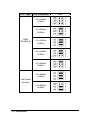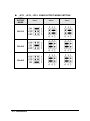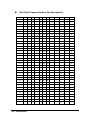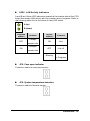
1
NuPRO -595 Series
Half Size Socket7 ISA Bus Low Power Pentium SBC
With VGA/LCD/Ethernet/WOL Interface
User’s Guide
Copyright Notice
Manual Rev 1.50: May 24, 2000
This publication is protected by copyright and all rights are reserved. No
part of it may be reproduced or transmitted by any means or in any form,
without prior consent of the original manufacturer.
The information in this document has been carefully checked and is
believed to be accurate. However, the original manufacturer assumes no
responsibility for any inaccuracies that may appear in this manual. In no
event will the original manufacturer be liable for direct, indirect, special,
exemplary, incidental, incidental or consequential damages resulting from
any defect or omission in this manual, even if advised of possibility of such
damages. The material contained herein is for informational purposes only.
Acknowledgments
Award is a registered trademark of Award Software International, Inc.
IBM and PS/2 are trademarks of International Business Machines
Corporation.
C&T is a trademark of Chips and Technologies Inc.
Intel and Pentium are registered trademarks of Intel Corporation.
Microsoft Windows is a registered trademark of Microsoft Corporation.
All other product names or trademarks are properties of their respective
owners.
Getting service from ADLINK
♦ Customer Satisfaction is always the most important thing for ADLINK
Tech Inc. If you need any help or service, please contact us and get it.
ADLINK Technology Inc.
Web Site
http://www.adlink.com.tw
Sales & Service [email protected]
NuDAQ
[email protected]
NuDAM
[email protected]
Technical
NuIPC
[email protected]
Support
NuPRO
[email protected]
Software
[email protected]
AMB
[email protected]
TEL
+886-2-82265877
FAX
+886-2-82265717
Address
9F, No. 166, Jian Yi Road, Chungho City, Taipei, 235 Taiwan, R.O.C.
♦ Please inform or FAX us of your detailed information for a prompt,
satisfactory and constant service.
Detailed Company Information
Company/Organization
Contact Person
E-mail Address
Address
Country
TEL
Web Site
FAX
Questions
Product Model
Environment to Use
Challenge Description
Suggestions for ADLink
¨OS :
¨Computer Brand :
¨M/B :
¨CPU :
¨Chipset :
¨Bios :
¨Video Card :
¨Network Interface Card :
¨Other :
NuPRO-595 Series Comparison Table
Model
NuPRO-595
NuPRO-596
Processor
Intel Pentium
Intel Pentium
AMD K6-2, K6-3
AMD K6-2, K6-3
Cyrix MII
Cyrix MII
Processor
Socket
Socket7
Socket7
Chipset
Intel 430TX
Intel 430TX
BIOS
A w ard
Award
L2 cache
512KB
512KB
Max. SDRAM
128MB
128MB
Memory
Sockets
1 x DIMM
1 x DIMM
VGA CRT/LCD
C&T 69000
C&T 69000
Watchdog
Timer
0~255 seconds or
minutes
0~255 seconds or
minutes
PC/104
Connector
NO
NO
Multi I/O Chip
Winbond83977EF
Winbond83977EF
Enhanced IDE
yes
yes
2S/1P
yes
yes
USB
yes
yes
Ethernet
(10/100Mbps)
Intel 82559
NO
H/W Monitoring Winbond W83781D Winbond W83781D
Board Size
185mm x 122mm
185mm x 122mm
Contents
Chapter 1 Introduction . . . . . . . . . . . . . . . . . . . . . . . . 1
1.1
CHECKLIST............................................................1
1.2
DESCRIPTION........................................................2
1.3
FEATURES .............................................................2
1.4
SPECIFICATIONS..................................................3
1.5
INTELLIGENCE......................................................5
Chapter 2 Installations . . . . . . . . . . . . . . . . . . . . . . . . 8
2.1
CPU INSTALLATION ............................................8
2.2
MEMORY INSTALLATION....................................9
2.3
JUMPERS ON THE NUPRO-595..........................9
2.4
CONNECTORS ON THE NUPRO-595 ...............17
2.5
WATCHDOG TIMER CONFIGURATION............30
Chapter 3 BIOS Configuration . . . . . . . . . . . . . . 3 3
3.1
BIOS INTRODUCTION ........................................34
3.2
BIOS SETUP.........................................................34
C h a p t e r 4 Intel PIIX Bus Master IDE Driver
Installation. . . . . . . . . . . . . . . . . . . . . . . . 6 1
4.1
SYSTEM REQUIREMENTS.................................61
4.2
INSTALLING THE SOFTWARE ..........................62
Chapter 5 VGA Driver Installation . . . . . . . . . 6 5
Contents • i
5.1
INSTALLING THE DRIVERS FOR WINDOWS 95
...............................................................................66
5.2
INSTALLING THE DRIVERS FOR WINDOWS 98
...............................................................................66
5.3
INSTALLING THE DRIVERS FOR WINDOWS NT
4.0..........................................................................67
Chapter 6 LAN Driver Installation Guide . 6 8
6.1
INTRODUCTION ..................................................68
6.2
FEATURES ...........................................................69
6.3
SOFTWARE DRIVERS SUPPORT ......................69
6.4
RUNNING DIAGNOSTICS ..................................69
Chapter 7 Hardware Doctor Utility . . . . . . . . 7 3
Product Warranty/Service . . . . . . . . . . . . . . . . . . . 7 9
ii • Contents
1
Introduction
This manual is designed to give you information on the NuPRO-595 CPU
board.
The topics covered in this chapter are as follows:
Ø Checklist
Ø Description
Ø Features
Ø Specifications
Ø Intelligence
Ø Layout of Key Components and Dimensions
1.1 Checklist
Please check that your package is complete and contains the items below.
If you discover damaged or missing items, please contact your dealer.
• The NuPRO-595 Industrial CPU Board
• This User’s Manual
• 1 IDE Ribbon Cable
• 1 Floppy Ribbon Connector
• 2 Serial Port Ribbon Cable and 1 Parallel Port Attached to a Mounting
Bracket
• 1 Optional 2-port
Introduction • 1
• 1 CD Containing Intel PCI IDE Driver, Flash Memory Utility, C&T 69000
VGA Driver, Intel 82559 LAN Driver and Hardware Monitor utility
1.2 Description
The NuPRO-595 is a Pentium Industrial CPU board based on the Intel
430TX chipset and is fully designed for harsh industrial environment. It
features a Socket7 processor connector that is compatible with Intel
Pentium MMX, AMD K6-2, K6-3 and Cyrix MII processors. This board
accommodates up to 128MB SDRAM configuration.
The NuPRO-595 comes with Winbond’s W83781D hardware monitoring
device that monitors system and CPU temperature, system voltages, and
CPU and chassis fan speeds to prevent system crashes by warning the
user of adverse conditions. NuPro595 also has a case-open indicator for
security.
1.3 Features
• CPU Speed 166~400MHz, Intel Pentium MMX & Low power Pentium
&AMD K6-2,K6-3 &Cyrix MII processors
• Bus Speed 66MHz
• Intel 430TX PCIset
• Up to 128MB SDRAM system memory
• C&T 69000 VGA chipset for LCD & CRT displays
• COM1 and COM2 serial ports configurable as RS232 and
RS232/422/485 respectively
• Programmable watchdog timer, 0~255 second/minutes
• High speed bi-directional SPP/ECP/EPP parallel port
• Modem ring-on
• Hardware Monitoring
• 10/100 Mbps Ethernet interface (NuPRO-595 only)
2 • Introduction
1.4 Specifications
• Processor Socket: Socket7 connector
• Processor: Intel Pentium MMX, Low Power Pentium, AMD K6-2, K6-3
166~400MHz
• Bus Speed: 66MHz
• Chipset: Intel 82430TX, 82371EB
• Secondary Cache: 512KB
• Memory Sockets:
• One 168-pin DIMM sockets
• Max. 128MB SDRAM
• Memory type: SDRAM (Synchronous DRAM)
• BIOS: Award BIOS, PnP support
• FLASH EEPROM (256KB) for BIOS update
• ISA Plug and Play (PnP) extension
• Power management
• Y2K Compliant
• DMI BIOS Support:
Desktop Management Interface (DMI) allows users to download
system hardware-level information such as CPU type, CPU speed,
internal/external frequencies and memory size.
• Super I/O: Winbond W83977EF
• Parallel Port:
• One high-speed parallel port, SPP/EPP/ECP mode
• ESD protection to 4KV
• Downstream device protection to 30V
• Serial Port:
• Two 16550 UART compatible ports with COM1 as RS232 and
COM2 as selectable RS232/422/485
• ESD protection to 2KV
Introduction • 3
• Enhanced IDE: One Enhanced IDE interfaces for up to two devices,
support PIO Mode 3/4 or Ultra DMA/33 IDE Hard Disk and ATAPI
CD-ROM.,LS120,ZIP
• FDD Interface: One floppy drives (360KB, 720KB, 1.2MB, 1.44MB,
2.88MB)
• CRT/LCD: C&T 69000 chipset
• Embedded 2MB SDRAM display memory
• Simultaneous CRT & LCD display
• LCD panel supports DSTN/TFT
• 1280x1024x8bpp colors CRT resolution
• Up to 1280x1024x8bpp colors resolution for color active matrix TFT
panels (12, 18, and 24bit analog) or (12+12), (18+18) double
pixel/CLK interface
• RAMDAC Latch-up protection
• USB Interface:
• Two USB pin-header connectors, compliant with USB Specification
Rev. 1.0
• Individual over-current protection
• DiskOnChip: The M-Systems flash disk supports syste m boot and
storage capacity from 2MB to 144MB.
• Watchdog Timer: programmable
• Program I/O port 3F0H and 3F1H to configure watchdog timer
• Time-out timing select 0~255 seconds/minutes
• Green Function: Power management via BIOS, activated through
mouse/keyboard movement
• PCI Bus Ethernet Interface: Intel 82559 chipset
• PCI local bus Ethernet controller
• IEEE 802.3 10Base-T and 100Base-TX compatible physical longer
•
•
•
•
•
support
IEEE802.3u auto-negotiation support for automatic speed selection
10/100Mbps operation in a single port PCI bus master architecture
IEEE 802.3x (100Base-TX Flow control support)
Wake on Lan support
Management communication support to reduce the total cost of
ownership (TCO)
4 • Introduction
• Keyboard and Mouse Connectors: PS/2 type mini-DIN that supports
PC/AT; supports a 5-pin external keyboard connector
• PICMG Compliance: Fully compliant to PICMG standards
• Power supply: AT or ATX
• Environmental and Mechanical:
• Power Consumption: [email protected] (max), +12V@50mA , -12V
@30mA(while K6-3/400 CPU is installed)
• Temperature: 0°C to 60°C
• Humidity: 5% to 95%
• Dimensions: 185mm x 129mm
1.5 Intelligence
• System Health Monitoring: A sensor for the CPU temperature on the
NuPRO-595 monitors the CPU te mperature, an external sensor for
system temperature, case-open indicator, fan speed detection, system
voltage monitoring
• Windows 98 shut-off: Allows shut-off control from within Windows 98
and through an ATX power supply.
• Modem ring-on: Allows system p owering on through an external
modem and through an ATX power supply.
• Year 2000 Compliant BIOS: The onboard Award BIOS is Year 2000
Compliant
• Wake On LAN: Through an ATX power supply and network connection,
systems can be turned on from the power-off state.
Introduction • 5
Figure 1 Layout of key components:
6 • Introduction
Figure 2NuPRO-595 Mechanical Drawing
Introduction • 7
2
Installations
This chapter provides information on how to use the jumpers and
connectors on the NuPRO-595 in order to set up a workable system. The
topics covered are:
Ø CPU Installation
Ø Memory Installation
Ø Jumpers on the NuPRO-595
Ø Connectors on the NuPRO-595
Ø Watchdog timer configration
2.1 CPU Installation
The NuPRO-595 Industrial CPU Board supports a Socket7 processor
socket for Intel Pentium MMX, Low power Pentium, AMD K6-2/-3 and Cyrix
MII processors.
The Socket7 connector comes with a lever to secure the processor. Before
inserting the CPU, make sure the lever is raised perpendicular to the
socket and the notch on the corner of the CPU corresponds with the notch
on the inside of the socket.
After you have installed and lock the processor into place, check if the
jumpers for the CPU type and speed are correct.
8 • Installations
Note: Ensure that the CPU heat sink and the CPU top surface are in
total contact to avoid CPU overheating problem that would
cause your system to hang or be unstable.
2.2 Memory Installation
The NuPRO-595 Industrial CPU Board supports a 168-pin DIMM sockets
for a maximum total memory of 128 SDRAMs. The memory modules can
come in sizes of 16MB, 32MB, 64MB, 128MB SDRAM.
2.3 Jumpers on the NuPRO-595
The jumpers on the NuPRO-595 allow you to configure your CPU board
according to the needs of your applications. If you have doubts about the
best jumper configuration for your needs, contact your dealer or sales
repres entative. The following table lists the jumpers and dipswitches on
NuPRO-595 and their respective functions.
JUMPER LOCATIONS ON THE NUPRO-595.................... 9
JP7: CPU CORE CLOCK MULTIPLIER........................... 11
JP1: LCD POWER SETTING........................................... 13
JP2: CLEAR CMOS CONTENT ....................................... 13
JP9: CPU CORE VOLTAGE ............................................ 14
JP4,5: CPU VIO VOLTAGE ............................................ 15
JP11,12,13: COM2 OUTPUT MODE SELECTION........... 15
Installations • 9
Figure3Jumper Locations on the NuPRO-595
u
10 • Installations
JP7: CPU Core Multiplier
The table below shows the correct setting to match the CPU frequency.
CPU Type
CPU Frequency
JP7
2 x 66MHz
133MHz
2.5x 66MHz
166MHz
Intel
Pentium
CPU
3 x 66MHz
200MHz
3.5x 66MHz
233MHz
2(6) x 66MHz
133(400)MHz
AMD
K6-2(K6-3) 2.5 x 66MHz 166MHz
3.0x 66MHz 200MHz
Installations • 11
CPU Type
CPU Frequency
3.5 x 66MHz
233MHz
4.0 x 66MHz
266MHz
AMD
K6-2(K6-3)
4.5 x 66MHz
300MHz
5.0 x 66MHz
333MHz
5.5 x 66MHz
366MHz
2.5 x 66MHz
166MHz
Low Power
Pentium
4.0 x 66MHz
266MHz
12 • Installations
JP7
CPU Type
CPU Frequency
JP7
2 x 66MHz
133MHz
2.5x 66MHz
166MHz
Cyrix MII
3 x 66MHz
200MHz
3.5x 66MHz
233MHz
u
JP1 LCD Power Setting
3.3V Setting
1
u
5V Setting
3
1
3
JP2: Clear CMOS Content
JP6
1
3
Setting
Pin 2-3
Short/Closed
1
3
Pin 1-2
Short/Closed
Function
Normal operation
Clear CMOS Content
Installations • 13
u
JP9 : CPU Core voltage
VCORE
1.9V
2.0V
2.1V
2.2V
14 • Installations
JP9
u
VCORE
JP9
2.3V
2.4V
2.8V
u
JP4 , JP5: CPU VI/O
JP4
JP5
Voltage
1
3
1
3
1
3
1
3
2.5V
3.3V
Installations • 15
u
JP11 , JP12 , JP13: COM2 OUTPUT MODE SETTING
COM2
OUTPUT
MODE
RS-232
RS-422
RS-485
16 • Installations
JP11
JP12
JP13
2.4 Connectors on the NuPRO-595
The connectors on the NuPRO-595 allow you to connect external devices
such as keyboard, floppy disk drives, hard disk drives, printers, etc. The
following tables list the connectors on NuPRO-595 and their respective
functions.
CONNECTORS ON THE NUPRO-595 ............................. 16
CN4: MISCELLANEOUS CONNECTOR........................... 18
CN1: EXTERNAL KEYBOARD CONNECTOR.................. 20
IDE1: EIDE CONNECTORS............................................. 20
CN3: FLOPPY DRIVE CONNECTOR ............................... 21
CN5: FLAT PANEL LCD CONNECTOR ........................... 22
FLAT PANEL DISPLAY INTERFACE PIN DESCRIPTIONS
....................................................................................... 23
CN2: PARALLEL PORT CONNECTOR ............................ 24
CN11: COM1 SERIAL PORT ........................................... 25
CN10: COM2 SERIAL PORT ........................................... 25
CN9: PS/2 KEYBOARD CONNECTOR ............................ 26
CN8: PS/2 MOUSE CONNECTOR ................................... 26
CN6: VGA CRT CONNECTOR ........................................ 26
CN7: RJ45 CONNECTOR ............................................... 27
FN1: CPU FAN POWER CONNECTOR............................ 27
CN12: USB CONNECTORS ............................................ 27
CN13: POWER CONNECTOR………………………………….. 27
LED1: LAN ACTIVITY INDICATORS LED....................... 28
JP8: CASE OPEN INDICATOR ....................................... 28
JP6: SYSTEM TEMPERATURE DETECTION.................. 28
Installations • 17
Figure 4Connector Locations on the NuPRO-595
18 • Installations
u
CN4: Miscellaneous Connector
The Miscellaneous connector is a 20-pin header that provides interfaces
for the following functions.
1
11
Power LED
PC Speaker
Keylock
Reset Switch
Hard Disk LED
ATX Power Input
ATX Power On Switch
10
20
l Speaker: Pins 11 - 14
This connector provides an interface to a speaker for audio tone
generation. An 8-ohm speaker is recommended.
11
14
Pin #
11
12
13
14
Signal Name
Speaker out
No connect
No connect
+5V
l Power LED and Keylock: Pins 11 - 15
The power LED indicates the status of the main power switch. The keylock
switch, when closed, will disable the keyboard function.
1
4
Pin #
1
2
3
4
5
Signal Name
+5V
No connect
Power LED#
Keylock#
Ground
Installations • 19
l ATX Power ON Switch: Pins19 and 20
This 2-pin connector is an “ATX Power Supply On/Off Switch” on the
system that connects to the power switch on the case. When pressed, the
power switch will force the system to power on. When pressed again, it will
force the system to power off.
19 20
l Reset Switch: Pins 15 and 16
The reset switch allows the user to reset the system without turning the
main power switch off and then on again. Orientation is not required when
making a connection to this header.
15 16
l Hard Disk LED Connector: Pins 17 and 18
This connector connects to the hard drive activity LED on control panel.
This LED will flash when the HDD is being accessed.
17 18
Pin #
17
18
Signal Name
HDD LED#
+5V
l ATX Power Input: Pins 6 -10
The power LED indicates the status of the main power switch. The keylock
switch, when closed, will disable the keyboard function.
56
20 • Installations
10
Pin #
6
7
8
9
10
Signal Name
Ground
No connect
Poweron#
+5VSB
+5VSB
u
CN1: External Keyboard Connector
1
u
Pin #
1
2
3
4
5
Signal Name
Keyboard clock
Keyboard data
NC
GND
Vcc
IDE1: EIDE Connectors
IDE1: Primary IDE Connector
Signal Name
Pin #
Reset IDE
1
Host data 7
3
Host data 6
5
Host data 5
7
Host data 4
9
Host data 3
11
Host data 2
13
Host data 1
15
Host data 0
17
Ground
19
DRQ0
21
Host IOW
23
Host IOR
25
IOCHRDY
27
DACK0
29
IRQ14
31
Address 1
33
Address 0
35
Chip select 0
37
Activity
39
Pin #
2
4
6
8
10
12
14
16
18
20
22
24
26
28
30
32
34
36
38
40
Signal Name
Ground
Host data 8
Host data 9
Host data 10
Host data 11
Host data 12
Host data 13
Host data 14
Host data 15
Ground
Ground
Ground
Host ALE
Ground
No connect
No connect
Address 2
Chip select 1
Ground
Installations • 21
u
CN3: Floppy Drive Connector
CN3 is a 34-pin header and will support up to 2.88MB floppy drives.
Signal Name Pin # Pin #
Signal Name
Drive density
Ground
1
2
selection
Ground
3
4
No connect
Drive density
Ground
5
6
selection
Ground
7
8
Index
Ground
9
10
Motor enable 0
Ground
11
12
Drive select 1
Ground
13
14
Drive select 0
Ground
15
16
Motor enable 1
Ground
17
18
Direction
Ground
19
20
Step
Ground
21
22
Write data
Ground
23
24
Write gate
Ground
25
26
Track 00
Ground
27
28
Write protect
Ground
29
30
Read data
Ground
31
32
Side 1 select
Ground
33
34
Diskette change
22 • Installations
u
CN5: Flat Panel LCD Connector
CN5 is a 50-pin (dual in line header) for flat panel LCD displays. The
following shows th e pin assignments of this connector.
Signal Name
VCLK
Pin #
1
Pin #
2
Signal Name
P33
P34
3
4
P31
P35
5
6
P32
P30
7
8
P28
P29
9
10
P27
P25
11
12
P26
P24
13
14
P21
P23
15
16
P22
P16
17
18
P20
P17
19
20
P18
P19
21
22
P14
P13
23
24
P12
P15
25
26
P11
P7
27
28
PD10
5V 0R 3.3V
P9
29
31
30
32
5V 0R 3.3V
P8
P4
33
34
P6
P3
35
36
P5
P2
37
38
P1
MDE
39
40
P0
SHFCLK
41
42
ENABKL
FPVDD
43
44
FLM(V SYNC)
FPVEE
45
46
LP(H SYNC)
GND
47
48
GND
+12V
49
50
+12V
Installations • 23
u
Flat Panel Display Interface Pin Descriptions
Mono Mono Mono
DD
Color
Color Color Color
TFT
TFT
SS
DD
TFT
TFT
Pin Name
8-bit
8-bit
P0
D0
UD3
16-bit 9/12/16 18/24 36-bit 18/24
bit
bit
bit
UD7
B0
B0
FB0 FB0
P1
D1
UD2
UD6
B1
B1
FB1
P2
D2
UD1
UD5
B2
B2
P3
D3
UD0
UD4
B3
P4
D4
LD3
UD3
P5
D5
LD2
P6
D6
P7
D7
Color
Color
Color
Color
Color
TFT+HR STN-SS STN-SS STN-DD STN-DD
8-bit
(4bP)
R1
16-bit
(4bP)
R1
8-bit
(4bP)
UR1
16-bit
(4bP)
UR0
24-bit
FB1
B1
G1
UG1
UG0
UG0
FB2
FB2
G2
B1
UB1
UB0
UB0
B3
FB3
FB3
B3
R2
UB2
UR1
LR0
B4
B4
FB4
SB0
G4
G3
LR1
LR0
LG0
UD2
G0
B5
FB5
SB1
R5
B2
LG1
LG0
LB0
LD1
UD1
G1
B6
SB0
SB2
B5
R3
LB1
LB0
UR1
LD0
LR2
UR0
UD0
G2
B7
SB1
B3
G3
LR1
UG1
P8
LD7
G3
G0
SB2
FG0
B3
UG1
UB1
P9
LD6
G4
G1
SB3
FG1
R4
UB1
LR1
P10
LD5
G5
G2
SB4
FG2
G4
UR2
LG1
P11
LD4
R0
G3
SB5
FG3
B4
UG2
LB1
P12
LD3
R1
G4
FG0
SG0
R5
LG1
UR2
P13
LD2
R2
G5
FG1
SG1
G5
LB1
UG2
P14
LD1
R3
G6
FG2
SG2
B5
LR2
UB2
P15
LD0
R4
G7
FG3
SG3
G6
LG2
LR2
P16
R0
FG4
FR0
P17
R1
FG5
FR1
LB2
P18
R2
SG0
FR2
UR3
P19
R3
SG1
FR3
UG3
P20
R4
SG2
SR0
LR3
P21
R5
SG3
SR1
LG3
P22
R6
SG4
SR2
LB3
P23
R7
SG5
SR3
P24
FR0
P25
FR1
P26
FR2
P27
FR3
P28
FR4
P29
FR5
P30
SR0
P31
SR1
P32
SR2
24 • Installations
LG2
P33
SR3
P34
SR4
P35
SHFCLK
Pixels/Clk:
u
SR5
SHFCLK SHFCLK SHFCLK SHFCLK SHFCLK SHFCLK SHFCLK
8
8
16
1
1
2
2
SHFCLK
SHFCLK
SHFCLK
SHFCLK
SHFCLK
2-2/3
5-1/3
2-2/3
5-1/3
8
CN2: Parallel Port Connector
The following table describes the pin out assignments of this connector.
Signal Name
Line printer strobe
PD0, parallel data 0
PD1, parallel data 1
PD2, parallel data 2
PD3, parallel data 3
PD4, parallel data 4
PD5, parallel data 5
PD6, parallel data 6
PD7, parallel data 7
ACK, acknowledge
Busy
Paper empty
Select
Pin #
1
2
3
4
5
6
7
8
9
10
11
12
13
Pin #
14
15
16
17
18
19
20
21
22
23
24
25
N/A
Signal Name
AutoFeed
Error
Initialize
Select
Ground
Ground
Ground
Ground
Ground
Ground
Ground
Ground
N/A
Installations • 25
u
CN11: COM1 Serial Port
CN11, a 10-pin header connector, is an onboard serial port of h
te
NuPRO-590. The following table shows the pin assignments of this
connector.
Pin #
1
2
3
4
5
6
7
8
9
10
u
Signal Name
DCD, Data carrier detect
RXD, Receive data
TXD, Transmit data
DTR, Data terminal ready
GND, ground
DSR, Data set ready
RTS, Request to send
CTS, Clear to send
RI, Ring indicator
NC
CN10: COM2 Serial Port
CN10, a 10-pin header connector, is the onboard COM2 serial port of the
NuPRO-595. The following table shows its pin assignments.
Pin #
1
2
3
4
5
6
7
8
9
10
26 • Installations
RS-232
DCD
RX
TX
DTR
GND
DSR
RTS
CTS
RI
NC
Signal Name
R2-422
TXTX+
RX+
RXGND
RTSRTS+
CTS+
CTSNC
RS-485
DATADATA+
NC
NC
GND
NC
NC
NC
NC
NC
u
CN9: PS/2 Keyboard Connector
Pin #
1
2
3
4
5
6
u
Signal Name
Keyboard data
N.C.
GND
5V
Keyboard clock
N.C.
CN8: PS/2 Mouse Connector
Pin #
1
2
3
4
5
6
u
Signal Name
Mouse data
N.C.
N.C.
5V
Mouse Clock
N.C.
CN6: VGA CRT Connector
The pin assignments of the CN6 VGA CRT connector are as follows:
Signal
Name
Red
Blue
GND
GND
N.C.
N.C.
HSYNC
NC
Pin
Pin
Signal Name
1
3
5
7
9
11
13
15
2
4
6
8
10
12
14
Green
N.C.
GND
GND
GND
N.C.
VSYNC
Installations • 27
u
CN7: RJ45 Connector
This connector is for the 10/100Mbps Ethernet capability of the CPU board.
The figure below shows the pin out assignments of this connector and its
corresponding input jack.
TD+(pin#1)
T D-(pin#2)
RD+(pin#3)
RD-(pin#6)
u
FN1: CPU Fan Power Connector
FN1 is a 3-pin header for the CPU fan. The fan must be a 12V fan.
1
u
2
3
Pin #
1
2
Signal Name
Rotation
+12V
3
Ground
CN12: USB Connectors
The following table shows the pin outs of the USB connectors.
2
u
8
Pin #
1
3
5
7
Pin #
2
4
6
8
Signal Name
Vcc
USB0-,USB1USB0+, USB1+
Ground
CN13: Power Connectors
CN13 is a 4 -pin header for power input connector
Pin #
1
2
3
4
28 • Installations
Signal Name
+12V
Ground
Ground
+5V
u
LED1: LAN Activity Indicators
A and B are Green LED indicators located at the bracket side of the CPU
board that shows LAN activity and the transfer rate in progress. Refer to
the following table for the functions of each LED status.
A (up)
B (down)
A(Speed
status)
OFF
Function
10Mbps
B(Link
status)
Function
ON
Link
OFF
Link off
transfer rate
100Mbps
ON
transfer rate
Data transfer
Blinking
in Progress
u
JP8: Case open indicator
Connect a cable to case open sensor
u
JP6: System temperature detection
Connect a cable to thermal sensor
Installations • 29
2.5 Watchdog Timer Configuration
The function of the watchdog timer is to reset the system automatically. It
contains a one-second/minute resolution down counter, CRF2 of logical
device 8, and two Watchdog control registers, WDT_CTRL0 and
WDT_CTRL1 of logical device 8. We can uses compatible PNP protocol to
access configuration registers for setting up watchdog timer configuration.
To grogram configuration registers, the following configuration sequence
must be followed:
(1) Enter the extended function mode by writing 87h to the location
3F0h twice.
(2) Configure the configuration registers
(3) Exit the extended function mode by writing 0AAh to the location
3F0h.
The following example is written in Intel 8086 assembly language. It will
reset the system in 15 seconds. We can use both keyboard interrupt and
mouse interrupt to cause the watchdog to reload and start to count down
from the value of CRF2.
MODEL SMALL
DATA
CODE
STARTUP
BEGIN:
;----------------------------------------------------------------------;Enter the extended function mode, interruptible double-write
;----------------------------------------------------------------------MOV DX,3F0H
MOV AL,87H
OUT DX,AL
OUT DX,AL
;---------------------------------------------------------------------;Configurate logical device 7, configuration register CRE2
;---------------------------------------------------------------------MOV DX,3F0H
MOV AL,07H
OUT DX,AL ;point to logical Device Number Reg.
MOV DX,3F1H
MOV AL,07H ;select device 7
30 • Installations
OUT DX,AL
MOV
MOV
OUT
MOV
MOV
OUT
DX,3F0H
AL,0E2H ;device 7, CRE2
DX,AL
DX,3F1H
AL,0AH ;Watch Dog Timer Output
DX,AL
MOV
MOV
OUT
MOV
MOV
OUT
DX,3F0H
AL,2AH ;CR2A
DX,AL
DX,3F1H
AL,80H ;bit7=0 -> KBRST, bit7=1 -> GP12
DX,AL
MOV
MOV
OUT
MOV
MOV
OUT
DX,3F0H
AL,07H
DX,AL
DX,3F1H
AL,08H ;select device 8
DX,AL
MOV
MOV
OUT
MOV
MOV
OUT
DX,3F0H
AL,0F3H ;device 8, CRF3
DX,AL
DX,3F1H
AL,06H ;Watch Dog Timer is reset upon a
DX,AL ;Mouse & Keyboard interrupt
MOV
MOV
OUT
MOV
MOV
OUT
DX,3F0H
AL,07H
DX,AL
DX,3F1H
AL,08H
DX,AL
MOV
MOV
OUT
MOV
MOV
OUT
DX,3F0H
AL,0F4H ;CRF4
DX,AL
DX,3F1H
AL,40H ;bit6 =1 -> counter counts in seconds
DX,AL ;bit6 =0 -> counter counts in minutes
Installations • 31
MOV
MOV
OUT
MOV
MOV
OUT
DX,3F0H
AL,07H
DX,AL
DX,3F1H
AL,08H
DX,AL
MOV DX,3F0H
MOV AL,0F2H ;CRF2
OUT DX,AL
MOV DX,3F1H
MOV AL,0FH ;Time-out occurs after the value of CRF2
OUT DX,AL ;range 1~255, 00 -> disable Time-out
;----------------------------------;Exit extended function mode
;----------------------------------MOV DX,3F0H
MOV AL,0AAH
OUT DX,AL
EXIT
END
32 • Installations
3
BIOS Configuration
This chapter describes the different settings available in the Award BIOS.
The topics covered in this chapter are as follows:
BIOS INTRODUCTION ................................................... 33
BIOS SETUP .................................................................. 33
STANDARD CMOS SETUP............................................. 34
BIOS FEATURES SETUP ............................................... 38
CHIPSET FEATURES SETUP......................................... 43
POWER MANAGEMENT SETUP..................................... 46
PNP/PCI CONFIGURATION............................................ 52
LOAD BIOS DEFAULTS.................................................. 53
LOAD SETUP DEFAULTS............................................... 54
INTEGRATED PERIPHERALS ........................................ 54
SUPERVISOR / USER PASSWORD................................. 57
IDE HDD AUTO DETECTION.......................................... 58
SAVE & EXIT SETUP..................................................... 59
EXIT WITHOUT SAVING................................................ 59
BIOS Configuration • 33
3.1 BIOS Introduction
The Award BIOS (Basic Input/Output Subroutine) installed in your
computer system’s ROM supports Intel Pentium & AMD K6-2/3
processors. The BIOS provides critical low-level support for standard
devices such as disk drives, serial ports, and parallel ports. It also adds
virus and password protection as well as special support for detailed
fine-tuning of the chipset controlling the entire system.
3.2 BIOS Setup
The Award BIOS provides a Setup utility program for specifying the system
configurations and settings. The BIOS ROM of the system stores the Setup
utility. When you turn on the computer, the Award BIOS is immediately
activated. Pressing the <Del> key immediately allows you to enter the
Setup utility. If you are a little bit late pressing the <Del> key, POST (Power
On Self Test) will continue with its test routines, thus preventing you from
invoking the Setup. If you still wish to enter Setup, restart the system by
pressing the “Rest” button or simultaneously pressing the <Ctrl>, <Alt> and
<Delete> keys. You can also restart by turning the system Off and back On
again. The following message will appear on the screen:
Press
<DEL>
to
Enter
Setup
In general, you press the arrow keys to highlight items, <Enter> to select,
the <PgUp> and <PgDn> keys to change entries, <F1> for help and <Esc>
to quit. When you enter the Setup utility, the Main Menu screen will appear
on the screen. The Main Menu allows you to select from various setup
functions and exit choices.
ROM PCI/ISA BIOS
CMOS SETUP UTILITY
AWARD SOFTWARE, INC.
STANDARD CMOS SETUP
INTEGRATED PERIPHERALS
BIOS FEATURES SETUP
SUPERVISOR PASSWORD
CHIPSET FEATURES SETUP
USER PASSWORD
POWER MANAGEMENT SETUP
IDE HDD AUTO DETECTION
PNP/PCI CONFIGURATION
SAVE & EXIT SETUP
LOAD BIOS DEFAULTS
EXIT WITHOUT SAVING
LOAD SETUP DEFAULTS
ESC : Quit
á â à ß : Select Item
F10 : Save & Exit Setup
(Shift) F2 : Change Color
Time, Date, Hard Disk Type
34 • BIOS Configuration
The section below the setup items of the Main Menu displays the control
keys for this menu. Another section at the bottom of the Main Menu just
below the control keys section displays information on the currently
highlighted item in the list.
Note: After making and saving system changes with Setup, you find
that your computer cannot boot, the Award BIOS supports an
override to the CMOS settings that resets your system to its
default.
We strongly recommend that you avoid making any changes to
the chipset defaults. These defaults have been carefully chosen
by both Award and your system manufacturer to provide the
absolute maximum performance and reliability.
u
Standard CMOS Setup
“Standard CMOS Setup” choice allows you to record some basic hardware
configurations in your computer system and set the system clock and error
handling. If the motherboard is already installed in a working system, you
will not need to select this option. You will need to run the Standard CMOS
option, however, if you change your system hardware configurations, the
onboard battery fails, or the configuration stored in the CMOS memory was
lost or damaged.
ROM PCI/ISA BIOS
STANDARD CMOS SETUP
AWARD SOFTWARE, INC.
Date (mm:dd:yy) : Wed, Oct 6 1999
Time (hh:mm:ss) : 00 : 00 : 00
CYLS HEADS PRECOMP
Master IDE
Slave IDE
( 0MB)
( 0MB)
0
0
0
0
Drive A
Drive B
: 1.44M, 3.5in
: None
LCD&CRT
Halt On
ESC : Quit
F1 : Help
: Both
: All Errors
á â à ß : Select
Item
(Shift) F2 : Change Color
0
0
LANDZ
SECTOR
MODE
0
0
0
0
Auto
Auto
Base Memory
Extended
Memory
Other Memory
:
:
640K
15360K
:
384K
Total Memory
:
16384K
PU / PD / + / - : Modify
BIOS Configuration • 35
At the bottom of the menu are the control keys for use on this menu. If you
need any help in each item field, you can press the <F1> key. It will display
the relevant information to help you. The memory display at the lower
right-hand side of the menu is read-only. It will adjust automatically
according to the memory changed. The following describes each item of
this menu.
Date
The date format is:
Day
Month
Date
Year
Sun to Sat (read only)
1 to 12
1 to 31
1994 to 2079
To set the date, highlight the “Date” field and use the PageUp/ PageDown
or +/- keys to set the current time.
Time
The time format is:
Hour
Minute
Second
00 to 23
00 to 59
00 to 59
To set the time, highlight the “Time” field and use the <PgUp>/ <PgDn> or
+/- keys to set the current time.
Primary HDDs / Secondary HDDs
The onboard PCI IDE connectors provide Primary and Secondary
channels for connecting up to four IDE hard disks or other IDE devices.
Each channel can s upport up to two hard disks; the first is the “Master” and
the second is the “Slave”.
To enter the specifications for a hard disk drive, you must select a “Type”.
There are 45 predefined types and 4 user definable types are for
Enhanced IDE BIOS. Type 1 o
t 45 are predefined. [Type “User” is
user-definable. For the Primary Master/Slave as well as Secondary
Master/Slave, you can select “Auto” under the TYPE and MODE fields.
This will enable auto detection of your IDE drives and CD-ROM drive
during POST.]
36 • BIOS Configuration
Press <PgUp>/<PgDn> to select a numbered hard disk type or type the
number and press the <Enter> key. The hard disk will not work properly if
you enter incorrect information for this field. If your hard disk drive type is
not matched or listed, you can use Type User to define your own drive type
manually. If you select Type User, related information is asked to be
entered to the following items.
CYLS.
Number of cylinders
HEADS
Number of read/write heads
PRECOMP
Write precompensation
LANDZONE Landing zone
SECTORS
Number of sectors
The SIZE item automatically adjust according to the configuration.
MODE (for IDE HDD only) :
Auto
<Default>
Normal
Large
LBA
Auto-detect the HDD mode
HD < 528MB
For MS-DOS only
HD > 528MB and supports Logical Block Addressing
Note: The specifications of your drive must match with the drive table.
The hard disk will not work properly if you enter incorrect
information in these fields. If your hard disk drive type is not
matched or listed, you can use Type User to define your own
drive type manually.
Drive A / Drive B
These fields identify the types of floppy disk drive A or drive B that has
been installed in the computer. The available specifications are:
None
360KB 5.25 in.
1.2MB 5.25 in.
720KB 3.5 in.
1.44MB 3.5 in.
<Default>
2.88MB 3.5 in.
No floppy drive be installed
5.25 inch floppy drive, 360KB capacity
5.25 in. floppy drive, 1.2MB capacity
3.5 in. floppy drive, 720KB capacity
3.5 in. floppy drive, 1.44MB capacity
3.5 in. floppy drive, 2.88MB capacity
BIOS Configuration • 37
LCD&CRT
The NuPRO-590 CPU board can supports two display interfaces, Panel
and CRT, concurrently. This field selects the interface of video display. You
can choose the following display interface:
Auto
Both
CRT <Default>
LCD
Auto-detect the display interface installed in
your system
Both CRT & LCD are display interface
Use CRT monitor as display interface
Use LCD Panel as display interface
If you install an LCD panel on the NuPRO-595 CPU board, you can also
select the panel type in the “POWER MANAGEMENT SETUP” section.
Halt On
This field determines whether the system will halt if an error is detected
during power up.
The system boot will not be halted for any
error that may be detected.
All Errors
Whenever the BIOS detects a non-fatal error,
<Default>
the system will stop and you will be prompted.
All, But Keyboard The system boot will not be halted for a
keyboard error; it will stop for all other errors
All, But Diskette The system boot will not be halted for a disk
error; it will stop for all other errors.
All, But Disk/Key The system boot will not be halted for a
keyboard or disk error; it will stop for all others.
No Errors
38 • BIOS Configuration
u
BIOS Features Setup
This section allows you to configure and improve your system and allows
you to set up some system features according to your preference.
ROM / PCI ISA BIOS
BIOS FEATURES SETUP
AWARD SOFTWARE, INC.
Virus Warning
CPU Internal Cache
External Cache
Quick Power On Self Test
Boot From LAN First
Boot Sequence
Swap Floppy Drive
Boot Up Floppy Seek
Boot Up Numlock Status
Boot Up System Speed
Gate A20 Option
Typematic Rate Setting
Typematic Rate (chars/Sec)
Typematic Delay (Msec)
Security Option
: Disabled
: Enabled
: Enabled
: Enabled
: Disabled
: A, C, SCSI
: Disabled
: Enabled
: On
: Low
: Fast
: Disabled
:6
: 250
: Setup
Video BIOS Shadow
C8000-CBFFF Shadow
CC000-CFFFF Shadow
D0000-D3FFF Shadow
D4000-D7FFF Shadow
D8000-DBFFF Shadow
DC000-DFFF Shadow
: Enabled
: Disabled
: Disabled
: Disabled
: Disabled
: Disabled
: Disabled
PCI /VGA Palette Snoop
OS Select For DRAM>64MB
: Disabled
: Non-OS2
ESC : Quit
á â à ß : Select Item
F1 : Help
PU/PD/+/- : Modify
F5 : Old Values
(Shift) F2 : Color
F6 : Load BIOS Defaults
F7 : Load Setup Defaults
Virus Warning
Enabled
This item protects the boot sector and partition table
of your hard disk against accidental modifications. If
an attempt is made, the BIOS will halt the system and
display a warning message. If this occurs, you can
either allow the operation to continue or run an
anti-virus program to locate and remove the problem.
Disabled No warning message appears
<Default>
Note: Many disk diagnostic programs, which attempt to access the
boot sector table, can cause the virus warning. If you will run
such a program, disable the Virus Warning feature.
BIOS Configuration • 39
CPU Internal Cache / External Cache
Cache memory is additional memory that is much faster than conventional
DRAM (system memory). CPUs from 486-type on contain internal cache
memory, and most, but not all, modern PCs have additional (external)
cache memory. When the CPU requests data, the system transfers the
requested data from the main DRAM into cache memory, for even faster
access by the CPU. These items allow you to enable (speed up memory
access) or disable the cache function.
Enabled
Open CPU Internal Cache / External Cache
<Default>
Disabled Close CPU Internal Cache / External Cache
Quick Power On Self Test
When enabled, this field speeds up the Power On Self Test (POST) after
the system is turned on. If it is set to Enabled, BIOS will skip some items.
Enabled
Enable quick POST
<Default>
Disabled Normal POST
Boot From LAN First
This field allows you to use a bootable LAN device to boot the system first.
Enabled
Boot the system from LAN first
Disabled Boot from the device on the system
<Default>
Boot Sequence
This field determines the drive that the system searches first for an
operating system. The options are :
A, C, SCSI
<Default>
C, A, SCSI
C, CDROM, A
CDROM, C, A
40 • BIOS Configuration
D, A, SCSI
SCSI, C, A
SCSI, A, C
C only
ZIP100, C
LS120,C
Swap Floppy Drive
This item allows you to determine whether to enable Swap Floppy Drive or
not.
Enabled
The BIOS swaps floppy drive assignments so that
Drive A becomes Drive B, and Drive B becomes
Drive A.
Disabled Disable the BIOS to swap floppy drive
<Default>
Boot Up Floppy Seek
Enabled The BIOS will seek whether or not the floppy drive
<Default> installed has 40 or 80 tracks. 360K type has 40 tracks
while 760K, 1.2M and 1.44M all have 80 tracks
Disabled BIOS will not search the type of floppy disk drive by
track number
Boot Up NumLock Status
On
Keypad is number keys
<Default>
Off
Keypad is arrow keys
Boot Up System Speed
High
Set the speed to high
<Default>
Low
Set the speed to low
Gate A20 Option
This field allows you to select how Gate A20 is worked. Gate A20 is a
device used to address memory above 1 MB.
Fast
The A20 signal controlled by chipset specific method
<Default>
Normal The A20 signal controlled by keyboard controller or
chipset hardware
BIOS Configuration • 41
Typematic Rate Setting
Enabled Enable typematic rate and typematic delay
programming
Disable typematic rate and typematic delay
Disabled programming. The system BIOS will use default
<Default> value of these 2 items And the default controlled by
keyboard
Typematic Rate (Chars/Sec)
When the typematic rate is enabled, the system registers repeated
keystrokes speeds. You can select speed range from 6 to 30 characters
per second. By default, this item is set to 6.
Typematic Delay (Msec)
When the typematic rate is enabled, this item allows you to set the time
interval for displaying the firs t and second characters. By default, this item
is set to 250msec.
Security Option
This field allows you to limit access to the System and Setup.
The system always boots up and prompts for the
Setup
<Default> Supervisor Password only when the Setup utility is
called up
System The system prompts for the User Password every
time you boot up
Note: To disable security, select PASSWORD SETTING at Main Menu
and then you will be asked to enter the password. If you do not
type anything and just press <Enter> key, it will disable security,
Once the security is disabled, you can boot up the system and
access to Setup freely.
42 • BIOS Configuration
PCI/VGA Palette Snoop
Some non-standard VGA display boards may not show colors properly.
This field allows you to set whether MPEG ISA/VESA VGA Boards can
work with PCI/VGA or not.
Enabled PCI/VGA can work with MPEG ISA/VESA VGA board
Disabled PCI/VGA can not work with MPEG ISA/VESA VGA
<Default> board
OS Select for DRAM > 64MB
This option allows the system to access greater than 64MB of DRAM
memory when used with OS/2 that depends on certain BIOS calls to
access memory. The default setting is Non-OS/2.
Video BIOS Shadow
This item allows you to change the Video BIOS location from ROM to RAM.
Video Shadow will increase the video speed.
Enabled Video shadow is enabled
<Default>
Disabled Video shadow is disabled
C8000 - CBFFF Shadow/DC000 - DFFFF Shadow
Shadowing a ROM reduces the memory available between 640KB to
1024KB. These fields determine whether optional ROM will be copied to
RAM or not.
Enabled Optional shadow is enabled
Disabled Optional shadow is disabled
<Default>
BIOS Configuration • 43
u
Chipset Features Setup
This Setup menu controls the configuration of the chipset.
ROM PCI/ISA BIOS
CHIPSET FEATURES SETUP
AWARD SOFTWARE INC.
*Auto Configuration
*DRAM Leadoff Timing
*DRAM Read Burst (EDO/FP)
*DRAM Write Burst Timing
*Fast EDO Lead Off
*Refresh RAS# Assertion
*Fast RAS To CAS Delay
*DRAM Page Idle Timer
*DRAM Enhanced Paging
*Fast MA to RAS# Delay
*SDRAM(CAS Lat/RAS-to-CAS)
*SDRAM Speculative Read
System BIOS Cacheable
Video BIOS Cacheable
8 Bit I/O Recovery Time
16 Bit I/O Recovery Time
Memory Hole At 15M-16M
:
:
:
:
:
:
:
:
:
:
:
:
:
:
:
:
:
:
Disabled
Auto Detect DIMM/PCI Clk
: Enabled
11/7/3
X444/x444
X444
Disabled
5 Clks
3
2 Clks
Enabled
2 Clks
2/2
Disabled
Disabled
Disabled
NA
NA
Disabled
Power-Supply Type
Spread Spectrum
Case Open_Warning
CPU Warning Temperature
Current System Temp.
Current CPU1 Temperature
Current CPUFAN1 Speed
VCORE
:
3.3 V
:
+5V
+12V
:
- 12 V
: AT
: Disabled
: Enabled
: Disabled
: 60°C/140°F
:
:
:
:-
ESC : Quit
á â à ß : Select Item
F1 : Help
PU/PD/+/- : Modify
F5 : Old Values
(Shift) F2 : Color
F6 : Load BIOS Defaults
F7 : Load Setup Defaults
Note: The items that be marked in this menu are show-only. The
system manufacturer for high performance configures the item
value.
System BIOS Cacheable
When this function is enabled, the BIOS ROM’s addresses at
F0000H-FFFFFH will be duplicated into the SRAM. It will work with the
cache controller that is enabled.
Enabled BIOS access cached
<Default>
Disabled BIOS access not cached
Video BIOS Cacheable
As with caching the system BIOS above, enabling the Video BIOS cache
will cause access to video BIOS addressed at C0000H to C7FFFH to be
cached, it the cache controller is also enabled.
Enabled
Video BIOS access cached
<Default>
Disabled Video BIOS access not cached
44 • BIOS Configuration
8 Bit I/O Recovery Time
The recovery time is the length of time, which the system delays after the
completion of an input/output request. The CPU clocks measure it. This
delay takes place because the CPU is operating much faster than the
input/output bus that the CPU must be delayed to allow for the completion
of the I/O.
This option specifies the length of the delay (in sysclks) inserted between
consecutive 8-bit I/O operations. The settings are 1, 2, 3, 4, 5, 6, 7, or 8.
The default setting is NA.
16 Bit I/O Recovery Time
This option specifies the length of the delay (in sysclks) inserted between
consecutive 16-bit I/O operations. The settings are 1, 2, 3, 4.The default
setting is NA.
Memory Hole at 15MB - 16MB
In order to improve performance, certain space in memory can be reserved
for ISA boards. This field allows you to reserve 15MB to 16MB memory
address space to ISA expansion boards. This makes memory from 15MB
and up unavailable to the system. Expansion boards can only access
memory up to 16MB. By default, this field is set to Disabled.
Auto Detect DIMM/PCI Clk
When enabled, the system automatically shuts off clocks of unused
DIMM/PCI slots. The default setting is Disabled.
Power-Supply Type
AT<Default>
ATX
This power supply is reserved for traditional
system that uses the AT power supply.
The ATX power supply is used for more
functions about the system’s power
management. Some wake up event function is
provided by this type power supply.
BIOS Configuration • 45
Spread Spectrum
This field sets the value of the spread spectrum. Options are Disabled,
1.8% (CNTR), 0.6% (CNTR), 1.8% (DOWN), and 0.6% (DOWN). The
default setting is Disabled. This field is for CE testing use only.
Case_Open Warning
When the system is power on, to open the system’s case may causes
accidental damage. If this field enabled, it alarms by speaker beeping. You
must turn off the power and close the system’s case to disable the beeping.
The default setting is Disabled.
CPU Warning Temperature
This field sets the threshold temperature at which an alert is sounded
through the system’s speaker. The CPU temperature is monitored by the
onboard thermal sensor to prevent the CPU from overheating.
Current System/CPU Temperature
These read-only fields reflect the functions of the hardware thermal sensor
that monitors the CPU and system temperatures to ensure the system is
stable.
Current CPU Fan Speed
These read-only fields show the current speeds in RPM (revolution per
minute) for the CPU fan and chassis fan as monitored by the hardware
monitoring IC.
VCORE/3.3V/+12V/-12V/+5V
These read-only fields show the current voltages in the voltage regulators
and power supply as monitored by the hardware monitoring IC.
Shutdown Temperature
This field allows you to set the temperature at which the system
automatically shuts down once it is reached, in order to avoid damage to
system components.
46 • BIOS Configuration
u
Power Management Setup
The Power Management Setup allows you to save energy of your system
effectively. It will shut down the hard disk and turn off video display after a
period of inactivity.
ROM PCI/ISA BIOS
POWER MANAGEMENT SETUP
AWARD SOFTWARE, INC.
ACPI Function
Power Management
PM Control by APM
Video Off Method
Video Off After
Modem Use IRQ
Doze Mode
Standby Mode
Suspend Mode
HDD Power Down
Throttle Duty Cycle
ZZ Active in Suspend
PCI/VGA Active Monitor
Soft-Off by PWR-BTTN
CPUFAN Off In Suspend
PowerOn by Ring
Wake Up On LAN
IRQ 8 Break Suspend
: Enabled
: User Define
: Yes
: V/H SYNC +Blank
: Standby
:3
: Disabled
: Disabled
: Disabled
: Disabled
: 62.5%
: Disabled
: Disabled
: Instant-Off
: Disabled
: Disabled
: Disabled
: Disabled
** Reload Global Timer Events **
IRQ3 (3-7, 9-15), NMI
: Disabled
Primary IDE 0
: Enabled
Primary IDE 1
: Enabled
Secondary IDE 0
: Disabled
Secondary IDE 1
: Disabled
Floppy Disk
: Disabled
Serial Port
: Enabled
Parallel Port
: Disabled
Panel Type Selectable
: PANEL-5
ESC : Quit
á â à ß : Select Item
F1 : Help
PU/PD/+/- : Modify
F5 : Old Values
(Shift) F2 : Color
F6 : Load BIOS Defaults
F7 : Load Setup Defaults
ACPI function
ACPI stands for Advanced Configuration Power Interface. The default
setting of this field Disabled.
Power Management
This field allows you to select the type of power saving management
modes. There are fours selections for Power Management.
Disabled
User Define
No power management.
Each of the ranges is from 1 min. to 1hr. Except
for HDD Power Down which ranges from 1 min. to
15 min.
Minimum power management
Min Saving
<Default>
Max Saving Maximum power management.
Note: in order to enable the CPU overheat protection feature, the
Power Management field should not be set to Disabled.
BIOS Configuration • 47
PM Control by APM
This field allows you to use the Advanced Power Management device to
enhance the Max. Power Saving mode and stop the CPU’s internal clock. The
default setting of this field is Yes.
Video Off Method
This field defines the Video Off features. There are three options.
V/HSYNC + Blank This selection will cause the system to turn off
the Vertical and horizontal synchronization
<Default>
ports and Write blanks to the video buffer
Allows the BIOS to control the video display
DPMS
board if it supports the DPMS feature
Blank Screen This option only writes blanks to the video
buffer
Video Off After
As the system moves from lesser to greater power-saving modes, select
the mode in which you want the monitor to blank. There are four options.
NA
Doze
Standby
<Default>
Suspend
The monitor will not be blank
When the system enter Doze mode, the Video
off.
In Standby mode, the Video off.
In Suspend mode, the Video off.
Modem Use IRQ
This field names the interrupt request (IRQ) line assigned to the modem (if
any) on your system. Activity of the selected IRQ always awakens the
system. By default, the IRQ is set to 3.
48 • BIOS Configuration
Doze Mode
When enabled, and after the set time of system inactivity, the CPU clock will
run at a slower speed while all other devices still operate at full speed.
Disabled
<Default>
1 Hour
40 min
30 min
20 min
12 min
8 min
4 min
2 min
1 min
Don’t Enter the Doze mode
After 1 hour of system inactivity, enter Doze mode
After 40 min of system inactivity, enter Doze mode
After 30 min of system inactivity, enter Doze mode
After 20 min of system inactivity, enter Doze mode
After 12 min of system inactivity, enter Doze mode
After 8 min of system inactivity, enter Doze mode
After 4 min of system inactivity, enter Doze mode
After 2 min of system inactivity, enter Doze mode
After 1 min of system inactivity, enter Doze mode
Standby Mode
After the selected period of system inactivity, the fixed disk drive and the
video shut off while all other devices still operate at full speed.
Disabled
<Default>
1 Hour
40 min
30 min
20 min
12 min
8 min
4 min
2 min
1 min
Don’t Enter the Standby mode
After 1 hour of system inactivity, enter Standby mode
After 40 min of system inactivity, enter Standby mode
After 30 min of system inactivity, enter Standby mode
After 20 min of system inactivity, enter Standby mode
After 12 min of system inactivity, enter Standby mode
After 8 min of system inactivity, enter Standby mode
After 4 min of system inactivity, enter Standby mode
After 2 min of system inactivity, enter Standby mode
After 1 min of system inactivity, enter Standby mode
BIOS Configuration • 49
Suspend Mode
When enabled, and after the set time of system inactivity, all devices
except the CPU will be shut off.
Disabled Don’t Enter the Suspend mode
<Default>
1 Hour After 1 hour of system inactivity, enter Suspend mode
40 min After 40 min of system inactivity, enter Suspend
mode
30 min After 30 min of system inactivity, enter Suspend
mode
20 min After 20 min of system inactivity, enter Suspend
mode
12 min After 12 min of system inactivity, enter Suspend
mode
8 min
After 8 min of system inactivity, enter Suspend mode
4 min
After 4 min of system inactivity, enter Suspend mode
2 min
After 2 min of system inactivity, enter Suspend mode
1 min
After 1 min of system inactivity, enter Suspend mode
HDD Power Down
When enabled, and after the set time of system inactivity, the hard disk
drive will be powered down while all other devices remain active.
Disabled
<Default>
Don’t Enter the HDD power down mode
1 min ~ 15 min After the set time of system inactivity, HDD power
down
Throttle Duty Cycle
When the system enters Doze mode, the CPU clock runs only part of the
time. You may select the percent of time that the clock runs.
75.0%
62.5%
<Default>
50.0%
37.5%
25.0%
12.5%
75.0% time that the CPU clock runs
62.5% time that the CPU clock runs
50.0% time that the CPU clock runs
37.5% time that the CPU clock runs
25.0% time that the CPU clock runs
12.5% time that the CPU clock runs
50 • BIOS Configuration
ZZ Active In Suspend
The ZZ signal is used to power down a cache’s data SRAMs when the
clock logic places the CPU into the stop clock.
Enabled
Enable the ZZ signal to power down cache’s SRAM
Disabled Disable the ZZ signal when in suspend mode
<Default>
PCI/VGA Act-Monitor
When enabled, any video activity restarts the global timer for Standby
mode. The default setting is Enabled.
Soft-Off by PWR-BTTN
This field defines the power-off mode when using an ATX power supply.
There are two modes :
Instant-Off The mode allows powering off immediately upon
<Default> pressing the power button
The system powers off when the power button is
pressed for more than four seconds or places the
Delay 4 Sec system in a very low-power-usage state, with only
enough circuitry receiving power to detect power
button activity.
CPUFAN Off In Suspend
The fan of CPU is stopped by the BIOS when in Suspend mode.
Enabled
<Default>
Disabled
The fan of CPU stops in suspend mode.
The fan is always active.
PowerOn by Ring/Wake Up On Lan
Enabled
<Default>
Disabled
Wake up the system from modem or lan
Disable the modem or lan to wake up the system
IRQ 8 Break Suspend
You can enable or disable the monitoring of IRQ 8 (Real Time Clock) so it
does not awaken the system from Suspend mode.
BIOS Configuration • 51
Reload Global Timer Events
This section determines the reloading of the ‘timers’ after entering the Full
On You can enable or disable the monitoring of IRQ 8 (Real Time Clock) so
it does not awaken the system from Suspend mode.
PM Events
The VGA, LPT & COM, HDD & FDD, DMA /master, PWR-On by
Modem/LAN, RTC Alarm Resume and Primary INTR section are I/O
events which can prevent the system from entering a power saving mode
or can awaken the system from such a mode. When an I/O device wants to
gain the attention of the operating system, it signals this by causing an IRQ
to occur. When the operating system is ready to respond to the request, it
interrupts itself and performs the service. If activity is detected from any
enabled IRQ channels, the system wakes up from suspended mode.
Panel Type Selectable
If there installs a LCD panel on the system, you can also select the panel
type in this item. There are 16 panel types can be selected.
Panel-16 1024x768 Dual Scan STN Color Panel
Panel-1 1280x1024 TFT Color Panel
Panel-2 640x480 Dual Scan STN Color Panel
Panel-3 800x600 Dual Scan STN Color Panel
Panel-4 640x480 Sharp TFT Color Panel
Panel-5 640x480 18-bit TFT Color Panel
<Default>
Panel-6 1024x768 TFT Color Panel
Panel-7 800x600 TFT Color Panel
Panel-8 800x600 TFT Color Panel (Large BIOS only)
Panel-9 800x600 TFT Color Panel (Large BIOS only)
Panel-10 800x600 Dual Scan STN Color Panel (Large BIOS
only)
Panel-11 800x600 Dual Scan STN Color Panel (Large BIOS
only)
Panel-12 1024x768 TFT Color Panel (Large BIOS only)
Panel-13 1280x1024 Dual Scan STN Color Panel (Large BIOS
only)
Panel-14 1024x600 Dual Scan STN Color Panel (Large BIOS
only)
Panel-15 1024x600 TFT Color Panel (Large BIOS only)
52 • BIOS Configuration
u
PNP/PCI Configuration
This option configures the PCI bus system. All PCI bus systems on the
system use INT#, thus all installed PCI boards must be set to this value.
ROM PCI/ISA BIOS
PNP/PCI CONFIGURATION
AWARD SOFTWARE INC.
PNP OS Installed
Resources Controlled by
Reset Configuration Data
: No
: Manual
: Disabled
PCI IDE IRQ Map To
Primary
IDE INT#
Secondary IDE INT#
: PCI-AUTO
:A
:B
IRQ-3
IRQ-4
IRQ-5
IRQ-7
IRQ-9
IRQ-10
IRQ-11
IRQ-12
IRQ-14
IRQ-15
DMA-0
DMA-1
DMA-3
DMA-5
DMA-6
DMA-7
: Legacy ISA
: Legacy ISA
: PCI/ISA PnP
: Legacy ISA
: PCI/ISA PnP
: PCI/ISA PnP
: PCI/ISA PnP
: PCI/ISA PnP
: PCI/ISA PnP
: PCI/ISA PnP
: PCI/ISA PnP
: PCI/ISA PnP
: PCI/ISA PnP
: PCI/ISA PnP
: PCI/ISA PnP
: PCI/ISA PnP
Used MEM base addr
: N/A
assigned
assigned
assigned
assigned
assigned
assigned
assigned
assigned
assigned
assigned
assigned
assigned
assigned
assigned
assigned
assigned
to
to
to
to
to
to
to
to
to
to
to
to
to
to
to
to
ESC : Quit
á â ß : Select Item
F1 : Help
PU/PD/+/- : Modify
F5 : Old Values
(Shift) F2 : Color
F6 : Load BIOS Defaults
F7 : Load Setup Defaults
PNP OS Installed
This field allows you to specify if the operating system installed in your
system is plug and play aware.
Note: Operating systems such as DOS, OS/2, and Windows 3.x do not
use PnP.
Yes
No
<Default>
Operating system supports PnP device
Operating system doesn’t support PnP device
Resources Controlled by
This PnP BIOS can configure all of the boot and compatible devices
automatically. However, this capability needs you to use a PnP operating
system such as Windows 95.
Auto
<Default>
Manual
PnP BIOS configure all compatible devices
automatically
User can assign IRQ & DMA to the devices
BIOS Configuration • 53
Reset Configuration Data
This field allows you to determine whether to reset the configuration data or
not. The default value is Disabled.
IRQ3/4/5/7/9/10/11/12/14/15, DMA0/1/3/5/6/7 assigned to
These fields allow you to determine the IRQ/DMA assigned to the ISA bus
and is not available to any PCI slot.
PCI IDE IRQ Map To
BIOS will scan for PCI IDE devices &
determine the location of the PCI IDE device
and assign IRQ 14 for primary IDE INT#, IRQ
15 for secondary IDE INT#
BIOS assign IRQ 14 for primary IDE INT#,
PCI-SLOT1/2/3/4 IRQ 15 for secondary IDE INT# for the
specified slot
The BIOS will not assign any IRQs even if PCI
IDE board is found. Because some IDE
ISA
boards connect the IRQ 14 & 15 directly from
ISA slot thru a cord . (This cord is called
Legacy Header)
PCI-AUTO
<Default>
Primary IDE INT#/Secondary IDE INT#
To tell which INT# does the PCI IDE board is using for its interrupts
Used MEM base addr
Select a base address for the memory area used by any peripheral that
requires high memory. The default setting is N/A.
u
Load BIOS Defaults
This option allows you to load the troubleshooting default values
permanently stored in the BIOS ROM. These default settings are
non-optimal and disable all high-performance features.
54 • BIOS Configuration
ROM PCI/ISA BIOS
CMOS SETUP UTILITY
AWARD SOFTWARE, INC.
STANDARD CMOS SETUP
INTEGRATED PERIPHERALS
BIOS FEATURES SETUP
SUPERVISOR PASSWORD
CHIPSET FEATURES SETUP
USER PASSWORD
POWER MANAGEMENT SETUP
IDE HDD AUTO DETECTION
PNP/PCI CONFIGURATION
HDD(Y/N)?
LOW LEVEL
FORMAT
Load BIOS Defaults
N
LOAD BIOS DEFAULTS
SAVE & EXIT SETUP
LOAD SETUP DEFAULTS
EXIT WITHOUT SAVING
ESC : Quit
á â à ß : Select Item
F10 : Save & Exit Setup
(Shift) F2 : Change Color
Load BIOS Defaults except Standard CMOS Setup
To load BIOS defaults value to CMOS SRAM, enter “Y”. If not, enter “N”.
u
Load Setup Defaults
This option allows you to load the default values to your system
configuration. These default settings are optimal and enable all high
performance features
.
ROM PCI/ISA BIOS
CMOS SETUP UTILITY
AWARD SOFTWARE, INC.
STANDARD CMOS SETUP
INTEGRATED PERIPHERALS
BIOS FEATURES SETUP
SUPERVISOR PASSWORD
CHIPSET FEATURES SETUP
USER PASSWORD
POWER MANAGEMENT SETUP
IDE HDD AUTO DETECTION
PNP/PCI CONFIGURATION
HDD
LOWNLEVEL FORMAT
Load Setup Defaults
(Y/N)?
LOAD BIOS DEFAULTS
SAVE & EXIT SETUP
LOAD SETUP DEFAULTS
EXIT WITHOUT SAVING
ESC : Quit
á â à ß : Select Item
F10 : Save & Exit Setup
(Shift) F2 : Change Color
Load BIOS Defaults except Standard CMOS Setup
To load SETUP defaults value to CMOS SRAM, enter “Y”. If not, enter “N”.
u
Integrated Peripherals
This option sets your hard disk configuration, mode and port.
BIOS Configuration • 55
ROM PCI/ISA BIOS
INTEGRATED PERIPHERALSP
AWARD SOFTWARE INC.
IDE HDD Block Mode
IDE Primary Master PIO
IDE Primary Slave PIO
IDE Primary Master UDMA
IDE Primary Slave UDMA
On-Chip Primary PCI IDE
USB Keyboard Support
Onboard Lan Chip
Onboard VGA Chip
: Enabled
: Auto
: Auto
: Auto
: Auto
: Enabled
: Disabled
: Enabled
: Enabled
KBC input clock
Onboard FDC Controller
Onboard Serial Port 1
: 6 MHz
: Enabled
: 3F8/IRQ4
Onboard Serial Port 2
UART Mode Select
UART2 Duplex Mode
RxD , TxD Active
IR Transmission delay
: 2F8/IRQ3
: Normal
: Full
: Hi , Hi
: Disabled
Onboard Parallel Port
Parallel Port Mode
ECP Mode Use DMA
EPP Mode Select
: 378/IRQ7
: SPP
:1
: EPP1.9
ESC : Quit
á â ß : Select Item
F1 : Help
PU/PD/+/- : Modify
F5 : Old Values
(Shift) F2 : Color
F6 : Load BIOS Defaults
F7 : Load Setup Defaults
IDE HDD Block Mode
This field allows your hard disk controller to use the fast block mode to
transfer data to and from your hard disk drive.
Enabled<Default> IDE controller uses block mode
Disabled
IDE controller uses standard mode
IDE Primary Master/Slave PIO
These fields allow your system hard disk controller to work faster. Rather
than have the BIOS issue a series of commands that transfer to or from the
disk drive, PIO (Programmed Input/Output) allows the BIOS to
communicate with the controller and CPU directly.
The system supports five modes, numbered from 0 (default) to 4, which
primarily differ in timing. When Auto is selected, the BIOS will select the
best available mode.
Auto<Default>
Mode0~Mode4
Auto select which mode that BIOS
communicates with the controller and CPU
User define the PIO mode
56 • BIOS Configuration
IDE Primary Master/Slave UDMA
These fields allow your system to improve disk I/O throughput to 33Mb/sec
with the Ultra DMA/33 feature. The options are Auto <Default> and
Disabled.
On-Chip Primary PCI IDE
The integrated peripheral controller contains an IDE interface with support
for two IDE channels. Select Enabled to activate each channel separately.
USB Keyboard Support
Select Enabled if your system contains a Universal Serial Bus (USB)
controller and you have a USB keyboard.
Onboard Lan Chip/Onboard VGA Chip
The default setting of Enabled enables the onboard Lan/onboard VGA
function of the system
KBC Input Clock
This field decides which clock frequency of keyboard controller is used.
The default option is 8MHz.
Onboard FDC Controller
Select Enabled if your system has a floppy disk controller (FDC) installed
on the system and you wish to use it. If you install an add-in FDC or the
system has no floppy drive, select Disabled in this field. This option allows
you to select the onboard FDD port.
Onboard Serial Port
These fields allow you to select the onboard serial ports and their
addresses. The default values for these ports are:
Serial Port 1
Serial Port 2
3F8/IRQ4
2F8/IRQ3
UART Mode Select
This field determines the UART mode in your computer. The settings are
Normal, IrDA and ASKIR. The default value is Normal.
Onboard Parallel Port
These fields allow you to select the onboard parallel ports and their
addresses. The default value for this port is:
Parallel Port
378H/IRQ7
BIOS Configuration • 57
Parallel Port Mode
This field allows you to determine parallel port mode function.
SPP
EPP
ECP
u
(Standard Parallel Port) normal Printer Port,
150KB/sec transfer speed
(Enhanced Parallel Port), 2MB/sec transfer
speed, the system supports EPP 1.7 and EPP
1.9
(Extended Capabilities Port), 4MB/sec
transfer speed
Supervisor / User Password
These two options set the system password. Supervisor Password sets a
password that will be used to protect the system and Setup utility. User
Password sets a password that will be used exclusively on the system. To
specify a password, highlight the type you want and press <Enter>. The
Enter Password: message prompts on the screen. Type the password, up
to eight characters in length, and press <Enter>. The system confirms your
password by asking you to type it again. After setting a password, the
screen automatically returns to the main screen.
58 • BIOS Configuration
To disable a password, just press the <Enter> key when you are prompted
to enter the password. A message will confirm the password to be
disabled. Once the password is disabled, the system will boot and you can
enter Setup freely.
ROM PCI/ISA BIOS
CMOS SETUP UTILITY
AWARD SOFTWARE, INC.
STANDARD CMOS SETUP
INTEGRATED PERIPHERALS
BIOS FEATURES SETUP
SUPERVISOR PASSWORD
CHIPSET FEATURES SETUP
USER PASSWORD
POWER MANAGEMENT SETUP
IDE HDD AUTO DETECTION
PNP/PCI CONFIGURATION
HDD LOW LEVEL FORMAT
Enter Password:
LOAD BIOS DEFAULTS
SAVE & EXIT SETUP
LOAD SETUP DEFAULTS
EXIT WITHOUT SAVING
ESC : Quit
á â à ß : Select Item
F10 : Save & Exit Setup
(Shift) F2 : Change Color
Change / Set / Disable Password
u
IDE HDD Auto Detection
This option detects the parameters of an IDE hard disk drive, and
automatically enters them into the Standard CMOS Setup screen.
ROM PCI/ISA BIOS
STANDARD CMOS SETUP
AWARD SOFTWARE, INC.
HARD DISKS
TYPE
SIZE
CYLS
HEAD
PRECOMP
LANDZ
SECTOR
MODE
Primary Master:
OPTIONS
TYPE
1 (Y)
0
Select Primary Master Option (N=SKIP) : N
SIZE CYLS HEA PRECOMP LANDZ
D
0
0
0
0
0
SECTOR
MODE
0
NORMAL
NOTE: Some OSes (like SCO-UNIX) must use ”NORMAL” for installation
ESC: SKIP
Up to two IDE drives can be detected, with parameters for each appearing
in sequence inside a box. To accept the displayed entries, press the “Y”
key, to skip to the next drive, press the “N” key. If you accept the values, the
parameters will appear listed beside the drive letter on the screen.
BIOS Configuration • 59
u
Save & Exit Setup
This option allows you to determine whether to accept the modifications or
not. If you type “Y”, you will quit the setup utility and save all changes into
the CMOS memory. If you type “N”, you will return to Setup utility.
ROM PCI/ISA BIOS
CMOS SETUP UTILITY
AWARD SOFTWARE, INC.
STANDARD CMOS SETUP
INTEGRATED PERIPHERALS
BIOS FEATURES SETUP
SUPERVISOR PASSWORD
CHIPSET FEATURES SETUP
USER PASSWORD
POWER MANAGEMENT SETUP
IDE HDD AUTO DETECTION
PNP/PCI CONFIGURATION
HDD LOW LEVEL FORMAT
Save & Exit SetupSAVE
(Y/N)?
Y
LOAD BIOS DEFAULTS
& EXIT
SETUP
LOAD SETUP DEFAULTS
EXIT WITHOUT SAVING
ESC : Quit
á â à ß : Select Item
F10 : Save & Exit Setup
(Shift) F2 : Change Color
Save Data to CMOS & Exit Setup
u
Exit Without Saving
Select this option to exit the Setup utility without saving the changes you
have made in this session. Typing “Y” will quit the Setup utility without
saving the modifications. Typing “N” will return you to Setup utility.
ROM PCI/ISA BIOS
CMOS SETUP UTILITY
AWARD SOFTWARE, INC.
STANDARD CMOS SETUP
INTEGRATED PERIPHERALS
BIOS FEATURES SETUP
SUPERVISOR PASSWORD
CHIPSET FEATURES SETUP
USER PASSWORD
POWER MANAGEMENT SETUP
IDE HDD AUTO DETECTION
PNP/PCI CONFIGURATION
HDD LOW LEVEL FORMAT
Quit Without Saving (Y/N)? N
LOAD BIOS DEFAULTS
SAVE & EXIT SETUP
LOAD SETUP DEFAULTS
EXIT WITHOUT SAVING
ESC : Quit
á â à ß : Select Item
F10 : Save & Exit Setup
(Shift) F2 : Change Color
Abandon all Data & Exit Setup
60 • BIOS Configuration
4
Intel PIIX Bus Master IDE
Driver Installation
This chapter describes the installation procedure for Intel PCI ISA IDE
Xcelerator(PIIX) Bus Master IDE Drivers for Windows 95.
This chapter contains the following sections:
System Requirements61
INSTALLING THE SOFTWARE ...................................61
4.1 System Requirements
This section describes system requirements for the PIIX Bus Master IDE
Device Driver for Windows 95 . This driver has been designed for and
tested with Windows 95 only. This driver will only install on systems with
Windows 95.
1.
The system must contain a supported Intel processor and chipset
configuration.
2.
Ensure that a mouse is connected to the system.
3.
One of the following versions of Windows 95 must be installed on the
system prior to running utility program.
Intel PIIX Bus Master IDE Driver Installation • 61
Windows 95 4.00.950 (Retail)
Windows 95 4.00.950a (OSR1)
Windows 95 4.00.950b (OSR2 without USB Supplement)
Windows 95 4.00.950b (OSR2.1 with USB Supplement)
4.
This utility should only be used on desktop systems. The utility must
not be executed on notebook or portable systems with or without
dock.
5.
It is assumed that the BIOS properly initialized the 82371xB IDE
interface for Bus Master IDE operation.
6.
There is no other non-82371xB IDE controllers (add-in IDE controller
or sound board with IDE) enabled on the system.
4.2 Installing the Software
This subsection describes how to install the software on a system where
Windows 95 is installed.
Note: Record the location of the Windows 95 directory before installing
the driver.
1.
Check the System Requirements. Windows 95 must be fully installed
and running on the system prior to running this software.
2.
Close any running applications.
3.
Remove references to installed real-mode IDE device drivers in the
AUTOEXEC.BAT and CONFIG.SYS files (especially any drivers that
control ATAPI CD-ROM and special IDE features). Use the Notepad
utility to do this.
The driver files are stored in an integrated application setup program. This
program is a Windows 95 program that allows the driver files to be
INSTALLED or DE-INSTALLED.
Execute the driver setup program.
Run SETUP.EXE.
4.
Click 'Next' on Welcome Screen to read and agree to the license
agreement. View the text file and choose File\Exit to close Notepad
and continue. NOTE: If you click No, program will terminate.
62 • Intel PIIX Bus Master IDE Driver Installation
5.
Click Yes if you agree to continue. NOTE: If you click 'No', the
program will terminate.
6.
Select INSTALL, to install the PIIX Bus Master IDE Device Driver
when prompted to do so.
Note: If the driver is currently installed on the system, SETUP will ask
you whether or not you want to continue. Follow the prompts on
the screen to install the driver if desired.
7.
8.
Click 'OK' to restart the system when prompted to do so.
Follow the screen instructions and use default settings to complete the
setup when Windows 95 is re-started. Upon re-start, Windows 95* will
display that it has found an Intel PCI Bus Master IDE controller
hardware and is installing hardware for it.
If a New Hardware Found dialog box is displayed requesting the location
of the drivers, use the mouse to click on the scrollbar and click on the
<Windows 95 directory>\System\IOSubSys path:
For example:
Click on C:\WINDOWS\SYSTEM\IOSUBSYS\
Click OK.
9.
Select Yes, when prompted to re-start Windows 95.
Note: After installation, the following driver and related files are stored
as listed.
<Windows 95 directory>\System\IOSubSys \IDEATAPI.MPD
<Windows 95 directory>\System\IOSubSys \PIIXVSD.VXD
<Windows 95 directory>\INF\IDEATAPI.INF
Intel PIIX Bus Master IDE Driver Installation • 63
5
VGA Driver Installation
This chapter provides information on how to install the C&T 69000 VGA
drivers that come in the two floppy diskettes with the package. Please
follow the instructions set forth in this chapter carefully. Please note that
there must be relevant software installed in your system before you could
proceed to install the VGA drivers. It is recommended that you make a
copy of the VGA driver diskette and put the backup copy in a safe place.
The following items are covered in this chapter:
INSTALLING THE DRIVERS FOR WINDOWS 95 .....64
INSTALLING THE DRIVERS FOR WINDOWS 98 .....64
INSTALLING THE DRIVERS FOR WINDOWS NT 4.0
...............................................................................65
VGA Driver Installation • 65
5.1 Installing the Drivers for Windows 95
The following section describes the normal display driver installation
procedures for Windows 95. Use the following procedures when installing
the display drivers for Windows 95.
1.
2.
3.
4.
5.
6.
7.
8.
9.
Click Start. Select Settings, then click the Control Panel icon.
Double click Display.
Click Settings.
Click Advanced Properties.
Click Change.
Click Have Disk ....
Insert the diskette/CD containing the 69000 VGA driver for Windows
95 to the floppy disk drive/CD-ROM drive, then type in A:\WIN95
(assuming drive A is your floppy disk drive) or type in
D:\NuPRO\NuPRO595\VGA DRIVER\WIN95 (assuming drive D is
your CD-ROM drive), and press Enter.
Select Chips and Tech. 69000 PCI/AGP, and then click OK. After the
files are copied, click Close.
Click Yes to restart your computer and for the new settings to take
effect.
5.2 Installing the Drivers for Windows 98
The following section describes the normal display driver installation
procedures for Windows 98. Use the following procedures when installing
the display drivers for Windows 98.
1.
2.
3.
Insert the diskette/CD containing the C&T 69000 VGA driver for
Windows 98 to the floppy disk drive/CD-ROM drive, then run
CTW98600.exe. With ADLINK CD , this setup program is located in
\NuPRO\NuPRO595\VGA DRIVER\WIN98 directory
Click Next. After all procedures are completed, then click Finish.
Click Yes to restart your computer and for the new settings to take
effect.
66 • VGA Driver Installation
5.3 Installing the Drivers for Windows NT 4.0
IMPORTANT: You should install the Windows NT 4.0 Service Pack 5 first
before installing the C&T 69000 VGA drivers. If you don't have the
Windows NT 4.0 Service Pack 5, please contact your software vendor or
download it from Microsoft's web site.
The procedures below show you how to install the C&T 69000 VGA drivers
for Windows NT 4.0.
1.
2.
3.
4.
5.
6.
7.
8.
9.
10.
11.
12.
13.
Boot Windows NT 4.0.
Double click the My Computer icon.
Double click the Control Panel icon.
Double click the Display" icon.
Click Change Display Type.
Click Change.
Click Have Disk, then insert the diskette/CD containing the C&T
69000 VGA driver for Windows NT 4.0 to the floppy disk drive
/CD-ROM drive, then type in A:\WINNT40 (assuming drive A is your
floppy disk drive) or type in D:\NuPRO\NuPRO595\VGA DRIVER
\WINNT40 (assuming drive D is your CD-ROM drive), and press
Enter.
Select Chips Video Accelerator (65545/48/50/54/55 68554
69000), and then click OK.
Click Yes to copy the drivers from the floppy disk/CD to the hard disk.
When copying is done, click OK.
Click Close.
Click OK.
Windows NT 4.0 will prompt you to restart computer. Click OK to
change the Windows NT configuration.
VGA Driver Installation • 67
6
LAN Driver Installation
Guide
This chapter describes LAN features and driver installation of the onboard
Intel 82559 Ethernet controller.
The following items are covered in this chapter:
INTRODUCTION ...........................................................66
FEATURES ....................................................................67
SOFTWARE DRIVERS SUPPORT ...............................67
RUNNING DIAGNOSTICS ...........................................67
6.1 Introduction
Intel 82559 is a 32-bit 10/100MBps Ethernet controller for PCI local
bus -compliant PCs. It supports the bus mastering architecture, and
Auto-negotiation feature which make it possible to combine one common
type of Ethernet cabling – an RJ-45 connector for twisted-pair cabling that
can be used for both 10Mbps and 100Mbps connection. Extensive driver
support for commonly used network operating systems is also provided.
68 • LAN Driver Installation Guide
6.2 Features
l
l
l
l
l
l
l
Conforms to the Ethernet IEEE 802.3u standard
Compatible with PCI Local Bus Revision 2.1 specification
IEEE 802.3u Auto-Negotiation for automatic speed selection
Supports Full-Duplex/Half-Duplex Operation
Provides 32-bit bus mastering data transfer
Supports 10Mbps and 100Mbps operation in a single port
Supports remote wake-up (Magic Packet*) in APM and ACPI mode
* Requires ATX power supply with 5VSB, 720mA
6.3 Software Drivers Support
NetWare ODI Drivers
Novell NetWare 3.x, 4.x, NetWare LAN WorkPlace TCP/IP, Novell LAN
Analyzer for NetWare
Packet Drivers
FTP PC/TCP, NCSA TCP/IP
NDIS Drivers
Microsoft LAN Manager V2.x, Windows 3.x, Windows NT 4.0, Windows NT
3.51, Windows 98, Windows 95, SCO3, SCO5; IBM LAN Server 4.0 for
DOS and OS/2, and Linux.
6.4 Running Diagnostics
The NuPRO-595 comes with two diskettes containing drivers and
diagnostic software supporting the Intel 82559 Ethernet controller. Follow
the steps below to use the Setup Utility.
LAN Driver Installation Guide • 69
1.
Run the file SETUP.EXE typing a:\setup or
D:\NUPRO\NuPRO595\LAN DRIVER\setup.exe in the DOS prompt,
assuming your floppy disk drive is drive A. Upon doing so, the system
starts the Setup Utility and shows the following screen.
8255x-based PCI EtherExpress™ adapter Setup V4.21
Main Menu
Automatic setup
View adapter configuration
Test adapter
Install network drivers
View Help files
Exit Setup
Choose AUTOMATIC SETUP to view the adapter’s configuration, make sure it
works properly, and install the software needed to connect to your network.
Help = F1 Exit = Esc
2.
Select = ↑↓
Action = ↵
Selecting View adapter configuration will show the following.
8255x-based PCI EtherExpress™ adapter Setup V4.21
View adapter configuration
Adapter type:……………………
Adapter part number:…………..
Network address:……………….
Interrupt:…………………………
Bus:………………………………
Slot:………………………………
Device:…………………………..
Network speed:…………………
Physical layer device:………….
Duplex:…………………………..
Adapter capabilities:
100BaseTX, full or half duplex.
10BaseT, full or half duplex.
Press Enter to continue
Help = F1
Previous = Esc
70 • LAN Driver Installation Guide
Continue = Enter
PCI Advanced = F5
3.
Selecting Test adapter will show the following screen.
8255x-based PCI EtherExpress™ adapter Setup V4.21
Test adapter
Bus=0 Dev=0Bh Slot=11 Addr=004063001000 IRQ=10
Diagnostic tests:
Adapter tests……………………………..
Onboard loopback tests…………………
Network test………………………………
100Mbps
Passed
Passed
Passed
This adapter works properly
Press Enter to continue
Help = F1
4.
Press Enter to continue
Selecting Install network drivers will show the following screen.
8255x-based PCI EtherExpress™ adapter Setup V4.21
Main Menu
Install network drivers
Novel
Microsoft
Other
Exit Setup
Each of the three items will show the operating procedures for you.
Choose OTHER if you use a network operating system from a manufacturer not on
this list (such as Banyan or UNIX).
Help = F1
Press Enter to continue
LAN Driver Installation Guide • 71
5.
Upon selecting Others under the Install network drivers main
menu screen, the following screen will appear.
8255x-based PCI EtherExpress™ adapter Setup V4.21
Other
Other operating systems
Choose OTHER if you use a network operating system from a manufacturer not on
this list (such as Banyan or UNIX).
Help = F1 Previous = Esc
6.
Select = ↑↓
Accept = ↵
Selecting View Help files under the Main menu will show the
following screen.
8255x-based PCI EtherExpress™ adapter Setup V4.21
Main Menu
Installing Intel® PRO/100+ server and client adapter drivers
All users
Novell network drivers
Unix network drivers
Other network drivers
Help = F1 Previous = Esc
Select = ↑↓
72 • LAN Driver Installation Guide
Display Choices = ↵
7
Hardware Doctor Utility
This chapter introduces Hardware Doctor Utility that comes with the CPU
board in conjunction with the onboard hardware monitoring IC. The
sections in the following pages describe the functions of the utility.
Hardware Doctor is a self-diagnostic system for PC and must be used with
Winbond’s W83781D IC series products.
It will protect PC Hardware by monitoring several critical items including
Power Supply Voltage, CPU Fan speed, and CPU & System temperature.
These items are important to the operation of system; errors may result in
permanent hurt of PC. Once any item is out of its normal range, an obvious
warning message will pop up and remind user to make a proper treatment.
Note: Hareware Doctor currently supports English and Chinese under
Windows 95,98 and Windows NT.
When Hareware Doctor is initiated, the icon below appears in the task bar in
the Windows environment.
The following screen appears upon clicking on the Hardware Doctor icon.
Hardware Doctor Utility • 73
Clicking on the upper left corner button would show you the three items as
following:
74 • Hardware Doctor Utility
User can set all limits to default value by choosing the “default” item under
“file” dialogue window.
Set all Limits to Default:
If users want to change CPU, please set all limits to default after replacing
new CPU and the CPU working voltage Vcore will be load automatically.
When Change another CPU, please see Default. Save the Setting Limits
Limit Adjustment:
All limits by users can be modified and saved. When users execute this
program next time, the limit will be the modified value.
Current Status:
This column is the current status of the item. “Green” means this item is
normal; “Red” means it is out of range and a warning message will pop up
at this time.
Hardware Doctor Utility • 75
Case Open:
If your PC case has a sensor for this functions , after marking this item,
once the PC case is opened, the warning message will pop up and never
disable unless you key in the correct password.
Exit:
Choosing the “X” button on the right corner of the tool bar in Hardware
Doctor main menu, the menu will be minimized on the working bar of
Windows 98 and serves as a TSR program. Only choosing the "exit" item
under the " file" will exit Hardware Doctor.
Configuration Setting:
Press tool button and click configuration you can decide which item should
be monitored or not.
User can decide the system to pop up the warning message when there is
1 fault detected or there are 3 consecutive faults detected.
In addition to pop up warning message, users can choose to activate a
Beep tone if there is error detected. Beep tone will be continued until the
error is treated.
76 • Hardware Doctor Utility
Fan Speed:
The mos t popular PC system may only have one fan on the motherboard.
When the fan is not connected or doesn't exist, the fan speed column will
be indicated "Low speed". At this time, please disable the fan in the
"configuration" page.
CPU fan is located in the m otherboard to keep CPU in normal temperature.
If this fan turns low speed or stops, the temperature will be raised and the
PC/CPU may be damaged or operate unstably.
Hardware Doctor Utility • 77
Note: Only the fan with three output pins can be monitored!
Temperature:
All temperature-monitoring items only permit users to change the high limit,
and the low limit will be set automatically as the high limit minus 5 degree
C.
Once the CPU/System temperature over the high limit, the warning
message will pop up and status will turn "Red". The status will not recover
to be " Green" until the temperature gets lower than the high limit minus 5
degree C. Currently we have one thermostat on board for CPU
temperature. You can use another thermostat connect to JP6 (two pins
connector) as system temperature sensor.
78 • Hardware Doctor Utility
Product Warranty/Service
Seller warrants that equipment furnished will be free from defects in
material and workmanship for a period of one year from the confirmed date
of purchase of the original buyer and that upon written notice of any such
defect, Seller will, at its option, repair or replace the defective item under
the terms of this warranty, subject to the provisions and specific exclusions
listed herein.
This warranty shall not apply to equipment that has been previously
repaired or altered outside our plant in any way as to, in the judgment of the
manufacturer, affect its reliability. Nor will it apply if the equipment has
been used in a manner exceeding its specifications or if the serial number
has been removed.
Seller does not assume any liability for consequential damages as a result
from our product uses, and in any event our liability shall not exceed the
original selling price of the equipment.
The equipment warranty shall constitute the sole and exclusive remedy of
any Buyer of Seller equipment and the sole and exclusive liability of the
Seller, its successors or assigns, in connection with equipment purchased
and in lieu of all other warranties expressed implied or statutory, including,
but not limited to, any implied warranty of merchant ability or fitness and all
other obligations or liabilities of seller, its successors or assigns.
The equipment must be returned postage-prepaid. Package it securely
and insure it. You will be charged for parts and labor if you lack proof of
date of purchase, or if the warranty period is expired.
Product Warranty / Service • 79