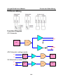
1
ioLogik R2140 User’s Manual First Edition, January 2007 www.moxa.com/product Moxa Technologies Co., Ltd. Tel: Fax: Web: +886-2-8919-1230 +886-2-8919-1231 www.moxa.com MOXA Technical Support Worldwide: [email protected] ioLogik R2140 User’s Manual The software described in this manual is furnished under a license agreement, and may be used only in accordance with the terms of that agreement. Copyright Notice Copyright © 2007 MOXA Technologies Co., Ltd. All rights reserved. Reproduction without permission is prohibited. Trademarks MOXA is a registered trademark of the MOXA Group. All other trademarks or registered marks in this manual belong to their respective manufacturers. Disclaimer Information in this document is subject to change without notice, and does not represent a commitment on the part of MOXA. MOXA provides this document “as is,” without warranty of any kind, either expressed or implied, including, but not limited to, its particular purpose. MOXA reserves the right to make improvements, and/or changes to this manual, or to the products, and/or the programs described in this manual, at any time. Information provided in this manual is intended to be accurate, and reliable. However, MOXA assumes no responsibility for its use, or for any infringements on the rights of third parties that may result from its use. This manual might include unintentional technical or typographical errors. Changes are made periodically to the information herein to correct such errors, and these changes are incorporated into new editions of the manual. Table of Contents Chapter 1. Introduction ...............................................................................................1-1 Overview .............................................................................................................................. 1-2 Product Features ................................................................................................................... 1-2 Packing List.......................................................................................................................... 1-2 Product Specifications .......................................................................................................... 1-3 Physical Dimensions ............................................................................................................ 1-4 Hardware Reference ............................................................................................................. 1-5 Panel Guide .................................................................................................................. 1-5 LED Indicators ............................................................................................................. 1-5 Chapter 2. Initial Setup ................................................................................................2-1 Hardware Installation ........................................................................................................... 2-2 Connecting the Power................................................................................................... 2-2 Grounding the ioLogik R2140...................................................................................... 2-2 Setting the RS-485 Baudrate ........................................................................................ 2-2 Setting the RS-485 Unit ID........................................................................................... 2-2 Modbus/RTU Devices .................................................................................................. 2-3 Software Installation............................................................................................................. 2-3 MXIO Library ...................................................................................................................... 2-4 Chapter 3. Using ioAdmin ...........................................................................................3-1 Introduction to ioAdmin ....................................................................................................... 3-2 Features of ioAdmin ............................................................................................................. 3-2 ioAdmin Main Screen........................................................................................................... 3-4 Main Screen Overview ................................................................................................. 3-4 Wiring Guide ................................................................................................................ 3-4 I/O Configuration Tab (General) .................................................................................. 3-6 Server Info Tab............................................................................................................. 3-6 Server Settings Tab (General) ...................................................................................... 3-7 ioAdmin Administrator Functions ........................................................................................ 3-7 I/O Configuration Tab (Administrator) ........................................................................ 3-8 Server Settings Tab (Administrator)............................................................................. 3-9 Firmware Update Tab................................................................................................. 3-10 Watchdog Tab............................................................................................................. 3-10 Server Context Menu.................................................................................................. 3-11 Chapter 4. Cascading with Other I/O Servers ...........................................................4-1 Introduction .......................................................................................................................... 4-2 Cascading System Bus ......................................................................................................... 4-2 Hardware Installation ........................................................................................................... 4-2 Using ioAdmin with Cascaded I/O Servers.......................................................................... 4-2 Adding One I/O Server................................................................................................. 4-2 Adding Two or More I/O Servers................................................................................. 4-4 Removing Cascaded I/O Servers .................................................................................. 4-6 Limitations............................................................................................................................ 4-6 Appendix A. Liquid Crystal Display Module (LCM) ..................................................... A-1 Appendix B. Modbus/RTU Address Mappings ............................................................ B-1 0xxxx Read/Write Coils (Support function 1, 5,15) .............................................................B-1 3xxxx Read only Registers (Support function 4)..................................................................B-2 4xxxx Read/Write Registers (Support function 3,6,16)........................................................B-3 Function 8.............................................................................................................................B-7 Appendix C. Factory Default Settings .......................................................................... C-2 Appendix D. Pinouts and Cable Wiring........................................................................ D-1 Serial Port Pinouts ............................................................................................................... D-1 Pin Assignment of Terminal Blocks .................................................................................... D-1 I/O Device Wiring ............................................................................................................... D-2 Function Diagram................................................................................................................ D-2 AO Schematic.............................................................................................................. D-2 AIN Schematic (voltage mode) ................................................................................... D-2 IIN Schematic (current mode) ..................................................................................... D-2 Appendix E. Service Information.................................................................................. E-1 MOXA Internet Services ......................................................................................................E-2 Technical Support E-mail Address ...............................................................................E-2 Website for Product Information ..................................................................................E-2 Problem Report Form ...........................................................................................................E-3 Product Return Procedure.....................................................................................................E-4 1 Chapter 1. Introduction The ioLogik R2140 is a stand-alone remote I/O server that can connect sensors for automation applications over an RS-485 bus. The following topics are covered in this chapter: Overview Product Features Packing List Product Specifications Physical Dimensions Hardware Reference ¾ Panel Guide ¾ LED Indicators ioLogik R2140 User’s Manual Introduction Overview The ioLogik R2140 is part of the R2000 series of ioLogik remote I/O servers, which are designed to link sensors, transmitters, transducers, and valves to an RS-485 bus. As a Moxa Easy View device, the ioLogik R2140 supports an optional hot-pluggable Liquid Crystal Display Module (LCM) to view device, bus and I/O settings such as analog input value and range. Product Features z 8 channels of mV/V/mA analog input (AI) with wire-off detection (at 4 to 20 mA) z 2 channels of analog output (AO) for voltage or current actuator control z Bundled Windows utility and quick programming library for VB, VC++, BCB z Support for SCADA software such as Wonderware InTouch and GE Intellution iFix32 z Configurable power-on and safe status AO modes z Optional hot-pluggable LCM for status display and configuration z NIST traceable calibration Packing List The ioLogik R2140 is shipped with the following items: Standard Accessories z ioLogik R2140 remote I/O server z Document & Software CD Optional Accessories z LDP1602 ioLogik Liquid Crystal Display Module (LCM) NOTE: Notify your sales representative if any of the above items are missing or damaged. 1-2 ioLogik R2140 User’s Manual Introduction Product Specifications Serial Interface Serial line protection RS-485 (2-wire): Data+, Data-, GND 15 KV ESD for all signals Serial Communication Parameters Parity None Data bits 8 Stop bits 1 Flow control None Speed 9600 to 115200 bps Protocol Modbus/RTU Built-in RTC No Analog Input Inputs Resolution Input range Data format Accuracy Sampling rate (all channels) Input impedance Built-in resistor for current input Optical isolation Overvoltage Analog Output Outputs Resolution Output range Drive voltage: Data format Accuracy CMR @ 50/60 Hz Zero drift Span drift Load resistor 8 16-bit +/-150 mV, +/-500 mV, +/-5 V, +/-10 V, 0 to 20 mA, 4 to 20 mA 16-bit integer +/- 0.1%, FSR @ 25ºC, +/- 0.3%, FSR @ -10, 60ºC 10 samples/sec (voltage); 6 samples/sec (current) 900 kΩ 125 Ω 3K VDC Can withstand continuous overvoltage (protection range -10V to 10V) 2 12-bit 0 to 10V, 4 to 20 mA 12 VDC for current output 12-bit integer +/- 0.1%, FSR @ 25ºC, +/- 0.3%, FSR @ -10, 60ºC 95 dB min. +/- 9 μV/ºC +/- 25 ppm/ºC current load < 250 Ω voltage load > 1 MΩ Power Requirements Power input Power consumption 24 VDC nominal, 12 to 48 VDC 183 mA @ 24 VDC (typ.) Mechanical Specifications Wiring I/O cable max. 14 AWG Environmental Operating temperature Storage temperature Shock Freefall Vibration -10 to 60ºC (14 to 140ºF), 5 to 95%RH -40 to 85ºC (-40 to 185ºF), 5 to 95%RH IEC60068-2-27 IEC60068-2-32 IEC60068-2-6 1-3 ioLogik R2140 User’s Manual Agency Approvals EMI EMS Safety Warranty Introduction FCC Part 15, CISPR (EN55022) Class A IEC61000-4-2 (ESD), level 2/3, IEC61000-4-3 (RS), level 2, IEC61000-4-4 (EFT), level 2, IEC61000-4-5 (Surge), level 3, IEC61000-4-6 (CS), level 2, IEC61000-4-8 (PM), level 1, IEC61000-4-11 (Dip) UL 508 2 years Physical Dimensions 1-4 ioLogik R2140 User’s Manual Introduction Hardware Reference Panel Guide (TB1) / (TB2) TB3 NOTE – The reset button restores the factory default settings. Hold the button down for 5 seconds with a pointed object such as a straightened paper clip. The RDY LED will glow red. You may release the button after the LED turns to green. LED Indicators Name PWR RDY Serial Action red off red green alternating green and red off flashing 1-5 Description Power is on Power is off System error ioLogik R2140 is functioning normally ioLogik R2140 is in Safe Status Power is off or there is a power problem. Serial port is receiving/transmitting data 2 Chapter 2. This chapter describes how to install the ioLogik R2140. The following topics are covered: Hardware Installation ¾ Connecting the Power ¾ Grounding the ioLogik R2140 ¾ Setting the RS-485 Baudrate ¾ Setting the RS-485 Unit ID ¾ Modbus/RTU Devices Software Installation MXIO Library Initial Setup ioLogik R2140 User’s Manual Initial Setup Hardware Installation Connecting the Power Connect the 12 to 48 VDC power line to the ioLogik R2140’s terminal block (TB1). If power is properly supplied, the Power LED will glow a solid red color until the system is ready ATTENTION Disconnect the power before installing and wiring Disconnect the power cord before installing and/or wiring your ioLogik R2140. Do not exceed the maximum current for the wiring Determine the maximum possible current for each power wire and common wire. Observe all electrical codes dictating the maximum current allowable for each wire size. If the current exceeds the maximum rating, the wiring could overheat, causing serious damage to your equipment. Grounding the ioLogik R2140 The ioLogik R2140 is equipped with two grounding points, one on the wall mount hole and the other on the DIN-rail mount. Setting the RS-485 Baudrate The RS-485 port on the ioLogik R2140 is reserved to chain another RS-485 I/O server. The RS-485 port can run Modbus/RTU or I/O command sets. The baudrate is set by a physical dial on the back of the ioLogik R2140. The default settings are baudrate = 115200, parity check = N, data bits = 8, and stop bit = 1. Baudrate for RS-485 (parameters are N, 8, 1) Dial setting and corresponding baudrate: 0:115200 1:57600 2:38400 3:19200 4:9600 (5 to 9 are not used) Setting the RS-485 Unit ID The ioLogik R2140 needs to be assigned a Unit ID in order to use the RS-485 bus. You may assign a number from 1 to 31. Unit ID 0 is reserved for the first devices on the RS-485 bus, such as a PC or PLC. 2-2 ioLogik R2140 User’s Manual Initial Setup Modbus/RTU Devices The RS-485 port runs Modbus/RTU and can connect to any Modbus device. You may use different methods to connect different combinations of ioLogik R2000 servers, I/O devices, and other servers. Some examples are shown below: Connecting One Serial I/O Device Connecting Multiple RS-485 I/O Devices Software Installation ioAdmin is a Windows utility that is provided with the ioLogik for configuration and management of the I/O server and attached I/O devices. It may be used from anywhere on the RS-485 bus to monitor and configure the ioLogic R2140. You may also configure some of the settings through the optional LCM. 1. Install ioAdmin from the CD-ROM: Insert the included CD into the host computer. Run SETUP.EXE, which is located in the “..\Software\Admin”directory. The installation program will guide you through the installation process. 2. Open ioAdmin: After installation is finished, run ioAdmin from Start Æ Program Files Æ ioLogik Æ Utility Æ ioAdmin. 3. Search for the server: On the menu bar, select System Æ Auto Scan Remote I/O Server. A dialog window will pop up. Make sure that “RS-232/485 I/O server” is selected and click on “Port Settings” to set/verify the serial port. Click Start Search to begin searching for the ioLogik R2140. It will take several minutes to scan all ports and devices. 2-3 ioLogik R2140 User’s Manual Initial Setup You may click “Stop” as soon as your ioLogik R2140 appears on the list. Otherwise, ioAdmin will continue to searching all 99 RS-485 Unit IDs. 4. Monitor status of I/O devices: Once the ioLogik R2140 is found by ioAdmin, you may view the status of all I/O devices on ioAdmin’s main screen. You may now use ioAdmin to setup or configure your the ioLogik R2140. MXIO Library MOXA provides a Windows library for the ioLogik R2140. To install the library, run SETUP.EXE, which is located in the “..\Software\MXIO2012\”directory. The program will guide you through the installation process. 2-4 3 Chapter 3. Using ioAdmin This chapter goes over the functions available in ioAdmin, the main configuration and management utility for the ioLogik R2140. The following topics are covered: Introduction to ioAdmin Features of ioAdmin ioAdmin Main Screen ¾ Main Screen Overview ¾ Wiring Guide ¾ I/O Configuration Tab (General) ¾ Server Info Tab ¾ Server Settings Tab (General) ioAdmin Administrator Functions ¾ I/O Configuration Tab (Administrator) ¾ Server Settings Tab (Administrator) ¾ Firmware Update Tab ¾ Watchdog Tab ¾ Server Context Menu ioLogik R2140 User’s Manual Using ioAdmin Introduction to ioAdmin ioLogik remote I/O servers may be managed and configured over the RS-485 bus by ioAdmin, a Windows 2000/XP utility provided with your ioLogik R2140. ioAdmin’s graphical-user interface gives you easy access to all status information and settings. Features of ioAdmin Remote Management Over the RS-485 bus, ioAdmin allows users to z z z z find and configure multiple ioLogik servers. monitor and configure attached I/O devices. test I/O devices. reset the server. On-line Wiring Guide An on-line wiring guide can be opened from within ioAdmin for your convenience. The easily accessible wiring guide can save administrators much time while planning or troubleshooting. 3-2 ioLogik R2140 User’s Manual Configuration File ioAdmin allows the configuration of the ioLogik R2140 to be saved as a file. The file is viewable as text and can serve z z z as a record or backup of configuration. as a template for the configuration of other servers. as a quick reference guide for you to configure Modbus drivers in a SCADA system. The configuration file includes the following information: 1. 2. 3. Title, file date and time Model information Modbus address table Using ioAdmin ioLogik R2140 Network I/O Server Configuration ============================================= Date: 2006/11/2 Time: 08:49:40 AM [1. Model] ---------MOD_TYPE=R2140 - RS-485 Remote I/O Server (8AI + 2AO) MOD_LOC= MOD_NAME= [2. I/O Configurations] ----------------------AI00=0,(+/-150mV) AI01=0,(+/-150mV) AI02=1,(+/-500mV) AI03=2,(+/-5V) AI04=3,(+/-10V) AI05=4,(0-20mA) AI06=5,(4-20mA) AI07=0,(+/-150mV) AO00=0,(0-10V), AO01=0,(0-10V), [3. Modbus address table] ------------------------CHANNEL I/O TYPE (Dec, Hex) AI00 Input AI01 Input AI02 Input AI03 Input AI04 Input AI05 Input AI06 Input AI07 Input AO00 Output AO01 Output <END> 3-3 AO00_PWN=0,(RAW), AO01_PWN=0,(RAW), AO00_SAFE=0,(RAW) AO01_SAFE=0,(RAW) MODBUS REFERENCE MODBUS ADDRESS 30001 30002 30003 30004 30005 30006 30007 30008 40001 40002 0000, 0001, 0002, 0003, 0004, 0005, 0006, 0007, 0000, 0001, 0x0000 0x0001 0x0002 0x0003 0x0004 0x0005 0x0006 0x0007 0x0000 0x0001 ioLogik R2140 User’s Manual Using ioAdmin ioAdmin Main Screen Main Screen Overview ioAdmin’s main screen is shown below. The main window defaults to the I/O Configuration tab, which displays a graphic of the ioLogik R2140 and the status of every I/O channel below it. The other tabs in the main window take you to server and bus settings, and further functions are available when you log on as an administrator. Note that you must log on as an administrator to gain access to configuration options. 1 3 2 4 5 6 7 ioAdmin Main Screen 1. Title 2. Menu bar 3. Quick link 4. Navigation panel 5. Main window 6. Sync. rate status 7. Status bar Wiring Guide ioAdmin provides a wiring guide for the ioLogik R2140. You may view the wiring guide by right-clicking the graphic of the ioLogik R2140 in the I/O Configuration tab. Select “Wiring Guide” in the submenu to open a help file showing the wiring information and electrical characteristics of the ioLogik R2140. 3-4 ioLogik R2140 User’s Manual Using ioAdmin You may also access the wiring guide through the Help menu on the menu bar. 3-5 ioLogik R2140 User’s Manual Using ioAdmin I/O Configuration Tab (General) The I/O Configuration tab shows the status of every I/O channel underneath a graphic of the ioLogik R2140. This is the default tab when you first open ioAdmin. Server Info Tab Server information, such as firmware version, is displayed in the Server Info tab. 3-6 ioLogik R2140 User’s Manual Using ioAdmin Server Settings Tab (General) The Server Settings tab is where you log in as an administrator. This is required in order to gain access to the ioLogik R2140 configuration options. If no administrator password has been set up, simply click on Login and leave the Password for entry field blank. Please refer to the ioAdmin Administrator Functions section later on in this chapter for more detail. ioAdmin Administrator Functions For full access to all configuration options, log in as an administrator in the Server Settings tab. This is required whenever you start up ioAdmin or boot up/restart the ioLogik R2140. When you install the ioLogik R2140 for the first time, the password will be blank and you may simply click on Login. Additional functions will available after logging in, including the following new tabs: When making configuration changes, you will need to click on Update or on Apply to save the changes. Some changes will not take effect until the ioLogik R2140 is restarted. You will be given the option to restart the server if necessary. ATTENTION You must log in to access administrator functions such as the Watchdog and Firmware Update tabs. If you forget the password, you may hold down the Reset button on the ioLogik R2140 to clear the password and load factory defaults. This will result in the loss of all configuration settings! 3-7 ioLogik R2140 User’s Manual Using ioAdmin I/O Configuration Tab (Administrator) When logged on as an administrator, you may double click on a channel in the I/O Configuration tab to configure that channel’s settings. Configuring Analog Input Channels The ioLogik R2140 is equipped with 8 AI (analog input) channels that can be set individually to +/-150 mV, +/-500 mV, +/-5V, +/-10V, 0-20 mA, and 4-20 mA. Configuring Analog Output Channels The ioLogik R2140 is equipped with 2 AO (analog output) channels that can be set individually to 0-10V, 4-20 mA. Power On Settings: Use this field to set the initial value for the AO channel when the ioLogik R2140 is powered on. The Power On Settings field uses raw data values. If you do not know how to translate the raw data values into real values, use the Test function for assistance. Safe Status Settings: Use this field to specify how the AO channel responds to a break in RS-485 communication. When the connection is lost for the amount of time specified in the Host Connection Watchdog, the ioLogik R2140 enters Safe Status, and the AO channel’s Safe Status settings will go into effect. Note that the Host Connection Watchdog is disabled by default. If the 3-8 ioLogik R2140 User’s Manual Using ioAdmin Host Connection Watchdog is disabled, the ioLogik R2140 will never enter Safe Status and the Safe Status settings will have no effect. Test I/O: You can test the AO channel in the Test tab, Note that the slider shows both the raw data value and the V/mA value. You may use this as a guide when entering values for the Power On and Safe Status settings. Server Settings Tab (Administrator) You may set up a password, server name, and location in the Server Settings tab. 3-9 ioLogik R2140 User’s Manual Using ioAdmin Firmware Update Tab The ioLogik R2140 supports remote firmware updates through the Firmware Update tab. Enter the path to the firmware file or click on the icon to browse for the file. Click on Update to update the firmware. The wizard will lead you through the process until the server is restarted. WARNING Do not interrupt the firmware update process! An interruption in the process may result in your device becoming unrecoverable. After the firmware is updated, the ioLogik will restart and you will have to log in again to access administrator functions. Watchdog Tab The Watchdog tab is where you configure the Host Connection Watchdog, which is used with the Safe Status settings to define each AO channel’s response to a lost RS-485 connection. When the ioLogik R2140 loses its RS-485 connection for the specified amount of time, the Host Connection Watchdog will initiate Safe Status and all AO channels will reset to their Safe Status settings. By default, the Watchdog is disabled, which means that the Safe Status settings will not have any effect. To enable the Watchdog, check off Enable Host Connection Watchdog, set the Timeout value, and restart the server. 3-10 ioLogik R2140 User’s Manual Using ioAdmin Server Context Menu The Server context menu is accessed by right clicking on the server model name in the navigation panel. Connect Select this command to try re-establishing a connection over the RS-485 bus between ioAdmin and the selected ioLogik server. Disconnect Select this command to drop the RS-485 connection between ioAdmin and the selected ioLogik server. Delete I/O Server Select this command to remove the selected server from ioAdmin’s list of available servers. Add Serial I/O Server Select this command to manually add a server. Restart System Select this command to restart the ioLogik R2140 from a remote site Reset to Default Select this command to reset all settings, including console password, to factory default values. Export System Config Select this command to export the configuration of the ioLogik R2140 to a text file. It is strongly recommended you use this method to back up your configuration after you have finished configuring the ioLogik R2140 for your application. Below is an example of the exported configuration file. The file includes information on the model, I/O configuration, and Modbus addresses. 3-11 ioLogik R2140 User’s Manual Using ioAdmin ioLogik R2140 Network I/O Server Configuration ============================================= Date: 2006/11/2 Time: 08:49:40 AM [1. Model] ---------MOD_TYPE=R2140 - RS-485 Remote I/O Server (8AI + 2AO) MOD_LOC= MOD_NAME= [2. I/O Configurations] ----------------------AI00=0,(+/-150mV) AI01=0,(+/-150mV) AI02=1,(+/-500mV) AI03=2,(+/-5V) AI04=3,(+/-10V) AI05=4,(0-20mA) AI06=5,(4-20mA) AI07=0,(+/-150mV) AO00=0,(0-10V), AO01=0,(0-10V), AO00_PWN=0,(RAW), AO01_PWN=0,(RAW), [3. Modbus address table] ------------------------CHANNEL I/O TYPE MODBUS REFERENCE AI00 Input 30001 AI01 Input 30002 AI02 Input 30003 AI03 Input 30004 AI04 Input 30005 AI05 Input 30006 AI06 Input 30007 AI07 Input 30008 AO00 Output 40001 AO01 Output 40002 AO00_SAFE=0,(RAW) AO01_SAFE=0,(RAW) MODBUS ADDRESS (Dec, Hex) 0000, 0x0000 0001, 0x0001 0002, 0x0002 0003, 0x0003 0004, 0x0004 0005, 0x0005 0006, 0x0006 0007, 0x0007 0000, 0x0000 0001, 0x0001 <END> Import System Config Select this command to reload a configuration that was exported to a text file. You will need to restart the ioLogik R2140 in order for the new configuration to take effect. This command may be used to restore a configuration after loading the factory defaults, or to duplicate a configuration to multiple ioLogik R2140 servers. The ioLogik R2140 imports information on the model and I/O configuration. 3-12 4 Chapter 4. Cascading with Other I/O Servers The ioLogik R2140 can act both as a standalone I/O server and as an extension module to other I/O servers. This chapter explains how to use the ioLogik R2140 as an extension module to ioLogik E2000 I/O servers. The following topics are covered: Introduction Cascading System Bus Hardware Installation Using ioAdmin with Cascaded I/O Servers ¾ Adding One I/O Server ¾ Adding Two or More I/O Servers ¾ Removing Cascaded I/O Servers Limitations ioLogik R2140 User’s Manual Cascading with Other I/O Servers Introduction The ioLogik R2140 can serve as an extension module to provide additional I/O channels to an ioLogik E2210 or E2240 Ethernet I/O server. Up to 31 units can be chained or cascaded together using each unit’s built-in connectors. Cascading System Bus The I/O servers connect to each other over the cascading system bus, which uses RS-485 and Modbus protocols. Pin assignments for the female system bus connector are shown below. This is the connector that protrudes from the right side of the unit. Pin 1 3 5 7 9 Signals V+ (24V) V+ (24V) N.C. Date+ Date- Pin 2 4 6 8 10 Signals VVN.C. SYNC GND Hardware Installation To install the ioLogik R2140 as an extension module, simply snap it into place alongside the ioLogik E2000 and the two units will lock together. Press the release button to detach the unit. Power is provided through the ioLogik E2000’s system bus. Depending on the power requirements of your application, external power can also be supplied to the unit through the unit’s power terminals. Using ioAdmin with Cascaded I/O Servers Adding One I/O Server ioAdmin can be used to access the I/O channels of all cascaded I/O servers. In the following instructions, the ioLogik E2210 and R2110 are used as examples: 1. Verify that the E2210 has been installed and has been opened in ioAdmin. Snap the E2210 and R2110 together. Set the unit ID for the R2110 (“2” in this example). 4-2 ioLogik R2140 User’s Manual Cascading with Other I/O Servers 2. In ioAdmin, click the E2210 in the navigation panel and select “Add Serial I/O Server” in the context menu. 3. Select the appropriate I/O Server type and UnitID (“R2110 RS-485” and “2” in this example). Click “Add”. 4-3 ioLogik R2140 User’s Manual 4. Cascading with Other I/O Servers The R2110 will appear with its unit ID under the E2210 in ioAdmin’s navigation panel. If the R2110 appears off-line, open its context menu in the navigation panel and select “Connect” to bring it on-line. Once the R2110 is on-line, you will be able to use ioAdmin to monitor and control its I/O channels. Adding Two or More I/O Servers Multiple I/O servers can be cascaded together for even more I/O channels. The following instructions show how multiple cascaded I/O servers are accessed in ioAdmin, using the ioLogik E2210, R2110, and R2140 as examples: 1. Verify that the E2210 has been installed and has been opened in ioAdmin. Snap the R2110 onto the E2210, then snap the R2140 onto the R2110. Set the unit IDs for the R2110 and R2140 (“2” and “3” in this example). 2. In ioAdmin, click the E2210 in the navigation panel and select “Add Serial I/O Server” in the context menu. 4-4 ioLogik R2140 User’s Manual Cascading with Other I/O Servers 3. Select the appropriate I/O Server type and UnitID (“R2110 RS-485” and “2” in this example). Click “Add”. 4. Repeat steps 2 and 3 using the appropriate selections for the R2140. 4-5 ioLogik R2140 User’s Manual 5. Cascading with Other I/O Servers Both the R2110 and R2140 will appear with their unit IDs under the E2210 in ioAdmin’s navigation panel. If a server appears off-line, open its context menu in the navigation panel and select “Connect” to bring it on-line. Once all I/O servers are on-line, you will be able to use ioAdmin to monitor and control each server’s I/O channels. Removing Cascaded I/O Servers To remove a cascaded I/O server in ioAdmin, click the desired server in the navigation panel and “Delete I/O Server” in the context menu. Limitations There are some limitations when using the ioLogik R2140 as an extension module to ioLogik E2000 servers. Although each I/O channel on a cascaded module can be monitored and controlled over Ethernet, the module will not support the following items: y Click&Go y Active messaging y SNMP trap messages y E-mail messages y Import/export configuration file y Upgrade firmware 4-6 A Appendix A. Liquid Crystal Display Module (LCM) As an Easy View device, the ioLogik R2140 supports an optional detachable Liquid Crystal Display Module (LCM) for easier field maintenance. The LCM is hot-pluggable and can be used to view the server’s current settings. When plugged in, the LCM displays the ioLogik R2140 “home page,” and pressing any button takes you to the configuration menu. LCM Controls The up and down buttons navigate between the current options. The right and left buttons enter and exit the submenus. On the ioLogik R2140, the center button is used only when restarting the server. Button Function Up go to the previous item Down go to the next item Left exit the current submenu and return to the previous menu (go up one level) Right enter the selected submenu (go down one level) Center enter/exit editing mode An “e” is in the upper right hand corner of the display indicates that the current field can be modified. If the “e” is not displayed, the current field may only be viewed. LCM Options Display <ioLogik R2140> ID:01 bps:115200 Explanation / Actions This is the default “home page” showing the unit ID and baudrate. Press the down button to begin navigating the menus. <ioLogik R2140> server Enter this submenu to display information about the specific server you are viewing: z serial number z name z location z R2140 f/w ver z lcm f/w ver z model name <ioLogik R2140> serial port Enter this submenu to display the RS-485 cascade port settings. ioLogik R2140 User’s Manual Display <ioLogik R2140> i/o setting <ioLogik R2140> save/restart Liquid Crystal Display Module (LCM) Explanation / Actions Enter this submenu to view I/O channel status. Press up or down to navigate through the different I/O channels without having to go back to the previous menu. Enter this submenu to display the restart now submenu. Enter the restart now submenu to display the restart option. Press the center button to modify this option, then select enable to reboot the I/O server. The disable option has no effect. A-2 B Appendix B. Modbus/RTU Address Mappings 0xxxx Read/Write Coils (Support function 1, 5,15) Reference 00001 Address 0x0000 Data Type 1bit 00002 0x0001 1bit 00003 0x0002 1bit 00004 0x0003 1bit 00005 0x0004 1bit 00006 0x0005 1bit 00007 0x0006 1bit 00008 0x0007 1bit 00009 0x0008 1bit Description Reset CH0 AI Min Value Read: always 0 Write: 1: reset AI Min value 0: return Illegal Data Value Reset CH1 AI Min Value Read: always 0 Write : 1: reset AI Min value 0: return Illegal Data Value Reset CH2 AI Min Value Read: always 0 Write : 1: reset AI Min value 0: return Illegal Data Value Reset CH3 AI Min Value Read: always 0 Write : 1: reset AI Min value 0: return Illegal Data Value Reset CH4 AI Min Value Read: always 0 Write : 1: reset AI Min value 0: return Illegal Data Value Reset CH5 AI Min Value Read: always 0 Write : 1: reset AI Min value 0: return Illegal Data Value Reset CH6 AI Min Value Read: always 0 Write : 1: reset AI Min value 0: return Illegal Data Value Reset CH7 AI Min Value Read: always 0 Write : 1: reset AI Min value 0: return Illegal Data Value Reset CH0 AI Max Value Read: always 0 Write : 1: reset AI Max value 0: return Illegal Data Value ioLogik R2140 User’s Manual Reference 00010 Address 0x0009 Data Type 1bit 00011 0x000A 1bit 00012 0x000B 1bit 00013 0x000C 1bit 00014 0x000D 1bit 00015 0x000E 1bit 00016 0x000F 1bit Modbus/TCP Address Mappings Description Reset CH1 AI Max Value Read: always 0 Write : 1: reset AI Max value 0: return Illegal Data Value Reset CH2 AI Max Value Read: always 0 Write : 1: reset AI Max value 0: return Illegal Data Value Reset CH3 AI Max Value Read: always 0 Write : 1: reset AI Max value 0: return Illegal Data Value Reset CH4 AI Max Value Read: always 0 Write : 1: reset AI Max value 0: return Illegal Data Value Reset CH5 AI Max Value Read: always 0 Write : 1: reset AI Max value 0: return Illegal Data Value Reset CH6 AI Max Value Read: always 0 Write : 1: reset AI Max value 0: return Illegal Data Value Reset CH7 AI Max Value Read: always 0 Write : 1: reset AI Max value 0: return Illegal Data Value 3xxxx Read only Registers (Support function 4) Reference 30001 30002 30003 30004 30005 30006 30007 30008 30009 30010 30011 30012 30013 30014 30015 30016 30017 30018 30019 Address 0x0000 0x0001 0x0002 0x0003 0x0004 0x0005 0x0006 0x0007 0x0008 0x0009 0x000A 0x000B 0x000C 0x000D 0x000E 0x000F 0x0010 0x0011 0x0012 Data Type 1 word 1 word 1 word 1 word 1 word 1 word 1 word 1 word 1 word 1 word 1 word 1 word 1 word 1 word 1 word 1 word 1 word 1 word 1 word Description CH0 Read AI Value CH1 Read AI Value CH2 Read AI Value CH3 Read AI Value CH4 Read AI Value CH5 Read AI Value CH6 Read AI Value CH7 Read AI Value CH0 Read AI Min Value CH1 Read AI Min Value CH2 Read AI Min Value CH3 Read AI Min Value CH4 Read AI Min Value CH5 Read AI Min Value CH6 Read AI Min Value CH7 Read AI Min Value CH0 Read AI Max Value CH1 Read AI Max Value CH2 Read AI Max Value B-2 ioLogik R2140 User’s Manual Reference 30020 30021 30022 30023 30024 Address 0x0013 0x0014 0x0015 0x0016 0x0017 Data Type 1 word 1 word 1 word 1 word 1 word Modbus/TCP Address Mappings Description CH3 Read AI Max Value CH4 Read AI Max Value CH5 Read AI Max Value CH6 Read AI Max Value CH7 Read AI Max Value 4xxxx Read/Write Registers (Support function 3,6,16) Address 0x0000 0x0001 0x0002 0x0003 0x0004 0x0005 0x0006 Data Type 1 word 1 word 1 word 1 word 1 word 1 word 1 word 0x0007 1 word 0x0008 1 word 0x0009 1 word 0x000A 1 word 0x000B 1 word 0x000C 1 word Description CH0 AO Value (0 ~ 4095) CH1 AO Value (0 ~ 4095) CH0 AO PowerOn Value (0 ~ 4095) CH1 AO PowerOn Value (0 ~ 4095) CH0 AO Safe Value (0 ~ 4095) CH1 AO Safe Value (0 ~ 4095) CH0 AO Range 0: 0-10 VDC 1: 4-20 mA Others: return Illegal Data Value CH1 AO Range 0: 0-10 VDC 1: 4-20 mA Others: return Illegal Data Value CH0 AO PowerOn Range 0: 0-10 VDC 1: 4-20 mA Others: return Illegal Data Value CH1 AO PowerOn Range 0: 0-10 VDC 1: 4-20 mA Others: return Illegal Data Value CH0 AO Safe Range 0: 0-10 VDC 1: 4-20 mA Others: return Illegal Data Value CH1 AO Safe Range 0: 0-10 VDC 1: 4-20 mA Others: return Illegal Data Value CH0 AI Range 00: +/-150 mV 01: +/-500 mV 02: +/-5V 03: +/-10V 04: 0-20 mA 05: 4-20 mA Others: return Illegal Data Value B-3 ioLogik R2140 User’s Manual Address 0x000D Data Type 1 word 0x000E 1 word 0x000F 1 word 0x0010 1 word 0x0011 1 word 0x0012 1 word Modbus/TCP Address Mappings Description CH1 AI Range 00: +/-150 mV 01: +/-500 mV 02: +/-5V 03: +/-10V 04: 0-20 mA 05: 4-20 mA Others: return Illegal Data Value CH2 AI Range 00: +/-150 mV 01: +/-500 mV 02: +/-5V 03: +/-10V 04: 0-20 mA 05: 4-20 mA Others: return Illegal Data Value CH3 AI Range 00: +/-150 mV 01: +/-500 mV 02: +/-5V 03: +/-10V 04: 0-20 mA 05: 4-20 mA Others: return Illegal Data Value CH4 AI Range 00: +/-150 mV 01: +/-500 mV 02: +/-5V 03: +/-10V 04: 0-20 mA 05: 4-20 mA Others: return Illegal Data Value CH5 AI Range 00: +/-150 mV 01: +/-500 mV 02: +/-5V 03: +/-10V 04: 0-20 mA 05: 4-20 mA Others: return Illegal Data Value CH6 AI Range 00: +/-150 mV 01: +/-500 mV 02: +/-5V 03: +/-10V 04: 0-20 mA 05: 4-20 mA Others: return Illegal Data Value B-4 ioLogik R2140 User’s Manual Address 0x0013 Data Type 1 word 0x0014 1 word 0x0015 1 word 0x0016 1 word 0x0017 1 word 0x0018 1 word Modbus/TCP Address Mappings Description CH7 AI Range 00: +/-150 mV 01: +/-500 mV 02: +/-5V 03: +/-10V 04: 0-20 mA 05: 4-20 mA Others: return Illegal Data Value CH0 AI PowerOn Range 00: +/-150 mV 01: +/-500 mV 02: +/-5V 03: +/-10V 04: 0-20 mA 05: 4-20 mA Others: return Illegal Data Value CH1 AI PowerOn Range 00: +/-150 mV 01: +/-500 mV 02: +/-5V 03: +/-10V 04: 0-20 mA 05: 4-20 mA Others: return Illegal Data Value CH2 AI PowerOn Range 00: +/-150 mV 01: +/-500 mV 02: +/-5V 03: +/-10V 04: 0-20 mA 05: 4-20 mA Others: return Illegal Data Value CH3 AI PowerOn Range 00: +/-150 mV 01: +/-500 mV 02: +/-5V 03: +/-10V 04: 0-20 mA 05: 4-20 mA Others: return Illegal Data Value CH4 AI PowerOn Range 00: +/-150 mV 01: +/-500 mV 02: +/-5V 03: +/-10V 04: 0-20 mA 05: 4-20 mA Others: return Illegal Data Value B-5 ioLogik R2140 User’s Manual Address 0x0019 Data Type 1 word 0x001A 1 word 0x001B 1 word 0x001C 1 word 0x001D 1 word 0x001E 1 word Modbus/TCP Address Mappings Description CH5 AI PowerOn Range 00: +/-150 mV 01: +/-500 mV 02: +/-5V 03: +/-10V 04: 0-20 mA 05: 4-20 mA Others: return Illegal Data Value CH6 AI PowerOn Range 00: +/-150 mV 01: +/-500 mV 02: +/-5V 03: +/-10V 04: 0-20 mA 05: 4-20 mA Others: return Illegal Data Value CH7 AI PowerOn Range 00: +/-150 mV 01: +/-500 mV 02: +/-5V 03: +/-10V 04: 0-20 mA 05: 4-20 mA Others: return Illegal Data Value CH0 AI Safe Range 00: +/-150 mV 01: +/-500 mV 02: +/-5V 03: +/-10V 04: 0-20 mA 05: 4-20 mA Others: return Illegal Data Value CH1 AI Safe Range 00: +/-150 mV 01: +/-500 mV 02: +/-5V 03: +/-10V 04: 0-20 mA 05: 4-20 mA Others: return Illegal Data Value CH2 AI Safe Range 00: +/-150 mV 01: +/-500 mV 02: +/-5V 03: +/-10V 04: 0-20 mA 05: 4-20 mA Others: return Illegal Data Value B-6 ioLogik R2140 User’s Manual Address 0x001F Data Type 1 word 0x0020 1 word 0x0021 1 word 0x0022 1 word 0x0023 1 word Modbus/TCP Address Mappings Description CH3 AI Safe Range 00: +/-150 mV 01: +/-500 mV 02: +/-5V 03: +/-10V 04: 0-20 mA 05: 4-20 mA Others: return Illegal Data Value CH4 AI Safe Range 00: +/-150 mV 01: +/-500 mV 02: +/-5V 03: +/-10V 04: 0-20 mA 05: 4-20 mA Others: return Illegal Data Value CH5 AI Safe Range 00: +/-150 mV 01: +/-500 mV 02: +/-5V 03: +/-10V 04: 0-20 mA 05: 4-20 mA Others: return Illegal Data Value CH6 AI Safe Range 00: +/-150 mV 01: +/-500 mV 02: +/-5V 03: +/-10V 04: 0-20 mA 05: 4-20 mA Others: return Illegal Data Value CH7 AI Safe Range 00: +/-150 mV 01: +/-500 mV 02: +/-5V 03: +/-10V 04: 0-20 mA 05: 4-20 mA Others: return Illegal Data Value Function 8 Address 0x0001 0x0001 Data Field(Request) 0x0000 0xFF00 Data Field (Response) Echo Request Data Echo Request Data B-7 Description Reboot Reset to factory default C Appendix C. Factory Default Settings The ioLogik R2140 is configured with the following factory defaults: RS-485 Unit ID: Default baud rate: Communication watchdog: 1 115,200bps Disable AI Input Range: AO Output Range: AO Safe Status: Power on status: -10 to 10V 0 to 10V Off, 0V Off, 0V Password: Server Name: Server Location: NONE NONE NONE D Appendix D. Pinouts and Cable Wiring Serial Port Pinouts R2140 RS-485 Modbus Adapter Pin Assignment Pin Assignment of Terminal Blocks Power/RS-485 Pin 1 2 3 4 5 6 Signal V+ V- FG D+ D- SG lout1- lout1+ Vout1- Vout1+ lout0- lout0+ Vout0- Vout0+ Vin7- Vin7+ Vin6- Vin6+ Vin5- Vin5+ Vin4- Vin4+ Vin3- Vin3+ Vin2- Vin2+ Vin1- Vin1+ Vin0- Vin0+ I/O (left to right) Pin 1 2 3 4 5 6 7 8 9 10 11 12 Signal Vin0+ Vin0- Vin1+ Vin1- Vin2+ Vin2- Vin3+ Vin3- Vin4+ Vin4- Vin5+ Vin5- Pin 13 14 15 16 17 18 19 20 21 22 23 24 Signal Vin6+ Vin6- Vin7+ Vin7- Vout0+ Vout0- Iout0+ Iout0- Vout1+ Vout1- Iout1+ Iout1- ioLogik R2140 User’s Manual Pinouts and Cable Wiring I/O Device Wiring Function Diagram AO Schematic + Vout DAC MCU Iout AIN Schematic (voltage mode) AI+ MUX ADC MCU ADC MCU AI- IIN Schematic (current mode) AI+ 125 ohm MUX AI- D-2 E Appendix E. Service Information This appendix shows you how to contact MOXA for information about the ioLogik R2140, and other products, and how to report problems. In this appendix, we cover the following topics. MOXA Internet Services Problem Report Form Product Return Procedure ioLogik R2140 User’s Manual Service Information MOXA Internet Services Customer satisfaction is our top priority. To ensure that customers receive the full benefit of our products, MOXA Internet Services has been set up to provide technical support, driver updates, product information, and user’s manual updates. The following services are provided Technical Support E-mail Address [email protected] Website for Product Information http://www.moxa.com E-2 ioLogik R2140 User’s Manual Service Information Problem Report Form MOXA ioLogik R2140 Remote I/O Server Customer name: Company: Tel: Fax: Email: Date: MOXA Product: ioLogik R2140 Serial Number: _________________ Problem Description: Please describe the symptoms of the problem as clearly as possible, including any error messages you see. A clearly written description of the problem will allow us to reproduce the symptoms, and will expedite the repair of your product. E-3 ioLogik R2140 User’s Manual Service Information Product Return Procedure For product repair, exchange, or refund, the customer must complete each of the following: z Provide evidence of original purchase. z Obtain a Product Return Agreement (PRA) from the sales representative or dealer. z Fill out the Problem Report Form (PRF) with as much detail as possible to minimize repair time. z Carefully pack the product in an anti-static package and send it, pre-paid, to the dealer. The PRA should be visible on the outside of the package and should include a description of the problem along with the return address and telephone number. E-4