1
Genion_ii_00111.qxd
7/4/02
11:39 AM
Page 1
www.philipscsi.com
LTC 0435 & LTC 0455
SERIES COLOR CAMERAS
I N S TA L L AT I O N
INSTRUCTIONS
EN
FR
DE
ES
NL
IT
PT
ZH
Philips
Communication,
Security & Imaging
Genion_ii_00111.qxd
7/4/02
11:39 AM
Page 2
IMPORTANT SAFETY INSTRUCTIONS
13.
The lighting flash with arrowhead sysbol,
within an equilateral triangle, is intended
to alert the user to the presence of
uninsulated "dangerous voltage" within the
product's enclosure that may be of
sufficient magnitude to constitute a risk to
persons.
The exclamation point, within an
equilateral triangle, is intended to alert the
user to the presence of important operating
and maintenance accompanying the
appliance.
1.
2.
3.
4.
5.
6.
7.
8.
9.
10.
11.
12.
Read these instructions
Keep these instructions.
Heed all Warnings.
Follow all instructions.
Do not use the apparatus near water.
Clean with a dry cloth only.
Do not install near heat sources such as
radiators, heat registers, stoves, or other
apparatus that generates heat (including
amplifiers).
Do not defeat the purpose of a polarized or
grounded mains plug. A polarized plug has
dissimilar prongs (one wider than the other) to
ensure correct polarity, while a grounded plug
has an additional 'ground' prong provided for
your safety. If the plug supplied with the
apparatus does not fit into your outlet, consult
an electrician for advice.
Protect the power-supply cord from being
walked on or pinched, particularly close to
plugs, receptacles and the point where it exits
from the apparatus.
Only use attachments and accessories
(including stands, tripods, mounting brackets
and housings) specified or recommended by the
manufacturer.
Unplug the apparatus during lightning storms
and when unused for extended periods.
Do not attempt to service this unit yourself as
opening or removing covers may expose you to
dangerous voltage or other hazards. Refer all
servicing to qualified service personnel.
14.
Servicing is required when the apparatus does
not function in the normal way, has been
dropped, if liquid has been spilled on it, or if it
has been exposed to rain or water. Unplug the
unit from the outlet and refer servicing to
qualified service personnel.
An all-pole mains switch with contact
separation of at least 3 mm in each pole shall be
incorporated in the electrical installation of the
building.
Warning
To reduce the risk of fire or electric shock, do not
expose this apparatus to rain or moisture.
FCC Information
Caution: Any changes or modifications to
construction of this device that are not expressly
approved by the party responsible for compliance
could void the user’s authority to operate the
equipment.
This equipment has been tested and found to comply
with the limits for a Class B digital device, pursuant
to part 15 of the FCC Rules. These limits are
designed to provide reasonable protection against
harmful interference in a residential installation. This
equipment generates, uses and can radiate radio
frequency energy and, if not installed and used in
accordance with the instructions, may cause harmful
interference to radio communications. However, there
is no guarantee that interference to radio or television
reception, which can be determined by turning the
equipment off and on, the user is encouraged to try
to correct the interference by one or more of the
following measures:
•
Re-orient or relocate the receiving antenna.
•
Increase the separation between the equipment
and receiver.
•
Connect the equipment into an outlet on a
circuit different from that to which the receiver
is connected.
•
Consult the dealer or an experienced radio/TV
technician for help.
7/4/02
11:39 AM
Page EN1
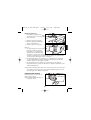
SPECIFICATIONS
Standard
Active pixels (H x V)
Imager
Resolution
Minimum illumination
Signal-to-noise ratio
Video output
Y/C output
Synchronization
Shutter
Nightsense™
Autoblack
AGC
BLC
ATW
Lens mount
ALC
Power supply
Power consumption
Dimensions (HxWxL)
Weight
Camera mount
Operating temperature
Controls
LTC 0435/x0
LTC 0455/x0
Standard resolution
High resolution
PAL
NTSC
PAL
NTSC
512 x 582
512 x 492
752 x 492 768 x 492
1/3" interline CCD
330 TV lines
480 TV lines
<0.7 lux
<0.8 lux
<0.3 lux with Nightsense™
> 50 dB
1 Vpp, 75 Ω
NA
Y: 1 Vpp, 75 Ω;
C: 0.3 Vpp 75 Ω
Internal or Line-Lock (selectable)
Auto / Flickerless / Off (selectable)
PAL: 1/50 - 1/125000 - NTSC: 1/60 - 1/150000
NA
Auto / Forced / Off (selectable)
On / Off (selectable)
On (0-21 dB)/ Off (0 dB) (selectable)
On / Off (selectable)
Auto/Hold selectable 2500 to 9000 K
C and CS compatible
Video-iris or DC-iris (auto detect)
LTC 04x5/10 & /20: 12 to 28 VAC or 11 to 36 VDC
LTC 04x5/50 & /60: 85 to 265 VAC
<4 W
58 x 66 x 122 mm (2.28 x 2.6 x 4.8 inch without lens)
450 g (0.99 lbs) (without lens)
Two 1/4" 20 UNC - isolated (bottom) and
non-isolated (top)
-20°C to +50°C (-4°F to +122°F)
On-screen display (OSD) with softkey controls
Type number overview
Low voltage
High voltage
PAL (Europe) NTSC (USA) PAL (Europe) NTSC (USA)
Standard resolution LTC 0435/10 LTC 0435/20 LTC 0435/50 LTC 0435/60
High resolution
LTC 0455/10 LTC 0455/20 LTC 0455/50 LTC 0455/60
EN1
English
Genion_ii_00111.qxd
English
Genion_ii_00111.qxd
7/4/02
11:39 AM
Page EN2
UNPACKING
Unpack carefully and handle the equipment with care. The packaging contains:
• Camera
• CCD protection cap
• Spare lens connector (male)
• These Instructions
Note: If equipment appears to have been damaged during shipment, repack it in the
original packaging and notify the shipping agent or supplier.
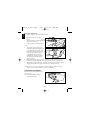
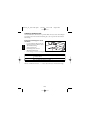
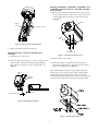
CONNECTION
Power
LTC 04x5/10 and /20
LTC 04x5/50 and /60
To open the quick-connect, push in on the tabs.
Connections are not polarity sensitive
Use stranded or solid wire AWG16 to
AWG22, cut back 10mm (0.4") of
insulation.
Composite Video
EN2
Genion_ii_00111.qxd
7/4/02
11:39 AM
Page EN3
Pin
1
2
3
4
English
Y/C output (LTC 0455/x0 only)
Y/C Socket
GND Y
GND C
Y
C
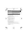
LENS MOUNTING
Pin
1
2
3
4
•
•
•
Video iris lens
Supply (11 V, 50 mA max.)
Not used
Video signal 1 Vpp, 1 kΩ
Ground
DC iris lens
DampDamp+
Drive+
Drive-
Video-iris and DC-iris lenses are recommended for the best picture performance.
The camera automatically detects the type of lens used, and optimizes
performance accordingly.
A spare male lens connector is provided if required.
Cautions:
- To avoid damaging the CCD sensor when using a C-mount lens, turn the 'green'
back-focus ring counter clockwise until it stops ('Back focus adjustment') before
mounting the lens.
- Lenses weighing more than 0.5 kg (1.1lbs) must be separately supported.
Note: If a short circuit is detected on the lens connector, the on-screen display (OSD)
failure message 'LENS SHORT CIRCUIT' is shown. The lens circuit is
automatically disabled to avoid internal damage. Remove the lens connector and
check the pin connections.
EN3
English
Genion_ii_00111.qxd
7/4/02
11:39 AM
Page EN4
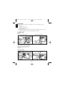
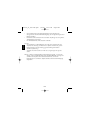
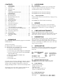
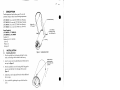
Back focus adjustment
• Camera accepts both C and CS-mount lenses.
1.
2.
3.
Unlock the back focus locking
button.
Turn the back focus adjustment as
required. (See Note 1).
Lock the back focus locking button.
Notes:
1. To optimize picture sharpness in
both bright and low-level lighting, it
is recommended to adjust the back
focus when carrying out the set-up
procedure. The camera's unique
'Lens Wizard' allows focusing at
maximum lens opening to ensure
that the object of interest always
remains in focus.
2. When back focusing vari-focus lenses, it must be possible to obtain a sharp
picture in both wide-angle and tele positions, and for both far and near focus.
3. When back focusing zoom lenses, ensure the object of interest remains in focus
throughout the entire zoom range of the lens. (See Advanced Set up).
Caution: Do not point the camera/lens into direct sunlight. When viewing an
outdoor scene, a video- or DC-iris lens is recommended.
MOUNTING THE CAMERA
The camera can be mounted from the
top or bottom.
Note: The BOTTOM mounting is
isolated from ground.
EN4
7/4/02
11:39 AM
Page EN5
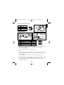
ADVANCED SET-UP
The camera will normally give an optimal picture without the need for further
adjustments. However for special circumstances advanced set up options are available.
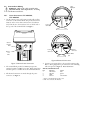
Accessing and navigating menus
• Five softkeys are used for navigating
menus (located under the side panel).
• To access set-up menus, press the
menu/select key.
• The main menu appears on the OSD.
•
Key
Function
Menu button (O) Access the menus, or move to next or previous menu.
←→
Toggle through options, set parameters
↑↓
Scroll up and down menu
↓
Note: A downward-pointing arrow (
) indicates a sub-menu follows.
EN5
English
Genion_ii_00111.qxd
English
Genion_ii_00111.qxd
7/4/02
11:39 AM
Page EN6
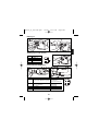
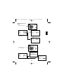
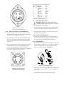
Menu Navigation
Press the menu button
MAIN MENU
LEVEL
SHUT/AGC
BLC
COLOR
SYNC
VPHASE
SHUT/AGC MENU
0
OFF
ATW
LINE LOCK
0°
SHUTTER
AGC
AUTOBLACK
NIGHTSENSE
AES
ON
ON
OFF
EXIT
EXIT
Shutter/AGC Menu
Main Menu
COLOR MENU
WHITE BAL
RED-GAIN
BLUE-GAIN
ATW
0
0
EXIT
Color Menu
Press the menu button
for more than 5sec.
LENS WIZARD
DETECTED LENS
DCIRIS
SET BACK FOCUS NOW
INSTALLER
VERSION
LENS
SPEED
WIZARD
DEFAULTS
00.0010.XX
AUTO
FAST
EXIT
LENS WIZARD
DETECTED LENS
VIDEO
SET BACK FOCUS NOW
EXIT
SET LVL
Installer Menu
Lens Wizard Menus
EN6
EXIT
7/4/02
11:39 AM
Page EN7
Main menu
Function
LEVEL
SHUT/AGC
BLC
Selection
-15 - 0 - +15
Select next menu
ON
OFF
COLOR*
ATW
ATB HOLD
Select next menu
LINE LOCK
INTERNAL
SYNC
V PHASE
0-358˚
EXIT
Description
Adjusts video level.
Shutter / Automatic Gain Control menu.
When 'ON', the level is optimized at the center of
the screen. Parts outside the center may be under- or
over-exposed (this is normal).
Select to access the color menu. (See Color menu
for detailed explanation).
Select 'LINE LOCK' to synchronize with the power
supply frequency. Select 'INTERNAL' for use with
internal synchronization (automatically selected with
DC supply).
Adjusts the vertical phase offset (when in
'LINE LOCK' mode).
Exit the menu.
*Note: If the camera (LTC 0455/x0 only) is in black & white high sensitivity mode
(via NightSense™), the color settings and color menu are not accessible. The
NightSense™ sensitivity boost must be selected OFF to make color adjustments.
Shutter/AGC menu
Function
SHUTTER
Selection
AES
FL
OFF
AGC
AUTOBLACK
ON/OFF
ON/OFF
NIGHTSENSE
AUTO
FORCED
OFF
EXIT
Description
(AES) Auto-shutter sets the optimum shutter speed
for manual iris lenses. (FL) Flickerless mode avoids
interference from light sources (recommended for use
with video-iris or DC-iris lenses only).
Automatic gain control
Autoblack automatically increases the visibility
of details.
Nightsense™* extends the low-light
performance of the camera. AUTO mode, the
camera automatically inches to monochrome
in low-light conditions. In Forced mode, the picture
remains a high-sensitivity monochrome image.
Some active noise or white spots may appear in the
picture.
Exit this menu.
*Note: NightSense™ is only available on the LTC 0455/x0 cameras.
EN7
English
Genion_ii_00111.qxd
English
Genion_ii_00111.qxd
7/4/02
11:39 AM
Page EN8
Color menu
Note: Auto Tracking White Balance must be selected OFF.
Function
WHITE BAL
Selection
ATW
AWB HOLD
RED- GAIN*
-5 - 0 - +5
BLUE- GAIN*
-5 - 0 - +5
EXIT
Description
ATW: Auto tracking white balance allows the
camera to constantly adjust for optimal color
reproduction.
AWB HOLD: Puts the ATW on hold and saves
the color settings.
Offset factory white point alignment (reducing
red introduces more cyan).
Offset factory white point alignment (reducing
blue introduces more yellow).
Exit the menu.
*Note: For special scene conditions only, it will be necessary to change the white
point offsets.
Accessing installer menu
• To access the installer menu, press and hold the menu/select key for five seconds.
Installer menu
Function
VERSION
Selection
LENS
AUTO
SPEED
FAST
WIZARD
DEFAULTS
EXIT
Select next menu
Description
Read-only firmware release number (for service
purposes).
Automatically detect lens type.
A different lens type can be selected.
Selects the response time of DC-iris lenses. Some
lenses require slow lens control to avoid overshoots.
Access the lens wizard menu.
Return all set-up settings to factory defaults.
Exit the menu.
EN8
7/4/02
11:39 AM
Page EN9
Lens wizard menu
Function
SET BACK FOCUS NOW
SET LVL
EXIT
Description
Back focus the lens (see 'Back focus adjustment'). The scene is
focused at maximum lens opening to ensure that the object of
interest remains in focus in bright and low-light conditions.
When a Video-iris lens is detected, a level potentiometer is
displayed to obtain the best picture performance. The lens
wizard includes a level detector meter that must be set to the
center using the potentiometer for best results.
Exit the menu.
Adjustment procedure DC-iris Lens:
1. Unlock the back focus locking button.
2. Access the "Lens Wizard" menu.
3. The "SET BACK FOCUS NOW" option is highlighted in the menu.
4. Turn the back focus adjustment as required.
5. Lock the back focus locking button.
6. Exit the menu.
Adjustment procedure Manual-iris Lens:
1. Unlock the back focus locking button.
2. Adjust the lens to the maximum lens opening.
3. Turn the back focus adjustment as required.
4. Lock the back focus locking button.
5. Exit the menu.
Adjustment procedure Video-iris Lens:
1. Unlock the back focus locking button.
2. Access the "Lens Wizard" menu.
3. The "SET BACK FOCUS NOW" option is highlighted in the menu.
4. Turn the back focus adjustment as required.
5. Select the "SET LVL" option in the menu, and the LEVEL bar appears.
6. Adjust the level potentiometer located on the lens until the LEVEL bar is in the
central position.
7. Lock the back focus locking button.
8. Exit the menu.
EN9
English
Genion_ii_00111.qxd
Genion_ii_00111de.qxd
7/4/02
11:41 AM
Page DE1
LTC 0435/x0
LTC 0455/x0
Standardauflösung
Hochauflösend
Standard
PAL
NTSC
PAL
NTSC
Aktive Pixel (H x V)
512 x 582
512 x 492
752 x 492 768 x 492
Sensor 1/3"
Interline CCD
Auflösung
330 Bildschirmzeilen
480 Bildschirmzeilen
Minimale
<0,7 Lux
<0,8 Lux
Beleuchtungsstärke
<0,3 Lux mit Nightsense™
Signal-/Rauschabstand
> 50 dB
Videoausgang:
1 Vpp, 75 Ohm
Y/C-Ausgang
--Y: 1 Vpp, 75 Ohm
C: 0,3 Vpp, 75 Ohm
Synchronisation
Vertikalsynchronisation mit interner Frequenz oder
Netzfrequenz (wählbar)
Verschluss
Auto / Entzerrt / Aus (wählbar)
PAL: 1/50 - 1/125000 - NTSC: 1/60 - 1/150000
Nightsense™
--Auto / Immer / Aus (wählbar)
Autoblack
Ein / Aus (wählbar)
AGC
Ein (0-21 dB)/ Aus (0 dB) (wählbar)
BLC
Ein / Aus (wählbar)
ATW
Automatische Helligkeitssteuerung 2500 bis
9000 K (im "Haltebetrieb")
Objektivfassung
kompatibel mit C und CS
ALC
videogesteuerte automatische Blendenregelung oder
gleichstromgesteuerte Blende (auto detect)
Stromversorgung
LTC 04x5/10 & /20: 12 bis 28 Volt Wechselspannung
oder 11 bis 36 Volt Gleichspannung
LTC 04x5/50 & /60: 85 bis 265 V Wechselspannung
Stromaufnahme
<4 W
Abmessungen (HxBxL)
58 x 66 x 122 mm (ohne Objektiv)
Gewicht
450 g (ohne Objektiv)
Stativqewinde
1/4" 20 UNC - isoliert (unten) und nicht isoliert (oben)
Betriebstemperatur
-20°C bis +50°C
Bedienelemente
Bildschirmanzeige (OSD) mit Kurzwahltasten
DE1
Deutsch
DATEN
Genion_ii_00111de.qxd
7/4/02
11:41 AM
Page DE2
Überblick über die Typen
Deutsch
Kleinspannung
Netzspannung
PAL (Europa) NTSC (USA) PAL (Europa) NTSC (USA)
Standardauflösung LTC 0435/10 LTC 0435/20 LTC 0435/50 LTC 0435/60
Hochauflösend
LTC 0455/10 LTC 0455/20 LTC 0455/50 LTC 0455/60
AUSPACKEN
Vorsichtig auspacken und Gerät vorsichtig handhaben. Die Verpackung enthält:
• Kamera
• CCD-Schutzkappe
• Ersatz-Objektivanschluss (Stecker)
• Diese Gebrauchsanweisung
Hinweis: Wenn ein Gegenstand beim Transport beschädigt worden zu sein scheint,
verpacken Sie ihn wieder ordnungsgemäß im Originalkarton und
benachrichtigen Sie den Spediteur.
ANSCHLUSS
Stromversorgung
LTC 04x5/10 und /20
LTC 04x5/50 und /60
Klammern mit einem Schraubendreher
aufdrücken. Anschlüsse sind nicht
polaritäts-umkehrempfindlich. Litzenoder Volldraht AWG16 bis AWG22
verwenden und 10 mm Isolierung entfernen.
DE2
Genion_ii_00111de.qxd
7/4/02
11:41 AM
Page DE3
Deutsch
FBAS-Signal
Y/C-Ausgang (nur LTC 0455/x0)
Pin
1
2
3
4
Y/C-Buchse
ERDE Y
ERDE C
Y
C
EINSETZEN DES OBJEKTIVS
Pin
Objektiv mit videogesteuerter
automatischer Blendenregelung
1
Stromversorgung
(11 V, 50 mA max.)
Nicht belegt
Videosignal 1 Vpp, 1 kOhm
Erde
2
3
4
Objektiv mit
gleichstromgesteuerter Blende
DämpfungDämpfung+
Antrieb+
Antrieb-
DE3
Genion_ii_00111de.qxd
•
•
Deutsch
•
7/4/02
11:41 AM
Page DE4
Zur Gewährleistung bestmöglicher Bildqualität werden Objektive mit
videogesteuerter automatischer Blendenregelung oder mit gleichstromgesteuerter
Blende empfohlen.
Die Kamera stellt automatisch den verwendeten Objektivtyp fest und optimiert
die Bildqualität entsprechend.
Für den Bedarfsfall ist ein Ersatzstecker vorhanden.
Vorsicht:
- Zur Vermeidung von Beschädigungen am CCD-Sensor bei Einsetzen eines
Objektivs mit C-Fassung vor Einsetzen des Objektivs zunächst den 'grünen'
Backfocus-Ring bis an den Anschlag gegen den Uhrzeigersinn drehen
("Backfocus-Justierung").
- Objektive mit einem Gewicht von mehr als 0,5 kg benötigen eine separate
Stütze.
Hinweis: Wird am Objektivanschluss ein Kurzschluss festgestellt, so wird in der
Anzeige (OSD) die Fehlermeldung 'LENS SHORT CIRCUIT' angezeigt. Der
Stromkreis des Objektivs wird automatisch deaktiviert, um interne
Beschädigungen zu vermeiden. Objektivanschluss entfernen und Pinbelegung
überprüfen.
DE4
Genion_ii_00111de.qxd
7/4/02
11:41 AM
Page DE5
1.
2.
3.
Backfocus-Sperrtaste entriegeln.
Backfocus-Justierung nach Bedarf
drehen. (Siehe Hinweis 1).
Backfocus-Sperrtaste verriegeln.
Hinweise:
1. Zur Optimierung der Schärfe sowohl
bei heller als auch bei schwacher
Beleuchtung ist es empfehlenswert,
den Backfocus bei der Einrichtung
der Kamera zu justieren. Der einzigartige "Lens Wizard" dieser Kamera
ermöglicht das Fokussieren bei maximaler Blendenöffnung, um sicherzustellen,
dass das Objekt im Brennpunkt immer scharf bleibt.
2. Bei VarioFokalobjektiven ist der Backfocus so einzustellen, dass es möglich ist
sowohl bei Weitwinkel- als auch bei Teleobjektiv-Einstellungen für nahe und
entfernte Objekte ein scharfes Bild zu erzielen.
3. Bei Zoomobjektiven ist der Backfocus so einzustellen, dass das Objekt im
Brennpunkt über den gesamten Zoombereich des Objektivs scharf bleibt. (Siehe
"Manuelle Einrichtung").
Vorsicht: Kamera/Objektiv nicht direkt in die Sonne richten. Für Szenen im Freien
sind Objektive mit videogesteuerter automatischer Blendenregelung oder mit
gleichstromgesteuerter Blende zu empfehlen.
MONTAGE DER KAMERA
Die Kamera kann von oben oder von
unten montiert werden.
Hinweis: Die BODENKONSOLE ist
vom Boden isoliert.
DE5
Deutsch
Backfocus-Justierung
• Die Kamera ist kompatibel mit
Objektiven mit einer C-Fassung und
einer CS-Fassung.
Genion_ii_00111de.qxd
7/4/02
11:41 AM
Page DE6
Zugriff auf und Navigation durch
die Menüs
• Es gibt fünf Kurzwahltasten für die
Navigation durch die Menüs (unter
der Seitenabdeckung).
• Zum Zugriff auf das
Einrichtungsmenü die Taste
Menü/Auswahl drücken.
• In der Anzeige erscheint das Hauptmenü.
Taste
Menütaste (O)
←→
↑↓
Funktion
Zugriff auf die Menüs oder zurück zum vorherigen/weiter zum
nächsten Menü.
Blättern durch die Optionen, Einstellung von Parametern
Auf- und Abblättern durch das Menü
Hinweis: Ein Pfeil nach unten (
↓
Deutsch
MANUELLE EINRICHTUNG
Im Normalfall liefert die Kamera ein optimales Bild, ohne dass weitere Einstellungen
notwendig wären. Für besondere Umstände gibt es aber Optionen für die manuelle
Einrichtung.
) deutet darauf hin, dass ein Untermenü folgt.?
DE6
Genion_ii_00111de.qxd
7/4/02
11:41 AM
Page DE7
Navigation durch die
Menüs
Menütaste drücken
MAIN MENU
SHUT/AGC MENU
0
OFF
ATW
LINE LOCK
0°
SHUTTER
AGC
AUTOBLACK
NIGHTSENSE
Deutsch
LEVEL
SHUT/AGC
BLC
COLOR
SYNC
VPHASE
AES
ON
ON
OFF
EXIT
EXIT
Shutter/AGC-Menü
Hauptmenü
COLOR MENU
WHITE BAL
RED-GAIN
BLUE-GAIN
ATW
0
0
EXIT
Farbmenü
Menütaste länger als
5 Sek. drücken
LENS WIZARD
DETECTED LENS
DCIRIS
SET BACK FOCUS NOW
INSTALLER
VERSION
LENS
SPEED
WIZARD
DEFAULTS
00.0010.XX
AUTO
FAST
EXIT
LENS WIZARD
DETECTED LENS
VIDEO
SET BACK FOCUS NOW
EXIT
SET LVL
Errichtermenü
Lens Wizard Menüs
DE7
EXIT
Genion_ii_00111de.qxd
7/4/02
11:41 AM
Page DE8
Hauptmenü
Funktion
LEVEL
SHUT/AGC
Deutsch
BLC
COLOR*
SYNC
V PHASE
EXIT
Auswahl
-15 - 0 - +15
Nächstes Menü
auswählen
ON
OFF
ATW
ATB HOLD
Nächstes Menü
auswählen
LINE LOCK
INTERNAL
0-358°
Beschreibung
Stellt die Lichtstärke ein.
Menü Shutter / Automatische Verstärkungsregelung.
Bei "ON" wird die Lichtstärke im Zentrum des
Bildschirms optimiert. Teile außerhalb des Zentrums
können unter- oder überbelichtet sein (das ist
normal).
Auswählen, um auf das Farbmenü zuzugreifen.
(Detaillierte Erläuterung unter "Farbmenü").
"LINE LOCK" für Synchronisation mit der Frequenz
des Versorgungsspannung. "INTERNAL" für
Verwendung mit interner Synchronisation auswählen
(wird automatisch gewählt, wenn
Versorgungsspannung Gleichstrom ist)
Justiert die vertikale Phasenverschiebung (in der
Betriebsart "LINE LOCK").
Menü beenden.
*Hinweis: Befindet sich die Kamera (nur LTC 0455/x0) in der hochsensiblen
Schwarzweiß-Betriebsart (per NightSense™), so sind die Farbeinstellungen und
das Farbmenü nicht verfügbar. Der Empfindlichkeitsverstärker NightSense™
muss AUS geschaltet sein, um Farbeinstellung vornehmen zu können.
DE8
Genion_ii_00111de.qxd
7/4/02
11:41 AM
Page DE9
Funktion
SHUTTER
Auswahl
AES
FL
OFF
AGC
AUTOBLACK
ON/OFF
ON/OFF
NIGHTSENSE
AUTO
FORCED
OFF
BEENDEN
Beschreibung
(AES) Auto-Shutter stellt die optimale
Verschlussgeschwindigkeit (entzerrt) für manuelle
Objektivblenden ein. (FL) Die Betriebsart "entzerrt"
vermeidet Interferenz bei Ausschaltung von
Lichtquellen (nur für Verwendung mit Objektiven
mit videogesteuerter automatischer Blendenregelung
oder gleichstromgesteuerter Blende empfohlen).
Automatische Verstärkungsregelung
Autoblack erhöht automatisch die Sichtbarkeit von
Details.
Nightsense™* steigert die Leistung der Kamera bei
wenig Licht. In der Betriebsart AUTO nähert sich die
Kamera bei wenig Licht automatisch allmählich dem
Monochrombetrieb an. In der Betriebsart FORCED
bleibt die Kamera stets in einem hochempfindlichen
Monochrommodus. Im Bild kann es zu einem
gewissen Rauschen oder weißen Flecken kommen.
Menü beenden.
*Hinweis: NightSense™ ist nur bei den Kameras LTC 0455/x0 verfügbar.
DE9
Deutsch
Shutter/AGC-Menü
Genion_ii_00111de.qxd
7/4/02
11:41 AM
Page DE10
Farbmenü
Hinweis : Die automatische Helligkeitssteuerung muss AUS geschaltet sein.
Funktion
WHITE BAL
Auswahl
ATW
Deutsch
AWB HOLD
RED- GAIN*
-5 - 0 - +5
BLUE- GAIN*
-5 - 0 - +5
EXIT
Beschreibung
ATW: Die automatische Helligkeitssteuerung
ermöglicht es der Kamera, sich automatisch auf die
optimale Farbwiedergabe einzustellen.
AWB HOLD: Unterbricht ATW und bewahrt die
Farbeinstellungen.
Verschiebung der fabrikmäßigen WeißpunktVoreinstellung (weniger Rot bedeutet mehr Cyan)
Verschiebung der fabrikmäßigen WeißpunktVoreinstellung (weniger Blau bedeutet mehr Gelb)
Menü beenden.
*Hinweis: Nur bei ganz bestimmten Aufnahmebedingungen muss die WeißpunktVoreinstellung geändert werden.
Zugriff auf das Errichtermenü
• Zum Zugriff auf das Einrichtermenü die Taste Menü/Auswahl fünf Sekunden
lang gedrückt halten.
Errichtermenü
Funktion
VERSION
Auswahl
LENS
AUTO
SPEED
FAST
WIZARD
DEFAULTS
EXIT
Nächstes Menü
auswählen
Beschreibung
Schreibgeschützte Firmware mit der Release-Nummer
(für Reparaturzwecke).
Automatische Feststellung des Objektivtyps.
Es ist möglich, einen anderen Objektivtyp
auszuwählen.
Wählt die Ansprechzeit von Objektiven mit
videogesteuerter automatischer Blendenregelung.
Manche Objektive erfordern eine langsame
Objektivsteuerung, damit Übersteuerung vermieden
wird.
Zugriff auf das Lens Wizard Menü.
Zurücksetzen aller Einstellungen auf die fabrikmäßige
Voreinstellung.
Menü beenden.
DE10
Genion_ii_00111de.qxd
7/4/02
11:41 AM
Page DE11
Funktion
SET BACK FOCUS NOW
SET LVL
EXIT
Beschreibung
Backfocus-Justierung des Objektivs (siehe "BackfocusJustierung"). Die Szene wird bei maximaler Blendenöffnung
fokussiert, um sicherzustellen, dass das Objekt im Brennpunkt
sowohl bei hellem als auch bei wenig Licht scharf bleibt.
Wird ein Objektiv mit videogesteuerter automatischer
Blendenregelung festgestellt, so wird ein LichtstärkenPotentiometer angezeigt, um die beste Bildqualität zu erzielen.
Zum Lens Wizard gehört ein Lichtstärken-Messer, der mit
Hilfe des Potentiometers auf das Zentrum gerichtet sein muss,
damit optimale Ergebnisse erzielt werden.
Menü beenden.
Einstellung eines Objektivs mit gleichstromgesteuerter Blende:
1. Backfocus-Sperrtaste entriegeln.
2. Auf das Lens Wizard Menü zugreifen.
3. Im Menü ist die Option „SET BACK FOCUS NOW“ markiert.
4. Backfocus-Justierung nach Bedarf drehen.
5. Backfocus-Sperrtaste verriegeln.
6. Menü beenden.
Einstellung eines Objektivs mit manueller Blende:
1. Backfocus-Sperrtaste entriegeln.
2. Objektiv auf maximale Blendenöffnung einstellen.
3. Backfocus-Justierung nach Bedarf drehen.
4. Backfocus-Sperrtaste verriegeln.
5. Menü beenden.
Einstellung eines Objektivs mit videogesteuerter automatischer
Blendenregelung:
1. Backfocus-Sperrtaste entriegeln.
2. Auf das Lens Wizard Menü zugreifen.
3. Im Menü ist die Option „SET BACK FOCUS NOW“ markiert.
4. Backfocus-Justierung nach Bedarf drehen.
5. Option „SET LEVEL“ im Menü auswählen; es erscheint der LEVELAnzeigebalken.
6. Das am Objektiv angebrachte Lichtstärken-Potentiometer justieren, so dass der
LEVEL-Anzeigebalken sich in Mittelstellung befindet.
7. Backfocus-Sperrtaste verriegeln.
8. Menü beenden.
DE11
Deutsch
Lens Wizard Menü
D E R S TA N D A R D
FÜR INTELLIGENTE
PHILIPS DINION
Ü B E RWA C H U N G
KAMERAS UND
ZUBEHÖR
STEUERUNGSSYSTEME
DIGITALE
RECORDER
AUTODOMES
• I M M E R E I N E X Z E L L E N T E S B I L D, A U C H B E I G E R I N G E R B E L E U C H T U N G
• N I G H T S E N S E ™ , E I N N E U E S V E R FA H R E N Z U R A N H E B U N G D E R
M E I S T E R D E R C C T V- Ü B E R WA C H U N G
EMPFINDLICHKEIT
Philips verfügt über langjährige Erfahrung auf dem Gebiet der Überwachungstechnik. Zusätzlich zu Dinion• L E N S W I Z A R D S O R G T F Ü R P E R F E K T E KO M PAT I B I L I T Ä T V O N O B J E K T I V
Kameras bieten wir eine umfassende Auswahl an Farb- und Schwarz-/Weiss CCTV- Systemen und Zubehör
UND KAMERA
sowie entsprechendes Anwendungs- Know- how. Das bedeutet, dass wir Ihnen die ideale Lösung für praktisch alle Überwachungsanforderungen liefern können, von einfachen Shop- Systemen bis zu umfangreichen
• S O F O R T E I N S AT Z B E R E I T
Konfigurationen, die ganze Industriekomplexe abdecken. Darüber hinaus ist Philips führend bei der digitalen
CCTV- Revolution.
• AT T R A K T I V E S A U S S E H E N : U N A U F F Ä L L I G U N D D E N N O C H A N S P R E C H E N D
UMFASSENDES SACHWISSEN
• V E R M I T T E LT E I N G U T E S G E F Ü H L – E I N E Z U V E R L Ä S S I G E K A M E R A V O N
E I N E M E X P E R T E N A U F D E M G E B I E T D E R C C T V- Ü B E RWA C H U N G , D A Z U
• M I N I M A L E R I N S TA L L AT I O N S A U F WA N D – D A D U R C H W E R D E N D I E
I N S TA L L AT I O N S KO S T E N G E S E N K T U N D D I E U N T E R B R E C H U N G S Z E I T E N
ERHEBLICH VERKÜRZT
Die CCTV- Produkte sind nur ein Teil der Produktlinie von Philips Communication, Security & Imaging. Philips
9922 141 00131 de Data subject to change without notice © Philips Electronics N.V. 2002
NOCH EINE DREIJÄHRIGE GEWÄHRLEISTUNG
CSI ist ein führender Hersteller von Produkten und Systemen, die für die Sicherheit der Menschen und ihre
Kommunikation miteinander sorgen. Das Sachwissen von Philips CSI deckt die Themen CCTV,
Beschallungsanlagen, Personenruf- und Kongresssysteme ab und kann zu einer Steigerung der
Geschäftseffizienz und einer Verbesserung der Lebensqualität auf der ganzen Welt beitragen.
S E T Z E N
S I E
S I C H
M I T
U N S
I N
V E R B I N D U N G :
www.philipscsi.com
1
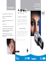
ERLEBEN SIE DINION,
D E N S TA N D A R D F Ü R
I N T E L L I G E N T E Ü B E RWAC H U N G
Die intelligenten Überwachungskameras der
Dinion™-Reihe basieren auf dem einzigartigen
Sachwissen von Philips im Bereich der Funk-,
Fernseh-, Video-, Halbleiter- und Bildverarbeitungstechnik und bieten eine bessere
Bildleistung als jede andere Kamera dieser
Klasse.
Perfektes Bild, selbst bei Gegenlicht
Perfektes Bild, ideal zum Erkennen und Identifizieren
Perfektes Bild, selbst unter schwierigen Beleuchtungsbedingungen
Die Kamerareihe, die um den leistungsstarken
Philips Dinion Videoverarbeitungs- Chip herum
aufgebaut ist, zeichnet sich durch hervorragende Funktionalität, Intelligenz und Bildverbes-
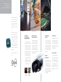
AUSGEZEICHNETE
BILDQUALITÄT FÜR EINE
BESSERE IDENTIFIZIERUNG
NIGHTSENSE™, WENN DIE
SONNE UNTERGEGANGEN IST
IM HANDUMDREHEN
INSTALLIERT!
SIE HABEN DIE WAHL
Welche Anforderungen auch immer Sie auch
serungstechnologie in einem eleganten und
Die hochauflösenden Farbmodelle der Dinion-
Die Installation von Dinion-Kameras ist so
stellen, es gibt immer eine passende Dinion-
dennoch unauffälligen Gehäuse aus. Die
Die ausgezeichnete Bildqualität der Dinion-
Reihe sind mit NightSense ausgestattet. Diese
einfach, dass Ihr normaler Arbeitsablauf nur
Kamera für Sie. Sie haben die Wahl zwischen
Kameras lassen sich sehr schnell installieren –
Kameras beruht auf mehreren Faktoren. Das
Funktion nutzt die höhere Empfindlichkeit von
kürzeste Zeit unterbrochen wird. Es werden
Farb- und Schwarz-/Weiss Ausführungen,
so dass der normale Arbeitsablauf nur kürzeste
revolutionäre
Lens Wizard™ Verfahren
Schwarz-/Weiss Bildern, um die Empfindlichkeit
keinerlei Werkzeuge benötigt und die Kamera
Modellen für Innen- oder für Aussen-
gewährleistet eine perfekte Kompatibilität von
der Kamera um den Faktor 3 anzuheben.
wird betriebsbereit geliefert. Sie braucht nur
anwendungen und Kameras mit normaler
Objektiv und Kamera, so dass unter allen
Wenn das Tageslicht schwächer wird, schaltet
montiert und angeschlossen zu werden ... und
oder mit hoher Auflösung
Bedingungen ein optimales Bild möglich wird.
die Kamera automatisch auf Schwarz-/Weiss
ist anschließend sofort einsatzbereit, um Ihr
Es unterstützt ausserdem die Einstellung des
Betrieb um, damit wird die hervorragende
Objekt zu schützen.
Dinion, der Standard für intelligente Über-
Auflagemasses und garantiert auch bei geringer
Bildqualität aufrecht erhalten.
wachung.
Beleuchtung scharfe Bilder. “Auto Black” sorgt
Zeit unterbrochen wird – und sind unglaublich
einfach zu bedienen.
für einen optimalen Kontrast, auch bei Nebel
oder wenn das Gehäusefenster beschlagen
oder
verschmutzt
ist.
Der
QUALITÄT - GARANTIERT
ATTRAKTIVES
ERSCHEINUNGSBILD
breite
Philips ist einer der weltweit führenden
Hersteller von Sicherheitssystemen. Alle
unsere CCTV- Anlagen und natürlich auch
Dynamikumfang erleichtert die Identifizierung
Wie Sie sehen, wurde die Dinion- Kamera so
die Dinion- Kameras wurden nach den höch-
von Details. Auch die treue Farbwiedergabe
gestaltet, dass Gehäuse und Objektiv nahtlos
sten
trägt zu einer sicheren Erkennung bei.
ineinander überzugehen scheinen, als ob die
gefertigt. Ausserdem bekommen Sie volle
Kamera aus einem Stück besteht und nicht aus
drei Jahre Gewährleistung, ein kostenloses
zwei Teilen zusammengesetzt ist. Diese
Ersatzprogramm
Formgebung und die kompakten Abmes-
Unterstützung von unserem weltweiten
sungen verleihen der Dinion- Kamera ein per-
Service.
fektes Aussehen: unauffällig und gleichzeitig
Gering beleuchteter
Aussenbereich:
Mit einer normalen Kamera
erfasstes Bild
Gering beleuchteter
Aussenbereich:
Erfassung mit
NightSense™
ästhetisch ansprechend.
internationalen
und
Qualitätsstandards
die
kompetente
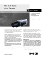
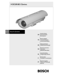
LTC 0435 Series
Color Cameras
•
•
•
•
•
•
•
•
The LTC 0435 series are compact rugged, 1/3-inch image
format digital color CCD cameras. Their superior
sensitivity and resolution provide optimal performance
in virtually all environments.
This fully automatic camera is ready to work for you,
and is easy to install in even the most demanding
applications. On- screen Displays (OSD) provide quick
and easy access to all camera features.
The LTC 0435 cameras also comes with a lens wizard
that automatically detects the type of lens installed and
provides an OSD guide that allows the installer to easily
adjust the lens level and focus without special tools or
filters.
The automatic black level feature, now introduced in
color cameras, enhances contrast by removing veiling
glare from the picture.
The wide range of through the lens automatic sensing
tracking white balance provides true to life color images
for indoor and outdoor applications.
Security you can rely on
1/3-inch Format CCD Imager
High Sensitivity
Advanced Digital Signal
Processing
Standard Resolution
Auto Detection of Lens Type
Easy to Install
Accepts AC or DC Voltages
The ability to operate on AC or DC provides added
flexibility to system designs and reduces the amount of
training and support items to keep on-hand.
Easy Installation, digital signal processing, on screen
displays, superior picture quality and reliability brings the
video performance of standard resolution color cameras
to a level never reached before and makes the LTC 0435
series the best choice for first time and professional users.
Bilinx Technology
The LTC0435 series cameras incorporate Bilinx. Bilinx is
a bi-directional communication capability embedded in
the video signal of all Bosch Dinion cameras. With Bilinx
technicians can check status, change camera settings and
even update firmware from virtually anywhere along the
video cable. Bilinx reduces service and installation time,
provides for more accurate set-up and adjustment, and
improves overall performance. In addition, Bilinx uses
the standard video cable to transmit alarm and status
messages, providing superior performance without
additional installation steps.
SPECIFICATIONS
Controls
Electrical
Video level.
Model No.
Rated Voltage
Voltage Range
System
LTC 0435/10
12 VDC
10.8-39 VDC
24 VAC, 50 Hz
12-28 VAC, 45-65 Hz
LTC 0435/20
12 VDC
10.8-39 VDC
24 VAC, 60 Hz
12-28 VAC, 45-65 Hz
LTC 0435/50
230 VAC, 50 Hz
85-265 VAC, 45-65 Hz
LTC 0435/60
120 VAC, 60 Hz
85-265 VAC, 45-65 Hz NTSC
Shutter: AES/Off/Flickerless
PAL
AGC: On/Off
BLC: On/Off
NTSC
Auto Black: On/Off
ATW: On/Hold
PAL
Power Consumption:
4 W, excluding lens.
Imager:
Interline transfer CCD, 1/3-inch image format.
R-offset
B-offset
Vphase Adjustment: 0 - 358 degrees
Active Picture Elements:
MECHANICAL
Connectors:
PAL Models:
500 H x 582 V.
- Video Output:
NTSC Models:
510 H x 494 V.
- Video/DC-Iris connector: 4-pin EIA-J.
Sensitivity (3200 k):
Scene illumination1)
Imager illumination
BNC.
Power:
Usable Picture Full Video
LTC 0435/10 and LTC 0435/20: push type
(50 IRE)
connectors, polarity independent, isolated
fc
0.039
0.16
from video output terminals
lx
0.39
1.6
LTC 0435/50: 2-wire power cord with Euro plug
fc
0.006
0.024
LTC 0435/60: 2-wire power cord with
lx
0.06
0.24
polarized plug
1) for f/1.2 lens, 89% scene reflectance.
Camera mounting:
Top and Bottom, 1/4-inch 20 UNC.
Horizontal Resolution:
330 TVL.
Lens mounting:
C and CS.
Signal-to-noise Ratio:
50 dB.
Dimensions:
(HxWxD*) 58 x 66 x 122 mm
AGC:
21 dB, (max).
Electronic Shutter:
Aperture Correction:
(2.28 x 2.6 x 4.8 inch). *including connectors.
Weight:
Automatic, 1/50 to 1/125000 sec. (CCIR),
ENVIRONMENTAL
1/60 to 1/150000 sec. (EIA)
Temperature range:
Horizontal and vertical, symmetrical.
Operating:
0.45 kg (0.99 lb).
-20 to 50°C (-4 to 122 °F).
Backlight Compensation: Center window weighting.
Storage:
-25 to 70°C (-13 to 158 °F).
White Balance:
Automatic sensing (2500 - 9000 K).
Operating Humidity:
5% to 93% non-condensing.
Video Output:
Composite video 1.0 Vpp, 75 ohms.
Electromagnetic compatibility:
Synchronization:
Line-Lock:
(When powered by AC only) Synchronizes
EMC immunity:
According EN50130-4
EMC emission:
According EN505022 class B,
the camera to the power line zero crossing
for roll-free vertical interval switching.
According FCC, class B part 15
Safety:
Vertical phase delay can be adjusted
LTC 0435/10 and LTC 0435/50: EN60065
(0 - 358 degrees) to allow vertical
LTC 0435/20 and LTC 0435/60: UL6500
synchronization in multi-phase power
Accessories
installations
Lenses DC-Iris:
Free Running (When DC-supply or L/L off):
LTC 3364/40:
2,8 - 12 mm, F1,4 - F360.
Internal crystal reference is standard on all
LTC 3374/20:
5 - 50 mm, F1,4 - F185.
models.
Power Transformers and Power Supplies:
Model No.
Rated Input
Rated Output
TC1334
120 VAC, 60 Hz
24 VAC, 30 VA
TC120PS
120 VAC, 60 Hz
15 VDC, 9 VA
TC220PSX-24
220 - 240 VAC, 50/60 Hz 24 VAC, 20 VA
TC220PS
220 - 240 VAC, 50/60 Hz 15 VDC, 9 VA
Bosch Security Systems.
5600 JB Eindhoven
The Netherlands
Tel: +31 (40) 27 80000
Fax: +31 (40) 27 80001
www.boschsecuritysystems.com
9922 141 00433en 03-08 | Printed in The Netherlands | November 2003 • Data subject to change without notice.
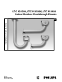
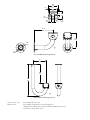
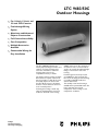
LTC 9215/00, LTC 9215/00S, LTC 9219/01
Indoor/Outdoor Feed-through Mounts
Installation Instructions
Eng
Philips
Communication,
Security & Imaging
SAFETY PRECAUTIONS
3
The exclamation point within an equilateral triangle is
intended to alert the user to presence of important
operating and maintenance (servicing) instructions in
the literature accompanying the appliance.
SECURITE
Le point d'exclamation à l'intérieur d'un triangle
équilatéral avertit l'utilisateur de la présence d'instructions importantes d'utilisation et de maintenance dans
la documentation accompagnant l'appareil.
DESCRIPTION
LTC 9215/00 30-cm (12-in), LTC 9215/00S 18-cm (7-in),
and LTC 9219/01 40-cm (15-in) Feed-through Mounts.
This indoor/outdoor mounting equipment is designed for fixed
camera or camera housing installations up to 9 kg (20 lb) rated
load. These models are made of lightweight aluminum and feature welded construction, providing an extremely rigid camera
mount. The LTC 9215/00S has been designed specifically for
the LTC 9480 series housings, while the LTC 9215/00 and LTC
9219/01 can be used with the LTC 9480, LTC 9483, and LTC
9488 series camera housings. All mounts come fully assembled.
SICHERHEITSVORKENHRUNGEN
Das Ausrufezeichen in dem gleichseitigen Dreieck ist
dazu da, den Benutzer auf wich-tige Inbetriebnahmeund Instandhaltungs-vorschriften hinzuweisen, die
dem Gerät in Form einer Broschüre beigelegt sind.
4
WARNING: All mounts are designed to support a
load only in a vertical direction. Mounts MUST be positioned as shown under SPECIFICATIONS.
PRECAUCIONES DE SEGURIDAD
El símbolo de exclamación dentro de un triángulo
equilátero, se muestra con el objetivo de alertar al
ususario de que instrucciones de operación y mantenimiento importantes acompañan al equipo.
1
2.
UNPACKING
Unpack carefully. This is mechanical equipment and should be
handled with care.
Check for the following items:
■
Verify the unit model number.
■
Instructions for Use.
If an item appears to have been damaged in shipment, replace it
properly in its carton and notify the shipper. If any items are
missing, notify your Philips Communication, Security &
Imaging, Inc. Sales Representative or Customer Service
Representative. The shipping carton is the safest container in
which the unit may be transported. Save it for possible future use.
2
SERVICE
3.
4.
5.
If the unit ever needs repair service, the customer should contact
the nearest Philips Communication, Security & Imaging, Inc.
Service Center for authorization to return and shipping
instructions.
Service Centers
U.S.A. & Canada: 800-366-2283
Mexico & Central America: 52-5-564-2726
Europe & Middle East: 011-32-1-440-0711
South America: 54-11-4956-0837
Asia Pacific Region: 011-65-481-4422
INSTALLATION
1. Determine a secure wall mounting location.
6.
Cautions:
a. For a secure installation, use four 8-mm (5/16-in) diameter fasteners (not included). Use stainless steel or zinc
plated fasteners.
b. If bolts are used, they should extend through the mounting surface and be secured with flat washers, lock washers, and nuts on the opposite side. Each bolt must have
a minimum pull-out strength of 200 kg (450 lb).
c. If studs are used, they should be anchored in concrete or
welded to a steel backer plate. Each stud must have a
minimum pull out strength of 200 kg (450 lb).
d. If the wall mount is attached to wood or to a blind
structure (with no access to the rear), each fastener must
have a minimum pull-out strength of at least 200 kg
(450 lb).
Locate the four holes or stud locations using the flange as a
template (four holes equally spaced on a 69.9-mm (2-3/4-in
bolt circle).
Feed wires through the large hole in the flange or through
the slot on the surface where the camera housing mounts.
Install the mount using bolts or studs at least 8-mm (5/16in) in diameter.
To mount the camera or camera housing:
a. Mount camera with a 1/4-20 bolt and lock washer (not
furnished) in the center hole of the adjustable head.
b. Mount housings with three 1/4-20 bolts and lock
washers (not furnished).
c. Lock mount head in position by using the supplied
1/8-inch long-arm hex wrench to tighten screws.
For additional information or to speak to a representative,
please contact the Philips Communication, Security &
Imaging location nearest you:
The Americas: 1 800 326 3270
Europe & Middle East: 31 40 278 1222
Asia Pacific Region: 65 350 1859
or visit our Web site at www.philipscsi.com.
2
5
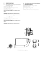
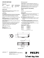
SPECIFICATIONS
5.3
LTC 9219/01 40-cm (15-in) Indoor/Outdoor
Feed-through J-mount
Maximum Load: 9 kg (20 lb).
Mounting Head: Adjustable. 360° pan, 180° tilt.
Finish: Dark mushroom.
Approx. Weight: 0.55 kg (1.2 lb).
5.1
LTC 9215/00 30-cm (12-in) Indoor/Outdoor
Feed-through Mount
Maximum Load: 9 kg (20 lb).
Mounting Head: Adjustable. 360° pan, 180° tilt.
Finish: Dark mushroom.
Approx. Weight: 0.4 kg (0.9 lb).
Accessory for LTC 9215/00: LTC 9213/00 Pole Mount
Adapter.
WARNING: All mounts must be mounted as shown.
WARNING: All mounts must be mounted as shown.
5.2
LTC 9215/00S 18-cm (7-in) Indoor/Outdoor
Feed-through Mount
Maximum Load: 9 kg (20 lb).
Mounting Head: Adjustable. 360° pan, 180° tilt.
Finish: Dark mushroom.
Approx. Weight: 0.3 kg (0.7 lb).
Accessory for LTC 9215/00S: LTC 9213/00 Pole Mount
Adapter.
WARNING: All mounts must be mounted as shown.
88.9
3.50
7.9
0.31
73.2
2.88
37.3
1.47 74.7
2.94
12.7
0.50
23.9
0.94
25.4
1.00
6.9
0.27
306.8
12.08
138.3
5.45
88.9
3.50
mm
in
8.9
0.35
LTC 9215/00 Feed-through Mount
3
88.9
3.50
7.9
0.31
73.2
2.88
37.3
1.47
74.7
2.94
12.7
0.50
25.4
1.00
23.9
0.94
6.9
0.27
179.8
7.08
138.3
5.45
88.9
3.50
mm
in
8.9
0.35
LTC 9215/00S Feed-through Mount
157
6.2
234
9.2
391
15.4
mm
in
LTC 9219/01 Feed-through J-mount
3935 890 15114 01-06
Printed in U.S.A.
© 2001 Philips Electronics N.V.
© 2001 Philips Communication, Security & Imaging, Inc.
All Rights Reserved. Philips ® is a registered trademark of Philips Electronics N.V.
Data subject to change without notice
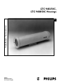
LTC 9483/50C,
LTC 9488/50C Housings
Installation Instructions
Eng
Philips
Communication,
Security & Imaging
2
13. Overloading - Do not overload outlets and extension cords as this can result
in a risk of fire or electric shock.
14. Object and Liquid Entry - Never push objects of any kind into this unit
through openings, as they may touch dangerous voltage points or short out
parts that could result in a fire or electric shock. Never spill liquid of any
kind on the unit.
15. Servicing - Do not attempt to service this unit yourself as opening or
removing covers may expose you to dangerous voltage or other hazards.
Refer all servicing to qualified service personnel.
16. Damage Requiring Service - Unplug the unit from the outlet and refer
servicing to qualified service personnel under the following conditions:
a. When the power supply cord or plug is damaged.
b. If liquid has been spilled or objects have fallen into the unit.
c. If the unit has been exposed to rain or water.
d. If the unit does not operate normally by following the operating
instructions. Adjust only those controls that are covered by the
operating instructions, as an improper adjustment of other controls
may result in damage and will often require extensive work by a
qualified technician to restore the unit to its normal operation.
e. If the unit has been dropped or the cabinet has been damaged.
f. When the unit exhibits a distinct change in performance--this indicates
a need for service.
17. Replacement Parts - When replacement parts are required, be sure the
service technician has used replacement parts specified by the manufacturer
or have the same characteristics as the original part. Unauthorized
substitutions may result in fire, electric shock, or other hazards.
18. Safety Check - Upon completion of any service or repairs to this unit, ask
the service technician to perform safety checks to determine that the unit is
in proper operating condition.
19. Coax Grounding - If an outside cable system is connected to the unit, be
sure the cable system is grounded. U.S.A. models only--Section 810 of the
National Electrical Code, ANSI/NFPA No.70-1981, provides information
with respect to proper grounding of the mount and supporting structure,
grounding of the coax to a discharge unit, size of grounding conductors,
location of discharge unit, connection to grounding electrodes, and
requirements for the grounding electrode.
20. Lightning - For added protection of this unit during a lightning storm, or
when it is left unattended and unused for long periods of time, unplug it
from the wall outlet and disconnect the cable system. This will prevent
damage to the unit due to lightning and power line surges.
IMPORTANT SAFEGUARDS
1.
2.
3.
4.
5.
6.
7.
Read Instructions - All the safety and operating instructions should be read
before the unit is operated.
Retain Instructions - The safety and operating instructions should be
retained for future reference.
Heed Warnings - All warnings on the unit and in the operating instructions
should be adhered to.
Follow Instructions - All operating and use instructions should be followed.
Cleaning - Unplug the unit from the outlet before cleaning. Do not use
liquid cleaners or aerosol cleaners. Use a damp cloth for cleaning.
Attachments - Do not use attachments not recommended by the product
manufacturer as they may cause hazards.
Accessories - Do not place this unit on an unstable stand, tripod, bracket,
or mount. The unit may fall, causing serious injury to a person and serious
damage to the unit. Use only with a stand, tripod, bracket, or mount
recommended by the manufacturer or sold with the product. Any
mounting of the unit should follow the manufacturer's instructions and
should use a mounting accessory recommended by the manufacturer.
An appliance and cart combination should be moved with care. Quick
stops, excessive force, and uneven surfaces may cause the appliance and cart
combination to overturn.
8. Ventilation - Openings in the enclosure, if any, are provided for ventilation,
to ensure reliable operation of the unit, and to protect it from overheating.
These openings must not be blocked or covered. This unit should not be
placed in a built-in installation unless proper ventilation is provided or the
manufacturer's instructions have been adhered to.
9. Power Sources - This unit should be operated only from the type of power
source indicated on the marking label. If you are not sure of the type of
power supply you plan to use, consult your appliance dealer or local power
company. For units intended to operate from battery power or other
sources, refer to the operating instructions.
10. Grounding or Polarization - This unit may be equipped with a polarized
alternating-current line plug (a plug having one blade wider than the other).
This plug will fit into the power outlet only one way. This is a safety
feature. If you are unable to insert the plug fully into the outlet, try
reversing the plug. If the plug should still fail to fit, contact your electrician
to replace your obsolete outlet. Do not defeat the safety purpose of the
polarized plug.
Alternately, this unit may be equipped with a 3-wire grounding-type plug, a
plug having a third (grounding) pin. This plug will only fit into a
grounding-type power outlet. This is a safety feature. If you are unable to
insert the plug into the outlet, contact your electrician to replace your
obsolete outlet. Do not defeat the safety purpose of the grounding-type
plug.
11. Power Cord Protection - Power supply cords should be routed so that they
are not likely to be walked on or pinched by items placed upon or against
them, paying particular attention to cords and plugs, convenience
receptacles, and the point where they exit from the appliance.
12. Power Lines - An outdoor system should not be located in the vicinity of
overhead power lines or other electric light or power circuits or where it can
fall into such power lines or circuits. When installing an outdoor system,
extreme care should be taken to keep from touching such power lines or
circuits as contact with them might be fatal. U.S.A. models only - refer to the
National Electrical Code Article 820 regarding installation of CATV systems.
For additional information or to speak to a representative,
please contact the Philips Communication, Security & Imaging
location nearest you:
The Americas: 1 800 326 3270
Europe & Middle East: 31 40 278 1222
Asia Pacific Region: 65 350 1859
or visit our Web site at www.philipscsi.com.
3
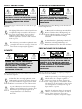
SAFETY PRECAUTIONS
SICHERHEITSVORKEHRUNGEN
VORSICHT: UM EINEN ELEKTRISCHEN
SCHLAG ZU VERMEIDEN, ABDECKUNG
NICHT ENTFERNEN. WARTUNGEN ALLER
ART QUALIFIZIERTEM PERSONAL
ÜBERLASSEN.
CAUTION: TO REDUCE THE RISK OF
ELECTRICAL SHOCK, DO NOT OPEN COVERS.
NO USER SERVICEABLE PARTS INSIDE. REFER
SERVICING TO QUALIFIED SERVICE
PERSONNEL.
This label may appear on the bottom of the unit due to space
limitations.
Aus Platzgründen kann diese Warnung auf der Unterseite des
Gerätes angebracht sein.
The lightning flash with an arrowhead symbol within
an equilateral triangle is intended to alert the user to
the presence of uninsulated "dangerous voltage"
within the product's enclosure that may be of
sufficient magnitude to constitute a risk of electric
shock to persons.
Das Blitzsymbol im gleichseitigen Dreieck soll den
Benutzer auf nicht isolierte "Hochspannung" im
Gehäuse aufmerksam machen, die eventuell stark
genug ist, um einen elektrischen Schlag zu
verursachen.
Das Ausrufezeichen im gleichseitigen Dreieck soll
den Benutzer auf wichtige Bedienungs- und
Wartungsanleitungen in der dem Gerät beigefügten
Literatur aufmerksam machen.
The exclamation point within an equilateral triangle
is intended to alert the user to presence of important
operating and maintenance (servicing) instructions
in the literature accompanying the appliance.
PRECAUCIONES DE SEGURIDAD
SECURITE
PRECAUCION: PARA REDUCIR EL RIESGO DE
CHOQUE ELÉCTRICO, FAVOR NO ABRIR LA
CUBIERTA. ESTE EQUIPO NO CONSTA DE
PIEZAS O PARTES QUE REQUIEREN SERVICIO
O MANTENIMIENTO. PARA REPARACIONES
FAVOR REFERIRSE A UN TÉCNICO
CALIFICADO.
DANGER: POUR ÉVITER TOUT RISQUE
D'ÉLECTROCUTION, NE PAS OUVRIR LE
BOÎTIER. IL N'Y A PAS DE PIÈCES
REMPLAÇABLES À L'INTÉRIEUR. POUR
TOUTE RÉVISION, S'ADRESSER À UN
TECHNICIEN SPÉCIALISÉ.
Debido a limitaciones de espacio, esta etiqueta puede aparecer
en la parte inferior de la unidad.
En raison de limitation de place, cette étiquette peut être placée
sur le dessous de l'appareil.
El símbolo representado por un relámpago con punta
de flecha dentro de un triángulo equilátero, se
muestra con el objetivo de alertar al usuario que
existen "voltages peligrosos" sin aislamiento, dentro
de la cubierta de la unidad. Dichos voltages pueden
ser de tal magnitud que constituyen un riesgo de
choque eléctrico a personas.
L'éclair fléché dans un triangle équilatéral, avertit
l'utilisateur de la présence d'une "tension dangereuse"
non isolée à l'intérieur de l'appareil et d'une valeur
suffisante pour constituer un risque d'électrocution.
Le point d'exclamation contenu dans un triangle
équilatéral, avertit l'utilisateur de la présence, dans la
documentation qui accompagne l'appareil, de
consignes d'utilisation et de maintenance
importantes.
El símbolo de exclamación dentro de un triángulo
equilátero, se muestra con el objetivo de alertar al
ususario de que instrucciones de operación y
mantenimiento importantes acompañan al equipo.
4
CONTENTS
2
1
2
2.1
2.2
3
4
5
6
6.1
6.2
6.3
6.4
6.5
6.6
6.7
6.8
6.8.1
2.1 Sunshields
Provide protection from the direct rays of sun and promote
cooling to reduce internal housing temperatures. Strongly
recommended for housing to be used outdoors.
UNPACKING . . . . . . . . . . . . . . . . . . . . . . . . . . .5
ACCESSORIES . . . . . . . . . . . . . . . . . . . . . . . . . .5
Sunshields . . . . . . . . . . . . . . . . . . . . . . . . . . . . . . .5
Tamperproof Kit . . . . . . . . . . . . . . . . . . . . . . . . . .5
SERVICE . . . . . . . . . . . . . . . . . . . . . . . . . . . . . . .5
CARE AND MAINTENANCE . . . . . . . . . . . . . . .5
DESCRIPTION . . . . . . . . . . . . . . . . . . . . . . . . . .5
INSTALLATION . . . . . . . . . . . . . . . . . . . . . . . . .5
Model Designation . . . . . . . . . . . . . . . . . . . . . . . .5
Maximum Camera/Lens Size . . . . . . . . . . . . . . . . .5
Tools Required . . . . . . . . . . . . . . . . . . . . . . . . . . .5
Cable Requirements . . . . . . . . . . . . . . . . . . . . . . . .5
Housing Mounting . . . . . . . . . . . . . . . . . . . . . . . .6
Cover Removal . . . . . . . . . . . . . . . . . . . . . . . . . . .6
Camera/Lens Installation . . . . . . . . . . . . . . . . . . . .6
Camera/Lens Wiring . . . . . . . . . . . . . . . . . . . . . . .8
Power Connections:
LTC 9483/50C, LTC 9488/50C . . . . . . . . . . . . .8
6.8.2 Control Connections: LTC 9488/50C Only . . . . . .9
6.9
Video Coax Connection . . . . . . . . . . . . . . . . . . . . .9
6.10 Camera/Lens Adjustment . . . . . . . . . . . . . . . . . . . .9
6.11 Final Assembly . . . . . . . . . . . . . . . . . . . . . . . . . . . .9
6.12 Fuse Replacement . . . . . . . . . . . . . . . . . . . . . . . .10
7
EXPLODED VIEW . . . . . . . . . . . . . . . . . . . . . .10
7.1
Parts List . . . . . . . . . . . . . . . . . . . . . . . . . . . . . . .10
LTC 9083/00: For LTC 9483 Series Housings.
LTC 9088/00: For LTC 9488 Series Housings.
2.2
Tamperproof Kit
Contains tamper resistant screws and bit key to tamperproof up
to five housings.
LTC 9080/00: For all LTC 9480 Series Housings.
3
SERVICE
If the unit ever needs repair service or parts, the customer
should contact Philips Communication, Security & Imaging
Service Center for authorization to return and shipping
instructions.
4
CARE AND MAINTENANCE
Regularly scheduled maintenance will help prolong the
operation life of this unit. Clean the viewing window as needed
with a mild, nonabrasive detergent in water and a soft cloth.
5
1
ACCESSORIES
DESCRIPTION
The LTC 948x Series Housings are smart, stylized housings for
indoor and outdoor use. These housings meet customers'
demands for an attractive housing that is both cost competitive
and easy to install. They are available in three sizes to fit a wide
range of cameras and lenses.
UNPACKING
Unpack carefully. This is mechanical equipment and should be
handled with care.
Check for the following:
■
Housing (with correct model number).
■
Hardware Kit - LTC 9483/50C & LTC 9488/50C:
1 1/4-20 × 3/8-in button head screw.
2 1/4-20 × 1/2-in button head screw.
1 Connector plug, 4-pin female Amphenol 16T3109-001.
1 Connector, 15-pin female Ampenol C016 10e0140021
(LTC 9488/50C only).
9 Female socket pins (LTC 9488/50C only).
2 1/4-in spring washers.
1 Spacer block.
2 2.0 × 10 mm screws.
6
INSTALLATION
This installation should be made by qualified service personnel
and conform to the National Electrical Code and applicable
local codes.
6.1
Model
No.
Model Designation
Voltage/
Power
V/W
LTC 9483/50C Heater
230/23
LTC 9488/50C Heater
230/40
Note: The heater operates at 50/60 Hz.
6.2
Preinstalled
Heater
Use with Camera
Models with These
Voltage Ratings
230
230
Maximum Camera/Lens Size
LTC 9483/50C: 68 W x 54 H x 267 L mm (2.68 x 2.1 x 10.5 in)
LTC 9488/50C: 71 W x 71 H x 356 L mm (2.8 x 2.8 x 14.0 in)
If an item appears to have been damaged in shipment, replace it
properly in its carton and notify the shipper. If any items are
missing, notify your Philips Communication, Security &
Imaging Sales Representative or Customer Service Representive.
6.3 Tools Required
- Small flat blade screwdriver.
- Phillips screwdriver (P2).
- Adjustable wrench.
- Wire cutter/stripper/crimper tool.
- 5/32-in (or 4 mm) hex wrench.
The shipping carton is the safest container in which the unit
may be transported. Save it for possible future use.
6.4 Cable Requirements
Video Transmission (Coaxial)
Cable Type:
RG-59/U for runs < 300 m (1000 ft).
RG-11/U for runs < 600 m (2000 ft).
5
Cable Size:
Outside diameter between
4.6 mm (0.181-in) - 7.9 mm (0.312-in).
Cable Shape:
Round.
Shield:
> 93% Braided Copper Shield.
Center Conductor: Stranded Copper Center.
DC Resistance:
< 15 Ohms/1000 (RG-59/U).
< 6 Ohms/1000 (RG-11/U).
Cable Impedence: 75 Ohm.
Agency Rating:
UL, CE.
Environmental:
Outdoor rated.
Temperature Rating: > 80 °C.
Sources:
Belden 9259.
Belden 9238.
6.5 Housing Mounting
1. Use the two 1/4-20 x 0.50-inch screws and 1/4-in spring
washers provided in the hardware kit to mount the housing
to a mount or a pan/tilt. The spring washers must be used
for the screws to thread properly.
2. The outer most set of 1/4-20 threaded holes are for
mounting to feed-through mounts and the inner most 1/420 holes are for mounting to all other mounts and pan/tilts.
6.6 Cover Removal
1. Loosen the top two screws on the rear of the housing. These
screws are captive and will not come out all the way. Do not
remove the bottom two screws. See Figure 1.
Input Power Cord - North American
Cable Type:
SJTOW-A rated.
Cable Size:
Outside diameter between
4.3 mm (0.170 in) - 11.9 mm (0.470 in).
Cable Shape:
Round.
Conductors:
3 conductor version and
2 conductor version.
Agency Rating:
UL/C.S.A., UL VW-1.
Environmental:
Outdoor rated.
Temperature Rating: 105 °C.
Voltage Rating:
300 V.
Sources:
Belden 19506.
Belden 19509.
Northwire 573939.
Loosen these screws
Do not remove
Input Power Cord - European
Cable Type:
H05RN-F3G0.75 and
H05RN-F3G1.00.
Cable Size:
Outside diameter between
9.5 mm (0.374 in) –13 mm (0.512 in).
Cable Shape:
Round.
Conductors:
3 conductor version and
2 conductor version.
Agency Rating:
VDE.
Environmental:
Outdoor rated.
Sources:
Olflex 1600252.
Olflex 1600253.
Figure 1: Loosening Captive Screws
2. Grasp the housing's front cap and pull forward. Do not
squeeze the cover itself. This will make it difficult to slide off
the cover. See Figure 2.
Lens Control Cable
Cable Type:
Jacketed Multiconductor Cable.
Cable Size:
Outside diameter between
11 mm (0.433 in)–13 mm (0.512 in).
Cable Shape:
Round.
Shield:
Overall shielding.
Conductors:
35 to 24 AWG.
No. of Conductors: 14 total, 8 used.
Conductor
Insulation:
Color coded.
Sources:
Amphenol-Tuchel: 14-pin +PE.
Figure 2: Removing the Cover
3. The cover is attached to the base. Allow the cover to dangle
from the base.
6.7 Camera/Lens Installation
1. Loosen the two screws holding the camera bracket to the
base. It is not necessary to remove them completely. See
Figure 3.
6
Mounting LTC 0330/x1, LTC 0350/x1, LTC 0430/x1, and
LTC 0450/x1 fixed lens cameras in LTC 9480, LTC 9483
Series Housings
3c. Remove the mounting block from the camera by removing
the two small screws that attach the foot to the camera. Use
a small straight blade screw driver to remove these screws.
See Figure 5.
Camera
Camera
Bracket
Loosen These Screws
Camera
Foot
Figure 3: Removing the Camera Bracket
2. Remove the camera bracket from the base.
Camera Screws
Mounting fixed lens cameras in LTC 9483 Series
Housings
3a. Attach the lens to the camera.
Figure 5: Removing the Camera Foot
3d. Attach the lens to the camera.
3b. Use the 1/4-20 x 3/8-inch screw to mount the camera to the
camera bracket. The lens should extend approximately 6
mm (0.25-in) from the front of the camera bracket. See
Figure 4.
3e. Mount the camera to the camera bracket using the two
screws removed from the foot. Use the slots in the camera
bracket to accomplish this. See Figure 6.
Note: The hardware kit contains a spacer block. This spacer
block can be used to raise the camera off the camera bracket.
Simply place the spacer block between the camera and the
camera bracket and through the screws. This is only necessary in
very few instances when the lens may hit the camera bracket.
Camera
Camera
Bracket
1/4-20 × 3/8 Screw
6.4 mm
0.25 in
Figure 4: Attaching the Camera
Figure 6: Mounting the Camera
7
6.8
Video
BNC Jack
Camera/Lens Wiring
WARNING: Only use the cables specified under
"INSTALLATION, Cable Requirements" for wiring
of all cameras and lenses.
6.8.1
Power Connections: LTC 9483/50C,
LTC 9488/50C
1. Cut the camera power cord, leaving enough cable to allow
connection to the terminal block. Strip no less than 6 mm
(0.25 in) and no more than 8 mm (0.31 in) of insulation
away from the wire. Connect these wires to the left side or
the top side of the terminal block. See Figure 7.
Power
Connector
Electrical Connections: LTC 9483/50C
Camera
Neutral
Wire
Control
Connector
Power
Connector
Camera
Line
Wire
Video BNC
Jack
Electrical and Control Connections: LTC 9488/50C
Figure 8: Electrical Connections
4. Connect power input cable to the provided connector plug.
Refer to wiring diagrams for pin connections. The following
table corresponds to Figure 9: Power Connector.
Figure 7: Camera Power Connection
2. The terminal block provided on /X0 units accepts wire
ranging from 20 to 14 AWG or 1.5 mm2. When using larger
wire sizes, splice to a smaller wire at the terminal block end.
230 Vac, 50 Hz Enclosures
Pin
1
2
3
4
3. All electrical connections are made through the power
connector. See Figure 8.
Function
AC Neutral
AC Hotl
NC2t2
Ground
Color1
Blue
Brown
-Green/Yellow
1. Color codes indicate harness wire color.
2. NC - No connection, Do Not Use.
8
The following table refers to Figure 10.
LTC 9488/50C only:
2
3
1
G
Pin
4
5
6
7
8
9
10
11
12
13
14
Function
Zoom Wipeer
Pot Return
NC2
Focus, Wiper
Pot Supply
NC
Focus - Far
Focus - Near
NC
Zoom - Wide
Zoom - Tele
Color1
Pink
Gray
-Light Blue
Orange
-Blue
White
-Green
Red
1. Color codes indicate harness wire color.
2. NC - No connection, Do Not Use.
6.9
Figure 9 Power Connector
Video Coax Connection
WARNING: Only use the cables specified under
"INSTALLATION, Cable Requirements" for wiring
of the video coax connection.
1. A video connection is provided on the rear of the housing.
Connect video cable to housing using a BNC connector.
Mating Connector: Amphenol-Tuchel
16T3109001 (Female) Philips #3152525-900.
2. An internal video connection is provided. Simply connect
the BNC cable to the camera.
6.8.2 Control Connections: LTC 9488/50C only
1. Inside housing, mate lens connector to female connector
located inside of housing. Internal connector is prewired to
the external 14-pin Amphenol Connector.
6.10 Camera/Lens Adjustment
1. Verify camera and lens operation before final assembly of
the cradle into the housing. Adjust the camera focus and
iris as necessary. See individual camera instructions.
2. External Wiring: Control wires 35 to 24 AWG should be
used. Strip 2.5–3 mm of insulation away from wire. Next,
insert each stripped wire into provided socket and crimp to
secure wire.
6.11 Final Assembly
1. Reinstall the cover. Align the bottom of the cover ribs with
the top of the base. Slide the cover onto the base. Make sure
the seal is not folded over or torn. Use silicone grease to
lubricate the seals if necessary. See Figure 11.
3. Insert pin sockets into the black receptacles located on the
provided female connector (see the following below for
correct wiring configuration) and mate to the male
connector located on the back of the housing (see Figure 8).
Then, utilize supplied parts to protect wires.
Figure 11: Reinstalling the Cover
2. As the cover nears the rear cap, make sure the captive screws
in the back are not blocking the cover from engaging into
the rear cap.
Figure 10 Control Connector
Mating Connector: Amphenol-Tuchel
C016 10E014 0021 Philips #3153502-900.
3. Screw the two rear captive screws into the housing.
9
6.12 Fuse Replacement
1. To replace a fuse, take a flat blade screw driver and twist the
top of the fuseholder counter clockwise about a ⁄ of a turn.
The fuse is spring loaded so it will eject.
2. Replace the fuse with a fuse that has the same current rating.
The fuse is a 5x20 mm slow blow cartridge type fuse.
Recommend using Littelfuse series 218.
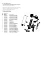
7 EXPLODED VIEW
7.1
Parts List
Ref
No.
1
1
1
1
1
1
2
2
3
4
4
4
5
6
6
7
7
7
8
8
8
9
9
6
6
-
Drawing
Number
315 3369 020
315 3369 050
315 3369 060
315 3368 020
315 3368 050
315 3368 060
315 3142 001
315 3142 002
315 3143 001
315 3144 020
315 3144 050
315 3144 060
315 3145 001
315 3146 001
315 3146 003
315 3147 001
315 3147 002
315 3147 003
315 3148 001
315 3148 002
315 3148 003
315 3149 001
315 3149 003
315 3062 001
315 3062 003
315 3046 004
315 3062 004
315 3046 005
315 3062 006
Part Description
24 VAC Heater Kit (LTC 9483)
230 VAC Heater Kit (LTC 9483)
115 VAC Heater Kit (LTC 9483)
24 VAC Heater Kit (LTC 9488)
230 VAC Heater Kit (LTC 9488)
115 VAC Heater Kit (LTC 9488)
Camera Bracket Kit (LTC 9483)
Camera Bracket Kit (LTC 9488)
Foot Kit
24 VAC Fan Kit
230 VAC Fan Kit
115 VAC Fan Kit
Wiring Bracket Kit
Rearcap Kit for LTC 9483 Models
Rearcap Kit for LTC 9488 Models
Base Kit for LTC 9480/00
Base Kit for LTC 9483 Models
Base Kit for LTC 9488 Models
Cover Kit for LTC 9480/00
Cover Kit for LTC 9483 Models
Cover Kit for LTC 9488 Models
Frontcap Kit for LTC 9483 Models
Frontcap Kit for LTC 9488 Models
Hardware Kit for LTC 9483 Models
Hardware Kit for LTC 9488 Models
Recap Kit for LTC 9483/50C Models
Hardware Kit for LTC 9483/50C Models
RearCap for LTC 9488/50C
Hardware Kit for LTC 9488/50C
4
6
5
8
1
3
7
9
2
10
11
3935 890 23113 01-06
Printed In U.S.A.
2001 Philips Electronics N.V.
2001 Philips Communication, Security & Imaging, Inc.
All Rights Reserved. Philips is a registered trademark of
Philips Electronics N.V.
Data subject to change without notice
LTC 9483/50C
Outdoor Housings
n
For 1/4-inch, 1/3-inch, and
1/2-inch CCD Cameras
n
Feed-through Wiring
Option
n
Aluminum and Advanced
Polymer Construction
n
Full Camera Accessibility
n
Cost Competitive
n
Multiple Accessories
Available
n
Connectable Wiring for
Easy Installation
The LTC 9483/50C Housings are
smartly styled housings for indoor and
outdoor use.These housings meet
customers' demands for attractive
housings that are both cost
competitive and easy to install.
The design of these housings is unique.
Removal of two captive screws is all
that is necessary to slide off the cover
and totally expose the camera and
lens.This allows access to all camera
and lens controls when the camera is
in its mounted position.
Powering this housing is made easy
using the 4-pin Amphenol connector
located on the back of the housing.
Philips
Communication,
Security & Imaging
A BNC connector is also mounted on
the back for video connection.Wires
can also be routed through liquid tight
fittings on the bottom rear of the
housing.
Feed-through mounts and J-mounts
are available for these housings.The
base of the housings permits mounting
to pan/tilts, adjustable heads, and
various wall mounts.
This sturdily constructed housing is
available with a preinstalled heater.The
heater maintains the internal
temperature of the housing in cold
temperature conditions.
SPECIFICATIONS
Environmental
Temperature: At external temperature of -40 °C to
+50 °C (-40 °F to +122 °F) maintains internal temperatures
between -20 °C and +55 °C (-4 °F to +131°F) with heater.
Salt Atmosphere: MIL-STD-810E, Method 509, Procedure 1.
Enclosure Protection: Designed to NEMA-3R, IP55.
Electrical
Model
No.
Preinstalled
Heater1
LTC 9483/50C
Heater
Voltage/
Power
V/W
230/23
Use with Camera
Models with These
Voltage Ratings
230
1.The heater operates at 50/60 Hz.
Electromagnetic Compatibility
Mechanical
Safety:
UL, cUL
Designed to meet CE requirements.
Maximum Camera and Lens: LTC 9483/50C: 68 W x
54 H x 267 L mm (2.68 x 2.1 x 10.5 in)1.
1. With heater.
Accessories
Cable Entry:
LTC 9483/50C: 4-pin Amphenol-Yuchel connector accepts
cable diameters 8.0 mm to 9.5 mm (0.31 in to 0.38 in).Two
bottom feed-through liquid tight fittings accept cable
diameters from 4.6 mm to 7.9 mm (0.18 in to 0.31 in).
Window: 3 mm (0.12 in) thick UV-stabilized polycarbonate.
Housing Mounting: Four (4) available 1/4-20 tapped
holes. Only one set of two are required for mounting.
Camera Mounting: Removable camera bracket. Mounted
with two screws.
Construction: Aluminum cover, aluminum base, aluminum
mounting foot, polycarbonate faceplate, glass reinforced
polycarbonate end caps, neoprene gasket, ethylene
propylene seal, and all stainless steel hardware.
Finish: Dark mushroom.
Dimensions: See drawing.
Weight: (approx.)
LTC 9483 Series: 1.8 kg (4 lb).
Sunshield: Provides protection from the direct rays of sun
and promotes cooling to reduce internal housing
temperatures. Strongly recommended for housing to be
used outdoors.
LTC 9083/00: For LTC 9483 Series housings.
LTC 9080/00 Tamper Resistant Kit: Includes 10 screws
and insertion tool to permit tamper resistance for five
housings.
LTC 9215/00 Feed-through Mount: Attached to the
foot of the housings allows wires to be fed-through the
mount and into the foot of the housing.
LTC 9219/01 Feed-through J-Mount: Allows housing to
be mounted from ceiling.
Suggested Applications:
Camera Model
LTC 0140
LTC 0240
LTC 03301
LTC 03501
LTC 04301
LTC 04501
LTC 9483 Lens
Fixed/Vari-focal
Fixed/Vari-focal
Fixed/Vari-focal
Fixed/Vari-focal
Fixed/Vari-focal
Fixed/Vari-focal
1. The camera mounting block must be removed.
404
15.9
107
4.2
96
3.8
259
50.8 10.2
2.0
20
0.8
8
0.3
73.7
2.9
89
3.5
LTC 9483 Series
9498 961 36711 00-09
Printed In U.S.A.
Ó 2000 Philips Electronics N.V.
Ó 2000 Philips Communication, Security & Imaging, Inc.
All Rights Reserved. Philips Ò is a registered trademark of
Philips Electronics N.V.
Data subject to change without notice
mm
in