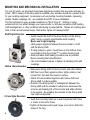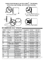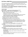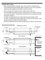
1
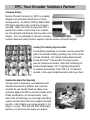
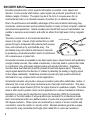
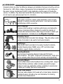
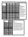
Installation and Wiring Guide
8
Precision Products For Every Application
EPC World Headquarters
Americas Division
464276 Highway 95 South
P.O. Box 249
Sagle, ID 83860-0249 USA
Phone: 800-366-5412
208-263-8541
Fax:
208-263-0541
E-mail: [email protected]
Website: www.encoder.com
EPC- Your Encoder Solutions Partner
Company History
Encoder Products Company Inc. (EPC) is a leading
designer and world-wide manufacturer of motion
sensing devices. Founded in 1969 by William Watt,
EPC began operations with a small line of custom
encoders. Today, more than 40 years later, EPC’s
popular Accu-CoderTM brand is the most complete
line of incremental and absolute shaft encoders in the
industry. Our core philosophy is that each and every
customer deserves quality products, superior customer service, and expert support.
Leading The Industry By Innovation
Concentrating specifically on encoders, we have paved the
path of the encoder industry, providing many of the current
encoder standards. Our industry leading advancements
include the CubeTM style encoder, flex-mount system
used on hollow-bore encoders, Opto-ASIC technology for
enhanced signal quality, 120 C operating temperature
for extreme environments, 6000 CPR in a 1.5" diameter
encoder, a three year standard warranty, and many others.
O
Custom Encoders Our Specialty
Through years of experience, we understand each
industrial environment is different, and customize
encoders for your specific situations. Many of our
customers depend on EPC to provide encoders which
fit their specifications, not someone else's. Using
state of the art technology, we can design and deliver
custom encoders faster than most suppliers standard
products - often shipping your unique encoder in 2 to
6 days, or sooner. Plus, with ISO 9001:2008 quality
systems, you will receive the quality you deserve.
Table of Contents
Warranty Information........................................................................... .1
Encoder Basics................................................................................... .2
Accessories......................................................................................... .3
Mounting and Mechanical Installation.................................................. 4
Recommended Bolt Torques................................................................ 5
Electrical Connection............................................................................ 6
Output Circuit Diagrams....................................................................... 8
Incremental Encoder Wiring Tables..................................................... 9
Absolute Encoder Wiring Tables..........................................................12
Troubleshooting....................................................................................13
Congratulations on your purchase of a genuine EPC Accu-CoderTM brand encoder. Every
Accu-CoderTM is built to exact standards, and thoroughly tested during the manufacturing
process. Improper installation is the major cause of most common problems. By following
the guidelines given in this pamphlet, we hope to eliminate any problems before they start,
thus providing the maximum life from your encoder. Properly installed and cared for, your
Accu-CoderTM will give you years of trouble free use. Technical Bulletins, which provide
general encoder information, and cover specific installations, can be found under the
“Support” heading on www.encoder.com. If you have any questions concerning
installation, please feel free to call Customer Service @ 1-800-366-5412. Thank you!
WARRANTY INFORMATION
Your Accu-CoderTM is guaranteed against defects in materials, and workmanship by the
best three year standard warranty in the business. The warranty applies to all standard
catalog products starting three years from the date of shipment. To learn more about our
three year standard warranty, go to www.encoder.com, under the “Support” menu, select
“Warranty.”
1
ENCODER BASICS
Encoders provide motion control systems information on position, count, speed, and
direction. As the encoder shaft rotates, output signals are produced, proportional to the
distance (angle) of rotation. The signal may be in the form of a square wave (for an
incremental encoder) or an absolute measure of position (for an absolute encoder).
Due to the performance and reliability advantages of the semi-conductor technology they
incorporate, optical encoders are the preferred solution in many common computer, industrial,
and automotive applications. Optical encoders also benefit from ease of customization, are
suitable to numerous environments, and suffer no effects from high levels of stray magnetic
fields.
The basic construction of an incremental encoder is
shown to the right. A beam of light emitted from an LED
passes through a transparent disk patterned with opaque
lines, and is picked up by a photodiode array. The
photodiode array (also called a photosensor) responds
by producing a sinusoidal waveform which is transformed
into a square wave, or pulse train.
PHOTO SENSOR
SQUARING
CIRCUIT
DISK
LED
Incremental encoders are available in two basic output types, single channel and quadrature.
A single channel encoder, often called a tachometer, is normally used in systems that rotate
in one direction only, and require simple position and velocity information. Quadrature
encoders have dual channels (A and B), phased 90 electrical degrees apart. These two
output signals determine the direction or rotation by detecting the leading or lagging signal
in their phase relationship. Quadrature encoders provide very high speed bi-directional
information for very complex motion control applications.
Incremental encoders can provide a once-per-revolution pulse (often called index, marker, or
reference) that occurs at the same mechanical point of encoder shaft revolution. This pulse
is on a separate output channel (Z) from the signal channel or quadrature outputs. The index
pulse is often used to position motion control applications to a known mechanical reference.
Resolution is a term used to describe the Cycles Per Revolution (CPR) for incremental
encoders, or the total number of unique positions per revolution for an absolute encoder.
Each incremental encoder has a defined number of cycles that are generated for each full
360 degree revolution. These cycles are monitored by a counter or motion controller and
converted to counts for position or velocity control. Absolute encoders generate a unique
code word for every resolvable shaft angle (often called bits or counts per revolution).
2
ACCESSORIES
Accessory items are often the difference between an installation that goes smoothly, and one
that does not. EPC offers a range of accessories that are designed to not only make your
life easier, but are manufactured to EPC’s high standards, ensuring years of trouble free
service. In addition, they have been tested with the products they complement, so that you
do not have to worry about proper form, fit, or function.
Connectors/Cables
High quality connectors, cables, cable assemblies, and cord sets
selected to optimize encoder performance; most can be ordered
with MS style or M12 connectors.
Shaft Couplings
Precision shaft couplings to optimize performance and reduce the
chance of premature failure; designed to restrict the transfer of
thermal and mechanical stress; wide range of choices to match your
exact requirement. Call about our new Magnetic Coupling!
Protective Covers
Covers help protect encoders from damage. They also allow a wider
variety of encoders to be used in harsh environments.
Hub/Flanges
Allow Accu-CoderTM encoders to be easily mounted to industry
standard housing styles; NEMA, servo, 5PY, and other styles
available; rugged, reliable construction.
Mounting Brackets
Used to mount measuring wheels to Cube and 702 Series
Accu‑CodersTM. Two types: single pivot and dual pivot; single pivot
pivots vertically while dual pivot pivots vertically and longitudinally.
Measuring Wheels
Used to obtain linear motion feedback from a rotating shaft; range of
surface finishes (urethane, rubber, knurled, grooved) for proper
mating to nearly any application surface; available in several sizes
to allow you to satisfy your exact requirements.
Linear Cable Adapter
The linear cable adapter (LCA) used with a Cube Series standard or
industrial housing, provides a low cost alternative for obtaining
accurate linear measurement.
3
MOUNTING AND MECHANICAL INSTALLATION
For over 40 years, our engineers have been designing encoders that are quick and easy to
install. With a variety of mounting options available, your encoder should be a perfect match
for your existing equipment. Accessories such as pivoting mounting brackets, measuring
wheels, flexible couplings, etc., are available from EPC to ease installation.
The first principle for every encoder installation is "Don't force it!". Striking or using
excessive force can either damage your new encoder, or introduce excessive shaft loading,
shaft misalignment, or other conditions shortening its expected life. Tighten all couplings and
bolts to their recommended torque. Remember, tighter isn't always better!
Shaft Style Encoders
Hollow Bore Encoders
• Gently couple the shaft of the Accu-CoderTM to the driving shaft, using a correctly sized flexible shaft coupling.
Never use a rigid coupling.
• Verify proper alignment between the Accu-CoderTM shaft
and the driving shaft.
• If using pulleys or gears, mount them on the shaft as close
as possible to the Accu-CoderTM to reduce bearing load.
• Axial and radial shaft loading should be low as possible. Never exceed printed specifications.
• Use recommended torques to tighten all clamping bolts and couplings.
C-Face Style Encoders
4
• Make sure driving shaft is free from burrs and other defects.
• With flex mount flush against surface, tighten clamp or set screws first, then bolt flex mount to surface.
• Check for best possible alignment with hollow shaft and
driving shaft to reduce wobble.
• Runout of the driving shaft, or misalignment between the
driving shaft and the encoder’s hollow bore, decreases the accuracy and bearing life of the encoder and adds vibration
to the system. Re-installing the encoder on the driving shaft
may improve alignment.
• Verify that mounting holes are in exact alignment with holes or studs on the motor frame.
• Tighten all fasteners with equal torque so as not to distort the shape of the ring.
Caution: Avoid damage to your Accu-CoderTM . The following
actions may cause damage, and void product warranty.
Do not shock or strike.
Do not disassemble.
Do not subject shaft to excessive
axial or radial shaft stresses.
Do not use a rigid coupling.
RECOMMENDED BOLT TORQUES
MODEL
15T/H
25T/H
225
260, 960
STYLE
All
Clamp
All
Clamp
Flex Hollow
702
Flex Hollow
Flex Hollow
755
Flex Hollow
Collet
770
1.0” up to 1.375”
771
>1.375” to 1.875”
Collet
775
Clamp
Clamp
776
770, 775, 776 All
771
All
All
TR1, TR2
All
TR1
All
All
TR2
All
TR3
All
DESC./LOCATION
Set Screws / Shaft
Clamp Bolt
Set Screws / Shaft
Clamp Bolt
Set Screws / Shaft
Clamp Bolt / Shaft
Set Screws / Shaft
Set Screws / 0.75” Shaft
Cup / Cone Bolts
Clamp Bolt
Clamp Bolt
Cup / Cone Bolts
Clamp Bolt
Clamp Bolt
Protective Cover
Protective Cover
Pivot Bolt/Shaft
Set Screw/Torque Adj
Set Screw/Wheel
Set Screw/Pinion
Set Screw/Wheel
Spring Pivot Clamp
THREAD
M3
6-32
6-32
2-56
6-32
4-40
6-32
4-40
4-40
8-32
6-32
4-40
8-32
6-32
4-40
3/8”-16
1/4”-20, M6
10-32
4-40
6-32
10-32
10-32
TORQUE
30 to 45 oz-in
10 to 15 lb-in
30 to 40 oz-in
100 to 120 oz-in
50 to 80 oz-in
115 to 160 oz-in
35 to 50 oz-in
25 to 40 oz-in
120 to 200 oz-in
30 to 35 lb-in
15 to 25 lb-in
120 to 200 oz-in
30 to 35 lb-in
15 to 25 lb-in
70 to 120 oz-in
180 to 240 lb-in
40 to 60 lb-in
15 to 18 lb-in
25 to 40 oz-in
35 to 50 oz-in
35 to 40 lb-in
30 to 35 lb-in
HEX KEY
1.5 mm
7/64”
1/16”
5/64”
1/16”
3/32”
1/16”
0.050”
3/32”
9/64”
7/64”
3/32”
9/64”
7/64”
3/32”
5/16”
5/32”
3/32”
0.050”
1/16”
3/32”
5/32”
5
ELECTRICAL CONNECTION
Proper wiring and grounding are essential for the longevity and proper operation of your
Accu-CoderTM . In addition, electrical noise should be minimized to prevent improper counts
and/or damage to the electronic components.
Since an Accu-CoderTM can be used with a wide variety of input devices (PLC’s, counters,
servo controllers, etc.), from many different manufacturers, it is important to determine proper
wiring and connections before installation.
Common Signals
Most Accu-CoderTM encoders have the following electrical connections:
Power, Common or Ground, and one or more Output Signals.
Power (Also called supply, power source, encoder power, +V, or +VDC)
• Always use a direct current (DC) voltage.
• Attach power to the positive (+) side of the power source.
• Verify that the Accu-CoderTM is receiving the proper voltage, since most electrical
failures are caused by an improper or improperly regulated power source.
• The use of surge protection is highly recommended.
Common (Also called Com, supply common, and ground)
• Attach common to the negative (-) side of the power source.
Output Signals (Always at least one, but may be as many as six)
• The most common are A, B, and Z. Commutation outputs include U, V, and W.
• Encoders with a Line Driver output also have the complement (A and A’, B and B’, etc.) as separate outputs that are used to provide differential signals for reduced
noise and greater drive capability.
• Never connect the output signals together, or to the power source!
Connections
• Verify and match up pin numbers, wire colors, or terminal blocks with the input device.
• Be aware that identification terminology may not always be identical.
• Once proper wiring is determined, document it for future reference.
Cable Routing
• Cable length should be minimized by using the shortest route possible.
• All cabling should be installed in dedicated metal conduits, or located at least 12” away from other wiring.
• Route cables away from high current conductors to minimize pulses caused by
electrical transients.
• Signal wire continuity should be maintained from the encoder to the controller/counter. Avoid junctions and splices, if possible.
6
Radiated Electrical Noise
• Noise can be generated by solenoids, relays, motors, starters, and similar devices.
• Using shielded cables will dramatically reduce the effects of noise. Most Accu-CoderTM cables are double shielded (foil and braid) for optimum protection.
• Ensure all equipment is properly grounded. (Motors, drives, shafts, etc.)
• Connect encoder cable shield to ground at controller/counter end, leaving the end near the encoder unconnected. Connecting the shield at both ends can cause ground loops, and improper operation.
• If possible, use differential line driver outputs with high quality shielded, twisted
pair cable. (ComplementaryTypical
signals
greatly reduce common mode noise levels, as well Differential Line Driver Hook-up
as signal distortion resulting from long cable lengths.)
CONTROLLER OR
COUNTERnoise.
ENCODER
• EPC’s
line of+VDC
Repeaters andTypical
Converters
may help reduce the effects of electrical
Differential Line Driver Hook-up
+VDC
A
ENCODER
A’
Typical Electrical+VDC
Hook-Ups
COMMON
A
ENCODER
Differential Line Driver
Typical Differential Line Driver Hook-up
CONTROLLER OR
COUNTER
+VDC
CONTROLLER OR
COUNTER
+VDC
A’
+VDC
COMMON
A
A’
ENCODER
ENCODER
COMMON
Typical Open Collector Hook-up
+VDC
Typical Open Collector Hook-up
A
+VDC
COMMON
A
ENCODER
ENCODER
ENCODER
Typical Open Collector Hook-up
+VDC
COMMON
A
COMMON
ENCODER
Open Collector
+VDC
A
+VDC
COMMON
A
+VDC
COMMON
A
COMMON
CONTROLLER OR
COUNTER
+VDC
CONTROLLER OR
COUNTER
Pull-Up+VDC
Resistor
500-2.2K OHM
CONTROLLER
OR
or equivalent
COUNTER
Pull-Up+VDC
Resistor
500-2.2K OHM
or equivalent
Typical Pull Up Resistor Hook-up
Pull-Up Resistor
500-2.2K OHM
or equivalent
CONTROLLER OR
COUNTER
+VDC
Typical Pull Up Resistor Hook-up
CONTROLLER OR
COUNTER
+VDC
Typical Pull Up Resistor Hook-up
Pull-Up Resistor
CONTROLLER OR
COUNTER
+VDC
7
Pull-Up Resistor
500-2.2K OHM
or equivalent
Output Circuit Diagrams
Open Collector (O, OC, OD)
+VDC LTR
+VDC
2.2K OHM
CONTROLLER OR
COUNTER
+VDC
R
LLER
OR
UNTER
DC
REVISIONS
REVISIONS
Pull-Up (S, PU)
DESCRIPTION
DESCRIPTION
+VDC
INITIAL
RELEASE
INITIAL
RELEASE
1.5K OHM
LTR
OUTPUT
OUTPUT
OUTPUT
COMMON
COMMON
OUTPUT
COMMON
Pull Collector
Up Resistor2
Models 15T/H,
15S,
121, 225, 25T/H,
Open
COMMON
Pull Up225,
Resistor1
Models
711, 715-1,
260, 702, 711, 715-1, 715-2, 716 , 725,
755A, 758, 770, 771, 775, 776, 802S,
858S, 925, 958, 960, LCE, TR1, TR2
Pull
Up Resistor2
Models
15T/H, 15S,
715-2, 716, LCE
Line Driver (HV, H5)
+VDC +VDC
+VDC
TOLERANCE
1.5K OHM
+VDC
2.2K OHM
25T/H, 702, 725, 755A,
758, 770, 771, 775, 776,
802S, 858S, TR1, TR2
Push-Pull (PP, P5)
+VDC +VDC
OUTPUT
OUTPUT
E
OUTPUT
OUTPUT
OUTPUT
OUTPUT ENCODER PRODUCTS COMPANY
ODER PRODUCTS COMPANY OUTPUT
ROLLER
OR OR
R
UNTER
COMMON
COMMON
COMMON
COMMON
DECIMAL
AND TITLE
EMBLY
DATE
INITIAL
NAME AND TITLE
+VDC
+VDC
Driver
Line Driver
Models
15S, 121, 25T/H, 260,
Push 15T/H,
Pull
Push Pull
ModelsLine
15T/H,
121, 25T/H,
4/08/04
DR 15S, GMA
TYPICAL HOOK-UPS260,
COMMON
TYPICAL
HOOK-UPS
702, 711,
716, 725,
755A, 758, 770,
702, 711, 716, 725, 755A,
DECIMAL
EMBLY
CK 775, 776, 802S,
771, 775, 776, 802S, 858S, 925, 958,
758, 770, 771,
pPull-Up
Resistor
Resistor Pull Up Resistor1
NUMBER
DWG
NUMBER
2K OHM OHM
500-2.2K
960, LCE, REV.
TR1, TR2
858S, QC
LCE, TR1, TR2
valent
or
equivalent
BER
MFG
ANGULAR
SIZE
Does your application require signals to be transmitted long distances, or
B
NONE
1
SCALE
1 B OF
DWG SHEET
SIZE
SCALE
is your
signal incompatible
with
interfacing
equipment?
EPC’s RXTX Repeater incorporates a Differential Line Receiver on its+VDC
input,
along
+VDC
2.2K OHM
2.2K OHM
with a Differential Line Driver at the output. The Line Receiver provides
ROLLER
OR OR
OUTPUT
OUTPUT
common mode noise rejection, helping to reduce the noise and
R
UNTER
distortion associated with long cable runs in a plant
+VDC +VDC
environment. A Line Driver adds current drive capacity
COMMON
COMMON
allowing transmission of clean signals over much longer
Resistor2
Up Resistor2
distances. Several RXTX Repeaters can be cascaded, Pull UpPull
if necessary, for extremely long cable runs. The RXTX
REV.
Converter is designed to convert differential signals to single
ended signals, and vice versa. It can be used to convert to
differential signals
for long
or simply to convert to
NONE
1
SHEET
1 cable
OF runs,
a signal type that is compatible with interfacing equipment.
8
OLERANCE
TOLERANCE
THE RXTX CONVERTER
ENCODER
PRODUCTS
COMPANY
ENCODER
PRODUCTS
COMPANY
Open
N
Pull UpP
Incremental Encoder Wiring Tables
M12 CONNECTORS
8 PIN
5 PIN
711, 715-1& 2, 716, LCE, 711, 715-1& 2, 716, LCE,
15S, 15T/H, 25T/H, 225A/Q, 15S, 15T/H, 25T/H, 225A/Q,
260, 702, 725, 755A, 758, 260, 702, 725, 755A, 758,
770, 771, 775, 776, TR1, 770, 771, 775, 776, TR1,
TR2, TR3
TR2, TR3
O, OC, S, PU
O, OC, S,
PP, P5
PU, PP, P5
Func
Func
Pin Func
+VDC
A
1
A
B
2 +VDC
+VDC
Com
A’
3
--A
B
B
4
Z
B’
5
--Z
--6
Z
--Com
7
Com
--Z’
8
--CE Option: Read Technical Bulletin
“TB111” at www.encoder.com
HV, H5
M12 CORDSETS
CONDUCTORS
8
5
4
3
Function
Blue Blue
Blue
Blue
Com
+VDC Brown Brown Brown Brown
White Black Black Black
A
------Green
A’
--Yellow White White
B
------Gray
B’
----Pink Gray
Z
------Red
Z’
Case Bare* Bare* Bare* Bare*
*Only on specified cordsets. See Technical
Bulletin “TB111” at www.encoder.com
MS CONNECTORS
10-PIN
D-SUB MINIATURE
(9-pin) CONNECTORS
225Q
702, 725, 775, 776 225A
HV, H5 OC, PU, OC, PU OC, PU
PP, P5
Func
Pin Func
Func
Func
+VDC +VDC +VDC
1 +VDC
A
A
2
A
A
--A’
3
----B
B
4
B
----B’
5
----Z
Z
6
------Z’
7
----Case*
8 Case*
----Com
9 Com
Com
Com
*702, 725 Pin * is Always connected to Case
*775, 776 Non-CE Option: Pin 8 has No
Connection. CE Option: Pin 8 is connected
to Case
7-PIN
6-PIN
711, 716,LCE, 711, 716, LCE, 711, 716,
LCE
25T/H, 702, 25T/H, 702, 725,
725, 758, 770, 758, 770, 771,
775, 776
771, 775, 776
HV, O, OC,
HV
HV, H5
S, PU,
H5 PP, P5 (No Index)
Pin
Func
Func Func
Func
A
Com
A
A
A
B
+VDC
B
B
B
Z
A
C
Z
A’
A’
D
+VDC
+VDC +VDC
--B
E
--B’
B’
F
Com
Com Com
G
Case*
Case* Case*
----H
A’
------I
B’
------J
Z’
----*711, 716, LCE, 25T/H, 702, 725, 758Pin G is Always connected to Case
*770, 771, 775, 776- Non-CE Option:
Pin G has No Connection
CE Option: Pin G is connected to Case
711, 715-1/-2,
716, LCE,
25T/H, 702,
725, 775, 776
O, OC,
S, PU,
PP, P5
Func
Com
+VDC
Z
A
B
Com
-----
9
Incremental Encoder Wiring Tables (Continued)
CABLE OPTIONS
15T/H, 15S, 121,
25T/H, 260, TR1, TR2
755A
702, 725, 758,
858S, 802S,
770, 771, 775,
776
711, 715-1, 715-2,
716, LCE
HV, H5,
O, OC, S,
HV, H5, OC,
HV,
HV
OC, PP, OC, PU, PU, PP, P5
PU, PP
PP, P5
OC, LO
PU
Wire
Wire
Wire
Wire
Wire
Wire
Func
Color
Color
Color
Color
Color
Color
Com
Black
Black
Black
Black
Black
Black
+VDC
White
White
White
Red
Red
Red
A
Brown
Brown
Brown
White
White
White
A’
Yellow
--Yellow
Brown
Brown
--B
Red
Red
Red
Blue
Blue
Blue
B’
Green
--Green
Violet
Violet
--Z
Orange Orange Orange
Orange
Orange Orange
Z’
Blue
--Blue
Yellow
Yellow
--U
Violet
Violet
--------U’
Gray
------------V
Pink
Pink
--------V’
Tan
--------W
Red/Grn Red/Grn
--------W’
Red/Yel
--------------Green**
Green**
Case
----Shield
Bare*
Bare*
Bare*
Bare*
Bare
Bare*
*CE Option: Cable shield (bare wire) is connected to internal case
**Only on Models 702, 725, 758, 802S, 858S
***E-Cube Only
TERMINAL BLOCK
C
4
10
D
3
B
3
4
E
2
A
2
770, 771
5
6
F
1
1
755A
HV, H5,
HV OC, PU, OC, PU,
PP PP, P5
Func
Pin Func
Func
A
1 +VDC +VDC
A’
Com
2 Com
B
A
A
3
B’
A’
--4
Z
B
B
5
Z’
B’
--6
Com
Z
Z
7
+VDC
Z’
--8
--9 Case* Case*
*CE Option Only
711, 715-1,
225Q 715-2, 716, LCE
HV
O, OC,
OC, PP OC, PP No
S, PU,
Index PP, P5
Func
Func
Func
Func
Com Com
Com
Com
+VDC
+VDC
+VDC
+VDC
A
Z
A
A
B
A
A’
----B
B
----Com
B’
--------------------------225A
225A
225Q
OC, PU,
OC, PU,
Wire
Color
Black
Red
White
------------------------Bare
Wire
Color
Black
Red
White
--Green
--------------------Bare
MISC OPTIONS
12 Pin
(ccw pin layout)
758
OC, PU
HV,
H5
12-pin
PP, P5
Pin Func
Func
1
B’
--+VDC
+VDC
2
Sense
Sense
3
Z
Z
4
Z’
--8-pin Molex
5
A
A
6
A’
--7
----8
B
B
9
Case
Case
10
Com
Com
Com
Com
10-pin
11
Industrial
Sense
Sense
Clamp
12 +VDC
+VDC
*CE Option Only
3xx ENCODER CABLE ASSEMBLIES
8 PIN 10 PIN INDUSTRIAL 10 PIN BAYONET
MOLEX
CLAMP
25T/H, 702
755A
770, 771
HV, H5, OD, PU,
LD, OC,
OC, PU,
HV
PP, OC, P5
PU, PP
PP
Pin
Func
Func
Func
Func
F
Com
+VDC
Com
Com
Com
B
B
D
B’
B
Z’
Z
A’
A
-----
A
Z
--+VDC
B’
A’
Z’
Case*
A
Z
--+VDC
------Case*
A
H
B
J
C
K
G
---
---
---
---
---
---
+VDC
A
A’
B
B’
Z
Z’
Case
STANDARD
10-PIN
10-PIN
7-PIN MS
6-PIN MS
9-PIN D-SUB
12-PIN
BAYONET
MS
HV
HV
HV
ST
ST
ST
ST
Function HV ST HV
HV
ST
Com Black Black Black Black Black Black Black Black Black Black Black Black
+VDC Red Red Red Red Red Red Red Red Red Red Red Red
A White White White White Orange White White White White White White White
A’ Brown --- Brown --- White --- Brown --- Brown --- Brown --Blue Blue Blue Blue Green Green Blue Blue Blue Blue Blue Blue
B
--- Violet --- Violet --- Violet --Blue
B’ Violet --- Violet --Z Orange Orange --- Orange --- Orange Orange Orange Orange Orange Orange Orange
--------- Yellow --- Yellow --- Yellow --Z’ Yellow --------- Green Green Green Green
Case Green Green Green Green --Shield Bare* Bare* Bare* Bare* Bare* Bare* Bare* Bare* Bare* Bare* Bare* Bare*
Com
------------- Gray Gray
------Sense --+VDC --Pink
Pink
------------------Sense
*Bare shield wire connected to case only with CE compatible option selected
11
Gland Cable or
19-PINEncoder10-PIN*
Absolute
Wiring
MS Tables
KPT 02E14 -19P 16-PIN
Mating Conn.
925, 958 19-PIN
925, 958 16-PIN
925,MS
958Gland Cable or
925 10-PIN*
Conn.
Wire ColorMatingNOTES:
Function
Pin-19P
Pin KPT 02E14
Pin
925, 958
925, 958
925
Brown 925,* 958
S1 MSB
Only available with 8A
3
A
NOTES:
Function B
PinB
Pin5
Pin
White Wire Color
S2
bit resolution
encoders
Brown
S1 MSB C
* Only available with 8A6
3C
AGreen
** Where Fitted
S3
S2
bit resolution encoders
B7
5D
B
*** Direction ControlOrange White
S4
D
GreenStandard**isWhere
S3
Fitted
C8
6E
CBlue
S5
CW increasing
E
*** Direction
Orangewhen viewed
S4
D9
7F
DViolet
S6
from theControlF
Blue shaft end. Direction
S5
Standardpin
is CW
E10
8G
EGray
S7
is increasing
G
Violetpulled high normally
S6
when viewed
F 11
9H
F Pink
S8 LSB 8-bit
to 5Vfrom the
H
Gray internally. Direction
S7
shaft end.pinDirection pin is
G12
10--G
Red/Green
S9 LSB 9-bit
J
Pink must be pulled
S8 LSB 8-bit
pulled
H13
11--H
Red/Yellow
S10 LSB 10-bit
lowhigh normally to 5V
K
Red/Green
S9 LSB 9-bit
internally.
Direction pin
J 14
12----Turquoise
S11 LSB 11-bit
(GND, Common)
to reverse
L
S10 LSB 10-bit
mustApplied
be pulled low
K15
13-----Yellow Red/Yellow
count direction.
S12 LSB 12-bit
M
Turquoise
(GND, Common)
to reverse
L4
14----Red/Blue
Direction***S11 LSB 11-bit
voltage to direction
pin
R
Yellowshould not exceed
count direction.
Applied
S12 LSB 12-bit
M16
15----Drain/Screen
5V
Case Ground
S
Direction***T
voltage to direction pin
R1
4J
---Black Red/Blue
0V Common
Drain/Screen
should not exceed 5V
S --16----White/Red
Special** Case Ground
U
Black
0V CommonV
T2
1I
J Red
+VDC
White/Red
Special**
U
----Red
+VDC
V
2
I
12
Gland Cable
960
Cable
Wire Color GlandNOTES:
Function
960 * CE Option Only
Black
Common
Wire **
Color
Standard isNOTES:
CW increasing count (when
Function Red
+VDC
* CE
Option
Black viewed from
shaft
end,Only
and using brown wire
S1 cw MSBCommon Brown
** Standard is CW increasing count (when
+VDC
Yellow Red for MSB). Red/Blue is pulled up internally to 5
S1 ccw MSB
viewedcount
from dirction,
shaft end,
and using brown wire
Brown VDC. To reverse
RED/Blue
S1 cw MSBWhite
S2
for MSB).
Red/Blue
is pulled
Yellow must be pulled
low (0 VDC).
If 5VDC
is up internally to 5
S1 ccw MSBGreen
S3
VDC. To reverse count dirction, RED/Blue
S2
Orange White appplied to Red/Blue, unit remains in standard
S4
mustcount
be pulled
(0 VDC).
If 5VDC is
mode.lowCount
direction
Green CW increasing
S3
Blue
S5
appplied
tobyRed/Blue,
unit
remains
can
also
be
reversed
using
the
Yellow
MSBin standard
Orange
S4
Violet
S6
CW
increasing
count
mode.
Count direction
wire
instead
of
the
Brown.
At
no
time
should
Blue
S5
Gray
S7
can to
also
be reversed
by using
Red/Blue
exceed
5 VDC.the Yellow MSB
Violet voltage applied
S6
Pink
S8 LSB 8-bit
wire instead of the Brown. At no time should
Gray
S7
Red/Green
S9 LSB 9-bit
voltage applied to Red/Blue exceed 5 VDC.
S8 LSB 8-bitRed/YellowPink
S10 LSB 10-bit
S9 LSB 9-bitTurquoise Red/Green
S11 LSB 11-bit
S10 LSB 10-bit
Red/Blue Red/Yellow
Direction Control**
Turquoise
S11 LSB 11-bit
Shield
Case Ground*
Direction Control** Red/Blue
Shield
Case Ground*
TROUBLESHOOTING
No Output/No Counts
• If there is no mechanical movement, there will be no output. Therefore, verify that the Accu-CoderTM is rotating.
• Check to make sure the proper supply voltage is present. It is best to do this at the
Accu-CoderTM end, if possible.
• Verify all wiring between the Accu-coderTM , the counter/controller, and the power supply.
• Make sure that the proper signal type (OC, PU, LD, PP) is being used for the
application.
• Verify that the counter/controller is properly installed and operational. Consult the
appropriate User’s Manual if necessary.
• If another Accu-CoderTM is available, try it to determine if the encoder is the problem.
Erratic Output/Missing or Extra Counts
• Electrical: Check for loose wiring connections, ground loops, encoder outputs
incompatible with the counter/controller, a noisy power supply, electrical noise, proper termination of shields, or a combination of these problems.
• Mechanical: Check for improper alignment, loose coupling, or, if used, slippage in the measuring belt or wheel.
Counts Indicate Wrong Direction
• Check for reversed wiring of the quadrature signals. Reverse if needed.
• If differential signals are being used, make sure that both sides are properly wired.
• Note: If an index pulse is being used, reversing the wiring will cause the
reference alignment to change.
Counts In Only One Direction
• Make sure that the counter/controller is capable of, and programmed for, bi-directional
counting.
• On quadrature units, both channels (A and B) must be present and operational. Check by using a dual channel oscilloscope.
• Make sure the input selection type programmed into the counter/controller, matches the Accu-CoderTM . If there is a mis-match, the system may not work properly.
Index Pulse Not Working
• The index pulse occurs only once per revolution, and can be difficult to check with a volt
meter. Check index pulses with an oscilloscope.
• The counter/controller may not be capable of detecting the index pulse at higher RPM’s. Slowing down the rotation may allow for detection of the index pulse.
• Verify wiring.
13
Have You Visited Our Website Lately?
www.encoder.com
For A Complete Line Of Our Products,
Pictures, Dimensions, Specifications, PLUS .....
•
•
•
•
Technical Bulletins
Selection Guides
Newsletter Archives Direct Replacements
•
•
•
•
Drawing Library
New Products
Literature Library
Application Archives
Encoder Products Company • P.O. Box 249 • Sagle, ID 83860-0249 • 1-800-366-5412
Installation Guide Rev g 11/11
*
© Copyright 2009-2011 Encoder Products Co.
All Rights Reserved
*Trademark of Encoder Products Company