1
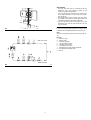
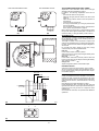
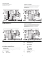
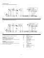
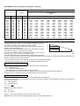
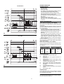
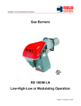
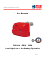
Installation, use and maintenance instructions
Gas Burners
RS 28/M - 38/M - 50/M
Low-High-Low or Modulating Operation
C6505055
CONTENTS
TECHNICAL DATA . . . . . . . . . . . . . . . . . . . . . . . . . . . . . . page
Burner models . . . . . . . . . . . . . . . . . . . . . . . . . . . . . . . . . . . . . . .
Accessories . . . . . . . . . . . . . . . . . . . . . . . . . . . . . . . . . . . . . . . . .
Burner description . . . . . . . . . . . . . . . . . . . . . . . . . . . . . . . . . . . .
Packaging - Weight. . . . . . . . . . . . . . . . . . . . . . . . . . . . . . . . . . . .
Max. dimensions. . . . . . . . . . . . . . . . . . . . . . . . . . . . . . . . . . . . . .
Standard equipment . . . . . . . . . . . . . . . . . . . . . . . . . . . . . . . . . . .
Firing rates . . . . . . . . . . . . . . . . . . . . . . . . . . . . . . . . . . . . . . . . . .
Minimum furnace dimensions. . . . . . . . . . . . . . . . . . . . . . . . . . . .
Gas pressure . . . . . . . . . . . . . . . . . . . . . . . . . . . . . . . . . . . . . . . .
WARNING
If you smell gas:
3
3
3
4
4
4
4
5
5
6
•
•
•
•
Do not touch any electrical items.
Open all windows.
Close all gas supply valves.
Contact your local gas authority immediately.
Do not store flammable or hazardous materials in the vicinity
of fuel burning appliances.
Improper installation, adjustment, alteration, service or maintenance can cause property damage, personal injury or
death. Refer to this manual for instructional or additional information. Consult a certified installer, service representative
or the gas supplier for further assistance.
INSTALLATION . . . . . . . . . . . . . . . . . . . . . . . . . . . . . . . . . . . . . . 7
Boiler plate . . . . . . . . . . . . . . . . . . . . . . . . . . . . . . . . . . . . . . . . . . 7
Blast tube length . . . . . . . . . . . . . . . . . . . . . . . . . . . . . . . . . . . . . 7
Securing the burner to the boiler . . . . . . . . . . . . . . . . . . . . . . . . . 7
Ignition pilot adjustment . . . . . . . . . . . . . . . . . . . . . . . . . . . . . . . . 7
Combustion head adjustment. . . . . . . . . . . . . . . . . . . . . . . . . . . . 8
Gas piping . . . . . . . . . . . . . . . . . . . . . . . . . . . . . . . . . . . . . . . . . . 9
Adjustments before first firing. . . . . . . . . . . . . . . . . . . . . . . . . . . 10
Servomotor. . . . . . . . . . . . . . . . . . . . . . . . . . . . . . . . . . . . . . . . . 10
Burner starting . . . . . . . . . . . . . . . . . . . . . . . . . . . . . . . . . . . . . . 10
Burner firing . . . . . . . . . . . . . . . . . . . . . . . . . . . . . . . . . . . . . . . . 10
Burner calibration: . . . . . . . . . . . . . . . . . . . . . . . . . . . . . . . . . . . 11
1 - Firing output . . . . . . . . . . . . . . . . . . . . . . . . . . . . . . . . . . . . . 11
2 - Maximum output . . . . . . . . . . . . . . . . . . . . . . . . . . . . . . . . . . 11
3 - Minimum output. . . . . . . . . . . . . . . . . . . . . . . . . . . . . . . . . . . 12
4 - Intermediates outputs . . . . . . . . . . . . . . . . . . . . . . . . . . . . . . 12
5 - Air pressure switch . . . . . . . . . . . . . . . . . . . . . . . . . . . . . . . . 13
6 - Low gas pressure switch . . . . . . . . . . . . . . . . . . . . . . . . . . . . 13
Flame present check . . . . . . . . . . . . . . . . . . . . . . . . . . . . . . . . . 13
Maintenance. . . . . . . . . . . . . . . . . . . . . . . . . . . . . . . . . . . . . . . . 14
Factory wiring diagram - burner mounted LFL . . . . . . . . . . . . . . 15
Field wiring diagram - burner mounted LFL . . . . . . . . . . . . . . . . 16
Factory wiring - remote panel. . . . . . . . . . . . . . . . . . . . . . . . . . . 17
Appendix - Burner firing rates according to air density. . . . . . . . 18
Siemens LFL control sequence of operations . . . . . . . . . . . . . . 19
Siemens LFL control troubleshooting guide . . . . . . . . . . . . . . . . 20
Start up report . . . . . . . . . . . . . . . . . . . . . . . . . . . . . . . . . . . . . . 21
Burner shall be installed in accordance with manufacturers
requirements as outlined in this manual, local codes and authorities having juristiction.
N.B.
Figures mentioned in the text are identified as follows:
1)(A)
= part 1 of figure A, same page as text;
1)(A)p.4 = part 1 of figure A, page number 4.
2
TECHNICAL DATA
Model
Output (1)
MAX.
MIN.
Fuel
- Max delivery
- Pressure at maximum delivery (2) natural gas
Operation
Standard application
Ambient temperature
Combustion air temperature
Main power supply (+/-10%)
Fan motor
MBtu/hr
kW
MBtu/hr
kW
RS 28/M
617 - 1232
181 - 361
198
58
SCFH
“ WC
1232
2.95
°F
°F max
V/Ph/Hz
rpm
W - HP
V
A
µV
V1 - V2
I1 - I2
W max
Motor capacitor
Ignition transformer
Electrical power consumption
Electrical protection
Noise levels (3)
dBA
68
RS 38/M
RS 38/M
RS 50/M
880 - 1665
880 - 1665
1099 - 2201
258 - 488
258 - 488
322 - 645
266
266
321
78
78
94
Natural or propane gas
1665
1665
2201
2.6
2.6
2.83
Low - high-low or modulating
Boilers: water, steam, thermal oil
32 - 104 (0 - 40 °C)
140 (60 °C)
120/1/60
208-230/460/575/3/60
3400
3400
370 - 0.5
550 - 0.75
120
208-230/460/575
5.2
3.2 - 1.6 - 1.3
45
120 V - 1 x 7 kV
1.6 A - 23 mA
600
750
NEMA 1
70
70
72
(1) Reference conditions: Ambient temperature 68 °F (20 °C) - Barometric pressure 394” WC - Altitude 329 ft.
(2) Pressure at test point 8)(A)p.4, with zero pressure in the combustion chamber, with open gas ring 2)(B)p.8 an maximum burner output
(3) Sound pressure measured in manufacturer’s combustion laboratory, with burner operating on test boiler and at maximum rated output.
Burner models designation:
Code
C9521300 (3781070)
C9621300 (3781072)
C9522300 (3781270)
C9622300 (3781272)
C9522350 (3781470)
C9522351 (3781470)
C9622350 (3781472)
C9622351 (3781472)
C9523300 (3781670)
C9523301 (3781670)
C9623300 (3781672)
C9623301 (3781672)
Model
RS 28/M
RS 38/M
RS 50/M
Voltage
120/1/60
120/1/60
120/1/60
120/1/60
208-230/460/3/60
575/3/60
208-230/460/3/60
575/3/60
208-230/460/3/60
575/3/60
208-230/460/3/60
575/3/60
Flame safeguard
Burner mounted
Remote panel
Burner mounted
Remote panel
Burner mounted
Burner mounted
Remote panel
Remote panel
Burner mounted
Burner mounted
Remote panel
Remote panel
ACCESSORIES (optional):
•
Kit for LPG operation: The kit allows the RS 28-38-50/M burners to operate on LPG.
RS 28/M
RS 38/M
RS 50/M
358 - 1232
437 - 1665
549 - 1986
Burner
Output
MBtu/hr
Blast tube length
inch
81/2“
Code
•
1313/16“
81/2“
3010270
3010271
81/2“
1313/16“
3010272
Modulating control kit: Under modulating operation, the burner automatically adapts to one of an infinite number of firing rates between the low
and high flame output position, thus ensuring stable operating conditions in terms of temperature or pressure. Two components should be ordered: •
Modulating control to install to the burner; • probe to install to the boiler.
Parameter to be checked
Temperature
Pressure
•
1313/16“
Range
- 212...+ 932 °F (- 100...+ 500 °C)
0...36.3 PSI (0...2.5 bar)
0...232 PSI (0...16 bar)
Probe
Type
Code
PT 100
3010110
Output probe
3010213
4...20 mA
3010214
Gas train according to UL Standards: see page 9.
Important:
The installer is responsible for the supply and installation of any required safety device(s) not indicated in this manual.
• Kit for lengthening the combustion head
L
= Standard length
L1 = Length obtainable with the kit
COD. 3010256
L = 81/2”
COD. 3010257
L = 81/2”
COD. 3010258
L = 81/2”
L1 = 1313/16“
L1 = 13 13/16”
L1 = 13 13/16”
• RS 28/M
• RS 38/M
• RS 50/M
3
Modulating control
Type
Code
RWF40
3010212
BURNER DESCRIPTION (A)
1
2
3
4
5
6
7
8
9
10
11
D2256
12
13
14
15
16
17
18
19
20
D2257
21
22
23
24
25
26
D2258
(A)
inch
A
B
C
Two types of burner failure may occur:
• FLAME SAFEGUARD LOCK-OUT:
if the flame relay 22)(A) pushbutton lights up, it indicates that the burner is in lock-out.
To reset, press the pushbutton.
• MOTOR TRIP (RS 38 - 50 three-phase):
release by pressing the pushbutton on thermal overload 20)(A).
lbs
RS 28/M
3931/32“ 2413/16“ 1911/16“
84
RS 38/M
3931/32“ 2413/16“ 1911/16“
88
RS 50/M
3931/32“ 2413/16“ 1911/16“
91
Combustion head
Ignition electrode
Screw for combustion head adjustment
Sleeve
Low air pressure switch
(differential operating type)
Flame sensor probe (flame rod)
Air pressure test point
Gas pressure test point and head fixing screw
Screws securing fan to sleeve
Slide bars for opening the burner and inspecting the
combustion head
Servomotor controlling the gas butterfly valve and air
damper (by means of a variable profile cam mechanism).
When the burner is not operating the air damper is
fully closed in order to reduce heat loss.
Plate with four hole knock-outs for electrical cable
routing
Air inlet to fan
Gas input connection
Gas butterfly valve
Boiler mounting flange
Flame stability disk
Flame inspection window
Ignition pilot
Motor contactor and thermal overload reset button
(RS 38 - 50 three-phase)
Plug-socket on flame rod probe cable
Flame safeguard
Power switch for different operations:
automatic - manual - off
Switch for:
manual modulation of servomotor
Burner terminal strip
Air damper
Bracket for mounting the PID modulating controller
RWF40 (optional)
D88
(B)
PACKAGING - WEIGHT (B) - Approximate measurements
• The burners are shipped in cardboard boxes with the
maximum dimensions shown in Table (B).
• The weight of the burner complete with packaging is
indicated in table (B).
MAX. DIMENSIONS (C)
Approximate measurements
The maximum dimensions of the burners are given in
(C).
Note that if you need to examine the combustion head,
the burner must be pulled backward on the slide bars
and turned upward.
The maximum dimension of the burner, without the
cover, when open is give by measurement H.
D495
RS
A
B
C
D (1)
28 1823/32“ 1821/32“ 2213/16“ 81/2-1313/16“
E
F
G
H
I
L
M
51/2“ 1327/32“ 67/16“ 317/8“ 41/4“ 65/8“ 11/2”
38 1823/32“ 1821/32“ 2213/16“ 81/2“-1313/16“ 51/2“ 1327/32“ 67/16“ 317/8“ 41/4“ 65/8“ 11/2”
50 1823/32“ 1821/32“ 2213/16“ 81/2“-1313/16“ 531/32“ 1327/32“ 67/16“ 317/8“ 41/4“ 65/8“ 11/2”
(1) Blast tube: short - long (with kit)
(C)
4
STANDARD EQUIPMENT
1 - Gas train flange
1 - Flange gasket
4 - Flange fixing screws
1 - Thermal insulation screen
4 - Screws to secure the burner flange to the boiler:
3/ 8 W x 1”
1 - Instruction booklet
1 - Spare parts list
FIRING RATES (A)
Combustion chamber pressure
“WC
During operation, burner output varies between:
• MAXIMUM OUTPUT, selected within area A,
• MINIMUM OUTPUT, which must not be lower than the
minimum limit in the diagram.
RS 28/M
RS 38/M
RS 50/M
= 198 MBtu/hr
= 266 MBtu/hr
= 321 MBtu/hr
58 kW
78 kW
94 kW
Important:
The FIRING RATE value range has been obtained considering an ambient temperature of 68 °F (20 °C), and
an atmospheric pressure of 394” WC and with the combustion head adjusted as shown on page 8.
Note:
The FIRING RATE areas given in figure (A) have been
reduced by 10% with respect to the maximum range that
can be reached.
Combustion chamber pressure
“WC
Consult Appendix on page 18 for operation at different
surrounding temperatures and/or altitudes.
MINIMUM FURNACE DIMENSIONS (B)
The firing rates were set in relation to certified test boilers.
Figure (B) indicates the diameter and length of the test
combustion chamber.
Combustion chamber pressure
“WC
Example:
output 1388 MBtu/hr:
diameter 20 inch - length 4.9 ft.
D2259
Diameter (inches)
Length (feet)
Recommended furnace dimensions
(A)
(B)
D2918
5
GAS PRESSURE
RS 28/M
The adjacent tables are used to calculate manifold pressure taking into account combustion chamber pressure.
∆p (“ WC)
MBtu/hr
kW
Column 1
Pressure loss at combustion head.
Gas pressure measured at test point 1)(B), with:
• Combustion chamber at 0” WC
• Burner operating at maximum output
• A = Gas ring 2)(B)p.8 adjusted as indicated in diagram (C)p. 8.
• B = Gas ring 2)(B) adjusted to zero.
1
2
624
699
795
891
986
1078
1174
1232
183
205
233
261
289
316
344
361
A
B
0.98
1.22
1.57
1.85
2.17
2.48
2.76
2.95
0.98
1.3
1.69
2.05
2.28
2.68
3.07
3.58
0.039
0.039
0.039
0.079
0.079
0.12
0.12
0.12
Column 2
Pressure loss at gas butterfly valve 2)(B) with maximum
opening: 90°.
Calculate the approximate maximum output of the
burner as follows:
- subtract the combustion chamber pressure from the
gas pressure measured at test point 1)(B).
- Find the nearest pressure value to your result in column 1A or B of the table for the burner in question.
- Read off the corresponding output on the left.
RS 38/M
∆p (“ WC)
MBtu/hr
kW
1
2
870
979
1099
1211
1327
1440
1552
1665
255
287
322
355
389
422
455
488
A
B
1.02
1.22
1.46
1.69
1.89
2.13
2.36
2.6
1.02
1.38
1.77
2.28
2.72
3.11
3.54
4.21
0.079
0.079
0.12
0.12
0.16
0.16
0.2
0.23
Example - RS 28/M:
• Maximum output operation
• Natural gas
• Gas ring 2)(B)p.8 adjusted as indicated in diagram
(C)p.8.
• Gas pressure at test point 1)(B)
= 2.36“ WC
• Pressure in combustion chamber = 0.79“ WC
2.36 - 0.79 = 1.57“ WC
A maximum output of 795 MBtu/hr shown in Table RS
28/M corresponds to 1.57” WC pressure, column 1A.
This value serves as a rough guide, the effective delivery must be measured at the gas meter.
2
To calculate the required gas manifold pressure at test
point 1)(B), set the maximim output required from the
burner operation:
- find the nearest output value in the table for the burner
in question.
- Read off the pressure at test point 1)(B) on the right in
column 1A or B.
- Add this value to the estimated pressure in the combustion chamber.
RS 50/M
∆p (“ WC)
MBtu/hr
1099
1249
1402
1552
1706
1856
2006
2197
kW
322
366
411
455
500
544
588
644
1
A
B
0.87
1.14
1.42
1.69
1.97
2.2
2.48
2.83
0.87
1.3
1.61
2.01
2.36
2.76
3.15
3.78
0.12
0.16
0.2
0.23
0.28
0.35
0.39
0.47
Example - RS 28/M:
• Required burner maximum output operation:
795 MBtu/hr
• Natural gas
• Gas ring 2)(B)p.8 adjusted as diagram (C)p.8.
• Gas pressure at burner output of 795 MBtu/hr,
taken from table RS 28, column 1A = 1.57” WC
• Pressure in combustion chamber = 0.79” WC
1.57 + 0.79 = 2.36” WC
pressure required at test point 1)(B).
(A)
(B)
D2786
6
INSTALLATION
inch
A
B
RS 28/M
69/32“
813/16“
3/8
W
RS 38/M
69/32“
813/16“
3/8
W
RS 50/M
69/32“
813/16“
3/8
W
BURNER MOUNTING (A)
Drill the combustion chamber mounting plate as shown
in (A).
The position of the threaded holes can be marked using
the head gasket supplied with the burner.
C
D455
(A)
BLAST TUBE LENGTH (B)
The length of the blast tube must be selected according
to the indications provided by the manufacturer of the
boiler, and it must be greater than the thickness of the
boiler door complete with its insulation. The range of
lengths available, L (inches), is as follows:
Blast tube 10):
• short
• long
RS 28/M
8 1/2”
13 13/16”
RS 38/M
8 1/2”
13 13/16”
RS 50/M
8 1/2”
13 13/16”
For boilers with front flue passes 13) or flame inversion
chambers, protective insulation material 11) must be
inserted between the boiler refractory 12) and the blast
tube 10).
This protective insulation must not compromise the
extraction of the blast tube.
For boilers having a water-cooled front, the insulation
11)-12)(B) is not required unless it is required by the
boiler manufacturer.
D2260
(B)
Ignition pilot
SECURING THE BURNER TO THE BOILER (B)
Before securing the burner to the boiler, check through
the blast tube opening to make sure that the flame sensor probe is correctly set in position, as shown in (C).
Now detach the combustion head from the burner,
fig.(B):
- Remove screw 14) and withdraw the cover 15).
- Disengage the swivel coupling 4) from the graduated
sector 5).
- Remove the screws 2) from the slide bars 3)
- Remove screw 1) and pull the burner back on slide
bars 3) by about 4”.
Disconnect the wires from the probe and the electrode and then pull the burner completely off the slide
bars, after removing the split pin from the slide bar 3).
Probe
Secure the flange 9)(B) to the boiler plate, inserting the
head gasket 6)(B). Use the 4 screws, also supplied with
the unit, after first protecting the thread with an anti-seize
product.
The seal between burner and boiler must be airtight.
Electrode
(C)
D2261
If you noticed any irregularities in the positions of the
probe or ignition electrode during the check mentioned
above, remove screw 1)(D), extract the internal part
2)(D) of the head and set up the two components correctly.
IGNITION PILOT ADJUSTMENT
(D)
Place the pilot and electrode as shown in fig. (C).
The pilot works correctly at pressures ranging from 5 12” WC.
Important
To set the pilot without main burner operation, proceed
as follows:
- Move the jumper from terminals "30-V11" to terminals
"30-VP", as given in fig. (E), this way the main valve is
not energized.
- With the burner in the manual position, hold the air
damper in the minimum position and make the setting.
- When the setting is correct, replace the jumper on “30V11”.
D2292
MB - Burner terminal strip
(E)
D2317
7
COMBUSTION HEAD ADJUSTMENT
Installation operations are now at the stage where the
blast tube and sleeve are secured to the boiler as shown
in fig. (A).
There are two possible cases:
A - The MIN burner output is not in the values of
table (D).
In diagram (C), depending on the MAX output, find the
notch to use for adjusting the air and the gas, and then
proceed as follows:
Air adjustment (A)
Turn screw 4)(A) until the notch identified is aligned with
the front surface 5)(A) of the flange.
Gas adjustment (B)
Loosen screw 1)(B) and turn ring 2) until the notch identified is aligned with index 3).
Tighten the screw 1) fully down.
D2315
(A)
(B)
Notches (Air = Gas)
D2262
Example:
the burner RS 38/M varies its output between: MIN =
378.7 and MAX = 1288 MBtu/hr.
The MIN output of 378.7 MBtu/hr is not found in the values of table (D) and therefore diagram (C) is valid, from
which it results that for a MAX output of 1288 MBtu/hr
the gas and air adjustments are done on notch 3, as in
fig. (A) and (B).
In this case the pressure load loss of the combustion
head is given by column 1A page 6.
Note
Diagram (C) shows the ideal settings for the ring 2)(B). If
the gas supply pressure is too low to reach the max output operation pressure indicated on page 6, and if the
ring 2)(B) is not fully open, it can be opened wider by 1
or 2 notches.
Continuing with the previous example, page 6 indicates
that for burner RS 38/M with output of 1288 MBtu/hr a
pressure of approximately 1.81” WC is necessary at test
point 6)(A). If this pressure cannot be reached, open the
ring 2)(B) to notch 4 or 5.
Make sure that the combustion characteristics are satisfactory and free of pulsations.
Burner max output
(C)
MODULATION MINIMUM OUTPUT: when the MIN output is within the value range given
below, the gas ring 2)(B) is adjusted to zero.
RS 28/M
RS 38/M
RS 50/M
198 - 280 MBtu/hr
266 - 375 MBtu/hr
321 - 488 MBtu/hr
58 - 82 kW
78 - 110 kW
94 - 143 kW
B - The MIN burner output is found in the values of the
table (D).
Air adjustment
The same as the previous case: follow diagramm (C).
Gas adjustment
The gas ring 2)(B) is always adjusted to position 0, irrespective of the MAX burner.
In this case the pressure load loss of the combustion
heads is given by column 1B page 6.
Once you have finished setting up the head, refit the
burner 4)(E) to the slide bars 3) at approximately 4” from
the sleeve 5) - burner positioned as shown in fig.(B)p.7 insert the flame rod cable and the ignition electrode
cable and then slide the burner up to the sleeve so that it
is positioned as shown in fig.(E).
Refit screws 2) on slide bars 3).
Secure the burner to the sleeve by tightening screw 1)
and then refit the split pin into one of two slide bars 3).
Reconnect the swivel connector 8) to the graduated sector 7).
Connect gas train and pilot train as shown in fig. (A)
page 9.
(D)
D2263
(E)
8
Important
When fitting the burner on the two slide bars, it is advisable to gently draw out the high tension cable and flame
detection probe cable until they are slightly stretched.
GAS PIPING
• The main gas train must be connected to the gas
attachment 1)(A), using flange 2), gasket 3) and
screws 4) supplied with the burner.
• The main gas train can enter the burner from the right
or left side, depending on which is the most convenient, see fig.(A).
• Gas safety shut-off valves 5)-6)(B) must be as close
as possible to the burner to ensure gas reaches the
combustion head within the safety time range.
• The pilot gas train must be connected to the gas
attachment 5)(A) and can enter the burner from the
right or left side.
1
3
2
(A)
GAS TRAIN (B)
4
It must be type-approved according to required localstandards and is supplied separately from the burner.
D2293
TYPICAL UL SCHEMATIC GAS PIPING
Note
See the accompanying instructions for the gas train layout.
KEY (B)
1 - Gas input pipe
2 - Manual valve
3 - Pressure regulator
4 - Low gas pressure switch
5 - 1st safety shut off valve
6 - 2nd safety shut off valve
7 - Standard issue burner gasket with flange
8 - Gas adjustment butterfly valve
9 - Burner
GAS PILOT LINE
MAIN GAS LINE
(B)
D2294
9
LOW GAS PRESSURE SWITCH
AIR PRESSURE SWITCH
D2548
D2547
(A)
ADJUSTMENTS BEFORE FIRST FIRING
Adjustment of the combustion head, and air and gas
deliveries has been illustrated on page 8.
In addition, the following adjustments must also be
made:
- open manual valves on the gas train.
- Adjust the low gas pressure switch to the start of the
scale (A).
- Adjust the air pressure switch to the zero position of
the scale (B).
- Purge the air from the gas line.
- Fit a U-type manometer (C) to the gas pressure test
point on the sleeve.
The manometer readings are used to calculate MAX.
burner power using the tables on page 6.
Before starting up the burner it is good practice to adjust
the gas train so that ignition takes place in conditions of
maximum safety, i.e. with gas delivery at the minimum.
(B)
SERVOMOTOR (D)
The servomotor provides simultaneous adjustment of
the air damper, by means of the variable profile cam,
and the gas butterfly valve.
The angle of rotation of the servomotor is equal to the
angle on the graduated sector controlling the gas butterfly valve. The servomotor rotates through 90 degrees in
25 seconds.
Do not alter the factory setting for the cams; simply
check that they are set as indicated below:
D2265
BURNER STARTING
Close the control circuit and set switch 1)(E) to “MAN”.
As soon as the burner starts check the direction of rotation of the fan blade, looking through the flame inspection window 18)(A)p.4.
(C)
SERVOMOTOR
RED CAM
BURNER FIRING
Having completed the checks indicated in the previous
heading, the pilot of the burner should fire. If the motor
starts but the flame does not appear and the flame safeguard goes into lock-out, reset and wait for a new firing
attempt.
Pilot adjustment has been illustrated on page. 7.
Having adjusted the pilot, reconnect the main valve and
ignite the main flame; it might require several attemps to
purge the air from the gas lines or to adjust the valve
with little gas.
Once the burner has fired, now proceed with calibration
operations.
BLUE CAM
ORANGE CAM
RESET
(D)
D2266
1
(E)
Red cam
: 90°
Limits rotation toward maximum position.
When the burner is at max output the gas butterfly valve
must be fully open: 90°.
Blue cam
: 0°
Limits rotation toward the minimum position. When the
burner is shut down the air damper and the gas butterfly
valve must be closed: 0°.
Orange cam
: 15°
Adjusts the ignition position and the MIN output.
2
D791
10
BURNER CALIBRATION
1
The optimum calibration of the burner requires an analysis of the flue gases at the boiler outlet.
2
Adjust successively:
1 - First firing output
2 - Max. burner output
3 - Min. burner output
4 - Intermediate outputs between low and high fire
5 - Air pressure switch
6 - Minimum gas pressure switch
D791
(A)
1 - FIRING OUTPUT
Pilot adjustment has been illustrated on page. 7.
2 - MAXIMUM OUTPUT
Maximum output of the burner must be set within the firing rate range shown on page 5.
In the above instructions we left the burner running in
MIN. output operation. Now press switch 2)(A) “increase
output” and keep it pressed until the servomotor has
opened the air damper and the gas butterfly valve to
90°.
Gas calibration
Measure the gas delivery at the meter.
A guideline indication can be calculated from the tables
on page 6, simply read off the gas pressure on the Utype manometer, see fig.(C) on page 10, and follow the
instructions on page 6.
- If delivery needs to be reduced, reduce outlet gas
pressure and, if it is already very low, slightly close
adjustment valve.
- If delivery needs to be increased, increase outlet gas
pressure.
11
Adjusting air delivery
Progressively adjust the end profile of cam 4)(A) by turning the cam adjustment screws as they appear through
the access opening 6)(A).
- Turn the screws clockwise to increase air delivery.
- Turn the screws counter-clockwise to reduce air delivery.
3 - MINIMUM OUTPUT
Minimum output must be selected within the firing rate
range shown on page 5.
Press switch 2)(A)p.11 “output reduction” until the servomotor has closed the air damper and the gas butterfly
valve to 15° (factory set adjustment).
D2267
Adjusting gas delivery
Measure the delivery of gas from the gas meter.
- If this value is to be reduced, decrease the angle of
orange cam (B) slightly by proceeding a little at a time
until the angle is changed from 15° to 13° or 11°....
- If it has to be increased press the switch “output
increase” 2)(A)p.11 (i.e. open the gas butterfly valve
by 10-15°), increase the orange cam angle (B) with
small successive movements, i.e. take it from angle
15° to 17° - 19°....
Then press the switch “output decrease” until the servomotor is taken to the minimum opening position and
measure the gas delivery.
1 Servomotor
2 Cam 4 engaged
/disengages
3 Adjustable profile cam
4 Cam profile adjustment screws
5 Opening for access to screws 5
6 Index for graduated sector 8
7 Graduated sector for gas butterfly valve
Note
The servomotor follows the adjustment of cam only
when the cam angle is reduced. If it is necessary to
increase the cam angle, first increase the servomotor
angle with the switch “output increase”, then increase
the orange cam angle, and at the end bring the servomotor back to the MIN output position with the switch
”output decrease”.
(A)
Adjustment of air delivery
Progressively adjust the starting profile of cam 4)(A) by
turning the screws working throught the access hole
6)(A).
4 - INTERMEDIATE OUTPUTS
Adjustment of gas delivery
No adjustment of gas delivery is required.
Adjustment of air delivery
With the switch 1)(A) page 11 move in intermediate outputs and set the variable profile cam 4) by turning the
screws 5).
- If the burner operation is low-high it is sufficient to set
only minimum and maximum firing rates
- If the burner operation is modulating, all the points of
modulation should be adjusted.
When the adjustment is complete, release the servomotor and manually check there is no binding of the cam.
12
5 - AIR PRESSURE SWITCH (A) - CO CHECK
Adjust the air pressure switch after having performed all
other burner adjustments with the air pressure switch set
to the start of the scale (A).
With the burner operating at min. output, increase adjustment pressure by slowly turning the relative dial clockwise until the burner locks out.
Then turn the dial anti-clockwise by about 20% of the set
point and repeat burner starting to ensure it is correct.
If the burner locks out again, turn the dial anti-clockwise
a little bit more.
AIR PRESSURE SWITCH
Attention:
As a rule, the air pressure switch must prevent the formation of CO.
To check this, insert a combustion analyser into the
chimney, slowly close the fan suction inlet (for example
with cardboard) and check that the burner locks out,
before the CO in the fumes exceeds 400 ppm.
D2548
The air pressure switch may operate in "differential"
operation in two pipe system. If a negative pressure in
the combustion chamber during pre-purging prevents
the air pressure switch from switching, switching may be
obtained by fitting a second pipe between the air pressure switch and the suction inlet of the fan. In this way
the air pressure switch operates as differential pressure
switch.
(A)
LOW GAS PRESSURE SWITCH
6 - LOW GAS PRESSURE SWITCH (B)
Adjust the low gas pressure switch after having performed all the other burner adjustments with the pressure
switch set at the start of the scale (B).
With the burner operating at MAX output, increase adjustment pressure by slowly turning the relative dial
clockwise until the burner locks out.
Then turn the dial anti-clockwise by 0.8” WC and repeat
burner starting to ensure it is uniform.
If the burner locks out again, turn the dial anti-clockwise
again by 0.4” WC.
D2547
FLAME PRESENT CHECK (C)
The burner is fitted with an ionisation system (flame rod)
which ensures that a flame is present. The minimum
current for operation is 6 µA. (or see appropriate documentation of flame safeguard manufacturer)
The burner provides a much higher current, so that controls are not normally required. However, if it is necessary to measure the ionisation current, disconnect the
plug-socket 21)(A)p.4 on the ionisation probe cable and
insert a direct current microamperometer with a base
scale of 100 µA.
Carefully check polarities!
(B)
D795
(C)
13
MAINTENANCE
FLAME INSPECTION WINDOW
Combustion
The optimum calibration of the burner requires an analysis of the flue gases. Significant differences with respect
to the previous measurements indicate the points where
more care should be exercised during maintenance.
Gas leaks
Make sure that there are no gas leaks on the pipework
between the gas meter and the burner.
Flame inspection window
Clean the flame inspection window (A).
Combustion head
Open the burner and make sure that all components of
the combustion head are in good condition, not
deformed by the high temperatures, free of impurities
from the surroundings and correctly positioned. If in
doubt, disassemble the elbow fitting 7)(B).
D484
(A)
Servomotor
Disengage the cam from servomotor and turn it backward and forward by hand to make sure it is free moving.
Now engage cam again.
OPENING THE BURNER
Burner
Check for excess wear or loose screws in the mechanisms controlling the air damper and the gas butterfly
valve. Also make sure that the screws securing the electrical leads in the burner connections are fully tightened.
Clean the outside of the burner, taking special care with
the linkages joints and cam.
Combustion
Adjust the burner if the combustion values found at the
beginning of the operation do not comply with the regulations in force, or do not correspond to good combustion.
TO OPEN THE BURNER (B):
- Switch off the electrical power.
- Remove screw 1) and withdraw cover 2).
- Disengage the swivel coupling 3) from the graduated
sector 4).
- Remove screw 5), the split pin 9) and pull the burner
back by about 4” on the slide bars 6).
- Disconnect the probe and electrode leads and then
pull the burner fully back.
- Turn the burner as shown in the figure and fit the split
pin 9) into one of the slide bar holes so that the burner
remains in position.
Now extract the gas distributor 7) after having removed
the screw 8) and disconnecting the pilot gas line.
TO CLOSE THE BURNER (B):
- Remove the split pin 9) and push the burner until it is
about 4” from the sleeve.
- Re-connect the leads and slide in the burner until it
comes to a stop.
- Refit screw 5), the split pin 9) and pull the probe and
electrode leads gently out until they are slightly
stretched.
- Re-couple the swivel coupling 3) to the graduated
sector 4).
- Connect the pilot gas line.
D2268
(B)
14
Factory Wiring Diagram
RS 28/M - RS 38/M single-phase
With Siemens LFL control
Continuous fan operation
Change the wire connection from terminal 6 to terminal 1,
move the jumper from terminals 12-13 to terminals 4-12
and remove the wire from terminal 13 of control box
as indicated below.
(A)
D2269
D2876
Factory Wiring Diagram
RS 38/M - RS 50/M three-phase
With Siemens LFL control
Continuous fan operation
Change the wire connection from terminal 6 to terminal 1,
move the jumper from terminals 12-13 to terminals 4-12
and remove the wire from terminal 13 of control box
as indicated below.
(B)
D2270
D2877
ELECTRICAL SYSTEM
ELECTRICAL SYSTEM as set up by the manufacturer
LAYOUT (A)
Burner RS 28/M - RS 38/M (single-phase)
DA
MB
MV
PA
RT
S1
-
S2
-
SM
SO
SP
TA
TB
-
LAYOUT (B)
Burners RS 38/M - RS 50/M (three-phase)
• Models RS 38/M and RS 50/M leave the factory preset for 208230 V power supply.
• If 460 V power supply is used, change the motor connection from
delta to star and change the setting of the thermal cut-out as well.
Key to Layouts (A) - (B)
C
- Capacitor
CMV
- Motor contactor
15
Siemens LFL Control box
Burner terminal strip
Fan motor
Air pressure switch
Thermal overload
Switch for following operations:
MAN = manual
AUT = automatic
OFF
Button for:
- = power reduction
+ = power increase
Servomotor
Ionisation probe (flame rod)
Plug-socket
Ignition transformer
Burner ground
ELECTRICAL CONNECTIONS
Field Wiring Diagram
RS 28/M - RS 38/M Single-phase
with burner mounted Siemens LFL control
Use flexible cables according to local Regulations.
LAYOUT (A) - The RS 28/M - RS 38/M models
electrical connection single-phase power supply
LAYOUT (B) - The RS 38/M - 50/M models
electrical connection three-phase power supply
Fuses layout (A) - (B), see table (C).
Wire size when not indicated: AWG18.
(A)
D2271
Field Wiring Diagram
RS 38/M - RS 50/M Three-phase
With Burner mounted Siemens LFL control
KEY TO LAYOUTS (A) - (B)
IN
- Burner manual stop switch
MB - Burner terminal strip
PG - Min. gas pressure switch
PS
- Remote lock-out reset
H1
- Remote lock-out signal
H2
- Burner on signal
H4
- Power on signal
H5
- Permission ok
OCR - High-low control.
OC - Operating control.
HL
- High limit.
VP
- Pilot valve
VP0 - Pilot valve (safety)
V10 - Safety valve
V11 - Adjustment valve
NOTE
The OCR and OC controls are not required when the
PID control RWF40 is connected, as their function is
performed by the RWF40 itself.
LAYOUT (D)
Connection of RWF40 and related probe to RS 2838-50/M burners (modulating operation)
(B)
D2272
RS 38/M
RS 28/M Singlephase
F
A
120 V
120 V
T10
T10
It can be connected to the terminals:
- T1 -T2, to replace the remote control TL
RS 38/M
Three-phase
RS 50/M
Key to layout (D)
BT - Temperature probe
BP - Pressure probe
MB - Burner terminal strip
a - Red
b - Red
c - White
d - White
208 208 460 V 460 V
460 V 575 V
230 V
230 V
T6
T6
Note
The TR and TL load controls are not required when the
RWF40 is connected, as their function is performed by
the RWF40 itself.
T4
T6
T6
T4
(C)
RWF40
NOTES
• The setting of the thermal overload must be according
to the total burner amperage draw.
• Models RS 38-50/M leave the factory preset for 208 230 V power supply. If 460 V power supply is used,
change the motor connection from delta to star and
change the setting of the thermal cutout as well.
(D)
D2322
16
• Models RS 28-38-50/M have been type- approved for
intermittent operation. This means they should compulsorily be stopped at least once every 24 hours to
enable the control box to perform check its own efficiency at start-up. Burner halts are normally provided
for automatically by the boiler load control system.
If this is not the case, a time switch should be fitted in
series to IN to provide for burner shut-down at least once
every 24 hours.
Factor Wiring Diagram
RS 28/M - RS 38/M single-phase with Remote Panel
D2396
(A)
Factory Wiring Diagram
RS 38/M - RS 50/M three-phase with remote panel
D2403
(B)
Key to Layouts (A) - (B)
C
- Capacitor
CMV
- Motor contactor
DA
- Siemens LFL Control box
MB
- Burner terminal strip
MV
- Fan motor
PA
- Air pressure switch
RT
- Thermal overload
S1
- Switch for following operations:
MAN = manual
AUT = automatic
OFF
S2
- Button for:
- = power reduction
+ = power increase
SM
- Servomotor
SO
- Ionisation probe (flame rod)
SP
- Plug-socket
TA
- Ignition transformer
TB
- Burner ground
ELECTRICAL SYSTEM
ELECTRICAL SYSTEM as set up by the manufacturer
LAYOUT (A)
Burner RS 28/M - RS 38/M (single-phase)
The flame safeguard is in remote panel.
See the internal electrical systems of the remote panel in order to
have the complete wiring diagram.
LAYOUT (B)
Burners RS 38/M - RS 50/M (three-phase)
The flame safeguard is in remote panel.
See the internal electrical systems of the remote panel in order to
have the complete wiring diagram.
17
APPENDIX - Burner firing rates according to air density
CORRECTION FACTOR F
above sea level
average barom.
pressure
Air temperature
°F (°C)
ft
m
“ W.C.
mbar
0 (0°C)
41 (5°C)
50 (10°C)
59 (15°C)
68 (20°C)
77 (25°C)
86 (30°C)
104 (40°F)
0
329
658
987
1316
1645
1974
2303
2632
2961
3290
3947
4605
5263
5921
6579
0
100
200
300
400
500
600
700
800
900
1000
1200
1400
1600
1800
2000
399
394
389
385
380
376
372
367
363
358
354
346
337
329
321
313
1013
1000
989
978
966
955
944
932
921
910
898
878
856
836
815
794
1,087
1,073
1,061
1,050
1,037
1,025
1,013
1,000
0,988
0,977
0,964
0,942
0,919
0,897
0,875
0,852
1,068
1,054
1,042
1,031
1,018
1,007
0,995
0,982
0,971
0,959
0,946
0,925
0,902
0,881
0,859
0,837
1,049
1,035
1,024
1,013
1,000
0,989
0,977
0,965
0,954
0,942
0,930
0,909
0,886
0,866
0,844
0,822
1,031
1,017
1,006
0,995
0,983
0,972
0,960
0,948
0,937
0,926
0,914
0,893
0,871
0,851
0,829
0,808
1,013
1,000
0,989
0,978
0,966
0,955
0,944
0,932
0,921
0,910
0,898
0,878
0,856
0,836
0,815
0,794
0,996
0,983
0,972
0,962
0,950
0,939
0,928
0,916
0,906
0,895
0,883
0,863
0,842
0,822
0,801
0,781
0,980
0,967
0,956
0,946
0,934
0,923
0,913
0,901
0,891
0,880
0,868
0,849
0,828
0,808
0,788
0,768
0,948
0,936
0,926
0,916
0,904
0,894
0,884
0,872
0,862
0,852
0,841
0,822
0,801
0,783
0,763
0,743
(A)
The FIRING RATE area values have been obtained considering a surround- “ W.C.
ing temperature of 68°F (20°C), and an atmospheric pressure of 398” W.C.
and with the combustion head adjusted as shown on page 8.
H2
The burner may be required to operate with combustion air at a higher temH3
H1
A
perature and/or at higher altitudes.
Heating of air and increase in altitude produce the same effect: the expansion of the air volume, i.e. the reduction of air density.
D2617
Qe
MBTU/h
The burner fan's delivery remains substantially the same, but the oxygen
(B)
content per cubic meter and the fan's head are reduced.
It is therefore important to know if the maximum output required of the burner
at a given combustion chamber pressure remains within the burner's firing rate range even at different temperature and altitude conditions. Proceed as follows to check the above:
1 -Find the correction factor F in the Table (A) for the plant's air temperature and altitude.
2 -Divide the burner's delivery Q by F in order to obtain the equivalent delivery Qe:
Qe = Q : F (MBtu/hr)
3 -In the firing rate range of the burner, Fig. (B), indicate the work point defined by:
Qe = equivalent delivery
H1 = combustion chamber pressure
The resulting point A must remain within the firing rate range.
4 -Plot a vertical line from Point A as shown in Figure (B) and find the maximum pressure H2 of the firing rate.
5 -Multiply H2 by F to obtain the maximum reduced pressure H3 of the firing rate.
H3 = H 2 x F
(“ W.C.)
If H3 is greater than H1, as shown in Fig. (B), the burner delivers the output required.
If H3 is lower than H1, the burner's delivery must be reduced. A reduction in delivery is accompanied by a reduction of the pressure in
the combustion chamber:
Qr = reduced delivery
H1r = reduced pressure
H1r = H1 x
( QrQ )
2
Example, a 5% delivery reduction:
Qr = Q x 0.95
H1r = H1 x (0.95)2
Steps 2 - 5 must now be repeated using the new Qr and H1r values.
Important: the combustion head must be adjusted in respect to the equivalent delivery Qe.
18
BURNER OPERATION
Full Modulation
BURNER STARTING
• Operating closes.
Fan motor starts.
• Servomotor starts:
90° rotation to right, until contact is made on red cam.
The air damper is positioned to MAX. output.
• Pre-purge stage with air delivery at MAX. output.
• After pre-purge stage, servomotor rotates to left up to
the angle set on blu cam for MIN. output.
• The air damper and the gas butterfly are positioned to
MIN. output.
• Ignition electrode strikes a spark.
• Pilot valve opens. The pilot flame is ignited.
• After about 12 s the main flame ignites and starting
cycle ends.
(A)
D2273
Low - High
STEADY STATE OPERATION
Burner without modulating control RWF40
At the end of the starting cycle, the servomotor control
then passes to the load control for boiler pressure or
temperature.
(The flame safeguard continues, however, to check that
the flame is present and that the air pressure switch is in
the correct position.)
• If the temperature or pressure is low, the burner progressively increases its output to the MAX. value.
• If the temperature or pressure is high, the burner progressively decreases its output to the MIN. value.
And so on.
• The burner locks out when demand for heat is less
than the heat supplied by the burner at min. output.
Load control opens. The servomotor returns to the 0°
angle limited by contact with orange cam. The air
damper closes completely to reduce thermal dispersion to a minimum.
Every time output is changed, the servomotor automatically modifies gas delivery (gas butterfly valve) and air
delivery (fan damper).
Burner with modulating control RWF40
See the handbook enclosed with the modulating control.
Switching times are given in seconds, in the burner startup sequence.
LFL 1.335 Series 01
t1
30
t2
2
t3
4
t4
20
t5
optional
(B)
D2274
t6
t7
t8
t9
optional
12
4
16
Legend for the times
t1
Pre-purge time with air damper open
t2
Safety time
t3
Pre-ignition time, short (ignition transformer on
terminal 16)
t4
Interval between start of t2 and release of valve
at terminal 19
t5
Interval between end of t4 and release of load
controller or valve at terminal 20
t5
Running time of air damper into OPEN position
t6
Running time of air damper into low-flame position (MIN)
t7
Permissible after-burn time
t8
Interval until OPEN command for the air damper
is given
t9
Running time of pilot
FIRING FAILURE
If the burner does not fire, it locks out within 2.5 seconds
from opening the pilot valve and then within 5 seconds
from opening the main valves.
BURNER FLAME GOES OUT DURING OPERATION
If the flame should accidentally go out during operation,
the burner will lock out within 1s.
19
BURNER FAULTS
Control program under fault
conditions and lock-out
indication
In case of any disturbance, the sequence mechanism stops and with it the lock-out indicator. The symbol
above the reading mark of the indicator gives the type of disturbance:
No start, e.g. because one contact is not closed. Lock-out during or after control program sequence
due to extraneous light (e.g. non-extinguished flames, leaking fuel valves, defects in the flame
supervision circuit, etc.)
Interruption of startup sequence, because the OPEN signal has not been delivered to terminal 8
by limit switch “a”. Terminals 6, 7 and 14 remain under voltage until the fault has been corrected!
P
Lockout, because there is no air pressure indication at the beginning of air pressure control.
Every air pressure failure after this moment in time leads to lock-out, too!
Lock-out due to a fault in the flame supervision circuit.
Interruption of startup sequence, because the position signal for the low-flame position has not
been delivered to terminal 8 by auxiliary switch “m”. Terminals 6, 7 and 14 remain under voltage until
the fault has been corrected!
1
Lock-out, because no flame signal is present after completion of the (1st) safety time.
2
Lock-out, because no flame signal has been received on completion of the 2nd safety time (flame
signal of the main flame with interrupted pilot burners).
Lock-out, because the flame signal has been lost during burner operation.
If lock-out occurs at any other moment in time between the start and the pre-ignition wich is not marked by a
symbol, this is usually caused by a premature, i.e. faulty flame signal, e.g. caused by a self-igniting UV tube.
20
BURNER START UP REPORT
Model number:
Serial number:
Project name:
Start-up date:
Installing contractor:
Phone number:
GAS OPERATION
Gas Supply Pressure:
CO2: Low Fire
High Fire
Main Power Supply:
O2: Low Fire
High Fire
Control Power Supply:
CO: Low Fire
High Fire
Burner Firing Rate:
NOX: Low Fire
High Fire
Manifold Pressure:
Net Stack Temp - Low Fire:
High Fire:
Pilot Flame Signal:
Comb. Efficiency - Low Fire:
High Fire:
Low Fire Flame Signal:
Overfire Draft:
High Fire Flame Signal:
OIL OPERATION
Oil supply pressure:
CO2: Low Fire
High Fire
Oil suction pressure:
O2: Low Fire
High Fire
Control Power Supply:
CO: Low Fire
High Fire
Burner Firing Rate:
NOX: Low Fire
High Fire
Low Fire Flame Signal:
Net Stack Temp - Low Fire:
High Fire:
High Fire Flame Signal:
Comb. Efficiency - Low Fire:
High Fire:
Low Fire Nozzle Size:
Overfire Draft:
High Fire Nozzle Size:
Smoke number:
CONTROL SETTINGS
Operating Setpoint:
Low Oil Pressure:
High Limit Setpoint:
High Oil Pressure:
Low Gas Pressure:
Flame Safeguard Model Number:
High Gas Pressure:
Modulating Signal Type:
NOTES
21
Reliable Combustion Solutions
35 Pond Park Road
Hingham, Massachusetts,
U.S.A. 02043
1-800-4-RIELLO
1-800-474-3556
www.riello-burners.com
2165 Meadowpine Blvd.
Mississauga, Ontario,
Canada L5N 6H6