1
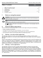
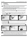
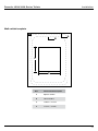
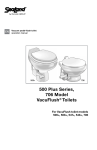
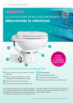
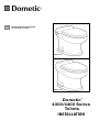
EN
Gravity-discharge Toilet
Installation manual
DE
Mazerier-WC
Bedienungsanleitung . . . . . . . . . . . . . 13
FR
WC dilacérateur
Mode d’emploi . . . . . . . . . . . . . . . . . 22
ES
Inodoro triturador
Manual de instrucciones . . . . . . . . . . 32
NL
Toilet met versnijdingspomp
Instructihandleiding . . . . . . . . . . . . . . 42
IT
WC di macerazione
Manuale di istruzioni . . . . . . . . . . . . . 51
FI
Silppuripumppu-wc
Ohjekirja . . . . . . . . . . . . . . . . . . . . . . 60
SV
Macerator-toalett
Bruksanvisning . . . . . . . . . . . . . . . . . 69
DA
Findelingstoilet
Instruktionsvejledning . . . . . . . . . . . . 78
NO
Macerator-toalett
Brukerhåndbok . . . . . . . . . . . . . . . . . 87
4300 series
4400 series
Dometic®
4300/4400 Series
Toilets
INSTALLATION
1
Notes on using the manual
1
Dometic 4300/4400 Series Toilets
2
9
1
10
11
2
B
8
C
12
G
3
7
A
D
4
5
F
6
2
E
Dometic 4300/4400 Series Toilets
General safety instructions
Table of contents
1
2
3
4
5
6
1
EN
Notes on using the manual . . . . . . . . . . . . . . . . . . . . . . . . . . . . . . . . . . . . . . . . . . . . . . . . . 3
General safety instructions . . . . . . . . . . . . . . . . . . . . . . . . . . . . . . . . . . . . . . . . . . . . . . . 3 - 4
Components . . . . . . . . . . . . . . . . . . . . . . . . . . . . . . . . . . . . . . . . . . . . . . . . . . . . . . . . . . . . 4
Specifications . . . . . . . . . . . . . . . . . . . . . . . . . . . . . . . . . . . . . . . . . . . . . . . . . . . . . . . . . . . 5
Installation . . . . . . . . . . . . . . . . . . . . . . . . . . . . . . . . . . . . . . . . . . . . . . . . . . . . . . . . . . 6 - 11
Customer service . . . . . . . . . . . . . . . . . . . . . . . . . . . . . . . . . . . . . . . . . . . . . . . . . . . . . . . 12
Notes on using the manual
Caution!
Safety Instruction: Failure to observe this instruction can cause material damage and
impair the function of the device.
Note
Supplementary information for operating the device.
fig. 1 A, page 2 : This refers to an element in an illustration. In this example, item A in
figure 1 on page 2.
2
General safety instructions
The manufacturer will not be held liable for claims for damage resulting from the following:
• Faulty assembly or connection
• Damage to the unit from mechanical influences, misuse or abuse
• Alterations to the unit without express written permission from the manufacturer
• Use for purposes other than those described in the operating manual
2.1
Warning – recreation vehicle applications
The following statement must be read and understood before installing, servicing and/or
operating this product on a recreation vehicle. Modification of this product may result in property
damage.
Dometic recommends that a qualified RV technician or electrician install or service this product with
regard to all applicable codes and regulations. Equipment damage, personal injury or death could
result from improper installation. DOMETIC ACCEPTS NO RESPONSIBILITY OR LIABILITY FOR
DAMAGE TO EQUIPMENT, OR PERSONAL INJURY OR DEATH THAT MAY RESULT FROM IMPROPER
INSTALLATION, SERVICE OR OPERATION OF THIS PRODUCT.
2.2
Warnings – marine applications
The following statements must be read and understood before installing, servicing and/or
operating this product on a boat. Modification of this product may result in property damage.
Dometic recommends that a qualified marine technician or electrician install or service this product.
Equipment damage, injury to personnel or death could result from improper installation. DOMETIC
ACCEPTS NO RESPONSIBILITY OR LIABILITY FOR DAMAGE TO EQUIPMENT, OR PERSONAL
INJURY OR DEATH THAT MAY RESULT FROM IMPROPER INSTALLATION, SERVICE OR OPERATION
OF THIS PRODUCT.
3
General safety instructions
Dometic 4300/4400 Series Toilets
Caution! Hazard of Flooding
If toilet rim is below the waterline at ANY time (during any conditions of heel, load or trim)
and is connected to ANY through-the-hull fittings, properly positioned ventilated (vented)
loops MUST be installed in intake* or discharge piping to prevent potential back siphonage
of seawater into the boat. Failure to do so can result in flooding which can cause loss of
property and life.
* if connected to raw water
Caution! Hazard of Flooding
If toilet uses raw water for flushing at ANY time, a raw water pump controlled by an automatically operating demand switch MUST NOT be installed. If the onboard water valve or
any plumbing connections were to leak, the automatically operated pump would start and
could flood the boat. Failure to comply can cause loss of property and life.
2.3
Warnings – all applications
Caution! Hazard of Flooding
If the toilet uses fresh water for flushing and is connected directly or indirectly to a
municipal water system at ANY time, water connections MUST be disconnected if the
vehicle is unattended (even if vehicle is unattended for a brief period). Failure to do so can
result in flooding which can cause loss of property and life.
Caution!
Overfilling the holding tank can create serious damage to the sanitation system, such as
rupturing the holding tank and releasing tank contents. To prevent this possibility, Dometic
recommends using the “full” tank shut-down relay in the toilet’s electronic control module.
The “full” signal from the holding tank can be generated by an optional Dometic DTM01C
tank monitor or DTM04 four-level tank monitor system.
Caution! Hazard of Shock or Fire
Always use recommended fuse, circuit breaker and wire size. Failure to do so can result in
fire that can cause the loss of property and life.
3
Components
(fig. 1 , page 2)
Ref.
4
Description
Ref.
Description
1
Vacuum breaker
8
Manual flush lever
2
Bowl water supply hose
9
Manual flush lever access cover
3
Water valve
10
Flush handle (4400 series)
4
Plug-in discharge fitting
11
Flush handle cable connector
(4400 series)
5
O-ring
12
Flush switch (4300 series)
6
Water line/connector
7
Flush ball motor/drive linkage
Refer to complete parts list (packed separately)
for additional information.
Dometic 4300/4400 Series Toilets
4
Specifications
4.1
Materials
Specifications
Toilet: vitreous ceramic
Dometic switch panel (4300 series): polycarbonate resin
Flush handle (4400 series): plated brass
4.2
Minimum System Requirements
Electrical
Water
Supply
Discharge
Circuit breaker
2 amps/12 V DC
Wiring
14 gauge stranded copper
Fitting
0.5 in. NPT
Flow rate
4 gpm/15 lpm minimum at toilet
Maximum flow pressure
40 PSI / 276 kPa
Fitting
4-bolt floor (closet) flange. 3-in. (76 mm) ID
ABS or PVC connection to holding tank
Specifications are subject to change without notice.
4.3
Dimensions (fig. 2 , p. 2)
Models with wall-mounted flush
switch
Ref.
Dimension
All dimensions may vary ±3/8 inch (10 mm)
Models with flush handle
Ref.
Dimension
A
19 in. / 483 mm
A
19 in. / 483 mm
B
14.75 in. / 375 mm
B
15.875 in. / 403 mm
C
21.5 in. / 546 mm *
C
21.5 in. / 546 mm *
D
17.75 in. / 451 mm - seat height
D
17.75 in. / 451 mm - seat height
E
17.125 in. / 435 mm *
E
17.125 in. / 435 mm *
F
10 in. / 254 mm - centerline
rough-in *
F
10 in. / 254 mm - centerline
rough-in *
G
33.75 in. / 857 mm - seat lid up
G
33.75 in. / 857 mm - seat lid up
* For toilet models with hand sprayer, add 0.25 in. / 6.3 mm to dimensions C, E, F to allow small space
between toilet and wall.
5
Installation
5
Installation
5.1
Toilet installation
Dometic 4300/4400 Series Toilets
Note
If replacing an existing gravity-discharge toilet, make sure the center of the existing
discharge flange is at least 10 inches (254 mm) from the back wall, then proceed to
Step 5 for proper positioning of water line and electrical wiring.
1. Carefully unpack the toilet bowl and floor flange adapter.
2. Position the ceramic bowl in the space intended. Confirm that adequate clearance is available
for using the flush handle and opening the seat and lid.
3. Mark the floor at the rear corners of the toilet bowl (fig. 3 ). Measure the distance between
the two marks and divide by 2 to find the toilet centerline. Mark the floor at the rear wall for the
centerline.
4. Place a carpenter’s square against the back wall, and draw a center line on the floor at least
14 inches (356 mm) long (fig. 4 ). Mark the centerline for the floor flange at 10 inches (254 mm)
from the wall (fig. 5 ). Add 0.25 in. (6 mm) to distance from wall if installing model with
hand sprayer attached to toilet.
3
4
5
5a.For through-the-floor water line and electrical wires, mark another centerline 6 inches (152 mm)
from the back wall (fig. 6 ).
5b.For through-the-wall water line and electrical wires, mark a centerline 8 inches (203 mm) up from
the floor centerline (fig. 7 ).
6. Make a 4-3/4 inch (121 mm) diameter hole (for most floor flanges) or a 5-1/8 inch (130 mm)
diameter hole (for swivel joint floor flange) at the centerline mark furthest from the wall. Make a
1 inch (25 mm) hole at the mark closer to the wall for the water line and electrical wires (fig. 8 ).
6
7
8
Caution
The preferred floor flange installation method is to mount the floor flange directly on the
finished floor. However, if the bottom of floor flange and bottom of ceramic toilet must be
mounted at different heights, the floor flange must be mounted within 3/8 inch (10 mm) of
the bottom of the toilet (see illustrations on next page) or leakage may result.
6
Dometic 4300/4400 Series Toilets
Installation
Above-Floor Installation
Below-Floor Installation
7. Insert floor flange into larger hole and secure to the floor with #12x3/4-inch long flat head wood
or sheet metal screws (fig. 9 ).
8. Route 1/2-inch (13 mm) PEX tubing through the smaller hole and install a PEX 1/2-inch NPT
fitting (fig. 10 ).
Note
A water shut-off valve should be installed in the water line to the toilet for maintenance
requirements.
9. WITH THE ELECTRICAL POWER OFF, route #14 gauge stranded copper wire from 12 VDC
ground and positive 12 VDC from the fuse panel through a 2-amp fuse or circuit breaker. Leave
at least 12 inches (305 mm) of wire for connecting to toilet (fig. 11 ).
9
11
10
10.Connect the holding tank to the bottom of the discharge flange.
11.Slide four T-bolts into the slots of floor flange. Install the flange gasket over the T-bolts (fig. 12 ).
12.Install floor flange adapter with words “THIS SIDE UP” facing up. Tighten adapter to floor flange
using four flat washers and hex nuts. Tighten in criss-cross pattern (fig. 13 ).
12
13
7
Installation
Dometic 4300/4400 Series Toilets
Caution
If replacing an existing toilet that uses a 2-bolt floor flange, drill two 5/16-inch dia. holes in
old floor flange that align with two additional holes in floor flange adapter. Use two #10 or
12 x 1-1/2-inch wood screws and washers for these drilled holes, and two T-bolts with flat
washers and nuts to fasten flange gasket and floor flange adapter to old floor flange.
Do not use old hardware or seal.
13.Remove red cap from flange adapter, lubricate O-ring with silicone grease, and
temporarily set the toilet in place on the floor flange (fig. 14 ).
14.Mark the holes for the two toilet mounting bolts (fig. 15 ).
15.Pick up toilet and set aside. Drill 3/16-inch pilot holes in the floor (fig. 16 ).
14
15
16
16.With toilet close to floor flange, connect flexible water supply hose to water line fitting (fig. 17 ).
17.Connect the positive (+) 12 VDC wire to the red power wire that’s connected to the toilet base.
Connect the negative (-) 12 VDC wire to the black wire (fig. 18 ).
17
18
Note: If installing model 4410 toilet with remote switch
Install wall switch according to instructions on page 10. Route wall switch wires up through
water line hole.
Caution
DO NOT ATTEMPT TO SLIDE THE TOILET OVER THE FLANGE ADAPTER. THE TOILET
MUST BE SET DOWN OVER THE ADAPTER TO PREVENT POSSIBLE DAMAGE.
8
Dometic 4300/4400 Series Toilets
Installation
18.Set the toilet in place on the floor flange (fig. 19 ) and secure to floor with #14x2-1/2 inch long
lag bolts (fig. 20 ). Install decorative bolt caps by pushing them onto bolt heads (fig. 21 ).
19.Turn on electrical power and water to toilet. Lift flush handle and fill toilet bowl with water. Wait
one hour, then inspect the floor around and under the rear of the toilet for leaks or dampness.
If no leaks are present, toilet is ready for operation.
19
20
21
Wiring diagram
22
9
Installation
5.2
Dometic 4300/4400 Series Toilets
Wall switch installation – 4400 series toilet
1. Select a location for the switch. 8 feet of cable (2.4 m) is
provided. More wire may be required, depending on how far the 23
switch is located from the toilet.
2. Cut an opening 1-1/4 in. wide x 1-5/8 in. high (fig. 25 ,
page 11).
3. If installing the switch in a shallow wall, you may need to use
the spacer between the wall and the switch assembly cover
to allow space for the wire connectors. If so, route the cable
through the spacer before proceeding to the next step.
4. Route the 3-conductor cable through wall cut-out and on to toilet. Cable can be routed through
hole with water supply line and power wires (fig. 23 ). Leave a minimum of 12 inches (305 mm)
of cable to allow easy wiring at toilet.
5. Fasten the switch assembly to the wall with the #6x1 in. screws (included), making sure to install
with the label “THIS SIDE UP” on top (fig. 24 ). Otherwise, the “Flush” and “Add Water” functions will be reversed.
6. Snap cover onto switch assembly to complete switch installation on wall.
7. WITH THE ELECTRICAL POWER OFF, connect the red, black and white wires from the switch
to the red, black and white wires of the Remote Flush Cable from the toilet (fig. 23 ).
24
10
Dometic 4300/4400 Series Toilets
Installation
Wall switch template
25
A
B
C
D
Ref.
Dimension/Description
A
Spacer outline
B
Cover outline
C
1.625 in. / 41 mm
D
1.25 in. / 32 mm
11
Customer service
6
Dometic 4300/4400 Series Toilets
Customer service
There is a strong, worldwide network to assist
in servicing and maintaining your sanitation
system. For the Authorized Service Center near
you, please call from 8:00 a.m. to 5:00 p.m. (ET)
Monday through Friday.
You may also contact or have your local
dealer contact the Parts Distributor nearest
you for quick response to your replacement
parts needs. They carry a complete inventory
for the Dometic product line.
Telephone:
1 800-321-9886 330-496-3211 U.S.A. and Canada
International
Fax:
330-496-3097 330-496-3220 U.S.A. and Canada
International
Web site:
http://www.Dometic.com
Dometic Group is a customer-driven, world-leading provider of leisure
products for the RV, automotive, truck and marine markets. We supply
the industry and aftermarket with a complete range of air conditioners,
refrigerators, awnings, cookers, sanitation systems, lighting, mobile
power equipment, comfort and safety solutions, windows, doors and
other equipment that make life more comfortable away from home.
Dometic Group supplies a wide range of workshop equipment for
service and maintenance of built-in air conditioners. Dometic Group
also provides specially designed refrigerators for hotel rooms, offices,
wine storage and transport and storage of medical products.
Our products are sold in almost 100 countries and are produced mainly
in wholly-owned production facilities around the world.
® Registered; ™ Trademark of Dometic Corporation
© Dometic Corporation
600346540
04/10
12
DOMETIC CORPORATION
13128 SR 226 | PO BOX 38
BIG PRAIRIE, OHIO 44611 USA
www.dometic.com