1
P73043/F1U127uKIT univ/man.qxd
4/28/00
1:58 PM
Page 1
Bitronics DualBus Switch Kit
User Manual
Kit du commutateur Bitronics DualBus
Guide de l’utilisateur
Bitronics DualBus Switch Set
Benutzerhandbuch
En
Fr
De
Bitronics DualBus Switch Kit
Handleiding
Bitronics DualBus Switch Kit
Manuale dell’Utente
Ne
It
P73043
F1U127-KIT
P73043/F1U127uKIT univ/man.qxd
4/28/00
1:58 PM
Page 2
P73043/F1U127uKIT univ/man.qxd
4/28/00
1:58 PM
Page 3
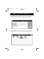
Table of Contents
English . . . . . . . . . . . . . . . . . . . . . . . . . . . . . . . . . . . . . . . . . 1
En
Fr
Français (Europe) . . . . . . . . . . . . . . . . . . . . . . . . . . . . . . . . 37
Deutsche . . . . . . . . . . . . . . . . . . . . . . . . . . . . . . . . . . . . . . . 75
De
Nederlands . . . . . . . . . . . . . . . . . . . . . . . . . . . . . . . . . . . . 113
Ne
Italiano . . . . . . . . . . . . . . . . . . . . . . . . . . . . . . . . . . . . . . . 149
It
P73043/F1U127uKIT univ/man.qxd
4/28/00
1:58 PM
Page 4
P73043/F1U127uKIT univ/man.qxd
4/28/00
1:58 PM
Page 1
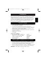
Introduction
En
Thank you for purchasing the Belkin Components Bitronics DualBus Switch
Kit! Now, you and your colleagues can share and select between two
different parallel devices from your desktop. And, if you are using
Windows® 95, 98 or NT®, you will be able to take advantage of Bitronics
Software, which allows you to print automatically even if you have more
than one printer!
Features
•
Allows two computers to access any two parallel devices simultaneously
and independently
•
Virtual Port printer driver software allows fully automatic printer selection
through Windows® 95/98 and NT®
•
File-transfer feature between two PCs compatible with Windows® Direct
Cable Connection, LapLink® and DOS Interlink™
•
Includes two 6 ft. (1.8m) IEEE 1284-compliant cables to connect the computers
•
Includes power adapter
•
Adjustable timeout
Package Contents:
Bitronics DualBus Switch, 2-2
F1U127
Power Adapter, 9VDC, 600mA
F1D065-PWR-IT
2 x IEEE 1284-compliant cables
F2A047-06
User manual
P73043-EU
Registration card
P72009
Other Parts Needed (if necessary)
•
IEEE 1284 printer cable, Belkin Part# F2A046-XX. You will need this
cable to connect a printer to the autoswitch. Your current printer cables
may work, but IEEE-compliant cables are recommended.
•
IEEE 1284 device cable, Belkin Part# F2A047-XX. You will need this
cable to connect a computer to the autoswitch.
NOTE: "XX" is the length in feet.
1
P73043/F1U127uKIT univ/man.qxd
4/28/00
1:58 PM
Page 2
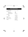
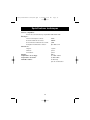
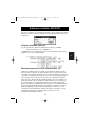
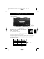
Technical Specifications
Compatible Standards:
IEEE 1284-1994 Parallel Port Communication Standard
Electrical:
Input Voltage
Max Input Current
Max Power Consumption
Max Heat Dissipation
9VDC
600mA
5.4W
0.31 BTU/min
Dimensions:
Width:
Height:
Depth:
Weight:
Storage Temperature:
7.0” (17.8cm)
3.75” (9.5cm)
1.25” (3.2cm)
7.1 oz. (202 g)
-10ºC to 50ºC
(14ºF to 122ºF)
0ºC to 40ºC
(32ºF to 104ºF)
0 to 95%
Non-condensing
Operating Temperature:
Humidity:
2
P73043/F1U127uKIT univ/man.qxd
4/28/00
1:58 PM
Page 3
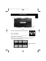
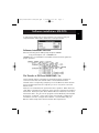
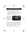
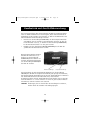
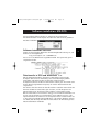
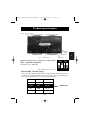
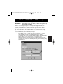
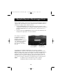
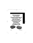
Product Detail
En
Device activity LEDs
Connector to Device B
Connector to Device A
DC power jack
(side)
Connector to PC1
Connector to PC2
PC activity LEDs
DIP switch settings (located underneath switch):
SW1:
Computer button
Printer button
ON
DIP
Reset Switch
To reset, OFF→ON→OFF
ON is UP. SW4 is not used.
1
2
3 4
SW2 and SW3: TimeOut Setting
TimeOut is the amount of time the switch remains locked on a PC port after
data transfer. Use a longer TimeOut when connecting to scanners, mass
storage devices and for large print jobs.
SW2
SW3
TimeOut
ON
ON
5 seconds
ON
OFF
10 seconds
OFF
ON
20 seconds
OFF
OFF
40 seconds
3
Recommended
P73043/F1U127uKIT univ/man.qxd
4/28/00
1:58 PM
Page 4
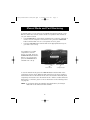
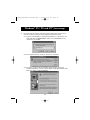
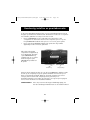
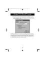
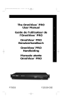
Manual Mode and Port Monitoring
In manual mode, you can select a port manually through the buttons on the
Bitronics switch. You can also use this mode in conjunction with software to
see your switch in action!
•
Press COMPUTER to select which computer port you wish to configure or
monitor. For the computer connected to Port 1, press the COMPUTER
button until the LED on Port 1 is lit up either in red or green.
•
Press the PRINTER button until the LED of the appropriate device port
you wish to use is lit up.
For example, if you want
computer 2 to use the
device on port B, press the
COMPUTER button until the
LED on "2" is lit up. Then,
press the PRINTER button
until LED "B" is lit up.
Printer button
Computer button
To use File Transfer mode, press the PRINTER button until the LED on the
computer port turns green. When the LED turns green, the port is ready for
file transfer mode. For file transfer mode to be successful for both PCs, both
computer ports must be set to file transfer mode – which is evident when the
LEDs next to 1 and 2 are green. For more information on File Transfer, please
see page 25.
NOTE: If you change the ports manually using the buttons, the changes
made will not be reflected in the software.
4
P73043/F1U127uKIT univ/man.qxd
4/28/00
1:58 PM
Page 5
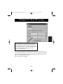
Choose your operating system
En
Windows 3.x . . . . . . . . . . . . . . . . . . . . . . . . . . . . . . . . . . . . . . . . . Page 6
®
MS-DOS . . . . . . . . . . . . . . . . . . . . . . . . . . . . . . . . . . . . . . . . . . . . . Page 7
Windows® 95/98 and NT® . . . . . . . . . . . . . . . . . . . . . . . . . . . . . . . . . Page 8
NOTE: When installing software on any operating system, the
software must be installed on all the computers connected to the
Bitronics switch so that each machine can control the
switch properly.
5
P73043/F1U127uKIT univ/man.qxd
4/28/00
1:58 PM
Page 6
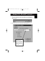
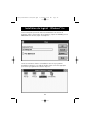
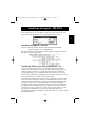
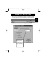
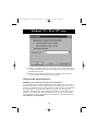
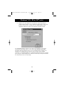
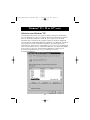
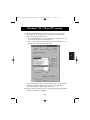
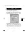
Software installation: Windows® 3.x
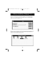
Insert the diskette labeled P27236 in your floppy drive. In the Program
Manager, click on File then click Run. In the space, type in "a:\setup.exe".
Follow the installation instruction prompts. After the setup program is done,
simply double-click on the correct icon to run the port selection program.
6
P73043/F1U127uKIT univ/man.qxd
4/28/00
1:58 PM
Page 7
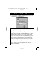
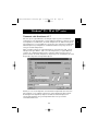
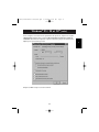
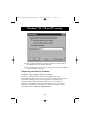
Software installation: MS-DOS
En
To switch port, simply click on the port letter of your choice, and your
computer will be connected to the device on the port chosen.
Software-Installation: MS-DOS
Enter the following at the DOS prompt and press ENTER:
Copy a:\dos\swport.com c:\SWPORT.com
SWPORT.com is a command-line executable. Please follow the syntax for
proper operation:
File Transfer in DOS and WINDOWS® 3.x:
The file transfer feature of the Bitronics switch allows both computers to
connect a if there was a file transfer cable connected between them.
The LED of the corresponding computer port on the Bitronics switch will turn
green. This LED represents the computer you are on now, and is set for file
transfer mode.
Next, the second PC must also perform the same operation. When both sets
of PC LEDs on the Bitronics switch are green, then the computers are ready for
file transfer. At this point, the cables and the Bitronics switch act as if it was a
file transfer cable. You can now run programs such as Windows®‚ Direct Cable
Connection, or LapLink®. Please refer to their user manuals or websites for
information on how to configure their software. Just remember that your
Bitronics switch setup mimics the file transfer cable requirement.
7
P73043/F1U127uKIT univ/man.qxd
4/28/00
1:58 PM
Page 8
Windows® 95 / 98 and NT®
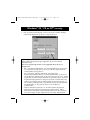
BEFORE YOU INSTALL THE BELKIN BITRONICS SOFTWARE, YOU MUST
FIRST MAKE SURE THAT EACH DEVICE WORKS PROPERLY ON ITS OWN
WITH EACH COMPUTER. DO NOT CONNECT THE BITRONICS SWITCH TO
THE COMPUTERS OR INSTALL THE SOFTWARE UNTIL INSTRUCTED BY
THIS PROCEDURE!
1.
Make sure that the printer port on your computer is set to ECP mode. To
do this, you must go into your computer’s BIOS or CMOS setup.
Instructions on how to do this differs from one computer to the next.
Please consult your computer manufacturer’s manual, tech support, or
website for information on how to do this. Please do not call Belkin Tech
Support regarding this because each computer’s BIOS setup routine is
different. Refer to the Appendices at the end of this manual for
information on several models of computers.
The BIOS setup routine prompt is displayed a few seconds after you turn
on your computer and hear its first beeps. Again, this varies from PC to
PC. Please consult the Appendices and/or your computer manufacturer’s
manual or their tech support for information on how to do this properly.
Usually you will see a message that reads Press DEL to Enter Setup or
Press F2 to Enter Setup. When in the setup program, there may be a
selection for "Integrated Peripherals", or "Peripheral Setup". Then, look
for "Parallel Port Type" or "LPT port type". Change that setting to say
"ECP" or "ECP/EPP". Save your settings then exit. When Windows®
restarts, it may find new hardware, and it may ask you for the Windows®
CD. Be prepared to insert the CD into the computer.
2.
Make sure that the software and drivers for the devices to be shared are
properly installed on all computers.
For instance, if you are sharing a Zip® Drive and a printer between 2
computers, you will need to first connect and install the Zip® Drive drivers
on the first PC. Make sure that the Zip® Drive works perfectly on it, then
repeat the same installation process for the second PC. Then, you will
need to do the same installing the printer’s driver on both PCs as well.
This way, all the PCs have the drivers properly loaded so each one can
access either device without any problems, as if they were connected to
the computer individually.
8
P73043/F1U127uKIT univ/man.qxd
4/28/00
1:58 PM
Page 9
Windows® 95 / 98 and NT® (continued)
En
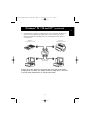
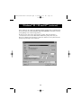
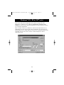
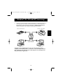
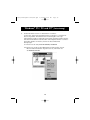
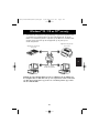
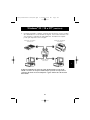
3.
Connect both computers and the devices to be shared to the Bitronics
Switch as shown below. Two cables that connect computers to the
Bitronics switch are included. Take note of which port each device is
connected to:
Device A
connected to Port A
Device B
connected to Port B
These two cables
are included
Connect the power adapter to the power jack on the side of the switch,
and plug it into an outlet. The example shown has a Zip® Drive connected
to Port A and an InkJet printer on Port B of the switch.
9
P73043/F1U127uKIT univ/man.qxd
4/28/00
1:58 PM
Page 10
Windows® 95 / 98 and NT® (continued)
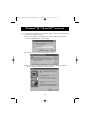
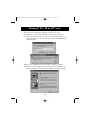
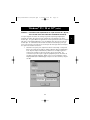
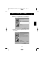
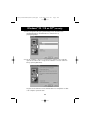
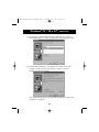
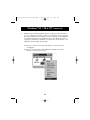
4.
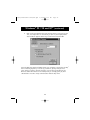
In order for all computers to properly share the devices, the software must
be installed on both computers.
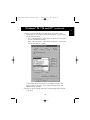
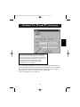
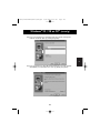
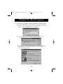
4.1. Insert the disk into your floppy drive. Click on Start, then click Run.
Enter a:\BITRONIX.exe, then click OK.
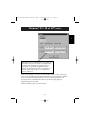
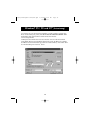
4.2. You will see the following window. Click Setup.
4.3. Close all other running applications so that the software installation
can proceed quickly and smoothly. Click Next.
10
P73043/F1U127uKIT univ/man.qxd
4/28/00
1:58 PM
Page 11
Windows® 95 / 98 and NT® (continued)
En
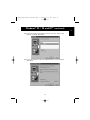
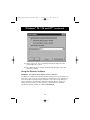
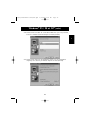
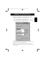
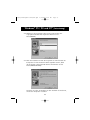
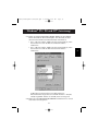
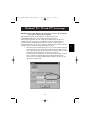
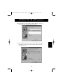
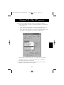
4.4. Select the model of the Bitronics Switch you have, which is the
F1U127 / F1U128. Click Next.
4.5. Select Destination Folder. The default folder is recommended.
Click Next.
11
P73043/F1U127uKIT univ/man.qxd
4/28/00
1:58 PM
Page 12
Windows® 95 / 98 and NT® (continued)
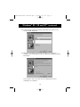
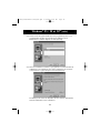
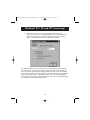
4.6. Select Program Folder. The default, Belkin Bitronics Switch, is the
recommended. Click Next.
4.7. When done installing, the program will ask you to restart your
computer. You must restart in order to activate the software properly.
Click Finish.
Don’t forget to remove the disk from your floppy drive before
restarting your computer!
12
P73043/F1U127uKIT univ/man.qxd
4/28/00
1:58 PM
Page 13
Windows® 95 / 98 and NT® (continued)
En
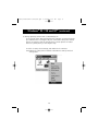
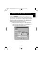
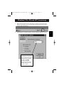
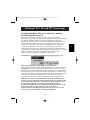
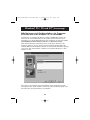
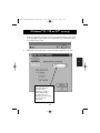
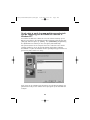
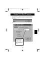
5.
Once your computer has rebooted, the Bitronics icon will appear in
your system tray. This is how you can easily control and configure the
Bitronics Switch.
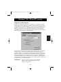
6. Double-click on the icon to open up the setup program:
Select the correct LPT
port the Bitronics
switch is connected to.
If you only have ONE
parallel port (usually
that is the case), leave
this in LPT1.
13
P73043/F1U127uKIT univ/man.qxd
4/28/00
1:58 PM
Page 14
Windows® 95 / 98 and NT® (continued)
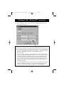
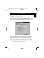
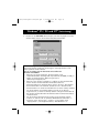
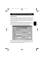
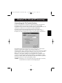
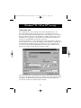
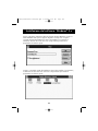
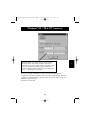
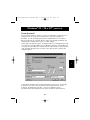
7.
Click on Settings. This is where you tell the software what devices are
connected to each port:
Device Type gives you a pull-down menu showing the types of printers
installed on your computer and other possible parallel device types as well.
Here, you must select the correct type for the device connected to that port.
•
If you are using a device which adds a drive letter to your system (like a
Zip® Drive, CD-ROM, LS-120, etc...), use the Mass Storage
Device setting.
•
If you are using a printer, use the printer driver used for that particular
printer on that port of the Bitronics switch. If it does not show up in this
menu, that means the printer drivers have not been installed. (In that
case, reinstall the printer drivers and repeat this step after rebooting
your computer.) If you have more than one printer installed, make sure
that the correct driver is used for the printer connected to that port on
the Bitronics switch.
•
For any other parallel device, just use Scanner, and change the Display
Name accordingly. For example, if you have a parallel tape drive, use
Scanner for Device Type, then enter Tape Drive in Display Name.
14
P73043/F1U127uKIT univ/man.qxd
4/28/00
1:58 PM
Page 15
Windows® 95 / 98 and NT® (continued)
En
Display Name is a free text field. You can enter
any description here for the attached devices. For
instance, Port A has the Zip® Drive connected and
Port B has the InkJet connected. You can rename
these fields to say "My Zip Drive" and "Color
Printer #2".
In our example, we have a Zip® drive on Port A, so we chose Mass Storage
Device for Port A. And in Port B, we have the Epson printer installed, so we
chose that driver in the Device Type for Port B.
Click OK when finished.
15
P73043/F1U127uKIT univ/man.qxd
4/28/00
1:58 PM
Page 16
Windows® 95 / 98 and NT® (continued)
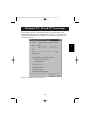
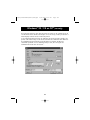
8. Change printer port from LPT1 to AutoSwitch port:
If one or both of the devices being shared is a printer, you must follow the
procedure below to reconfigure the port connected to the printer. If both
devices are printers, then this must be done for both printers. If neither
device is a printer, then you can skip this step.
8.1. Click on Start, select Settings, and double-click on Printers.
8.2. Right-click on the printer installed on the Bitronics switch, and click
on Properties:
16
P73043/F1U127uKIT univ/man.qxd
4/28/00
1:58 PM
Page 17
Windows® 95 / 98 and NT® (continued)
En
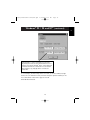
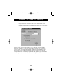
8.3. Click on the Details tab. In the pull-down menu Print to the
following port:, select the correct port this printer is connected to
on the Bitronics switch:
• LPx1 – PA (autoswitch) – Select this if the printer is connected to
Port A of the Bitronics switch.
• LPx1 – PB (autoswitch) – Select this if the printer is connected to
Port B of the Bitronics switch.
In the image above, the printer is connected to Port B of the
Bitronics switch. Therefore, LPx1 – PB (autoswitch) is selected.
When finished, click OK.
8.4. Click on Spool Settings and click on Start printing after last page
is spooled.
17
P73043/F1U127uKIT univ/man.qxd
4/28/00
1:58 PM
Page 18
Windows® 95 / 98 and NT® (continued)
8.5. If Not grayed out, click on Disable bi-directional support for this
printer. Otherwise, ignore.
8.6. Click OK in the Spool Settings window. Click OK again in the main
properties window.
Using the Bitronics Software
EXAMPLE: Two Printers Shared Between Two Computers
The Bitronics Software automatically handles printing chores by directing your
print jobs to the correct port on the Bitronics switch based on the settings you
set in the Printer Properties and the Settings in step 7 previously. When you
print something in any Windows® application (like MS Word or Excel), you
simply select the printer you wish to print to, and the Bitronics software
handles the switching duties. IT IS FULLY AUTOMATIC!
18
P73043/F1U127uKIT univ/man.qxd
4/28/00
1:58 PM
Page 19
Windows® 95 / 98 and NT® (continued)
En
How does it work?
With the Bitronics Software loaded and the ports properly configured for the
printers as shown in step 8 above, when you print in Windows®, the print job
goes to the Bitronics software first. There, the Bitronics software adds a
command in the beginning of the print job telling the Bitronics Switch which
port to send the print job to.
In the example below, the Epson Printer is connected to Port B, as described
in the Where: line. When printing, the Bitronics software tells the Bitronics
switch to switch to Port B first, then allows the print job to go through the
switch, out to Port B, and to the Epson printer.
Then if you wish to print to the second printer, let’s say a LaserJet™ for
example, all you have to do is select that particular printer in the Print dialog
box. Click OK, and the print job is automatically sent to the LaserJet™ printer
on Port A of the Bitronics switch.
19
P73043/F1U127uKIT univ/man.qxd
4/28/00
1:58 PM
Page 20
Windows® 95 / 98 and NT® (continued)
All you have to do is pick your printer, and the software does everything else.
But remember, ALL THE SETTINGS MUST BE CORRECT, otherwise you may
print garbage out of the wrong printer!
Below, the user has chosen the LaserJet™ printer. Here, this printer is
connected to Port A of the AutoSwitch. When the print job is sent, the
Bitronics software tells the Bitronics switch to switch to Port A, then lets the
print job go through to the LaserJet™.
20
P73043/F1U127uKIT univ/man.qxd
4/28/00
1:58 PM
Page 21
Windows® 95 / 98 and NT® (continued)
En
EXAMPLE: Sharing One Printer and a Zip Drive (or any other mass
storage device)
®
When dealing with a mass storage device (devices that add a drive letter to
your system like E:) such as a Zip® Drive, the Bitronics Software in the system
tray must be configured so that the Bitronics switch is defaulted to the Port
attached to the Zip® Drive. It is necessary for the switch to always remain
connected to the Zip® Drive so that any time you access that drive, you will
always be connected, and not receive error messages:
1.
Make sure that the port that connects to the Zip® Drive is set to
Mass Storage Device in Settings. See Step 7 above for more info.
The image below shows the Zip® Drive is connected to Port A, and
that the device type is Mass Storage Device. Type anything you
want in Display Name. Click OK when finished.
21
P73043/F1U127uKIT univ/man.qxd
4/28/00
1:58 PM
Page 22
Windows® 95 / 98 and NT® (continued)
2.
Click on the port that has the mass storage device connected. In this
case, it is a Zip® Drive on Port A. As you can see, the Display Name
entered above appears below as you had entered it. Click OK.
Now, the Bitronics switch will always keep your computer connected to the Zip®
Drive. That way, anytime you access it, you will not get any strange errors.
Then, when you print to the Ink Jet Printer on Port B (as shown above), the
Bitronics switch will switch to Port B temporarily to send the print job, then
switch back to Port A to keep communication with the Zip® Drive.
22
P73043/F1U127uKIT univ/man.qxd
4/28/00
1:58 PM
Page 23
Windows® 95 / 98 and NT® (continued)
En
Visual Feedback – How do I know what port I am on?
When the Bitronics switch is in its normal scanning mode, the LEDs are
moving back and forth across the computer ports. To see the software in
action, simply press the COMPUTER button so you can see a computer
port’s connection. Press the COMPUTER port until the LEDs around 1 are lit
up, and you will see which device port it is currently connected to. If it is in
File Transfer mode, the computer port LEDs are green, and neither device
port LEDs will be lit. Then, click on the Bitronics software icon in the taskbar
and change ports. You will see the LED of the Bitronics switch to the port
you chose.
Using any other parallel device (not printers or mass
storage devices) with a printer
When dealing with other parallel port devices, they are set as Scanners in
the Settings (step 7 above). Examples of these are scanners, parallel port
cameras, and tape drives. When you need access to this device, simply
single-click on the Bitronics system tray icon, and select the device you wish
to use. A check mark will appear showing which device is connected. For
example, we have a scanner and a printer on the Bitronics switch:
You will be connected to the scanner device indefinitely. But let us say
you wish to print to the InkJet printer, the software will again
automatically switch to the port that has the printer and send the print
job. However, the switch will remain connected to the printer - it will not
change back to the Scanner, unlike the mass storage device mentioned
previously. This means that you have to use this method to switch to the
scanner each time you need to use it.
23
P73043/F1U127uKIT univ/man.qxd
4/28/00
1:58 PM
Page 24
Windows® 95 / 98 and NT® (continued)
If no printers are installed
If no printers are installed, the Settings type (see step 7) for each device must
be set either for Mass Storage Device (if the device adds a drive letter to your
system), or Scanner (for all other types of devices).
The Bitronics software may not function properly in some systems if there is no
Default Printer set. To do this, add a printer using the Add Printer Wizard
(click Start, select Settings, double-click on Printers), and just use the
Generic/Text Only driver. Remember to use Local Printer and LPT1 when the
wizard asks you. This will then be set as your default printer, so that the
Bitronics software can work properly.
Removing and Adding the Bitronics Switch Icon from
the System Tray
•
To remove the icon, simply right click on it, and answer Yes to
the prompt.
•
To reload the icon back into the system tray, click on Start, select
Programs, select Belkin Bitronics Switch and select
AutoSwitch-Multi PCs.
ADVANCED USER TIP:
If you are using devices with pass-through ports (like Zip® Drives and
Scanners), you can connect a printer to the pass-through port and use the
other device port on the Bitronics switch to connect to another device. Just be
sure that the printer driver has its Port set to the correct device port. For
example, if you wish to share 2 printers, 1 Zip® Drive and 1 scanner between 2
computers, connect the Zip® Drive to Port A, the Scanner to Port B, the first
printer to the pass-through of the Zip® Drive, and the second printer to the
pass-through of the scanner. In the Bitronics software, set Port A to Mass
Storage Device, and Port B to Scanner. Then in the Printer Properties/ details,
set the Print to the following Port to LPx1- PA (auto switch) for the first printer,
and LPx1- PB (auto switch) for the second printer. In general, only printers can
be connected to pass-through ports.
24
P73043/F1U127uKIT univ/man.qxd
4/28/00
1:58 PM
Page 25
Windows® 95 / 98 and NT® (continued)
En
Using the File Transfer Feature
The file transfer feature of the Bitronics switch allows both computers to
connect as if there were a file transfer cable connected between them. To
do this, double-click on the Bitronics switch system tray icon, click on File
Transfer, and click OK. The LED of the corresponding computer port on the
Bitronics switch will turn green. This LED represents the computer you are
on now is set for file transfer mode.
Next, the second PC must also perform the same operation. When both sets
of PC LEDs on the Bitronics switch are green, then the computers are ready
for file transfer. At this point, the cables and the Bitronics switch act as if it
were a file transfer cable. You can now run programs such as Windows®
Direct Cable Connection, or LapLink®. Please refer to their user manuals or
websites for information on how to configure their software. Just remember
that your Bitronics switch setup mimics the file transfer cable requirement.
NOTE: If you change the ports manually using the buttons, the changes
made will not be reflected in the software.
25
P73043/F1U127uKIT univ/man.qxd
4/28/00
1:58 PM
Page 26
Windows® 95 / 98 and NT® (continued)
Usage in Windows NT®
In Windows NT®, you can perform the same installation as in the Windows® 95/
98 procedure above. Make sure the power supply is connected to the
Bitronics switch, otherwise, there may be a significant delay in the processing
of requests from NT®-based machines.
The Printer properties in Windows NT® is slightly different. After installing the
software and restarting the computer, go to the printer properties and select
the Ports tab. To find the correct ports to be used with the Bitronics switch,
you must scroll down the list until the LPx1: PA (autoswitch) comes up. Put a
checkmark on the port that connects to the printer. In this case, it is Port A on
the Bitronics switch:
26
P73043/F1U127uKIT univ/man.qxd
4/28/00
1:58 PM
Page 27
Windows® 95 / 98 and NT® (continued)
En
To set the spool settings correctly, click on the SCHEDULING tab. Make sure
"Start printing after last page is spooled" is selected. Also, set "Priority" to
highest:
Click OK when done.
27
P73043/F1U127uKIT univ/man.qxd
4/28/00
1:58 PM
Page 28
Windows® 95 / 98 and NT® (continued)
If you are still having problems using the BITRONIX.exe
software in Windows NT®:
First UNINSTALL the Bitronics software. You can do this by right-clicking on
the taskbar icon and answering YES to the prompt. Then, click on START,
PROGRAMS, BELKIN BITRONICS SWITCH, then UNINSTALLSHIELD.
After restarting your computer, you can install the older NT version of the
software located in the second disk (part# P72736). During the installation, it
will ask you the model number. Please select "Auto Switch 2-2 / 4-2":
This version of the software is not fully automatic in printer selection. It
requires the user to select ports each time through the taskbar icon.
28
P73043/F1U127uKIT univ/man.qxd
4/28/00
1:58 PM
Page 29
Appendix
En
Changing your PC’s parallel port mode to ECP
Changing your computer’s parallel port mode to ECP increases speed and reliability of
data transfers with the Bitronics Switches. Below are the steps on changing the settings
on certain computers. Do this on all the computers connected to the switch. If your
computer is not listed here, please check their website, or call their technical support.
Please do not call Belkin Tech Support on this particular issue.
ACER
1.
2.
3.
4.
While the computer is booting, follow the directions on the screen: To enter
Setup, press CTRL+ALT+ESC.
Follow the legend on how to scroll through the options.
When you reach the option Parallel Port Mode, choose ECP.
Follow the legend directions to save the setting and exit Setup.
AST
1.
2.
3.
4.
While the computer is booting, follow the directions on the screen: To enter
Setup, press CTRL+ALT+ESC. (If you have a 486 computer, the directions might
say press CTRL+ALT+DEL).
Follow the legend directions on how to scroll through the options.
When you reach the Parallel Port Mode option, choose the mode with the
highest performance (e.g. ECP).
Follow the legend directions to save the setting and exit setup.
Generic clone computer
1.
2.
3.
4.
5.
6.
7.
Restart the computer and press F1 during the startup.
Use an arrow key to select the Advance menu item.
Use an arrow key to select the parallel port setting and the mode field.
Press ENTER to get the mode list.
Select the mode with the highest performance (e.g. ECP) and then press ENTER.
Press F10 to save the BIOS (basic input/output system) changes.
Press ENTER to close the BIOS settings window.
Dell
1.
2.
While the computer is booting, follow the directions on the screen: To enter
Setup, press DEL. (If you have a 486 computer, the directions might say press F2.)
Press ALT+P and choose Parallel Mode.
29
P73043/F1U127uKIT univ/man.qxd
4/28/00
1:58 PM
Page 30
Appendix (continued)
3.
4.
There should be a list of modes available. Choose the mode with the highest
performance (e.g. ECP).
Follow the legend directions to save the setting and exit Setup.
Gateway 2000
1.
2.
3.
4.
5.
While the computer is booting, follow the directions on the screen: To enter
Setup, press F1.
Select Advanced from the menu bar.
Select Integrated Peripherals.
Following the legend directions, select ECP as the parallel port mode.
Follow the legend directions to save the setting and exit Setup.
Hewlett-Packard
Steps for HP Pavillion PC Models
1.
2.
3.
4.
5.
At the HP Blue Screen, press F1 to enter Setup.
Select Advanced from the menu bar.
Following the legend directions, select Peripheral Configuration and then use the
arrow-down key to move to Parallel Port Mode.
Select the mode with the highest performance (e.g. ECP).
Follow the legend directions to save the setting and exit Setup.
Steps for HP Vectra PC Series
1.
2.
3.
4.
5.
While the computer is booting, follow the directions on the screen: Press F2 to
Enter Setup. This is displayed at the bottom of the Hewlett Packard System
Hardware Test screen.
Use the arrow keys to highlight Parallel Port Mode.
Follow the legend directions on how to change the options.
Set the port mode with the highest performance (e.g. ECP).
Follow the legend directions to save the setting and exit Setup.
Steps for HP Vectra 500 PC Series
1.
2.
3.
4.
5.
While the computer is booting, follow the directions on the screen: Press F2 to
Enter Setup. This is displayed at the bottom of the Hewlett Packard System
Hardware Test screen.
Use the arrow keys to highlight Parallel Port Mode.
Follow the legend directions on how to change the options.
Set the port mode with the highest performance (e.g. ECP).
Follow the legend directions to save the setting and exit Setup.
30
P73043/F1U127uKIT univ/man.qxd
4/28/00
1:58 PM
Page 31
Appendix (continued)
En
Steps for HP OmniBook 5000 and 5500 PCs
1.
2.
3.
4.
5.
While the computer is booting, follow the directions on the screen: Press F2 to
Enter Setup. This is displayed at the bottom of the Hewlett Packard System
Hardware Test screen.
Use the arrow keys to highlight Parallel Port Mode.
Follow the legend directions on how to change the options while selecting the
parallel port mode with the highest performance (e.g. ECP).
Follow the legend directions to save the setting and exit Setup.
Add the Ecpon.com program to the computer's Autoexec.bat file. You can find
this file on the compact disc or on Disk 1 of the disk set.
IBM Aptiva
General Steps
1.
2.
3.
4.
While the computer is booting, follow the directions on the screen: Press F1 to
enter Setup.
Follow the legend on how to scroll through the setup options until you reach
Input/Output Ports.
Choose the mode with the highest performance (e.g. ECP).
Follow the legend directions to save and exit Setup.
Steps for IBM Aptiva 2176-C33, IBM BIOS v BSTUS4B
NOTE: The steps for this computer are not included in the document received in
the box.
1.
2.
3.
4.
5.
6.
While the computer is booting, follow the directions on the screen: Press F1 to
enter Setup.
Follow the legend on how to scroll through the setup options until you reach
Input/Output Ports.
Select Parallel Port Mode.
Select ECP.
Press ESC twice.
Press ENTER to save the setting and exit Setup.
Micron
General Steps
1
2.
3.
While the computer is booting, follow the directions on the screen: Press F2 to
enter Setup.
Select Advanced from the menu bar.
Follow the legend directions to select Integrated Peripherals.
31
P73043/F1U127uKIT univ/man.qxd
4/28/00
1:58 PM
Page 32
Appendix (continued)
4.
5.
6.
Use the arrow-down key to select LPT Mode.
Select the parallel port mode with the highest performance (e.g. ECP).
Follow the legend directions to save the setting and exit Setup.
Steps for the Millennium, Phoenix BIOS v 4.05
NOTE: The steps for this computer are not included in the document received in
the box.
1.
2.
3.
4.
While the computer is booting, follow the directions on the screen: Press F2 to
enter Setup.
Go to Connectivity.
Change Port from AT to ECP.
Select PS/2.
Packard Bell
General Steps
1
2.
3.
4.
5.
While the computer is booting, follow the directions on the screen: Press F2 to
Enter Setup. (It might be F1 on some models.)
Select Advanced from the menu bar.
Follow the legend directions to select Integrated Peripherals (or Peripheral
Configuration on some models).
Choose the parallel port mode with the highest performance (e.g. ECP).
Follow the legend directions to save the setting and exit Setup.
Steps for the Force 443 CD, AMBIOS BIOS v 1.00.12.1313oe
1
While the computer is booting, follow the directions on the screen: Press F1 to
Enter Setup.
2. Select Advanced from the menu bar.
3. Use the down-arrow key to select Peripheral Config and then
press ENTER.
4. Use the down-arrow key to select Parallel Port Mode and then
press ENTER.
5. Use the down-arrow key to select Extended (originally Compatible) and then
press ENTER.
6. Press F10 to save the setting.
Sony
Models PCV-70/90/100/120:
1.
2.
3.
4.
Restart your computer.
During the first black and white Sony screen, press F3 to enter the
boot screen.
Press F1 to enter the BIOS Setup.
Use right arrow to reach the Advanced menu.
32
P73043/F1U127uKIT univ/man.qxd
4/28/00
1:58 PM
Page 33
Appendix (continued)
En
5.
6.
7.
8.
9.
Scroll down and highlight Peripheral Configuration and press ENTER.
Scroll down and highlight Parallel Port Type. The default setting is Compatible.
Press ENTER.
Select ECP and press ENTER.
Press ESC twice to get to the Exit screen.
Press ENTER twice to Exit Saving Changes. The system will restart
into Windows®.
Models PCV-130/150:
1.
2.
Restart your computer.
During the first black and white Sony screen, press F3 to enter the
boot screen.
3. Press F1 to enter the BIOS Setup.
4. Use right arrow to reach the Advanced menu.
5. Scroll down and highlight Peripheral Configuration and press ENTER.
6. Scroll down and highlight Mode. The default setting is ECP.
Press ENTER.
7. Select ECP. Press ENTER.
8. Scroll to Parallel Port and press ENTER.
9. Select Enabled and press ENTER.
10. Press ESC twice to get to the Exit screen.
11. Press ENTER twice to Exit Saving Changes. The system will restart
into Windows®.
Models PCV-200/210/220/230/240:
1.
2.
Restart your computer.
During the first black and white Sony screen, press F3 to enter the
boot screen.
3. Press F1 to enter the BIOS Setup.
4. Use right arrow to reach the Advanced menu.
5. Scroll down and highlight Peripheral Configuration and press ENTER.
6. Scroll down and highlight Mode. The default setting is ECP.
Press ENTER.
7. Select either ECP. Press ENTER.
8. Scroll to Parallel Port and press ENTER.
9. Select Enabled and press ENTER.
10. Press F10 to save these changes, confirm and exit. The system will restart
into Windows®.
Sony PCG-705/707/717/719 Notebooks:
1.
2.
3.
4.
In Windows® 95, open the Start Menu.
Select Sony Folder.
Select Sony Utilities.
Select Sony Notebook Setup.
33
P73043/F1U127uKIT univ/man.qxd
4/28/00
1:58 PM
Page 34
Appendix (continued)
5.
6.
7.
8.
Select the Printer/FDD tab.
Make sure Use as printer connector is selected and choose the desired port
mode required by the printer. There are three options available on this screen:
1. Normal (Output only)
2. Bi-directional (default)
3. ECP (requires IEEE 1284 printer/parallel cable)
Select ECP and click OK to save results and close the window.
Click Yes to restart the computer.
NOTE: Changes made in the Sony Notebook Utility are also made in
the BIOS.
Sony PCG-729:
1.
2.
3.
4.
5.
6.
7.
In Windows® 95, open the Start Menu.
Select Tool Center.
Select Sony Notebook Setup.
Select the Printer/FDD tab.
Make sure Use as printer connector is selected and choose the desired port
mode required by the printer. There are three options available on this screen:
1. Normal (Output only)
2. Bi-directional (default)
3. ECP (requires IEEE 1284 printer/parallel cable)
Select ECP and click OK to save results and close the window.
Click Yes to restart the computer.
NOTE: Changes made in the Sony Notebook Utility are also made in
the BIOS.
34
P73043/F1U127uKIT univ/man.qxd
4/28/00
1:58 PM
Page 35
Information
En
FCC Statement
DECLARATION OF CONFORMITY WITH FCC RULES FOR
ELECTROMAGNETIC COMPATIBILITY
We, Belkin Components, of 501 West Walnut Street, Compton CA 90220, declare under our sole
responsibility that the product:
F1U127-KIT
to which this declaration relates:
Complies with Part 15 of the FCC Rules. Operation is subject to the following two conditions: (1)
this device may not cause harmful interference, and (2) this device must accept any interference
received, including interference that may cause undesired operation.
CE Declaration of Conformity
We, Belkin Components, declare under our sole responsibility that the F1U127-KIT, to which this declaration relates, is
in conformity with Generic Emissions Standard EN50081-1 and with Generic Immunity Standard EN50082-1 1992.
Belkin Components One Year Product Warranty
Belkin Components warrants this product against defects in materials and workmanship for one year. If a defect is
discovered, Belkin will, at its option, repair or replace the product at no charge provided it is returned during the
warranty period, with transportation charges prepaid, to the authorized Belkin dealer from whom you purchased the
product. Proof of purchase may be required.
This warranty does not apply if the product has been damaged by accident, abuse, misuse, or misapplication; if the
product has been modified without the written permission of Belkin; or if any Belkin serial number has been removed
or defaced.
THE WARRANTY AND REMEDIES SET FORTH ABOVE ARE EXCLUSIVE IN LIEU OF ALL OTHERS, WHETHER
ORAL OR WRITTEN, EXPRESSED OR IMPLIED. BELKIN SPECIFICALLY DISCLAIMS ANY AND ALL IMPLIED
WARRANTIES, INCLUDING, WITHOUT LIMITATION, WARRANTIES OF MERCHANTABILITY AND FITNESS FOR A
PARTICULAR PURPOSE.
No Belkin dealer, agent, or employee is authorized to make any modification, extension, or addition to this warranty.
BELKIN IS NOT RESPONSIBLE FOR SPECIAL, INCIDENTAL, OR CONSEQUENTIAL DAMAGES RESULTING FROM
ANY BREACH OF WARRANTY, OR UNDER ANY OTHER LEGAL THEORY, INCLUDING BUT NOT LIMITED TO LOST
PROFITS, DOWNTIME, GOODWILL, DAMAGE TO OR REPROGRAMMING, OR REPRODUCING ANY PROGRAM OR
DATA STORED IN OR USED WITH BELKIN PRODUCTS.
belkin.com
Belkin Components
Belkin Components, Ltd.
Belkin Components B.V.
501 West Walnut Street
Compton • CA • 90220 • USA
Tel: 310.898.1100
Fax: 310.898.1111
Unit 13 • Gatelodge Close • Round Spinney
Northampton • Northants • NN3 8RX • UK
Tel: +44 (0) 1604678300
Fax: +44 (0) 1604678330
Diamantlaan 8 • 2132 WV
Hoofddorp • The Netherlands
Tel: +31 (0) 235698765
Fax: +31 (0) 235612694
© 2000 Belkin Components. All rights reserved. All trade names are registered trademarks of respective manufacturers listed.
P73043/F1U127fKIT univ/man.qxd
4/28/00
2:00 PM
Page 37
Introduction
Nous vous remercions d’avoir choisi le kit du commutateur Bitronics DualBus
de Belkin Components. Vos collègues et vous-même pouvez désormais
partager deux périphériques parallèles différents ou sélectionner l’un d’entre
eux depuis votre ordinateur. En outre, si vous utilisez Windows® 95 / 98 ou
NT®, vous pourrez également profiter des avantages offerts par le logiciel
Bitronics qui vous permet d’imprimer automatiquement même si vous
possédez plus d’une imprimante !
Caractéristiques
•
•
•
•
•
•
Permet à deux ordinateurs d’accéder à deux périphériques parallèles de
façon indépendante et simultanée
Le logiciel de pilote d’imprimante Port Virtuel vous permet de
sélectionner automatiquement l’imprimante sous Windows® 95/98 et NT
Transfert de fichiers entre deux PC compatibles avec Windows® Direct
Cable Connection, LapLink® et DOS Interlink™
Comprend deux câbles compatibles IEEE 1284 d’1,80 m permettant de
raccorder les ordinateurs
Adaptateur de courant fourni
Délai réglable
Contenu de l’emballage :
Autocommutateur Bitronics DualBus, 2-2
Adaptateur de courant, 9VDC, 600mA
2 câbles compatibles IEEE 1284
Guide de l’utilisateur
Carte de garantie
F1U127f
F1D065-PWR-IT
F2A047f06
P73043
P53324
Autres pièces nécessaires (le cas échéant)
•
Câble d’imprimante IEEE 1284, pièce Belkin n° F2A046fXX. Vous aurez
besoin de ce câble pour raccorder une imprimante à l’autocommutateur.
Les câbles actuels de votre imprimante fonctionneront peut-être mais
nous vous conseillons d’utiliser des câbles compatibles IEEE.
•
Câble de périphérique IEEE 1284, pièce Belkin n° F2A047fXX. Vous aurez
besoin de ce câble pour raccorder un ordinateur à l’autocommutateur.
REMARQUE : « XX » indique la longueur du câble en pieds.
37
Fr
P73043/F1U127fKIT univ/man.qxd
4/28/00
2:00 PM
Page 38
Spécifications techniques
Normes compatibles :
Norme de communication port parallèle
Électrique :
Tension électrique à l’entrée
Courant maximum à l’entrée
Consommation maximale de courant
Dissipation maximale de chaleur :
Dimensions :
Largeur :
Hauteur :
Profondeur :
Weight :
Température de stockage :
Température de travail :
Humidité relative :
IEEE 1284-1994
9VDC
600mA
5,4W
0,31 BTU / min
17,8cm
9,5cm
3,2cm
202 g
de -10°C à 50°C
de 0°C à 40°C
de 0 à 95%,
pas de condensation
38
P73043/F1U127fKIT univ/man.qxd
4/28/00
2:00 PM
Page 39
Détails relatifs au produit
Voyants indiquant l’activité
des périphériques.
Connecteur – Périphérique A
Connecteur – Périphérique B
Fr
Prise courant
continu (côté)
Connecteur – PC2
Connecteur – PC1
PC activity LEDs
Bouton de l’ordinateur
Bouton de l’imprimante
Positionnement des interrupteurs DIP
(situés sous le commutateur) :
ON
DIP
SW1 : Réinitialisation du commutateur
Pour la réinitialisation : OFF→ON→OFF
1
2
3 4
ON : en haut. SW4 n’est pas utilisé.
SW2 et SW3 : Fixation du délai
Le délai (TimeOut) correspond au laps de temps durant lequel le commutateur
reste bloqué sur un port de PC après le transfert de données. Optez pour un
délai plus long lorsque vous raccordez des scanners, unités de stockage à
grande capacité et pour des impressions volumineuses.
SW2
SW3
Délai
ON
ON
5 secondes
ON
OFF
10 secondes
OFF
ON
20 secondes
OFF
OFF
40 secondes
39
Recommandé
P73043/F1U127fKIT univ/man.qxd
4/28/00
2:00 PM
Page 40
Mode manuel et contrôle du port
En mode manuel, vous pouvez sélectionner un port manuellement grâce aux
boutons du commutateur Bitronics. Vous pouvez également utiliser ce mode
en lien avec le logiciel pour voir votre commutateur en action !
•
Appuyez sur COMPUTER (Ordinateur) pour sélectionner le port de
l’ordinateur que vous souhaitez configurer ou contrôler. Pour sélectionner
l’ordinateur relié au port 1, appuyez sur le bouton COMPUTER jusqu’à ce
que le voyant lumineux du Port 1 soit rouge ou vert.
•
Appuyez sur le bouton PRINTER (Imprimante) jusqu’à ce que s’allume
le voyant lumineux du port du périphérique approprié que vous
souhaitez utiliser.
Par exemple, si vous voulez
que l’ordinateur 2 utilise le
périphérique sur le port B,
appuyez sur le bouton
COMPUTER jusqu’à ce que
s’allume le voyant lumineux
« 2 ». Appuyez ensuite sur
le bouton PRINTER jusqu’à
ce que s’allume le voyant
lumineux « B ».
Bouton de l’imprimante
Bouton de l’ordinateur
Pour utiliser le mode de transfert de fichier, appuyez sur le bouton PRINTER
jusqu’à ce que le voyant lumineux du port de l’ordinateur devienne vert.
Lorsque le voyant devient vert, le port est prêt pour le mode de transfert de
fichiers. Pour que ce mode soit opérationnel pour les deux ordinateurs, les
deux ports d’ordinateurs doivent être configurés pour le mode de transfert de
fichiers ñ (les voyants jouxtant 1 et 2 sont alors verts). Pour de plus amples
informations sur le transfert de fichiers, cf. page 26.
REMARQUE : Si vous modifiez les ports manuellement grâce aux boutons, les
modifications apportées ne seront pas reflétées dans
le logiciel.
40
P73043/F1U127fKIT univ/man.qxd
4/28/00
2:00 PM
Page 41
Sélection du mode de fonctionnement
Windows® 3.x . . . . . . . . . . . . . . . . . . . . . . . . . . . . . . . . . . . . . . . . . .Page 40
MS-DOS
. . . . . . . . . . . . . . . . . . . . . . . . . . . . . . . . . . . . . . . . . . . . .Page 41
Fr
Windows 95 / 98 et NT
®
®
. . . . . . . . . . . . . . . . . . . . . . . . . . . . . . . . .Page 42
REMARQUE : Lorsque vous installez le logiciel sur n’importe quel système
d’exploitation, le logiciel doit être installé sur tous les
ordinateurs raccordés au commutateur Bitronics afin que
chaque machine puisse dûment commander le commutateur.
41
P73043/F1U127fKIT univ/man.qxd
4/28/00
2:00 PM
Page 42
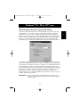
Installation du logiciel : Windows® 3.x
Insérez la disquette portant la référence P27236 dans votre lecteur de
disquettes. Dans le gestionnaire de programmes, cliquez sur FICHIER, puis sur
EXÉCUTER. Dans la case, tapez "a:\setup.exe":
Suivez les instructions relatives à l’installation. Une fois le programme
d’installation terminé, il vous suffit de double cliquer sur l’icône appropriée
pour lancer le programme de sélection du port :
42
P73043/F1U127fKIT univ/man.qxd
4/28/00
2:00 PM
Page 43
Installation du logiciel : MS-DOS
Pour changer de port, il vous suffit de cliquer sur la lettre du port de votre
choix et votre ordinateur sera relié au périphérique du port choisi :
Fr
Installation du logiciel : MS-DOS
Tapez la commande suivante à l’invite DOS et appuyez sur ENTER :
copy a:\dos\swport.com c:\SWPORT.com.
Il s’agit d’une ligne de commande exécutable. Veuillez respecter la syntaxe
afin que la commande fonctionne :
Transfert de fichier sous DOS et WINDOWS® 3.x:
La fonction de transfert de fichier du commutateur Bitronics permet de
connecter les deux ordinateurs comme s’ils étaient reliés entre eux par un
câble de transfert de fichier. Le voyant lumineux du port de l’ordinateur
correspondant (situé sur le commutateur Bitronics), devient alors vert. Ce
voyant lumineux représente l’ordinateur auquel vous êtes actuellement relié et
qui est paramétré pour le mode de transfert de fichiers.
Le deuxième PC doit effectuer ensuite la même opération. Lorsque les deux
séries de voyants lumineux des PC (sur le commutateur Bitronics) sont verts,
cela signifie que les ordinateurs sont prêts pour le transfert de fichiers. A ce
moment là, les câbles et le commutateur Bitronics font office de câble de
transfert de fichiers. Vous pouvez maintenant exécuter des programmes tels
que Windows® Direct Cable Connection ou LapLink®. Pour savoir comment
configurer leur logiciel, veuillez vous référer à leurs modes d’emploi ou aux
sites Internet correspondants. Souvenez-vous simplement que votre
commutateur Bitronics et les câbles fonctionnent comme si vous aviez un câble
de transfert de fichiers.
43
P73043/F1U127fKIT univ/man.qxd
4/28/00
2:00 PM
Page 44
Windows® 95 / 98 et NT®
AVANT D’INSTALLER LE LOGICIEL BITRONICS DE BELKIN, VOUS DEVEZ
VOUS VERIFIER QUE CHAQUE PERIPHERIQUE FONCTIONNE CORRECTEMENT INDIVIDUELLEMENT AVEC CHAQUE ORDINATEUR. NE RACCORDEZ
PAS LE COMMUTATEUR BITRONICS AUX ORDINATEURS ET N’INSTALLEZ
PAS LE LOGICIEL TANT QUE CE MODE D’EMPLOI NE VOUS INVITE
PAS A LE FAIRE !
1.
Vérifiez que le port imprimante de votre ordinateur est positionné sur le
mode ECP. Pour ce faire, vous devez accéder au programme d’initialisation
du système BIOS ou CMOS de votre ordinateur. La marche à suivre dépend
de l’ordinateur. Veuillez consulter le manuel, le support technique ou le site
web du fabricant de votre ordinateur pour savoir comment procéder. Nous
vous remercions de ne pas appeler le support technique de Belkin à ce
sujet car le programme d’initialisation BIOS diffère selon les ordinateurs.
Pour de plus amples informations sur plusieurs modèles d’ordinateurs,
veuillez vous reporter aux annexes figurant à la fin du présent manuel.
Quelques secondes après avoir allumé l’ordinateur et entendu les premiers
bips, vous voyez apparaître l’invite du programme d’initialisation BIOS. Une
fois encore, ceci varie d’un PC à l’autre. Veuillez consulter les annexes, le
mode d’emploi ou le support technique du fabricant de votre ordinateur
pour connaître la marche à suivre. Vous voyez généralement apparaître un
message disant « PRESS DELL TO Enter Setup » (Appuyez sur DEL pour
accéder à l’écran Setup) ou « PRESS F2 TO Enter Setup » (Appuyez sur sF2
pour accéder à l’écran Setup). Une fois dans le programme Setup, vous
verrez peut-être apparaître une sélection pour Integrated Peripherals
(Périphériques intégrés) ou Peripheral Setup (Installation de périphériques).
Cherchez ensuite Parallel Port Type (Type de port parallèle) ou LPT PORT
Type (Type de port LPT). Modifiez ce paramètre afin d’avoir ECP ou ECP /
EPP. Enregistrez ces paramètres et quittez cet écran. En redémarrant, il se
peut que Windows® détecte un nouveau matériel et vous demande le CD
Windows®. Soyez prêt à insérer le CD dans l’ordinateur.
2.
Assurez-vous que le logiciel et les pilotes des périphériques à partager sont
dûment installés sur tous les ordinateurs.
Ainsi, si vous partagez un lecteur Zip® et une imprimante entre deux
ordinateurs, vous devrez d’abord raccorder et installer les pilotes du lecteur
Zip® sur le premier PC. Vérifiez que le lecteur Zip® fonctionne parfaitement
sur ce PC et recommencez le même processus d’installation pour le
deuxième PC. Vous devrez ensuite installer le pilote de l’imprimante sur les
deux PC également. Ainsi, tous les pilotes sont correctement chargés sur les
PC de sorte que chaque PC peut accéder sans problème à n’importe quel
périphérique, comme s’ils étaient connectés à l’ordinateur individuellement.
44
P73043/F1U127fKIT univ/man.qxd
4/28/00
2:00 PM
Page 45
Windows® 95 / 98 et NT® (suite)
3.
Raccordez les deux ordinateurs et les périphériques à partager au
commutateur Bitronics comme indiqué ci-dessous. Deux câbles raccordant
les ordinateurs au Bitronics sont fournis. Notez à quel port chaque
périphérique est raccordé :
Fr
Périphérique A relié au
port A
Périphérique B relié au
port B
Ces deux câbles ne
sont pas fournis
Raccordez l’adaptateur de courant à la prise située sur le côté du
commutateur et branchez le dans une prise de courant. L’exemple
ci-dessous montre un lecteur Zip® raccordé au port A et une imprimante à
jet d’encre raccordée au port B du commutateur.
45
P73043/F1U127fKIT univ/man.qxd
4/28/00
2:00 PM
Page 46
Windows® 95 / 98 et NT® (suite)
4.
Afin que tous les ordinateurs partagent comme il se doit les
périphériques, le logiciel doit être installé sur les deux ordinateurs.
4.1. Insérez la disquette dans votre lecteur de disquettes. Cliquez sur
Start (Démarrer), puis sur Run (Exécuter). Tapez a:\BITRONIX.exe et
cliquez sur OK.
4.2. Vous verrez apparaître la fenêtre suivante. Cliquez sur Setup.
4.3. Fermez toutes les applications afin de poursuivre l’installation du
logiciel rapidement et sans problème. Appuyez sur Next (Suivant).
46
P73043/F1U127fKIT univ/man.qxd
4/28/00
2:00 PM
Page 47
Windows® 95 / 98 et NT® (suite)
4.4. Sélectionnez le modèle de commutateur Bitronics que vous possédez,
à savoir le F1U127 / F1U128. Cliquez sur Next (Suivant).
Fr
4.5. Sélectionnez un dossier de destination. Nous vous recommandons
d’opter pour le dossier par défaut. Cliquez sur Next (Suivant).
47
P73043/F1U127fKIT univ/man.qxd
4/28/00
2:00 PM
Page 48
Windows® 95 / 98 et NT® (suite)
4.6. Sélectionnez leProgram Folder (Dossier programme). Nous vous
recommandons d’opter pour la valeur par défaut, à savoir
Belkin Bitronics Switch. Cliquez sur Next (Suivant).
4.7. Une fois l’installation terminée, le programme vous demandera de
redémarrer votre ordinateur. Vous devez redémarrer pour activer
correctement le logiciel. Cliquez sur Finish (Terminer).
N’oubliez pas de retirer la disquette de votre lecteur de disquette
avant de redémarrer votre ordinateur !
48
P73043/F1U127fKIT univ/man.qxd
4/28/00
2:00 PM
Page 49
Windows® 95 / 98 et NT® (suite)
5.
Une fois que vous avez redémarré l’ordinateur, l’icône Bitronics apparaît
sur l’écran système. Vous pouvez commander et configurer aisément le
commutateur Bitronics en procédant comme suit :
Fr
6. Double-cliquez sur l’icône pour ouvrir le programme d’installation :
Sélectionnez le port
LPT approprié auquel
est raccordé le
commutateur Bitronics.
Si vous n’avez qu’UN
SEUL port parallèle (ce
qui est généralement le
cas), laissez LPT1.
49
P73043/F1U127fKIT univ/man.qxd
4/28/00
2:00 PM
Page 50
Windows® 95 / 98 et NT® (suite)
7.
Cliquez sur Settings (Paramètres). Vous devez indiquer ici au logiciel quels
périphériques sont raccordés à chaque port :
Device Type (Type de périphériques) fait apparaître un menu déroulant
répertoriant les types d’imprimantes installés sur votre ordinateur ainsi que
d’autres types de périphériques parallèles possibles.
Ici, vous devez sélectionner le type approprié pour le périphérique
relié à ce port.
• Si vous utilisez un périphérique qui ajoute une lettre de lecteur à votre
système (tel qu’un lecteur Zip®, un lecteur de CD-ROM, LS-120, etc.), utilisez
le paramètre Mass Storage Device (unité de stockage à grande capacité).
• Si vous utilisez une imprimante, utilisez le pilote d’imprimante utilisé pour
cette imprimante sur ce port du commutateur Bitronics. Si cela n’apparaît
pas dans ce menu, cela signifie que les pilotes de l’imprimante n’ont pas
encore été installés. (Auquel cas, réinstallez les pilotes d’imprimante et
répétez cette étape après avoir réinitialisé votre ordinateur). Si vous avez
installé plus d’une imprimante, vérifiez que vous utilisez le pilote approprié
pour l’imprimante raccordée à ce port sur le commutateur Bitronics.
• Pour tout autre périphérique parallèle, il vous suffit d’utiliser Scanner et de
modifier Display Name (Nom d’affichage) en conséquence. Ainsi, si vous
avez un dérouleur de bande parallèle, indiquez Scanner dans la case
Device Typre (Type de périphériques) et saisissez le nom du dérouleur de
bande sous Display Name.
50
P73043/F1U127fKIT univ/man.qxd
4/28/00
2:00 PM
Page 51
Windows® 95 / 98 et NT® (suite)
Fr
Display Name (Nom d’affichage) est un champ de
texte libre. Vous pouvez décrire les périphériques
raccordés. Par exemple, le port A est relié au
lecteur Zip®‚ et le port B à l’imprimante à jet
d’encre. Vous pouvez renommer ces champs en
écrivant « Mon lecteur Zip® » ou « Imprimante
couleur numéro 2 ».
Dans notre exemple, nous avons un lecteur Zip®‚ relié au port A, si bien que
nous choisissons Mass Storage Device (Unité de stockage à grande capacité)
pour le port A. Une imprimante Epson est raccordée au port B et nous
choisissons donc ce périphérique dans la case Device Type (Type de
périphérique) pour le port B.
Cliquez sur OK lorsque vous avez terminé.
51
P73043/F1U127fKIT univ/man.qxd
4/28/00
2:00 PM
Page 52
Windows® 95 / 98 et NT® (suite)
8. Changez le port de l’imprimante en remplaçant LPT1 par AutoSwitch :
Si l’un des périphériques partagé (ou les deux) est une imprimante, vous
devez suivre les instructions ci-dessous pour reconfigurer le port raccordé
à l’imprimante. Si les deux périphériques sont des imprimantes, vous
devez procéder de la sorte pour les deux imprimantes. Si aucun
périphérique n’est une imprimante, vous pouvez sauter cette étape.
8.1. Cliquez sur Start (Démarrer), sélectionnez Settings (Paramètres) et
double-cliquez sur Printers (Imprimantes).
8.2. Avec le bouton droit de la souris, cliquez sur l’imprimante installée
sur le commutateur Bitronics et cliquez ensuite sur
Properties (Propriétés) :
52
P73043/F1U127fKIT univ/man.qxd
4/28/00
2:00 PM
Page 53
Windows® 95 / 98 et NT® (suite)
8.3. Cliquez sur l’onglet Details. Dans le menu déroulant Print to the
following port : (Imprimer vers :), sélectionnez le port auquel est
reliée cette imprimante sur le commutateur Bitronics :
• LPx1 – PA (autoswitch) – Sélectionnez cette option si l’imprimante
est reliée au port A du commutateur Bitronics.
• LPx1 – PB (autoswitch) – Sélectionnez cette option si l’imprimante
est reliée au port B du commutateur Bitronics.
Sur l’image ci-dessus, l’imprimante est reliée au port B du
commutateur Bitronics. LPx1 – PB (autoswitch) est donc sélectionné.
Lorsque vous avez terminé, cliquez sur OK.
8.4. Cliquez sur Spool Settings (Paramètres du spouler) et sur Start
Printing after last page is spooled. (Commencer l’impression après la
dernière page.)
53
Fr
P73043/F1U127fKIT univ/man.qxd
4/28/00
2:00 PM
Page 54
Windows® 95 / 98 et NT® (suite)
8.5. Cliquez sur Disable bi-directional support for this printer (Désactiver
le support bidirectionnel) pour cette imprimante si cette option N’EST
PAS déjà sélectionnée.
8.6. Dans la fenêtre Paramètres du spouleur, cliquez sur OK. Cliquez à
nouveau sur OK dans la fenêtres des propriétés.
Utilisation du logiciel Bitronics
EXEMPLE : Deux ordinateurs partagent deux imprimantes.
Le logiciel Bitronics se charge automatiquement de l’impression en envoyant
vos travaux d’impression au port approprié du commutateur Bitronics, et ce en
fonction des paramètres que vous avez indiqués dans la fenêtre des propriétés
de l’imprimante et des paramètres (étape 7). Lorsque vous effectuez une
impression dans n’importe quelle application Windows® (comme MS Word ou
Excel), il vous suffit de sélectionner l’imprimante vers laquelle vous souhaitez
lancer l’impression et le logiciel Bitronics s’occupe de la commutation. C’EST
ENTIEREMENT AUTOMATIQUE !
54
P73043/F1U127fKIT univ/man.qxd
4/28/00
2:00 PM
Page 55
Windows® 95 / 98 et NT® (suite)
Comment cela fonctionne t-il ?
Une fois que le logiciel Bitronics est chargé et que les ports sont dûment
configurés pour les imprimantes, comme indiqué à l’étape 8 ci-dessus, lorsque
vous imprimez sous Windows®, le travail d’impression est d’abord envoyé au
logiciel Bitronics. Le logiciel Bitronics ajoute alors une instruction au début du
travail d’impression, indiquant au commutateur Bitronics à quel port il doit
envoyer le travail d’impression.
Dans l’exemple ci-dessous, l’imprimante Epson est reliée au port B, comme
indiqué sur la ligne Where : (Où :). Lors de l’impression, le logiciel Bitronics
ordonne au commutateur Bitronics de commuter d’abord sur le port B. Il
permet ensuite au travail d’impression de passer par le commutateur, de sortir
du port B et de passer à l’imprimante Epson.
Ensuite, si vous voulez imprimer sur la deuxième imprimante (une LaserJet™
par exemple), il vous suffit de sélectionner cette imprimante dans la boîte
de dialogue Print (imprimer). Cliquez sur OK et le travail d’impression
est automatiquement envoyé à l’imprimante laser sur le port A du
commutateur Bitronics.
55
Fr
P73043/F1U127fKIT univ/man.qxd
4/28/00
2:00 PM
Page 56
Windows® 95 / 98 et NT® (suite)
Vous n’avez qu’à choisir l’imprimante et le logiciel se charge du reste.
Néanmoins, n’oubliez pas que TOUS LES PARAMETRES DOIVENT ETRE
CORRECTS. Faute de quoi, peut-être imprimerez-vous des données erronées
sur la mauvaise imprimante !
Dans l’exemple ci-dessous, l’utilisateur a sélectionné l’imprimante laser. Ici,
l’imprimante est reliée au port A de l’autocommutateur. Lors de l’envoi du
travail d’impression, le logiciel Bitronics ordonne au commutateur Bitronics de
commuter sur le port A et laisse ensuite le travail d’impression aller à
l’imprimante laser.
56
P73043/F1U127fKIT univ/man.qxd
4/28/00
2:00 PM
Page 57
Windows® 95 / 98 et NT® (suite)
EXEMPLE : PARTAGE D’UNE IMPRIMANTE ET D’UN LECTEUR ZIP® (OU DE
TOUT AUTRE UNITÉ DE STOCKAGE À GRANDE CAPACITÉ)
Lorsqu’il s’agit d’une unité de stockage à grande capacité (périphériques
ajoutant une lettre de lecteur à votre système, E: par exemple), tel qu’un
lecteur Zip®, le logiciel Bitronics figurant sur l’écran système doit être configuré
afin que le commutateur Bitronics soit, par défaut, relié au port raccordé au
lecteur Zip®. Le commutateur doit rester raccordé au lecteur Zip® pour que
vous soyez toujours raccordé et ne recevez pas de messages d’erreur chaque
fois que vous accédez au lecteur :
1.
Assurez-vous que le port auquel est relié le lecteur Zip® correspond
bien à une unité de stockage à grande capacité dans les paramètres.
Pour de plus amples informations, référez-vous à l’étape numéro 7
(ci-dessous). L’image ci-dessous montre que le lecteur Zip® est
connecté au port A et que le type de périphérique est une unité de
stockage à grande capacité. Tapez ce que vous voulez dans la case
Display Name (Nom d’affichage). Lorsque vous avez terminé, cliquez
sur OK.
57
Fr
P73043/F1U127fKIT univ/man.qxd
4/28/00
2:00 PM
Page 58
Windows® 95 / 98 et NT® (suite)
2.
Cliquez sur le port auquel est raccordé une unité de stockage à
grande capacité. Dans ce cas, il s’agit d’un lecteur Zip® sur le port A.
Comme vous pouvez le constater, le nom d’affichage plus haut
apparaît au dessous tel que vous l’aviez saisi. Cliquez sur OK.
Le commutateur Bitronics fera en sorte que votre ordinateur soit toujours
raccordé au lecteur Zip®. Ainsi, vous ne verrez pas apparaître d’étranges
messages d’erreurs chaque fois que vous y accédez. Ensuite, lorsque vous
imprimez vers l’imprimante à jet d’encre sur le port B (comme indiqué
ci-dessus), le commutateur Bitronics commutera temporairement sur le port B
pour envoyer le travail d’impression avant de revenir au port A pour maintenir
la communication avec le lecteur Zip®.
58
P73043/F1U127fKIT univ/man.qxd
4/28/00
2:00 PM
Page 59
Windows® 95 / 98 et NT® (suite)
Informations visuelles : Comment puis-je savoir sur quel port je suis ?
Lorsque le commutateur Bitronics est en mode de balayage normal, les
voyants lumineux clignotent alternativement sur les ports de l’ordinateur. Pour
voir le logiciel en action, il vous suffit d’appuyer sur le bouton COMPUTER
(Ordinateur) afin de voir la connexion du port d’un ordinateur. Appuyez sur le
port COMPUTER jusqu’à ce que les voyants situés autour de 1 s’allument et
vous verrez alors à quel port de périphérique il est actuellement raccordé. Si
vous êtes en mode de transfert de fichier, les voyants du port de l’ordinateur
sont verts et aucun voyant des ports de périphérique n’est allumé. Cliquez
ensuite sur l’icône du logiciel Bitronics dans la barre de tâches et chan
gez de ports. Vous verrez le voyant du commutateur Bitronics passer sur
le port sélectionné.
Utilisation de tout autre périphérique parallèle (ni imprimantes ni
unités de stockage à grande capacité) avec une imprimante.
Lorsque vous utilisez d’autres périphériques sur port parallèle, ils sont
considérés comme Scanners dans les paramètres (cf. étape 7 ci-dessus). Il
s’agit par exemple de scanners, de caméras sur port parallèle et de dérouleurs
de bande. Lorsque vous devez accéder à ce périphérique, il vous suffit de
cliquer une fois sur l’icône Bitronics de l’écran système et de sélectionner le
périphérique que vous souhaitez utiliser. La case correspondant au
périphérique raccordé sera cochée. Par exemple, nous avons un scanner et
une imprimante sur le commutateur Bitronics :
Vous serez raccordé indéfiniment au périphérique scanner. Toutefois,
supposons que vous souhaitez imprimer sur l’imprimante à jet d’encre. Le
logiciel passera alors automatiquement au port relié à l’imprimante et
enverra le travail d’impression. Néanmoins, le commutateur restera
raccordé à l’imprimante, et ne reviendra pas au scanner, contrairement à
l’unité de stockage à grande capacité mentionnée précédemment. Vous
devez donc utiliser cette méthode pour passer au scanner chaque fois que
vous devez l’utiliser.
59
Fr
P73043/F1U127fKIT univ/man.qxd
4/28/00
2:00 PM
Page 60
Windows® 95 / 98 et NT® (suite)
Si aucune imprimante n’est installée
Si aucune imprimante n’est installée, le Settings Type (Type de paramètres) –
cf. étape 7 - pour chaque périphérique doit être soit Mass Storage Device (si
le périphérique ajoute une lettre de lecteur à votre système), soit Scanner
(pour tous les autres types de périphériques).
Il se peut que le logiciel Bitronics ne fonctionne pas correctement dans
certains systèmes si aucune imprimante par défaut n’est indiquée. Pour y
remédier, ajoutez une imprimante en utilisant l’assistant Ajout d’imprimantes
(cliquez sur Start (Démarrer), Settings (Paramètres) et double-cliquez sur
Printers (Imprimantes), et utilisez simplement un pilote Generic / Text Only
(Générique / texte seulement). N’oubliez pas d’utiliser l’imprimante locale et
LPT1 lorsque l’assistant vous y invite. Ce sera alors l’imprimante par défaut et
le logiciel Bitronics pourra fonctionner correctement.
Suppression ou ajout de l’icône du commutateur
Bitronics sur l’écran système
•
Pour supprimer l’icône, il vous suffit de cliquer dessus avec le bouton
droit de la souris et de répondre Oui à l’invite.
•
Pour réinsérer l’icône sur l’écran système, cliquez sur Start (Démarrer),
Programs, sélectionnez Belkin Bitronics Switch (Commutateur
Bitronics de Belkin) et Autoswitch-Multi PCs.
ASTUCE POUR USAGER EXPERIMENTE :
Si vous utilisez des périphériques avec des ports pass-through (comme les
lecteurs Zip® ou les scanners), vous pouvez raccorder une imprimante au port
pass-through et utiliser l’autre port de périphérique sur le commutateur
Bitronics pour vous raccorder à un autre périphérique. Vérifiez simplement que
le port du pilote de l’imprimante est sur le bon port de périphérique. Par
exemple, si vous souhaitez partager deux imprimantes, un lecteur Zip® et un
scanner entre deux ordinateurs, raccordez le lecteur Zip® au port A, le scanner
au port B, la première imprimante au port pass-through du lecteur Zip®, et la
deuxième imprimante au port pass-through du scanner. Dans le logiciel
Bitronics, mettez le port A sur Mass Storage Device et le port B sur Scanner.
Dans les Propriétés / Détails de l’imprimante, mettez Print to the following
port (Imprimer vers le port suivant) sur to LPx1-PA (Autoswitch) pour la
première imprimante et LPx1-PB (autoswitch) pour la deuxième imprimante. En
général, seules les imprimantes peuvent être raccordées aux ports
pass-through.
60
P73043/F1U127fKIT univ/man.qxd
4/28/00
2:00 PM
Page 61
Windows® 95 / 98 et NT® (suite)
Utilisation de la fonction Transfert de fichiers
La fonction Transfert de fichiers du commutateur Bitronics permet aux deux
ordinateurs de se connecter comme si un câble de transfert de fichiers les
reliait entre eux. Pour ce faire, double cliquez sur l’icône du commutateur
Bitronics sur l’écran système, puis sur FILE TRANSFER : (Transfert de fichiers :),
et enfin sur OK. Le voyant lumineux du port de l’ordinateur correspondant
situé sur le commutateur Bitronics deviendra vert. Ce voyant signifie que
l’ordinateur que vous utilisez actuellement est en mode transfert de fichiers.
Le deuxième PC doit ensuite effectuer la même opération. Lorsque les deux
voyants du commutateur Bitronics sont verts, cela signifie que les ordinateurs
sont prêts pour le transfert de fichiers. Les câbles et le commutateur Bitronics
fonctionnent alors comme s’il y avait un câble de transfert de fichiers. Vous
pouvez maintenant exécuter des programmes tels que Windows® Direct Cable
Connection ou LapLink®. Veuillez consulter les guides de l’utilisateur ou les
sites web pour savoir comment configurer leur logiciel. Souvenez-vous
simplement que votre commutateur Bitronics fonctionne comme si vous aviez
un câble de transfert de fichiers.
REMARQUES : Si vous modifiez ces ports manuellement en utilisant ces
boutons, les modifications apportées ne seront pas reflétées
dans le logiciel.
61
Fr
P73043/F1U127fKIT univ/man.qxd
4/28/00
2:00 PM
Page 62
Windows® 95 / 98 et NT® (suite)
Utilisation sous Windows® NT
Sous Windows® NT, vous pouvez suivre les mêmes instructions d’installation
que sous Windows® 95 / 98 (cf. ci-dessus). Vérifiez que l’alimentation est bien
reliée au commutateur Bitronics. Faute de quoi, il peut y avoir un retard
important dans le traitement des requêtes à partir de machines utilisant NT.
Les propriétés de l’imprimante diffèrent légèrement sous Windows® NT. Après
avoir installé le logiciel et redémarré l’ordinateur, allez aux propriétés de
l’imprimante et sélectionnez l’onglet PORTS. Pour trouver les ports appropriés
qu’il convient d’utiliser avec le commutateur Bitronics, vous devez faire défiler
la liste jusqu’à ce que LPx1: PA (Autoswitch) apparaisse. Sélectionnez le
port relié à l’imprimante. Dans ce cas, il s’agit du port A sur le
commutateur Bitronics :
62
P73043/F1U127fKIT univ/man.qxd
4/28/00
2:00 PM
Page 63
Windows® 95 / 98 et NT® (suite)
Pour configurer correctement les paramètres du spouleur, cliquez sur l’onglet
SCHEDULING. Vérifiez que l’option START PRINTING AFTER LAST PAGE IS
SPOOLED (Commencer l’impression après la dernière page) est sélectionnée.
Optez pour la plus haute priorité.
Fr
Cliquez sur OK lorsque vous avez terminé
63
P73043/F1U127fKIT univ/man.qxd
4/28/00
2:00 PM
Page 64
Windows® 95 / 98 et NT® (suite)
Si les problèmes persistent en utilisant le logiciel
BITRONIX.exe sous Windows® NT:
Commencez par désinstaller le logiciel Bitronics. Pour ce faire, cliquez sur
l’icône de la barre de tâches avec le bouton droit de la souris et répondez Oui
à l’invite. Cliquez ensuite sur START (Démarrer), PROGRAMS (Programmes),
sélectionnez BELKIN BITRONICS SWITCH (Commutateur Bitronics de Belkin)
et enfin UNINSTALLSHIELD (Désinstallation).
Après avoir redémarré votre ordinateur, vous pouvez installer l’ancienne
version NT du logiciel se trouvant sur la deuxième disquette (pièce n° P72736).
Lors de l’installation, le système vous demandera le numéro de modèle.
Veuillez sélectionner AUTOSWITCH 2-2 / 4-2 : (Autocommutateur 2-2 / 4-2 :).
Cette version de ce logiciel n’est pas entièrement automatique lors de la
sélection de l’imprimante. L’utilisateur doit chaque fois sélectionner les ports
par le biais de l’icône de la barre de tâches.
64
P73043/F1U127fKIT univ/man.qxd
4/28/00
2:00 PM
Page 65
Windows® 95 / 98 et NT® (suite)
Pour configurer correctement les paramètres du spouleur, cliquez sur l’onglet
SCHEDULING. Vérifiez que l’option START PRINTING AFTER LAST PAGE IS
SPOOLED (Commencer l’impression après la dernière page) est sélectionnée.
Optez pour la plus haute priorité.
Fr
Cliquez sur OK lorsque vous avez terminé.
65
P73043/F1U127fKIT univ/man.qxd
4/28/00
2:00 PM
Page 66
Windows® 95 / 98 et NT® (suite)
Si les problèmes persistent en utilisant le logiciel
BITRONIX.exe sous Windows® NT :
Commencez par désinstaller le logiciel Bitronics. Pour ce faire, cliquez sur
l’icône de la barre de tâches avec le bouton droit de la souris et répondez Oui
à l’invite. Cliquez ensuite sur START (Démarrer), PROGRAMS (Programmes),
sélectionnez BELKIN BITRONICS SWITCH (Commutateur Bitronics de Belkin)
et enfin UNINSTALLSHIELD (Désinstallation).
Après avoir redémarré votre ordinateur, vous pouvez installer l’ancienne
version NT du logiciel se trouvant sur la deuxième disquette (pièce n° P72736).
Lors de l’installation, le système vous demandera le numéro de modèle.
Veuillez sélectionner AUTOSWITCH 2-2 / 4-2 : (Autocommutateur 2-2 / 4-2 :).
Cette version de ce logiciel n’est pas entièrement automatique lors de la
sélection de l’imprimante. L’utilisateur doit chaque fois sélectionner les ports
par le biais de l’icône de la barre de tâches.
66
P73043/F1U127fKIT univ/man.qxd
4/28/00
2:00 PM
Page 67
Annexe
Passer du mode port parallèle au mode ECP
Si vous faites passer le mode port parallèle au mode ECP, vous augmentez la vitesse et
la fiabilité des transferts de données avec les commutateurs Bitronics. Vous trouverez cidessous la marche à suivre pour modifier les paramètres sur certains ordinateurs.
Procédez de la sorte sur tous les ordinateurs raccordés au commutateur. Si le nom de
votre ordinateur ne figure pas dans la liste, veuillez consulter le site web ou appeler le
support technique du fabricant de votre ordinateur. Nous vous remercions de ne pas
appeler le support technique de Belkin à ce sujet.
ACER
1.
2.
3.
4.
Lors du démarrage de votre ordinateur de votre ordinateur, suivez les instructions
qui s’affichent à l’écran : Pour accéder à l’écran Setup (initialisation), appuyez sur
CTRL+ALT+ESC.
Suivez les instructions pour faire défiler les options.
Lorsque vous arrivez à l’option Parallel Port Mode (Mode port parallèle), optez
pour ECP.
Suivez les instructions pour enregistrer les paramètres et quitter l’écran Setup.
AST
1.
2.
3.
4.
Lors du démarrage de votre ordinateur, suivez les instructions qui s’affichent à
l’écran : Pour accéder à l’écran Setup (initialisation), appuyez sur CTRL+ALT+
ESC. (Si vous possédez un ordinateur 486, les instructions vous demanderont
peut-être d’appuyer sur CTRL+ALT+DEL).
Suivez les instructions pour faire défiler les options.
Lorsque vous arrivez à l’option Parallel Port Mode (Mode port parallèle), optez
pour le mode garantissant la meilleure performance (par exemple ECP).
Suivez les instructions pour enregistrer les paramètres et quitter
l’écran Setup.
Ordinateur clone générique
1.
2.
3.
4.
5.
6.
7.
Redémarrez l’ordinateur et appuyez sur F1 durant la mise en route.
Avec une touche flèche, sélectionnez l’option Advance (Avancé).
Avec une touche flèche, sélectionnez le paramètre port parallèle et le champ
relatif au mode.
Appuyez sur Eneter pour afficher la liste des modes.
Sélectionnez le mode garantissant la meilleure performance (par exemple
ECP) et appuyez sur Enter.
Appuyez sur F10 pour sauvegarder les modifications BIOS (Basic Input /
Output System).
Appuyez sur Enter pour fermer la fenêtre des paramètres BIOS.
67
Fr
P73043/F1U127fKIT univ/man.qxd
4/28/00
2:00 PM
Page 68
Annexe (suite)
Dell
1.
2.
3.
4.
Lors du démarrage de votre ordinateur de l’ordinateur, suivez les instructions
qui s’affichent à l’écran : Pour accéder à l’écran Setup (initialisation), appuyez
sur DEL. (Si vous possédez un ordinateur 486, peut-être serez vous invité à
appuyer sur F2).
Appuyez sur ALT+P et choisissez Parallel Mode (mode parallèle).
Vous devriez voir apparaître la liste des modes disponibles. Sélectionnez le
mode garantissant la meilleure performance (par exemple ECP).
Suivez les instructions pour enregistrer les paramètres et quitter
l’écran Setup.
Gateway 2000
1.
2.
3.
4.
5.
Lors du démarrage de votre ordinateur, suivez les instructions qui s’affichent à
l’écran : Pour accéder à l’écran Setup, appuyez sur F1.
Dans la barre de menu, sélectionnez Advanced (Avancé).
Sélectionnez Integrated Peripherals (Périphériques intégrés).
Suivez les instructions, sélectionnez le mode port parallèle ECP.
Suivez les instructions pour enregistrer les paramètres et quitter l’écran Setup.
Hewlett-Packard
Instructions pour les modèles HP Pavillion PC
1. Sur l’écran HP Blue Screen, appuyez sur F1 pour accéder à l’écran
Setup (initialisation).
2. Dans la barre de menu, sélectionnez Advanced (Avancés).
3. En suivant les instructions, sélectionnez Periperal Configuration (Configuration de
périphériques) et utilisez la flèche bas pour passer à Parallel Port Mode (mode
port parallèle).
4. Sélectionnez le mode garantissant la meilleure performance (par exemple ECP).
5. Suivez les instructions pour enregistrer les paramètres et quitter l’écran Setup.
Instructions pour la série PC HP Vectra
1. Lors du démarrage de votre ordinateur, suivez les instructions qui s’affichent à
l’écran : Appuyez sur F2 pour accéder à l’écran Setup (initialisation). Ceci apparaît
au bas de l’écran de test de matériel système d’Hewlett Packard.
2. Utilisez les touches flèches pour sélectionner Parallel Port Mode (mode
port parallèle).
3. Suivez les instructions pour modifier les options.
4. Sélectionnez le mode de port garantissant la meilleure performance (par
exemple ECP).
5. Suivez les instructions pour enregistrer les paramètres et quitter l’écran Setup.
Instructions pour la série PC HP Vectra 500
1. Lors du démarrage de votre ordinateur, suivez les instructions qui s’affichent à
l’écran : Appuyez sur F2 pour accéder à l’écran Setup (initialisation). Ceci apparaît
au bas de l’écran de test de matériel système d’Hewlett Packard.
68
P73043/F1U127fKIT univ/man.qxd
4/28/00
2:00 PM
Page 69
Annexe (suite)
2.
Utilisez les touches flèches pour sélectionner Parallel Port Mode
(mode port parallèle).
3. Suivez les instructions pour modifier les options.
4. Sélectionnez le mode de port garantissant la meilleure performance (par
exemple ECP).
5. Suivez les instructions pour enregistrer les paramètres et quitter l’écran
Setup (initialisation).
Instructions pour la série PC HP Vectra 500
1. Lors du démarrage de votre ordinateur, suivez les instructions qui s’affichent à
l’écran : Appuyez sur F2 pour accéder à l’écran Setup (initialisation). Ceci apparaît
au bas de l’écran de test de matériel système d’Hewlett Packard.
2. Utilisez les touches flèches pour sélectionner Parallel Port Mode (mode
port parallèle).
3. Suivez les instructions pour modifier les options.
4. Sélectionnez le mode de port garantissant la meilleure performance (par
exemple ECP).
5. Suivez les instructions pour enregistrer les paramètres et quitter l’écran
Setup (initialisation).
Instructions pour les PC HP OmniBook 5000 and 5500
1. Lors du démarrage de votre ordinateur, suivez les instructions qui s’affichent à
l’écran : Appuyez sur F2 pour accéder à l’écran Setup (initialisation). Ceci apparaît
au bas de l’écran de test de matériel système d’Hewlett Packard.
2. Utilisez les touches flèches pour sélectionner Parallel Port Mode (Mode
port parallèle).
3. Suivez les instructions pour modifier les options tout en sélectionnant le mode
port parallèle garantissant la meilleure performance (par exemple ECP).
4. Suivez les instructions pour enregistrer les paramètres et quitter l’écran
Setup (initialisation).
5. Ajoutez le programme Ecpon :com, au fichier Autoexec.bat de l’ordinateur. Vous
trouverez ce fichier sur le CD-ROM ou sur la disquette numéro 1.
IBM Aptiva
Instructions générales :
1. Lors du démarrage de votre ordinateur, suivez les instructions qui s’affichent à
l’écran : Appuyez sur F1 pour accéder à l’écran Setup (initialisation).
2. Suivez les instructions pour faire défiler les options d’installation jusqu’à ce
qu’apparaissent Input / Output Ports (Ports d’entrée / sortie).
3. Optez pour le mode garantissant la meilleure performance (par exemple ECP).
4. Suivez les instructions pour enregistrer les paramètres et quitter l’écran Setup.
Instructions pour IBM Aptiva 2176-C33, IBM BIOS v BSTUS4B
REMARQUE : Les instructions correspondant à cet ordinateur ne figurent pas dans le
document reçu dans la boîte.
69
Fr
P73043/F1U127fKIT univ/man.qxd
4/28/00
2:00 PM
Page 70
Annexe (suite)
1.
2.
3.
4.
5.
6.
Lors du démarrage de votre ordinateur, suivez les instructions qui s’affichent à
l’écran : Appuyez sur F1 pour accéder à l’écran Setup (initialisation).
Suivez les instructions pour faire défiler les options d’installation jusqu’à ce
qu’apparaissent Input / Output Ports (Ports d’entrée / sortie).
Sélectionnez Parallel Port Mode (Mode port parallèle).
Sélectionnez ECP.
Appuyez deux fois sur ESC.
Appuyez sur Enter pour enregistrer les paramètres et quitter l’écran Setup.
Micron
Instructions générales
1. Lors du démarrage de votre ordinateur, suivez les instructions qui s’affichent
à l’écran : Appuyez sur F2 pour accéder à l’écran Setup (initialisation).
2. Dans la barre de menu, sélectionnez Advanced (Avancés).
3. Suivez les instructions pour sélectionner Integrated Peripherals
(Périphériques intégrés).
4. Utilisez la touche flèche bas pour sélectionner le mode LPT.
5. Sélectionnez le mode port parallèle garantissant la meilleure performance (par
exemple ECP).
6. Suivez les instructions pour enregistrer les paramètres et quitter l’écran Setup.
Instructions pour Millennium, Phoenix BIOS v 4.05
REMARQUE : Les instructions correspondant à cet ordinateur ne figurent pas dans le
document reçu dans la boîte.
1. Lors du démarrage de votre ordinateur, suivez les instructions qui s’affichent à
l’écran : Appuyez sur F2 pour accéder à l’écran Setup (initialisation).
2. Allez à Connectivity (Connectivité).
3. Passez du port AT à ECP.
4. Sélectionnez PS/2.
Packard Bell
Instructions générales
1. Lors du démarrage de votre ordinateur, suivez les instructions qui s’affichent à
l’écran : Appuyez sur F2 pour accéder à l’écran Setup (initialisation). Sur certains
modèles, il est possible qu’il faille appuyer sur F1.
2. Dans la barre de menu, sélectionnez Advanced (Avancés).
3. Suivez les instructions pour sélectionner Integrated Peripherals (Périphériques
intégrés) ou, sur certains modèles, Peripheral Configuration (Configuration
de périphériques).
4. Choisissez le mode de port parallèle garantissant la meilleure performance (par
exemple ECP).
5. Suivez les instructions pour enregistrer les paramètres et quitter l’écran Setup.
70
P73043/F1U127fKIT univ/man.qxd
4/28/00
2:00 PM
Page 71
Annexe (suite)
Instructions pour Force 443 CD, AMBIOS BIOS v 1.00.12.1313oe
1. Lors du démarrage de votre ordinateur, suivez les instructions qui s’affichent à
l’écran : Appuyez sur F1 pour accéder à l’écran Setup (initialisation).
2. Dans la barre de menu, sélectionnez Advanced (Avancés).
3. Utilisez la touche flèche bas pour sélectionner Peripheral Configuration
(Configuration de périphériques) et appuyez sur Enter.
4. Utilisez la touche flèche bas pour sélectionner Parallel Port Mode (Mode de port
parallèle) et appuyez ensuite sur Enter.
5. Utilisez la touche flèche bas pour sélectionner EXTE NDED (Etendu) - initialement
Combatible- et appuyez ensuite sur Enter.
6. Appuyez sur F10 pour enregistrer les paramètres.
Sony
Modèles PCV-70 / 90 / 100 / 120 :
1.
2.
3.
4.
5.
6.
7.
8.
9.
Redémarrez votre ordinateur.
Lorsqu’apparaît le premier écran Sony noir et blanc, appuyez sur F3 pour accéder
à l’écran d’initialisation.
Appuyez sur F1 pour accéder à l’écran Setup (initialisation) BIOS.
Utilisez la flèche de droite pour parvenir au menu Advanced (Avancés).
Faites défiler, sélectionnez Peripheral Configuration (Configuration de
périphériques), et appuyez sur Enter.
Faites défiler et sélectionnez Parallel Port TYPE (Type de port parallèle). La valeur
par défaut est Combatible. Appuyez sur Enter.
Sélectionnez ECP et appuyez sur Enter.
Appuyez deux fois sur ESC pour accéder à l’écran de sortie.
Appuyez deux fois sur Enter pour quitter l’écran en enregistrant les modifications.
Le système redémarrera sous Windows®.
Modèles PCV-130 / 150:
1.
2.
Redémarrez votre ordinateur.
Lorsqu’apparaît le premier écran Sony noir et blanc, appuyez sur F3 pour accéder
à l’écran d’initialisation.
3. Appuyez sur F1 pour accéder à l’écran Setup (initialisation) BIOS.
4. Utilisez la flèche de droite pour arriver au menu Advanced (Avancés).
5. Faites défiler et sélectionnez Peripheral Configuration (Configuration de
périphériques) et appuyez sur Enter.
6. Faites défiler et sélectionnez le Mode. La valeur par défaut est ECP. Appuyez
sur Enter.
7. Sélectionnez ECP. Appuyez sur Enter.
8. Faites défiler jusqu’à Parallel Port (Port parallèle) et appuyez sur Enter.
9. Sélectionnez Enabaled (Activé) et appuyez sur Enter.
10. Appuyez deux fois sur ESC pour accéder à l’écran de sortie.
71
Fr
P73043/F1U127fKIT univ/man.qxd
4/28/00
2:00 PM
Page 72
Annexe (suite)
11. Appuyez deux fois sur Enter pour quitter l’écran en enregistrant les modifications.
Le système redémarrera sous Windows®.
Modèles PCV-200 / 210 / 220 / 230 / 240 :
1.
2.
Redémarrez votre ordinateur.
Lorsqu’apparaît le premier écran Sony noir et blanc, appuyez sur F3 pour accéder
à l’écran de d’initialisation.
3. Appuyez sur F1 pour accéder à l’écran Setup (initialisation) BIOS.
4. Utilisez la flèche de droite pour arriver au menu Advanced (Avancés).
5. Faites défiler et sélectionnez Peripheral Configuration (Configuration de
périphériques) et appuyez sur Enter.
6. Faites défiler et sélectionnez le Mode. La valeur par défaut est ECP. Appuyez
sur Enter.
7. Sélectionnez un ECP. Appuyez sur Enter.
8. Faites défiler jusqu’à Parallel Port (Port parallèle) et appuyez sur Enter.
9. Sélectionnez Enabled (Activé) et appuyez sur Enter.
10. Appuyez sur F10 pour enregistrer ces modifications, confirmez et quittez. Le
système redémarrera sous Windows®.
Notebooks Sony PCG-705 / 707 / 717 / 719 :
1.
2.
3.
4.
5.
6.
7.
8.
Sous Windows® 95, ouvrez le menu Start (Démarrer).
Sélectionnez le dossier Sony.
Sélectionnez Sony Utilities (Utilitaires Sony).
Sélectionnez Sony Notebook Setup (Installation du notebook Sony).
Sélectionnez l’onglet Printer / FDD (Imprimante / FDD).
Vérifiez que l’option Use as Printer Connector (Utilisez comme connecteur
imprimante) est sélectionnée et choisissez le mode port requis par l’imprimante.
Trois options sont disponibles sur cet écran :
1. Normal (sortie uniquement)
2. Bidirectionnel (par défaut)
3. ECP (nécessite un câble IEEE 1284 imprimante / parallèle)
Sélectionnez ECP, cliquez sur OK pour enregistrer ces paramètres et fermez l
a fenêtre.
Cliquez sur Oui pour redémarrer l’ordinateur.
REMARQUE : Les modifications apportées dans l’utilitaire Notebook Sony sont
également apportées dans BIOS.
Sony PCG-729:
1.
2.
3.
4.
Sous Windows® 95, ouvrez le menu Start (Démarrer).
Sélectionnez Tool Center (Centre d’outils).
Sélectionnez Sony Notebook Setup (Installation du notebook Sony).
Sélectionnez l’onglet Printer / FDD (Imprimante / FDD).
72
P73043/F1U127fKIT univ/man.qxd
4/28/00
2:00 PM
Page 73
Annexe (suite)
5.
6.
7.
Vérifiez que l’option Use as printer connector (Utiliser comme connecteur
imprimante) est sélectionnée et choisissez le mode port requis par
l’imprimante. Trois options sont disponibles sur cet écran :
1. Normal (sortie uniquement)
2. Bidirectionnel (par défaut)
3. ECP (nécessite un câble IEEE 1284 imprimante / parallèle)
Sélectionnez ECP, cliquez sur OK pour enregistrer ces paramètres et fermez
la fenêtre.
Cliquez sur Oui pour redémarrer l’ordinateur.
REMARQUE : Les modifications apportées dans l’utilitaire Notebook Sony sont
également apportées dans BIOS.
73
Fr
P73043/F1U127fKIT univ/man.qxd
4/28/00
2:00 PM
Page 74
Information
Réglementation FCC
DECLARATION DE CONFORMITE AVEC LES REGLES FCC POUR LA COMPATIBILITE ELECTROMAGNETIQUE
Nous, Belkin Components, sis au 501 West Walnut Street, Compton CA 90220, déclarons sous
notre seule responsabilité que le kit du commutateur Bitronics
F1U127fKIT
auquel se réfère la présente déclaration, est conforme à la partie XV des règles FCC. Le fonctionnement doit remplir les deux conditions suivantes : (1) ce périphérique ne doit pas causer d’interférences nuisibles et (2) ce périphérique doit accepter toute interférence reçue, y compris les
interférences pouvant entraîner un fonctionnement non désiré.
Déclaration de conformité CE
Nous, Belkin Components, déclarons sous notre seule responsabilité que le kit du commutateur Bitronics F1U127fKIT
auquel se réfère la présente déclaration, est conforme à la norme sur les émissions génériques EN50081-1 et à la
norme sur l’immunité générique EN50082-1 1992.
Garantie produit un an de Belkin Components
Belkin Components garantit ce produit pendant un an contre tout défaut de matériau et de fabrication. Si l’appareil
s’avère défectueux, Belkin Components le réparera ou le remplacera gratuitement, à sa convenance, à condition que
le produit soit retourné, port payé, pendant la durée de la garantie, au distributeur Belkin agréé auquel le produit a
été acheté. Une preuve d’achat peut être exigée.
La présente garantie est caduque si le produit a été endommagé par accident, abus, usage impropre ou mauvaise
application, si le produit a été modifié sans autorisation écrite de Belkin, ou si un numéro de série Belkin a été supprimé ou rendu illisible.
LA GARANTIE ET LES VOIES DE RECOURS SUSMENTIONNÉES FONT FOI EXCLUSIVEMENT ET REMPLACENT
TOUTES LES AUTRES, ORALES OU ÉCRITES, EXPLICITES OU IMPLICITES. BELKIN REJETTE EXPRESSÉMENT
TOUTES LES GARANTIES IMPLICITES, Y COMPRIS MAIS SANS RESTRICTION, LES GARANTIES AFFÉRENTES À LA
QUALITÉ LOYALE ET MARCHANDE ET À LA POSSIBILITÉ D’UTILISATION À UNE FIN DONNÉE.
Aucun revendeur, représentant ou employé de Belkin n’est habilité à apporter des modifications ou adjonctions à la
présente garantie, ni à la proroger.
BELKIN N’EST PAS RESPONSABLE DES DOMMAGES SPÉCIAUX, DIRECTS OU INDIRECTS, DÉCOULANT D’UNE
RUPTURE DE GARANTIE, OU EN VERTU DE TOUTE AUTRE THÉORIE JURIDIQUE, Y COMPRIS MAIS SANS RESTRICTION LES PERTES DE BÉNÉFICES, TEMPS D’ARRÊT, FONDS DE COMMERCE, REPROGRAMMATION OU REPRODUCTION DE PROGRAMMES OU DE DONNÉES MÉMORISÉS OU UTILISÉS AVEC DES PRODUITS BELKIN OU DOMMAGES CAUSÉS À CES PROGRAMMES OU À CES DONNÉES.
belkin.com
Belkin Components
Belkin Components, Ltd.
Belkin Components B.V.
501 West Walnut Street
Compton • CA • 90220 • USA
Tel: 310.898.1100
Fax: 310.898.1111
Unit 13 • Gatelodge Close • Round Spinney
Northampton • Northants • NN3 8RX • UK
Tel: +44 (0) 1604678300
Fax: +44 (0) 1604678330
Diamantlaan 8 • 2132 WV
Hoofddorp • The Netherlands
Tel: +31 (0) 235698765
Fax: +31 (0) 235612694
© 2000 Belkin Components. Tous droits réservés. Toutes les raisons commerciales sont des marques déposées de leurs fabricants respectifs.
P73043/F1U127gKIT univ/man.qxd
4/28/00
2:02 PM
Page 75
Einleitung
Vielen Dank für den Kauf des Bitronics DualBus Switch Sets von Belkin
Components! Mit diesem Datenumschalter können Sie von Ihrem Desktop aus
zwei verschiedene parallele Geräte ansteuern und sich diese Geräte mit bis zu
drei anderen Nutzern teilen. Darüber hinaus können Sie unter Windows® 95/98
oder NT® die zugehörige Bitronics Software verwenden. Diese stellt
Druckaufträge bei Verwendung von zwei Druckern automatisch zum richtigen
Drucker durch: Sie müssen nur noch den gewünschten Drucker auswählen.
Leistungsmerkmale
•
•
•
•
•
•
Ermöglicht zwei Computern den gleichzeitigen und unabhängigen Zugriff
auf zwei beliebige parallele Geräte
Druckertreiber-Software Virtual Port unterstützt die vollautomatische
Druckerauswahl über Windows® 95/98 und NT®
File Transfer-Funktion für die Datenübertragung zwischen zwei PCs,
kompatibel mit Programmen wie "PC-Direktverbindung" unter Windows®,
Laplink® oder DOS Interlink™
Mit zwei IEEE 1284-Kabeln (1,8 m) zum Anschluß der Computer
Mit Netzteil
Einstellbare Zeitüberwachung (Timeout)
Packungsinhalt
Bitronics DualBus Switch, 4-2
Netzteil, 9 VDC, 600 mA
2 x IEEE 1284-compliant cables
Benutzerhandbuch
Registrierkarte
F1U127g
F1D065-PWR-IT
F2A047g06
P73043
P53324
Weitere Teile, die unter Umständen benötigt werden
•
IEEE 1284-Druckerkabel, Belkin Artikel-Nr. F2A046gXX. Dieses Kabel
benötigen Sie, um einen Drucker an den Datenumschalter anzuschließen.
Die Verwendung von Kabeln gemäß IEEE 1284 wird empfohlen, auch
wenn herkömmliche Druckerkabel möglicherweise ebenfalls funktionieren.
•
IEEE 1284-Gerätekabel, Belkin Artikel-Nr. F2A046gXX. Dieses Kabel
benötigen Sie, um einen Computer an den Datenumschalter
anzuschließen.
HINWEIS: "XX" steht für die Kabellänge in Fuß (1 Fuß = 0,3048 m).
75
De
P73043/F1U127gKIT univ/man.qxd
4/28/00
2:02 PM
Page 76
Technische Daten
Erfüllte Normen:
IEEE 1284 (1994) Datenübertragungsstandard für Parallelschnittstellen
Elektrische Nennwerte:
Eingangsspannung
9VDC
Max. Eingangsstrom
600mA
Max. Leistungsaufnahme
5.4W
Max. Wärmeableitung
0.31 BTU/min
Abmessungen:
Breite:
Höhe:
Tiefe:
Gewicht:
Lagertemperatur:
Betriebstemperatur:
Relative Feuchtigkeit:
17,8cm
9,5cm
3,2cm
202 g
-10º C bis 50º C
0º C bis 40º C
0 bis 95%
nicht kondensierend
76
P73043/F1U127gKIT univ/man.qxd
4/28/00
2:02 PM
Page 77
Anschlüsse
LEDs für Geräteaktivität
Anschluß für Gerät A
Anschluß für Gerät B
De
Anschluß für
Netzteil (Seite)
Anschluß für PC1
Anschluß für PC2
LEDs für PC-Aktivität
Einstellung der DIP-Schalter (unten am
Bitronics-Datenumschalter):
Computer-Schaltknopf
Drucker-Schaltknopf
ON
DIP
SW1: Reset-Schalter
Zum Rücksetzen: AUS→EIN→AUS
EIN (ON) ist OBEN. SW4 wird nicht verwendet.
1
2
3 4
SW2 und SW3: TimeOut-Einstellung
Die TimeOut-Einstellung gibt vor, wie lange der Datenumschalter nach der
Datenübertragung auf einem PC-Anschluß "eingerastet" bleibt. Für
Verbindungen mit Scannern, Massenspeichergeräten und für große
Druckaufträge sollte ein längerer TimeOut eingestellt werden.
SW2
SW3
TimeOut
EIN
AUS
5 Sekunden
EIN
AUS
10 Sekunden
AUS
EIN
20 Sekunden
AUS
AUS
40 Sekunden
77
Empfohlen
P73043/F1U127gKIT univ/man.qxd
4/28/00
2:02 PM
Page 78
Handbetrieb und Anschlußüberwachung
ISie können Anschlüsse über die Druckknöpfe am Bitronics-Datenumschalter
auch von Hand auswählen. Es ist auch möglich, diesen manuellen Modus in
Verbindung mit der Software zu verwenden, so daß Sie die Arbeitsweise des
Datenumschalters direkt mitverfolgen können.
•
Drücken Sie den Druckknopf COMPUTER, um den Computer-Anschluß
auszuwählen, den Sie einstellen oder überwachen möchten. Ist dies der
PC an Anschluß 1 (Port 1), so drücken Sie den Druckknopf COMPUTER,
bis die LED bei Anschluß 1 rot oder grün leuchtet.
•
Betätigen Sie den Druckknopf PRINTER (DRUCKER), bis die LED des
gewünschten Geräteanschlusses leuchtet.
Beispiel: Wenn PC2 das Gerät an
Anschluß B verwenden soll, so
drücken Sie den Druckknopf
COMPUTER, bis die LED bei "2"
leuchtet. Anschließend betätigen
Sie den Druckknopf PRINTER, bis
die LED "B" leuchtet.
Drucker-Schaltknopf
Computer-Schaltknopf
Zur Verwendung des File Transfer-Modus betätigen Sie den Druckknopf
PRINTER, bis die LED am Computeranschluß auf grün springt. Dies bedeutet,
daß der betreffende Anschluß bereit für den File Transfer-Modus ist. Damit der
File Transfer-Modus bei beiden PCs funktioniert, müssen beide
Computeranschlüsse auf File Transfer-Modus gesetzt werden. Dies ist der Fall,
wenn die LEDs bei "1" und "2" bzw. bei "3" und "4" grün leuchten. Weitere
Informationen zum File Transfer siehe Seite 24.
HINWEIS: Änderungen, die Sie manuell über die Druckknöpfe vornehmen,
werden durch die Software nicht widergespiegelt.
78
P73043/F1U127gKIT univ/man.qxd
4/28/00
2:02 PM
Page 79
Auswahl des Betriebssystems
Windows® 3.x . . . . . . . . . . . . . . . . . . . . . . . . . . . . . . . . . . . . . . . . .Seite 74
MS-DOS . . . . . . . . . . . . . . . . . . . . . . . . . . . . . . . . . . . . . . . . . . . . .Seite 75
Windows® 95/98 und NT
. . . . . . . . . . . . . . . . . . . . . . . . . . . . . . . .Seite 76
HINWEIS: Die Software ist unter jedem Betriebssystem auf allen PCs zu
installieren, die mit dem Bitronics-Datenumschalter verbunden
werden, damit jeder Rechner den Umschalter ordnungsgemäß
steuern kann.
79
De
P73043/F1U127gKIT univ/man.qxd
4/28/00
2:02 PM
Page 80
Software-Installation: Windows®‚ 3.x
Legen Sie die Diskette mit der Aufschrift P27236 in Ihr Diskettenlaufwerk.
Klicken Sie im Programm-Manager auf DATEI und dann auf AUSFÜHREN.
Geben Sie im Feld "a:\setup.exe" ein.
Befolgen Sie die angezeigten Installationsanweisungen. Nach Ausführung des
Setup-Programms doppelklicken Sie einfach auf das richtige Symbol zum
Ausführen des Anschlußauswahlprogramms.
80
P73043/F1U127gKIT univ/man.qxd
4/28/00
2:02 PM
Page 81
Software installation: MS-DOS
Zur Anschlußumschaltung klicken Sie einfach auf den gewünschten
Anschlußbuchstaben. Ihr Computer wird dann mit dem Gerät am gewählten
Anschluß verbunden.
Software-Installation: MS-DOS
Geben Sie den folgenden Befehl bei der DOS-Eingabeaufforderung ein, und
drücken Sie die Eingabetaste
Copy a:\dos\swport.com c:\SWPORT.com
Dies ist ein in der Befehlszeile ausgeführter Befehl. Die Syntax muß genau
eingehalten werden.
Dateitransfer in DOS und WINDOWS® 3.x:
Mit der Dateitransferfunktion des Bitronics-Umschalters können beide
Computer ähnlich wie bei Verwendung eines Datenübertragungskabels
miteinander verbunden werden. Die LED des entsprechenden
Computeranschlusses am Bitronics-Umschalter leuchtet grün. Diese LED steht
für den aktuell ausgewählten Computer, der auf den Datentransfermodus
eingestellt ist.
Als nächstes muß der zweite PC dieselbe Funktion ausführen. Wenn beide PC
LED-Sets am Bitronics-Umschalter grün leuchten, sind die Computer zum
Datentransfer bereit. An diesem Punkt verhalten sich die Kabel und der
Bitronics-Umschalter in ihrer Funktion analog zu einem Datentransferkabel. Sie
können jetzt Programme wie z.B. Windows® Direct Cable Connection oder
LapLink ausführen. Informationen zur Konfiguration dieser Software finden Sie
in den entsprechenden Benutzerhandbüchern oder auf den Websites. Achten
Sie darauf, daß das Setup Ihres Bitronics-Umschalters die Anforderungen des
Datentransferkabels nachbildet.
81
De
P73043/F1U127gKIT univ/man.qxd
4/28/00
2:02 PM
Page 82
Windows® 95 / 98 und NT®
Vor Installation der Belkin Bitronics Software ist sicherzustellen, daß jedes Gerät
in Direktverbindung mit jedem Computer ordnungsgemäß arbeitet. Verbinden
Sie den Bitronics-Datenumschalter erst dann mit den Computern und
installieren Sie die Software erst dann, wenn Sie in den folgenden Anleitungen
dazu aufgefordert werden!
1.
Stellen Sie sicher, daß für den Druckeranschluß Ihres PCs der ECP-Modus
eingestellt ist. Diese Einstellung wird im BIOS oder CMOS Setup Ihres
Computers vorgenommen. Wie Sie in dieses Setup gelangen, ist von
Computer zu Computer unterschiedlich. Bitte sehen Sie im Handbuch zu Ihrem
PC oder auf der Website des Computerherstellers nach, oder wenden Sie sich
an den Kundendienst des Herstellers. Rufen Sie wegen dieser Frage bitte nicht
den Technischen Support von Belkin an, denn die BIOS Setup Routine sieht bei
jedem Computer anders aus. Anleitungen zu einigen Computertypen finden
Sie im Anhang zu diesem Handbuch.
Die Eingabeaufforderung für die BIOS Setup Routine wird wenige Sekunden
nach dem Einschalten des Computers und den ersten Signaltönen angezeigt.
Auch dies ist von Computer zu Computer unterschiedlich. Bitte sehen Sie
im Anhang und/oder im Handbuch zu Ihrem Computer nach, wie die BIOS
Setup Routine aufgerufen wird, oder wenden Sie sich an den Kundendienst
des Computerherstellers. Meist erscheint eine Meldung folgenden Inhalts:
"Press DEL to enter setup" oder "Press F2 to enter setup" ("Drücken Sie DEL,
um das Setup zu öffnen" oder "Drücken Sie F2, um das Setup zu öffnen"). Das
Setup-Programm enthält dann eine Option "Integrated Peripherals"
("Integrierte Peripheriegeräte") oder "Peripheral Setup" ("Setup
Peripheriegeräte"). Suchen Sie anschließend die Option "Parallel Port Type"
("Typ Parallelschnittstelle") oder "LPT port type" ("Art des LPT-Anschlusses").
Ändern Sie diese Einstellung in "ECP" oder "ECP/EPP". Speichern Sie die
Einstellungen, und beenden Sie das Programm. Beim Neustart von Windows®
wird daraufhin eventuell neue Hardware erkannt, und Sie werden nach der
Windows® CD gefragt. Halten Sie daher diese CD bereit.
2.
Stellen Sie sicher, daß die Software und Treiber für die Geräte, die gemeinsam
genutzt werden sollen, auf allen Computern ordnungsgemäß installiert sind.
Beispiel: Wenn vier PCs gemeinsam ein Zip®-Laufwerk und einen Drucker
nutzen sollen, so verbinden Sie das Zip®-Laufwerk zunächst mit PC1, installieren
die Treiber für das Laufwerk auf PC1 und prüfen die ordnungsgemäße Funktion
des Laufwerks an PC1. Wiederholen Sie dann diesen Installationsvorgang für
PC2, PC3 und PC4. Als nächstes installieren Sie auf allen vier PCs den
Druckertreiber. Auf diese Weise sind die Treiber auf allen PCs ordnungsgemäß
geladen, so daß jeder PC problemlos auf jedes Gerät zugreifen kann, so als ob
der PC direkt mit dem jeweiligen Gerät verbunden wäre.
82
P73043/F1U127gKIT univ/man.qxd
4/28/00
2:02 PM
Page 83
Windows® 95 / 98 und NT® (fortsetzung)
3.
Schließen Sie die zwei PCs und die gemeinsam zu nutzenden Geräte wie
unten gezeigt an den Bitronics-Datenumschalter an. Zwei Kabel zum
Anschließen von PCs gehören zu diesem Set. Achten Sie darauf, an
welche Anschlüsse die einzelnen Geräte gesteckt werden:
Gerät B an Anschluß B
Gerät A an Anschluß A
De
Diese beiden Kabel
gehören zum Set.
Netzteil mit dem Netzanschluß an der Seite des Datenumschalters
verbinden und in Netzsteckdose einstecken. In diesem Beispiel wird ein
Zip®-Laufwerk an Anschluß A und ein InkJet-Drucker an Anschluß B des
Datenumschalters angesteckt.
83
P73043/F1U127gKIT univ/man.qxd
4/28/00
2:02 PM
Page 84
Windows® 95 / 98 und NT® (fortsetzung)
4.
Damit alle PCs die Geräte ordnungsgemäß gemeinsam nutzen können,
muß die Software auf allen zwei Computern installiert werden.
4.1. Legen Sie die Diskette in das Diskettenlaufwerk ein. Klicken Sie auf
Start und dann auf AUSFÜHREN. Geben Sie a:\BITRONIX.exe ein,
und klicken Sie auf OK.
4.2. Das folgende Fenster erscheint. Klicken Sie auf Setup.
4.3. Schließen Sie alle anderen laufenden Anwendungen, damit die
Software-Installation schnell und reibungslos ausgeführt werden kann.
Klicken Sie dann auf Next (WEITER).
84
P73043/F1U127gKIT univ/man.qxd
4/28/00
2:02 PM
Page 85
Windows® 95 / 98 und NT® (fortsetzung)
4.4. Wählen Sie das zutreffende Bitronics Switch-Modell aus:
F1U127g/F1U128g. Klicken Sie auf Next (WEITER).
De
4.5. Wählen Sie den Zielordner (Destination Folder) aus. Der
vorgegebene Ordner wird empfohlen. Klicken Sie auf
Next (WEITER).
85
P73043/F1U127gKIT univ/man.qxd
4/28/00
2:02 PM
Page 86
Windows® 95 / 98 und NT® (fortsetzung)
4.6. Wählen Sie den Programmordner aus (Program Folder). Der
vorgegebene Ordner wird empfohlen. Klicken Sie auf
Next (WEITER).
4.7. Nach der Installation fordert das Programm Sie zum Neustart des
Computers auf. Der Neustart muß durchgeführt werden, damit
das Programm ordnungsgemäß aktiviert wird. Klicken Sie auf
Finish (FERTIGSTELLEN).
Vergessen Sie nicht, die Diskette aus dem Laufwerk zu entnehmen,
ehe Sie den Computer neustarten.
86
P73043/F1U127gKIT univ/man.qxd
4/28/00
2:02 PM
Page 87
Windows® 95 / 98 und NT® (fortsetzung)
5.
Nach dem Neustart erscheint das Bitronics-Symbol auf der Task-Leiste.
Über dieses Symbol können Sie den Bitronics-Datenumschalter einfach
steuern und konfigurieren.
6.
Doppelklicken Sie auf das Symbol, um das Setup-Programm zu öffnen.
De
Wählen Sie den LPTAnschluß aus, an den der
Bitronics-Datenumschalter
angeschlossen ist. Wenn
Sie über nur EINEN
parallelen Anschluß
verfügen (was meist der
Fall ist), dann lassen Sie
hier LPT1 stehen.
87
P73043/F1U127gKIT univ/man.qxd
4/28/00
2:02 PM
Page 88
Windows® 95 / 98 und NT® (fortsetzung)
7.
Klicken Sie auf SETTINGS (Einstellungen). Hier muß angegeben werden,
welche Geräte sich an den einzelnen Anschlüssen befinden:
Unter "Device Type" ("Gerätetyp") befindet sich ein Pulldown-Menü, das die
an Ihrem Computer installierten Druckertypen und möglicherweise auch
andere parallele Geräte auflistet.
Hier ist der richtige Typ für das Gerät am betreffenden
Anschluß auszuwählen.
•
Wenn Sie ein Gerät verwenden, das dem System einen
Laufwerkbuchstaben hinzufügt (z.B. Zip®-Laufwerk, CD-ROM, LS-120), so
wählen Sie die Einstellung "Mass Storage Device"
("Massenspeichergerät") aus.
•
Wenn Sie einen Drucker verwenden, so wählen Sie den Druckertreiber
für den Drucker am betreffenden Anschluß des BitronicsDatenumschalters aus. Erscheint dieser nicht in der Liste, dann wurden
die Druckertreiber nicht installiert. (Installieren Sie in diesem Fall die
Druckertreiber noch einmal und wiederholen Sie diesen Schritt, nachdem
Sie den Computer neugestartet haben.) Ist mehr als ein Drucker
angeschlossen, so achten Sie darauf, daß der richtige Druckertreiber für
den Drucker am betreffenden Anschluß des Bitronics-Datenumschalters
verwendet wird.
•
Für alle anderen parallelen Geräte stellen Sie als Gerätetyp einfach
Scanner ein. Falls Sie z.B. ein paralleles Bandlaufwerk verwenden, so
stellen Sie unter "Device Type" "Scanner" ein und geben unter
"Display Name" ("anzuzeigender Name") "Bandlaufwerk" ein.
88
P73043/F1U127gKIT univ/man.qxd
4/28/00
2:02 PM
Page 89
Windows® 95 / 98 und NT® (fortsetzung)
De
Das Feld "Display Name" ist ein freies Textfeld:
Sie können hier eine beliebige Bezeichnung für
das angeschlossene Gerät eingeben. Befindet sich
z.B. an Port A ein Zip®-Laufwerk und an Port B ein
InkJet-Drucker, so können Sie im Textfeld
beispielsweise "Mein Zip®-Laufwerk" bzw.
"Farbdrucker Nr. 2" eingeben.
In unserem Beispiel befindet sich ein Zip®‚-Laufwerk an Port A (Anschluß A);
daher wird Mass Storage Device (Massenspeichergerät) für Port A ausgewählt.
An Port B wurde ein Epson-Drucker installiert; daher wird als Device Type
(Gerätetyp) für Port B der betreffende Treiber ausgewählt.
Klicken Sie auf OK, wenn Sie fertig sind.
89
P73043/F1U127gKIT univ/man.qxd
4/28/00
2:02 PM
Page 90
Windows® 95 / 98 und NT® (fortsetzung)
8.
Druckeranschluß von LPT1 in AutoSwitch Port ändern:
Ist eines der gemeinsam genutzten Geräte ein Drucker, so muß der für
diesen eingestellte "Anschluß für die Druckerausgabe" wie folgt
umkonfiguriert werden. Sind beide gemeinsam genutzten Geräte Drucker,
muß der Anschluß bei beiden Druckern umkonfiguriert werden. Ist keines
der beiden Geräte ein Drucker, können Sie diesen Abschnitt
überspringen.
8.1. Klicken Sie auf Start, EINSTELLUNGEN, DRUCKER.
8.2. Klicken Sie mit der rechten Maustaste auf den Drucker, der am
Bitronics-Datenumschalter angeschlossen ist, und klicken Sie
auf EIGENSCHAFTEN.
90
P73043/F1U127gKIT univ/man.qxd
4/28/00
2:02 PM
Page 91
Windows® 95 / 98 und NT® (fortsetzung)
8.3. Klicken Sie auf die Registerkarte DETAILS. Wählen Sie im PulldownMenü "Anschluß für die Druckerausgabe" den Anschluß, mit dem
dieser Drucker am Bitronics-Datenumschalter verbunden ist:
• LPx1 – PA (auto switch) › Wählen Sie diesen Anschluß aus, wenn
der Drucker an Port A des Bitronics-Datenumschalters
installiert ist.
• LPx1 – PB (auto switch) › Wählen Sie diesen Anschluß aus, wenn
der Drucker an Port B des Bitronics-Datenumschalters
installiert ist.
Im Bild oben ist der Drucker an Port B des BitronicsDatenumschalters angeschlossen. Deshalb wird LPx1 – PB (auto
switch) ausgewählt. Klicken Sie auf OK, wenn Sie fertig sind.
8.4. Klicken Sie auf SPOOL-EINSTELLUNGEN und markieren Sie "Druck
nach letzter Seite beginnen".
91
De
P73043/F1U127gKIT univ/man.qxd
4/28/00
2:02 PM
Page 92
Windows® 95 / 98 und NT® (fortsetzung)
8.5. Klicken Sie auf "Bidirektionale Unterstützung deaktivieren", falls diese
Option NICHT ausgeblendet ist; andernfalls brauchen Sie diesen
Punkt nicht zu beachten.
8.6. Klicken Sie im Fenster Spool-Einstellungen auf OK und dann im
Fenster Eigenschaften noch einmal auf OK.
Verwendung der Bitronics Software
Beispiel: Gemeinsame Nutzung von zwei Druckern durch vier Computer
Die Bitronics Software wickelt Druckaufgaben automatisch ab, indem
Druckaufträge an den Port des Bitronics-Datenumschalters geleitet werden,
den Sie unter den Eigenschaften des Druckers und in den Einstellungen in
Schritt 7 oben festgelegt haben. Für den Druck aus Windows®‚-Anwendungen
wie MS Word oder Excel wählen Sie einfach den gewünschten Drucker aus.
Die Bitronics Software kümmert sich dann um alle Umschaltaufgaben: Sie
arbeitet VOLLAUTOMATISCH.
92
P73043/F1U127gKIT univ/man.qxd
4/28/00
2:02 PM
Page 93
Windows® 95 / 98 and NT® (fortsetzung)
Funktionsweise
Wenn die Bitronics Software installiert ist und die Anschlüsse ordnungsgemäß
für die Drucker konfiguriert wurden, wie in Schritt 8 oben beschrieben, so geht
jeder Druckauftrag beim Drucken unter Windows® zunächst an die Bitronics
Software. Diese setzt an den Anfang des Druckauftrags einen Befehl, der dem
Bitronics-Datenumschalter mitteilt, auf welchem Anschluß der Druckauftrag
ausgegeben werden soll.
Im Beispiel unten ist der Epson-Drucker an Port B angeschlossen, wie die Zeile
"Ort" zeigt. Beim Drucken weist die Bitronics Software den BitronicsDatenumschalter an, erst auf Port B umzuschalten, und leitet den Druckauftrag
dann durch den Datenumschalter über Port B zum Epson-Drucker.
Wenn Sie anschließend den zweiten Drucker verwenden möchten, z.B. einen
LaserJet™, so müssen Sie diesen nur im Dialogfeld DRUCKEN auswählen und
auf OK klicken. Der Druckauftrag wird dann automatisch zum Laserdrucker an
Port A des Bitronics-Datenumschalters gesendet.
93
De
P73043/F1U127gKIT univ/man.qxd
4/28/00
2:02 PM
Page 94
Windows® 95 / 98 and NT® (fortsetzung)
Sie müssen also nur den Drucker auswählen, und die Software erledigt den
Rest. Voraussetzung ist jedoch, daß ALLE EINSTELLUNGEN KORREKT SIND:
Andernfalls wird möglicherweise auf dem falschen Drucker
Schrott ausgedruckt!
Im Beispiel unten wurde der LaserJet™-Drucker an Port A des AutoSwitch
ausgewählt. Wird ein Druckauftrag abgeschickt, weist die Bitronics Software
den Bitronics-Datenumschalter an, auf Port A umzuschalten, und sendet dann
den Druckauftrag zum LaserJet™ durch.
94
P73043/F1U127gKIT univ/man.qxd
4/28/00
2:02 PM
Page 95
Windows® 95 / 98 and NT® (fortsetzung)
BEISPIEL: Gemeinsame Nutzung eines Druckers und eines Zip®-Laufwerks
(oder anderen Massenspeichergeräts)
Massenspeichergeräte sind Laufwerke, die dem System einen
Laufwerkbuchstaben wie "E" hinzufügen. Beim Anschluß von
Massenspeichergeräten wie z.B. einem Zip®-Laufwerk muß die Bitronics
Software über die Task-Leiste so konfiguriert werden, daß der BitronicsDatenumschalter standardmäßig auf dem Port steht, an dem das Zip®Laufwerk angeschlossen ist. Dies ist wichtig, damit Sie stets auf das Laufwerk
zugreifen können und keine Fehlermeldungen erhalten.
1.
Als Device Type (Gerätetyp) für den Port, an dem das Zip®-Laufwerk
angeschlossen ist, muß in den Bitronics-Einstellungen Mass Storage
Device (Massenspeichergerät) eingestellt sein (siehe Schritt 7 oben).
Das Bild unten zeigt, daß an Port A ein Zip®-Laufwerk
angeschlossen ist und daß es sich beim Gerät um ein Mass Storage
Device handelt. Im Feld Display Name (Anzuzeigender Name)
können Sie eine beliebige Bezeichnung eingeben. Klicken Sie auf
OK, wenn Sie fertig sind.
95
De
P73043/F1U127gKIT univ/man.qxd
4/28/00
2:02 PM
Page 96
Windows® 95 / 98 and NT® (fortsetzung)
2.
Klicken Sie auf den Port, an dem das Massenspeichergerät
angeschlossen ist. In diesem Fall befindet sich ein Zip®-Laufwerk an
Port A. Wie Sie sehen, erscheint als Name die oben als "Display
Name" eingegebene Bezeichnung. Klicken Sie auf OK.
Der Bitronics-Datenumschalter hält nun stets die Verbindung zwischen Ihrem
PC und dem Zip®-Laufwerk aufrecht. Auf diese Weise treten keine Fehler auf,
wenn Sie auf das Zip®-Laufwerk zugreifen. Wenn Sie dann einen Druckauftrag
an den InkJet-Drucker an Port B absenden (wie oben beschrieben), schaltet der
Bitronics-Datenumschalter vorübergehend auf Port B, um den Druckauftrag
weiterzuleiten, und wechselt dann wieder auf Port A, um die Datenübertragung
mit dem Zip®-Laufwerk aufrechtzuerhalten.
96
P73043/F1U127gKIT univ/man.qxd
4/28/00
2:02 PM
Page 97
Windows® 95 / 98 and NT® (fortsetzung)
Visuelles Feedback: Wie ist zu erkennen, welcher
Anschluß gerade aktiv ist?
Befindet sich der Bitronics-Datenumschalter in seinem normalen
Abfragemodus, leuchten die LEDs für die Computeranschlüsse abwechselnd
auf. Um die Software in Aktion zu erleben, drücken Sie einfach den
Druckknopf Computer, um zu sehen, welche Verbindung derzeit an einem
Computeranschluß aktiv ist. Drücken Sie Computer, bis die LEDs um "1"
leuchten. Sie sehen dann, mit welchem Geräteanschluß der PC derzeit
verbunden ist. Befindet er sich im File Transfer-Modus, leuchten die
Computeranschluß-LEDs grün, während die Geräteanschluß-LEDs dunkel
sind. Klicken Sie dann auf das Bitronics-Symbol auf der Task-Leiste, um einen
anderen Anschluß einzustellen. Daraufhin leuchtet am BitronicsDatenumschalter die LED des ausgewählten Anschlusses
Verwendung eines anderen parallelen Geräts (weder Drucker noch
Massenspeichergerät) in Verbindung mit einem Drucker
Andere parallele Geräte werden unter SETTINGS (siehe Schritt 7 oben) als
SCANNERS (Scanner) eingestellt (dies können neben Scannern z.B. auch
parallele Kameras oder Bandlaufwerke sein). Wenn Sie auf ein Gerät dieser
Art zugreifen möchten, klicken Sie einmal auf das Bitronics-Symbol auf der
Task-Leiste und wählen dann das gewünschte Gerät aus. Ein Häkchen zeigt
an, zu welchem Gerät die Verbindung steht. Hier ist beispielsweise ein
Scanner und ein Drucker am Bitronics-Datenumschalter angeschlossen:
Nachdem der Scanner ausgewählt wurde, bleibt die Verbindung zum
Scanner bestehen. Wenn Sie auf dem InkJet-Drucker ausdrucken wollen,
wechselt der Datenumschalter automatisch auf den Anschluß, an dem
sich der Drucker befindet, und leitet den Druckauftrag durch.
Anschließend bleibt jedoch die Verbindung zum Drucker bestehen, d.h.
anders als im Falle des Zip‚-Laufwerks oben wechselt der
Datenumschalter nicht zurück auf den anderen Port. Sie müssen den
Scanner also erneut auswählen, um darauf zuzugreifen.
97
De
P73043/F1U127gKIT univ/man.qxd
4/28/00
2:02 PM
Page 98
Windows® 95 / 98 and NT® (fortsetzung)
Betrieb ohne Verwendung von Druckern
Sind keine Drucker installiert, muß unter Settings als Device Type (Gerätetyp)
Mass Storage Device (Massenspeichergerät) eingestellt werden, wenn das
Gerät dem System einen eigenen Laufwerkbuchstaben hinzufügt (siehe Schritt
7); in allen anderen Fällen ist SCANNER einzustellen.
Die Bitronics Software arbeitet bei manchen System unter Umständen nicht
ordnungsgemäß, wenn kein STANDARDDRUCKER eingestellt ist. Daher sollten
Sie mit dem Assistenten für die Druckerinstallation einen Drucker hinzufügen
(START, EINSTELLUNGEN, DRUCKER, NEUER DRUCKER), wobei Sie einfach
den Treiber "Allgemein" ("Generic/Text Only") verwenden. Geben Sie
außerdem "Lokaler Drucker" und "LPT1" an, wenn der Assistent Sie danach
fragt. Dieser Drucker wird dann als Standarddrucker eingestellt, so daß die
Bitronics Software ordnungsgemäß arbeiten kann.
Bitronics Switch-Symbol von der Task-Leiste
entfernen/der Task-Leiste hinzufügen
•
Zum Entfernen des Symbols klicken Sie einfach mit der rechten
Maustaste darauf und antworten auf die Eingabeauffo
rderung YES (JA).
•
Zum erneuten Laden des Symbols auf der Task-Leiste klicken Sie auf
START, PROGRAMME, BELKIN BITRONICS SWITCH, "AutoSwitchMulti PCs".
TIP FÜR PROFIS:
Wenn Sie Geräte mit Anschlüssen für die direkte Datendurchleitung
verwenden (z.B. Zip®-Laufwerke oder Scanner), so können Sie daran einen
Drucker anschließen und den zweiten Geräteanschluß des BitronicsDatenumschalters für ein anderes Gerät verwenden. Achten Sie aber darauf,
daß als Anschluß für den Druckertreiber der richtige Geräteanschluß
eingestellt ist. Beispiel: Zwei Computer sollen sich zwei Drucker, ein Zip®Laufwerk und einen Scanner teilen. Hierfür ist das Zip®-Laufwerk an Port A
anzuschließen, der Scanner an Port B, der erste Drucker an den
Durchleitungsport des Zip®-Laufwerks und der zweite Drucker an den
Durchleitungsport des Scanners. In der Bitronics Software ist Port A auf "Mass
Storage Device" zu setzen und Port B auf "Scanner". Dann ist unter
Eigenschaften/Details (Drucker) als "Anschluß für die Druckausgabe" für den
ersten Drucker "LPx1- PA (auto switch)" einzustellen und für den zweiten
"LPx1- PB (auto switch)". Im allgemeinen können an die Durchleitungsports
nur Drucker angeschlossen werden.
98
P73043/F1U127gKIT univ/man.qxd
4/28/00
2:02 PM
Page 99
Windows® 95 / 98 and NT® (fortsetzung)
Verwendung der File Transfer-Funktion
Die File Transfer-Funktion des Bitronics-Datenumschalters ermöglicht die
Zusammenschaltung von zwei PCs wie über ein File Transfer-Kabel.
Doppelklicken Sie zu diesem Zweck auf das Bitronics Switch-Symbol auf der
Task-Leiste und klicken Sie anschließend auf FILE TRANSFER.
Die LED des entsprechenden Computeranschlusses am BitronicsDatenumschalter leuchtet daraufhin grün. Diese LED zeigt an, daß der
Computer, an dem Sie arbeiten, für den File Transfer-Modus eingestellt ist.
De
Anschließend muß diese Einstellung auch am zweiten PC vorgenommen
werden. Leuchten beide Gruppen von PC LEDs am BitronicsDatenumschalter grün, sind die Computer bereit zum File Transfer. Die Kabel
und der Bitronics-Datenumschalter verhalten sich nun wie ein File TransferKabel, und Sie können Programme wie PC-Direktverbindung unter
Windows®‚ oder Laplink ausführen. Zur Konfiguration der Software ziehen
Sie bitte die entsprechenden Benutzerhandbücher oder Websites zu Rate.
Denken Sie daran, daß die über den Bitronics-Datenumschalter hergestellte
Verbindung sich wie ein File Transfer-Kabel verhält.
HINWEIS: Änderungen, die Sie manuell über die Druckknöpfe vornehmen,
werden durch die Software nicht widergespiegelt.
99
P73043/F1U127gKIT univ/man.qxd
4/28/00
2:02 PM
Page 100
Windows® 95 / 98 and NT® (fortsetzung)
Verwendung unter Windows® NT
Unter Windows®‚ NT erfolgt die Installation genauso wie oben für Windows®‚
95/98 beschrieben. Stellen Sie sicher, daß das Netzteil am BitronicsDatenumschalter angeschlossen ist, weil es andernfalls zu beträchtlichen
Verzögerungen bei der Verarbeitung von Anforderungen der unter NT
laufenden PCs kommen kann.
Bei den Druckereigenschaften unter Windows®‚ NT gibt es geringfügige
Unterschiede. Rufen Sie nach Installation der Software und Neustart des
Computers die Druckereigenschaften auf und klicken Sie auf die Registerkarte
PORTS (Anschlüsse). Um die Ports zu finden, die in Verbindung mit dem
Bitronics-Datenumschalter zu verwenden sind, müssen Sie in der Liste nach
unten rollen, bis "LPx1: PA (autoswitch)" erscheint. Markieren Sie den
Druckeranschluß mit einem Häkchen. Im folgenden Beispiel wird Port A des
Bitronics-Datenumschalters verwendet:
100
P73043/F1U127gKIT univ/man.qxd
4/28/00
2:02 PM
Page 101
Windows® 95 / 98 and NT® (fortsetzung)
Zur Festlegung der Spool-Eigenschaften klicken Sie auf die Registerkarte
SCHEDULING (Zeitplanung der Druckaufträge). Stellen Sie sicher, daß "Druck
nach letzter Seite beginnen" ausgewählt ist. Die Priorität ist außerdem auf
"Höchste" zu setzen:
De
Klicken Sie auf OK, wenn Sie fertig sind.
101
P73043/F1U127gKIT univ/man.qxd
4/28/00
2:02 PM
Page 102
Windows® 95 / 98 and NT® (fortsetzung)
Falls Sie immer noch Probleme haben, das Programm
BITRONIX.exe unter Windows® NT zu verwenden:
Deinstallieren Sie zunächst die Bitronics Software (UNINSTALL). Klicken Sie
hierzu mit der rechten Maustaste auf das Symbol auf der Task-Leiste und
beantworten Sie die Eingabeaufforderung mit JA. Klicken Sie dann auf START,
PROGRAMME, BELKIN BITRONICS SWITCH und UNINSTALLSHIELD.
Nach dem Neustart des Computers können Sie die ältere NT-Version der
Software installieren, die sich auf der zweiten Diskette befindet (Artikel-Nr.
P72736). Während der Installation werden Sie nach der Modellnummer gefragt
("Select the Auto Switch Model:"). Wählen Sie folgendes Modell aus: "Auto
Switch 2-2 / 4-2".
Diese Version der Software leitet Druckaufträge nicht vollautomatisch zum
jeweiligen Drucker durch. Vielmehr müssen Sie jedesmal über das Symbol auf
der Task-Leiste den gewünschten Port auswählen.
102
P73043/F1U127gKIT univ/man.qxd
4/28/00
2:02 PM
Page 103
Windows® 95 / 98 and NT® (fortsetzung)
Zur Festlegung der Spool-Eigenschaften klicken Sie auf die Registerkarte
SCHEDULING (Zeitplanung der Druckaufträge). Stellen Sie sicher, daß "Druck
nach letzter Seite beginnen" ausgewählt ist. Die Priorität ist außerdem auf
"Höchste" zu setzen:
De
Klicken Sie auf OK, wenn Sie fertig sind.
103
P73043/F1U127gKIT univ/man.qxd
4/28/00
2:02 PM
Page 104
Windows® 95 / 98 and NT® (fortsetzung)
Falls Sie immer noch Probleme haben, das Programm
BITRONIX.exe unter Windows® NT zu verwenden:
Deinstallieren Sie zunächst die Bitronics Software (UNINSTALL). Klicken Sie
hierzu mit der rechten Maustaste auf das Symbol auf der Task-Leiste und
beantworten Sie die Eingabeaufforderung mit JA. Klicken Sie dann auf START,
PROGRAMME, BELKIN BITRONICS SWITCH und UNINSTALLSHIELD.
Nach dem Neustart des Computers können Sie die ältere NT-Version der
Software installieren, die sich auf der zweiten Diskette befindet (Artikel-Nr.
P72736). Während der Installation werden Sie nach der Modellnummer gefragt
("Select the Auto Switch Model:"). Wählen Sie folgendes Modell aus: "Auto
Switch 2-2 / 4-2".
Diese Version der Software leitet Druckaufträge nicht vollautomatisch zum
jeweiligen Drucker durch. Vielmehr müssen Sie jedesmal über das Symbol auf
der Task-Leiste den gewünschten Port auswählen.
104
P73043/F1U127gKIT univ/man.qxd
4/28/00
2:02 PM
Page 105
Anhang
Einstellung des ECP-Modus auf der
PC-Parallelschnittstelle
Durch Änderung des Modus der PC-Parallelschnittstelle auf ECP erhöht sich die
Geschwindigkeit und Zuverlässigkeit von Datenübertragungen über den BitronicsDatenumschalter. Wie diese Einstellung zu ändern ist, wird im folgenden für
verschiedene Computer Schritt für Schritt beschrieben. Die Einstellung ist an allen
Computern vorzunehmen, die mit dem Datenumschalter verbunden sind. Ist Ihr PC hier
nicht aufgeführt, sehen Sie bitte auf der Website des Herstellers nach oder wenden Sie
sich an dessen Technischen Support. Bitte rufen Sie wegen dieser speziellen Frage nicht
den Technischen Support von Belkin an.
Acer
1.
2.
3.
4.
Während der Computer hochfährt, erscheint am Bildschirm die Aufforderung "To
enter Setup, press CTRL+ALT+ESC". Drücken Sie die
angegebene Tastenkombination.
Folgen Sie den Anleitungen zum Durchblättern der verschiedenen Optionen.
Wenn Sie die Option "Parallel Port Mode" erreicht haben, wählen Sie dort
"ECP" aus.
Folgen Sie den Anleitungen zur Speicherung der Einstellung, und beenden Sie das
Setup-Programm.
AST
1.
2.
3.
4.
Während der Computer hochfährt, erscheint am Bildschirm die Aufforderung "To
enter Setup, press CTRL+ALT+ESC" (bei einem 486-Prozessor kann die
Tastenkombination auch CTRL+ALT+DEL lauten). Drücken Sie die
angegebene Tastenkombination.
Folgen Sie den Anleitungen zum Durchblättern der
verschiedenen Optionen.
Wenn Sie die Option "Parallel Port Mode" erreicht haben, wählen Sie dort den
leistungsstärksten Modus aus (d.h. ECP).
Folgen Sie den Anleitungen zur Speicherung der Einstellung, und beenden Sie das
Setup-Programm.
PC-Klon (Noname-Computer)
1.
2.
3.
Starten Sie den Computer neu und drücken Sie während des
Hochlaufens F1.
Wählen Sie mit Hilfe einer Pfeiltaste die Menüoption "Advance" aus.
Wählen Sie mit Hilfe einer Pfeiltaste "Parallel Port Setting" und das Feld
"Mode" aus.
105
De
P73043/F1U127gKIT univ/man.qxd
4/28/00
2:02 PM
Page 106
Appendix (fortsetzung)
4.
5.
6.
7.
Drücken Sie die EINGABETASTE, um die Liste der verschiedenen
Modi aufzurufen.
Wählen Sie den leistungsstärksten Modus (d.h. ECP), und drücken Sie dann
die EINGABETASTE.
Drücken Sie F10, um die Änderungen im BIOS (Basic Input/
Output System) zu speichern.
Drücken Sie die EINGABETASTE, um das Fenster mit den BIOS-Einstellungen
zu schließen.
Dell
1.
2.
3.
4.
Während der Computer hochfährt, erscheint am Bildschirm die Aufforderung "To
enter Setup, press DEL" (bei einem 486-Prozessor können Sie auch zum Drücken
von F2 aufgefordert werden). Drücken Sie die angegebene Taste.
Drücken Sie ALT+P, und wählen Sie "Parallel Mode" aus.
Eine Liste von Modi sollte angezeigt werden. Wählen Sie den leistungsstärksten
Modus aus (d.h. ECP).
Folgen Sie den Anleitungen zur Speicherung der Einstellung, und beenden Sie das
Setup-Programm.
Gateway 2000
1.
2.
3.
5.
Während der Computer hochfährt, erscheint am Bildschirm die Aufforderung "To
enter Setup, press F1". Drücken Sie die angegebene Taste.
Wählen Sie "Advanced" aus der Menüleiste aus.
Folgen Sie den Anleitungen, und wählen Sie "ECP" als Modus für die
Parallelschnittstelle (Parallel Port Mode) aus.
Folgen Sie den Anleitungen zur Speicherung der Einstellung, und beenden Sie das
Setup-Programm.
Hewlett-Packard
HP Pavillion PCs
1.
2.
3.
4.
5.
Drücken Sie bei Anzeige des HP Blue Screen die Taste F1, um das
Setup-Programm zu öffnen.
Wählen Sie "Advanced" aus der Menüleiste aus.
Folgen Sie den Anleitungen, wählen Sie "Peripheral Configuration" aus, und wählen
Sie dann mit Hilfe der Pfeil-nach-unten-Taste "Parallel Port Mode" aus.
Wählen Sie den leistungsstärksten Modus aus (d.h. ECP).
Folgen Sie den Anleitungen zur Speicherung der Einstellung, und beenden Sie das
Setup-Programm.
106
P73043/F1U127gKIT univ/man.qxd
4/28/00
2:02 PM
Page 107
Appendix (fortsetzung)
HP Vectra PCs
1.
2.
3.
4.
5.
Während der Computer hochfährt, erscheint unten im Bild "Hewlett Packard
System Hardware Test" die Aufforderung "Press F2 to Enter Setup". Drücken
Sie F2.
Markieren Sie mit Hilfe der Pfeiltasten "Parallel Port Mode".
Folgen Sie den Anleitungen zur Änderung der Optionen.
Stellen Sie den leistungsstärksten Modus für den Port ein (d.h. ECP).
Folgen Sie den Anleitungen zur Speicherung der Einstellung, und beenden Sie das
Setup-Programm.
De
HP Vectra 500 PCs
1.
2.
3.
4.
5.
Während der Computer hochfährt, erscheint unten im Bild " Hewlett Packard
System Hardware Test" die Aufforderung "Press F2 to Enter Setup". Drücken
Sie F2.
Markieren Sie mit Hilfe der Pfeiltasten "Parallel Port Mode".
Folgen Sie den Anleitungen zur Änderung der Optionen.
Stellen Sie den leistungsstärksten Modus für den Port ein (d.h. ECP).
Folgen Sie den Anleitungen zur Speicherung der Einstellung, und beenden Sie das
Setup-Programm.
HP OmniBook 5000 und 5500 PCs
1.
2.
3.
4.
5.
Während der Computer hochfährt, erscheint unten im Bild " Hewlett Packard
System Hardware Test" die Aufforderung "Press F2 to Enter Setup". Drücken
Sie F2.
Markieren Sie mit Hilfe der Pfeiltasten "Parallel Port Mode".
Folgen Sie den Anleitungen zur Änderung der Optionen, und stellen Sie den
leistungsstärksten Modus für den Port ein (d.h. ECP).
Folgen Sie den Anleitungen zur Speicherung der Einstellung, und beenden Sie das
Setup-Programm.
Fügen Sie der Datei Autoexec.bat auf dem PC das Programm Ecpon.com hinzu. Sie
finden dieses Programm auf der CD-ROM oder auf Disk 1 des Diskettensatzes.
IBM Aptiva
Allgemeine Schritte
1.
2.
3.
Während der Computer hochfährt, erscheint am Bildschirm die Aufforderung "Press
F1 to enter Setup". Drücken Sie F1.
Folgen Sie den Anleitungen zum Durchblättern der verschiedenen Optionen, bis Sie
"Input/Output Ports" erreichen.
Wählen Sie den leistungsstärksten Modus aus (d.h. ECP).
107
P73043/F1U127gKIT univ/man.qxd
4/28/00
2:02 PM
Page 108
Appendix (fortsetzung)
4.
Folgen Sie den Anleitungen zur Speicherung der Einstellung, und beenden Sie das
Setup-Programm.
IBM Aptiva 2176-C33, IBM BIOS v BSTUS4B
HINWEIS: Die Schritte für diesen Computer finden sich nicht auf dem in der Schachtel
enthaltenen Dokument.
1.
2.
3.
4.
5.
6.
Während der Computer hochfährt, erscheint am Bildschirm die Aufforderung "Press
F1 to enter Setup". Drücken Sie F1.
Folgen Sie den Anleitungen zum Durchblättern der Setup-Optionen, bis Sie
"Input/Output Ports" erreichen.
Wählen Sie "Parallel Port Mode" aus.
Wählen Sie "ECP" aus.
Drücken Sie zweimal ESC.
Drücken Sie die EINGABETASTE, um die Einstellung zu speichern und das SetupProgramm zu beenden.
Micron
Allgemeine Schritte
1.
2.
3.
4.
5.
6.
Während der Computer hochfährt, erscheint am Bildschirm die Aufforderung "Press
F2 to enter Setup". Drücken Sie F2.
Wählen Sie "Advanced" aus der Menüleiste aus.
Wählen Sie gemäß den vorgegebenen Anleitungen "Integrated Peripherals" aus.
Markieren Sie mit Hilfe der Pfeil-nach-unten-Taste "LPT Mode".
Wählen Sie den leistungsstärksten Parallelport-Modus aus (d.h. ECP).
Folgen Sie den Anleitungen zur Speicherung der Einstellung, und beenden Sie das
Setup-Programm.
Millennium, Phoenix BIOS v 4.05
HINWEIS: Die Schritte für diesen Computer finden sich nicht auf dem in der Schachtel
enthaltenen Dokument.
1.
2.
3.
4.
Während der Computer hochfährt, erscheint am Bildschirm die Aufforderung "Press
F2 to enter Setup". Drücken Sie F2.
Gehen Sie zu "Connectivity".
Ändern Sie "Port" von "AT" in "ECP".
Wählen Sie "PS/2" aus.
108
P73043/F1U127gKIT univ/man.qxd
4/28/00
2:02 PM
Page 109
Appendix (fortsetzung)
Packard Bell
Allgemeine Schritte
1.
2.
3.
4.
5.
Während der Computer hochfährt, erscheint am Bildschirm die Aufforderung "Press
F2 to enter Setup" (bei manchen Modellen möglicherweise auch "Press F1 to enter
Setup"). Drücken Sie die angegebene Taste.
Wählen Sie "Advanced" aus der Menüleiste aus.
Wählen Sie gemäß den vorgegebenen Anleitungen "Integrated Peripherals" aus
(oder bei manchen Modellen "Peripheral Configuration").
Wählen Sie den leistungsstärksten Parallelport-Modus aus (d.h. ECP).
Folgen Sie den Anleitungen zur Speicherung der Einstellung, und beenden Sie das
Setup-Programm.
Force 443 CD, AMBIOS BIOS v 1.00.12.1313oe
1.
2.
3.
4.
5.
6.
Während der Computer hochfährt, erscheint am Bildschirm die Aufforderung "Press
F1 to Enter Setup". Drücken Sie F1.
Wählen Sie "Advanced" aus der Menüleiste aus.
Wählen Sie mit der Pfeil-nach-unten-Taste "Peripheral Config" aus, und drücken Sie
die EINGABETASTE.
Wählen Sie mit der Pfeil-nach-unten-Taste "Parallel Port Mode" aus, und drücken
Sie die EINGABETASTE.
Wählen Sie mit der Pfeil-nach-unten-Taste "Extended" aus (ursprünglich
"Compatible"), und drücken Sie die EINGABETASTE.
Drücken Sie F10, um die Einstellung zu speichern.
Sony
PCV-70/90/100/120:
1.
2.
3.
4.
5.
6.
7.
8.
Starten Sie den Computer neu.
Drücken Sie auf der ersten schwarzweißen Sony-Bildschirmanzeige F3, um die StartBildschirmanzeige ("Boot Screen") aufzurufen.
Drücken Sie F1, um das BIOS Setup aufzurufen.
Gehen Sie mit der Pfeil-nach-rechts-Taste zum Menü "Advanced".
Rollen Sie nach unten, markieren Sie "Peripheral Configuration", und drücken Sie
die EINGABETASTE.
Rollen Sie nach unten, und markieren Sie "Parallel Port Type". Die vorgegebene
Einstellung ist "Compatible". Drücken Sie die EINGABETASTE.
Wählen Sie "ECP" aus, und drücken Sie die EINGABETASTE.
Drücken Sie zweimal ESC, um zur Exit-Anzeige zu gelangen.
109
De
P73043/F1U127gKIT univ/man.qxd
4/28/00
2:02 PM
Page 110
Appendix (fortsetzung)
9.
Drücken Sie zweimal die EINGABETASTE, um die Änderungen zu speichern und
das Programm zu beenden ("Exit Saving Changes"). Windows® wird neu gestartet.
PCV-130/150:
1.
2.
Starten Sie den Computer neu.
Drücken Sie auf der ersten schwarzweißen Sony-Bildschirmanzeige F3, um die StartBildschirmanzeige ("Boot Screen") aufzurufen.
3. Drücken Sie F1, um das BIOS Setup aufzurufen.
4. Gehen Sie mit der Pfeil-nach-rechts-Taste zum Menü "Advanced".
5. Rollen Sie nach unten, markieren Sie "Peripheral Configuration", und drücken Sie
die EINGABETASTE.
6. Rollen Sie nach unten, und markieren Sie "Mode". Die vorgegebene Einstellung ist
"ECP". Drücken Sie die EINGABETASTE.
7. Wählen Sie "ECP" aus, und drücken Sie die EINGABETASTE.
8. Rollen Sie zu "Parallel Port", und drücken Sie die EINGABETASTE.
9. Wählen Sie "Enabled" aus, und drücken Sie die EINGABETASTE.
10. Drücken Sie zweimal ESC, um zur Exit-Anzeige zu gelangen.
11. Drücken Sie zweimal die EINGABETASTE, um die Änderungen zu speichern und
das Programm zu beenden ("Exit Saving Changes"). Windows® wird neu gestartet.
PCV-200/210/220/230/240:
1.
2.
Starten Sie den Computer neu.
Drücken Sie auf der ersten schwarzweißen Sony-Bildschirmanzeige F3, um die StartBildschirmanzeige ("Boot Screen") aufzurufen.
3. Drücken Sie F1, um das BIOS Setup aufzurufen.
4. Gehen Sie mit der Pfeil-nach-rechts-Taste zum Menü "Advanced".
5. Rollen Sie nach unten, markieren Sie "Peripheral Configuration", und drücken Sie
die EINGABETASTE.
6. Rollen Sie nach unten, und markieren Sie "Mode". Die vorgegebene Einstellung ist
"ECP". Drücken Sie die EINGABETASTE.
7. Wählen Sie "ECP" aus, und drücken Sie die EINGABETASTE.
8. Rollen Sie zu "Parallel Port", und drücken Sie die EINGABETASTE.
9. Wählen Sie "Enabled" aus, und drücken Sie die EINGABETASTE.
10. Drücken Sie F10, um die Änderungen zu speichern, bestätigen Sie, und beenden
Sie das Programm. Windows® wird neu gestartet.
Sony PCG-705/707/717/719 Notebooks:
1.
2.
Öffnen Sie unter Windows® 95 das Start-Menü.
Wählen Sie den Sony-Ordner aus.
110
P73043/F1U127gKIT univ/man.qxd
4/28/00
2:02 PM
Page 111
Appendix (fortsetzung)
3.
4.
5.
6.
7.
8.
Wählen Sie "Sony Utilities" aus.
Wählen Sie "Sony Notebook Setup" aus.
Wählen Sie die Registerkarte "Printer/FDD" aus.
Stellen Sie sicher, daß "Use as printer connector" ausgewählt ist, und wählen Sie
den vom Drucker benötigten Anschlußmodus aus. Die Maske bietet Ihnen drei
Möglichkeiten an:
1. Normal (Output only)
2. Bi-directional (default)
3. ECP (requires IEEE 1284 printer/parallel cable)
Wählen Sie "ECP" aus, klicken Sie auf OK, um die Ergebnisse zu speichern, und
schließen Sie das Fenster.
Klicken Sie auf "Yes", um den Computer neu zu starten.
HINWEIS: Änderungen, die Sie in der Sony Notebook Utility vornehmen werden,
werden auch im BIOS übernommen.
Sony PCG-729:
1.
2.
3.
4.
5.
6.
7.
Öffnen Sie unter Windows™ 95 das Start-Menü.
Wählen Sie "Tool Center" aus.
Wählen Sie "Sony Notebook Setup" aus.
Wählen Sie die Registerkarte "Printer/FDD" aus.
Stellen Sie sicher, daß "Use as printer connector" ausgewählt ist, und wählen Sie
den vom Drucker benötigten Anschlußmodus aus. Die Maske bietet Ihnen drei
Möglichkeiten an:
1. Normal (Output only)
2. Bi-directional (default)
3. ECP (requires IEEE 1284 printer/parallel cable)
Wählen Sie "ECP" aus, klicken Sie auf OK, um die Ergebnisse zu speichern, und
schließen Sie das Fenster.
Klicken Sie auf "Yes", um den Computer neu zu starten.
HINWEIS: Änderungen, die Sie in der Sony Notebook Utility vornehmen werden,
werden auch im BIOS übernommen.
111
De
P73043/F1U127gKIT univ/man.qxd
4/28/00
2:02 PM
Page 112
Information
FCC Behauptung
ERKLÄRUNG DER KONFORMITÄT MIT DEN FCC-VORSCHRIFTEN ZUR ELEKTROMAGNETISCHEN VERTRÄGLICHKEIT
Wir, Belkin Components, 501 West Walnut Street, Compton CA 90220, USA, erklären hiermit in
alleiniger Verantwortung, daß der Artikel
F1U127gKIT
(Bitronics DualBus Switch Set), auf den sich diese Erklärung bezieht, in Einklang mit Teil 15 der FCCVorschriften steht. Der Betrieb unterliegt den folgenden beiden Bedingungen: 1.) Dieses Gerät darf
keine Störbeeinflussung verursachen. 2.) Dieses Gerät muß empfangene Störbeeinflussung akzeptieren, auch Störbeeinflussung, die unerwünschten Betrieb verursachen kann.
CE-Konformitätserklärung
Wir, Belkin Components, erklären hiermit in alleiniger Verantwortung, daß der Artikel F1U127gKIT (Bitronics DualBus
Switch Set), auf den sich diese Erklärung bezieht, in Einklang mit der Fachgrundnorm Störaussendung EN50081-1 und
der Fachgrundnorm Störfestigkeit EN50082-1 (1992) steht.
Begrenzte Belkin-Produktgarantie auf Lebenszeit
Belkin Components gewährleistet hiermit, daß dieses Produkt während seiner gesamten Lebensdauer keine Materialund Verarbeitungsfehler aufweisen wird. Bei Feststellung eines Fehlers wird Belkin das Produkt nach eigenem
Ermessen entweder kostenlos reparieren oder austauschen, sofern es während des Garantiezeitraums an den
autorisierten Belkin-Händler zurückgegeben wurde, bei dem es gekauft wurde. Die Kosten für den Rücktransport zum
Belkin-Händler sind vom Kunden zu tragen. Ein Kaufnachweis kann verlangt werden.
Diese Gewährleistung erstreckt sich nicht auf die Beschädigung des Produkts durch Unfall, mißbräuchliche,
unsachgemäße oder fehlerhafte Verwendung oder Anwendung. Ebenso ist die Gewährleistung unwirksam, wenn das
Produkt ohne schriftliche Genehmigung durch Belkin verändert wurde oder wenn eine Belkin-Seriennummer entfernt
oder unkenntlich gemacht wurde.
DIE VORSTEHENDEN GEWÄHRLEISTUNGEN UND RECHTSBEHELFE SCHLIEßEN ALLE ANDEREN
GEWÄHRLEISTUNGEN UND RECHTSBEHELFE - OB MÜNDLICH ODER SCHRIFTLICH, AUSDRÜCKLICH ODER KONKLUDENT - AUS UND TRETEN AN DEREN STELLE. BELKIN ÜBERNIMMT INSBESONDERE KEINERLEI KONKLUDENTE GEWÄHRLEISTUNGEN, U.A. AUCH KEINE GEWÄHRLEISTUNG DER EIGNUNG FÜR EINEN BESTIMMTEN
ZWECK UND DER HANDELSÜBLICHEN QUALITÄT.
Kein Händler, Bevollmächtigter bzw. Vertreter oder Mitarbeiter von Belkin ist befugt, diese Gewährleistungsregelung
in irgendeiner Weise abzuändern oder zu ergänzen.
BELKIN HAFTET NICHT FÜR BESONDERE, DURCH ZUFALL EINGETRETENE ODER FOLGESCHÄDEN AUFGRUND
DER VERLETZUNG EINER GEWÄHRLEISTUNG ODER NACH MAßGABE EINER ANDEREN RECHTSLEHRE (U.A. FÜR
ENTGANGENE GEWINNE, AUSFALLZEITEN, GESCHÄFTS- ODER FIRMENWERTEINBUßEN BZW. DIE
BESCHÄDIGUNG, NEUPROGRAMMIERUNG ODER WIEDERHERSTELLUNG VON PROGRAMMEN ODER DATEN
NACH SPEICHERUNG IN ODER NUTZUNG IN VERBINDUNG MIT BELKIN-PRODUKTEN).
belkin.com
Belkin Components
Belkin Components, Ltd.
Belkin Components B.V.
501 West Walnut Street
Compton • CA • 90220 • USA
Tel: 310.898.1100
Fax: 310.898.1111
Unit 13 • Gatelodge Close • Round Spinney
Northampton • Northants • NN3 8RX • UK
Tel: +44 (0) 1604678300
Fax: +44 (0) 1604678330
Diamantlaan 8 • 2132 WV
Hoofddorp • The Netherlands
Tel: +31 (0) 235698765
Fax: +31 (0) 235612694
© 2000 Belkin Components. Alle rechte vorbehalten. Alle markennamen sind eingetragene marken der angegebenen hersteller.
P73043/F1U127nKIT/univ/man.qxd
4/28/00
2:03 PM
Page 113
Inleiding
Belkin Components dankt u hartelijk voor de aankoop van de Bitronics
DualBus Switch Kit! U en uw collega’s kunnen nu vanaf uw werkplek twee
verschillende, parallel aangestuurde apparaten gezamenlijk kiezen en
gebruiken. Als gebruiker van Windows® 95/98 of NT® gaat u profiteren van
Bitronics Software waarmee u automatisch kunt printen, zelfs als u meer dan
één printer hebt!
Voordelen
•
Stelt twee computers in staat alle twee parallel aangestuurde apparaten
tegelijk en onafhankelijk van elkaar te gebruiken
•
Virtual Port printerbesturingssoftware maakt volledig automatische
printerkeuze mogelijk via Windows® 95/98 en NT®
•
Mogelijkheid voor bestandsoverdracht tussen twee PC’s, geschikt voor
Windows® Direct Cable Connection, LapLink® en DOS Interlink™
•
Inclusief twee kabels van elk 1,8 m, die voldoen aan IEEE 1284, voor
aansluiting van de computers
•
Inclusief netvoedingsadapter
•
Instelbare time-out
Inhoud verpakking:
Bitronics DualBus schakelmodule, 2-2
F1U127n
Netvoedingsdapter, 9 V, 600 mA
F1D065-PWR-IT
2 x kabel 1,8 m, conform IEEE 1284
F2A047n06
Handleiding
P73043
Andere eventueel noodzakelijke onderdelen
•
IEEE 1284 printerkabel, Belkin typenummer F2A046nXX. Voor aansluiting
van een printer op de automatische schakelmodule. De bestaande
printerkabels zijn eventueel te gebruiken, maar kabels conform IEEE
worden aanbevolen.
•
IEEE 1284 apparaatkabel, Belkin typenummer F2A047nXX. Noodzakelijk
voor aansluiting van een computer op de autoswitch.
OPMERKING:
‘XX’ is lengte in voet.
113
Ne
P73043/F1U127nKIT/univ/man.qxd
4/28/00
2:03 PM
Page 114
Technische specificaties
Compatibele normen
IEEE 1284-1994 Parallel Port communicatiestandaard
Elektrisch:
Ingangsspanning
Maximale ingangsstroom
Maximaal opgenomen vermogen
Maximale warmtedissipatie
Afmetingen apparaat:
Breedte:
Hoogte:
Diepte:
Gewicht:
Opslagtemperatuur:
Bedrijfstemperatuur:
Vochtigheid:
9V
600 mA
5,4 W
0,31 BTU/min
17,8 cm
9,5 cm
3,2 cm
202 g
-10°C tot 50°C
0°C tot 40°C
0 tot 95%
Niet-condenserend
114
P73043/F1U127nKIT/univ/man.qxd
4/28/00
2:03 PM
Page 115
Producteigenschappen
Leds voor apparaatactiviteit
Aansluiting voor apparaat A
Aansluiting voor apparaat B
Voedingsbus
(zijkant)
Aansluiting voor PC 1
Aansluiting voor PC 2
Leds voor printeractiviteit
Dipswitch instellingen (aan de onderzijde van de schakelmodule)
SW1:
dipswitch terugstellen
Computerknop
Printerknop
ON
DIP
Terugstellen: UIT →AAN→UIT
AAN is BOVEN. SW4 is niet in gebruik.
1
2
3 4
SW2 and SW3: TimeOut Setting
Time-out is de tijdwaarde waarbinnen de schakelmodule na datatransmissie op
een PC-poort vergrendeld blijft. Stel een langere time-out in bij aansluiting op
scanners, massageheugens en voor zware printopdrachten.
SW2
SW3
time-out
AAN
AAN
5 sec.
AAN
UIT
10 sec.
UIT
AAN
20 sec.
UIT
UIT
40 sec.
115
Aanbevolen
Ne
P73043/F1U127nKIT/univ/man.qxd
4/28/00
2:03 PM
Page 116
Handmatig instellen en poortobservatie
In de positie Handmatig Instellen kunt u een poort handmatig kiezen met de
knoppen op de Bitronics schakelmodule. U kunt deze modus ook in conjunctie
met software gebruiken om uw poort in actie te zien!
•
Druk op COMPUTER om de computerpoort te kiezen die u wilt
configureren of observeren. Druk voor de computer op Poort 1 op de
knop COMPUTER totdat de led op Poort 1 in rood of groen oplicht.
•
Druk op de knop PRINTER totdat de led oplicht van de geschikte
apparaatpoort die u wenst te gebruiken.
Wilt u bijvoorbeeld dat
computer 2 het apparaat op
Poort B gebruikt, druk dan
op de COMPUTER knop
totdat de led op ‘2’ oplicht.
Druk vervolgens op de
PRINTER knop totdat led
B oplicht.
Printerknop
Computerknop
Activeer de File Transfer modus door op de knop PRINTER te drukken totdat
de led op de computerpoort groen oplicht. Vanaf dat moment is de poort
klaar voor bestandsoverdracht. Wil deze op beide computers met succes
verlopen, dan moeten beide computerpoorten gereed zijn voor
bestandsoverdracht en wel zodra de leds naast 1 en 2 groen zijn. Zie pagina
25 voor meer informatie over bestandsoverdracht.
OPMERKINGEN:
Als u de poorten met de knoppen handmatig wijzigt, wor
den de veranderingen wellicht niet door de software herkend.
116
P73043/F1U127nKIT/univ/man.qxd
4/28/00
2:03 PM
Page 117
Uw besturingssysteem kiezen
Windows® 3.x . . . . . . . . . . . . . . . . . . . . . . . . . . . . . . . . . . . . . . Pagina 110
MS-DOS . . . . . . . . . . . . . . . . . . . . . . . . . . . . . . . . . . . . . . . . . . Pagina 111
Windows® 95/98 and NT® . . . . . . . . . . . . . . . . . . . . . . . . . . . . . Pagina 112
OPMERKING:
Wanneer u software op een besturingssysteem installeert,
moet deze op alle computers aangesloten op de Bitronics
schakelmodule worden geïnstalleerd zodat elk systeem
afzonderlijk de schakelmodule naar behoren kan aansturen.
Ne
117
P73043/F1U127nKIT/univ/man.qxd
4/28/00
2:03 PM
Page 118
Software-installatie: Windows® 3.x
Plaats de diskette met het nummer P27236 in uw diskettestation. Klik in de
Program Manager (Programmabeheer) op ‘FILE’ (Bestand) en vervolgens op
‘RUN’ (Uitvoeren). In het vakje typt u: <a:\setup.exe> (zonder de vishaken).
Volg de instructieprompts voor de installatie. Als het installatieprogramma
gereed is, dubbelklikt u eenvoudig op het juiste pictogram om het
poortkeuzeprogramma te draaien.
118
P73043/F1U127nKIT/univ/man.qxd
4/28/00
2:03 PM
Page 119
Software-installatie: MS-DOS
Om over te schakelen op een andere poort klikt u op de gewenste poortletter.
Daardoor wordt de computer aangesloten op het apparaat dat met die poort
verbonden is.
Software-installatie: MS-DOS
Typ de volgende tekst achter de DOS-prompt en druk op ‘ENTER’:
Copy a:\dos\swport.com c:\SWPORT.com
c:\SWPORT.com is een opdrachtregel van een uitvoerbaar bestand. Volg de
syntaxis voor een correcte bewerking:
Ne
Bestandsoverdracht in DOS en WINDOWS® 3.x:
De Bitronics schakelmodule is geschikt voor bestandsoverdracht. Hierdoor
kunt u de beide computers op elkaar aansluiten alsof zij verbonden zijn door
een kabel voor bestandsoverdracht. De led van de betreffende computerpoort
op de Bitronics schakelmodule licht groen op. Deze led vertegenwoordigt de
actueel geactiveerde computer, die ingesteld is voor bestandsoverdracht.
Vervolgens moet de tweede PC dezelfde bewerking uitvoeren. Wanneer de
beide sets met PC-leds op de Bitronics schakelmodule groen oplichten, zijn
de computers klaar voor bestandsoverdracht. In dit opzicht gedragen de
kabels en de Bitronics schakelmodule zich als kabel voor bestandsoverdracht.
U kunt nu programma’s als Windows®‚ Direct Cable Connection en LapLink®
draaien. Raadpleeg de bijbehorende handleidingen of websites voor de
configuratie van de betreffende software. Het werkt eenvoudig zo, dat de
instelling van uw Bitronics schakelmodule de vereisten voor een
bestandsoverdrachtkabel emuleert.
119
P73043/F1U127nKIT/univ/man.qxd
4/28/00
2:03 PM
Page 120
Windows® 95 / 98 en NT®
ZORG EERST DAT ELK APPARAAT AFZONDERLIJK CORRECT MET ELKE
COMPUTER SAMENWERKT VOORDAT U DE BELKIN BITRONICS SOFTWARE INSTALLEERT. VOLG STIPT DE ONDERSTAANDE PROCEDURE
VOOR HET AANSLUITEN VAN DE BITRONICS SCHAKELMODULE OP DE
COMPUTERS EN DE INSTALLATIE VAN DE SOFTWARE!
1.
Zorg dat de printerpoort van uw computer is ingesteld op ‘ECP’ modus.
Hiervoor moet u de BIOS of CMOS setup van uw computer benaderen.
De wijze waarop verschilt van computer tot computer. Raadpleeg hiervoor
de handleiding van uw computer, de betreffende helpdesk of de
betreffende website. Omdat de BIOS setuproutine voor elke computer
verschillend is, heeft het geen zin hiervoor de Belkin helpdesk te bellen.
Raadpleeg het aanhangsel aan het slot van deze handleiding voor
informatie over verschillende typen computers.
Enige ogenblikken nadat u uw computer hebt ingeschakeld en u de eerste
pieptonen hoort, verschijnt de BIOS prompt voor de setuproutine.
Nogmaals, dit verschilt van computer tot computer. Raadpleeg het
aanhangsel van deze handleiding en/of de handleiding van uw computer
voor informatie over de juiste werkwijze. Gewoonlijk krijgt u een melding
als volgt: ‘PRESS DEL TO ENTER SETUP’ of ‘PRESS F2 TO ENTER SETUP’
(of een Nederlandse versie daarvan). Mogelijk moet u in het setupprogramma op onder ‘Integrated Peripherals’ of ’Peripheral Setup’ een
keus maken. Zoek dan de aanduiding ’Parallel Port Type’ of ’LPT Port
Type’ op en verander deze instelling in ‘ECP’ of ‘ECP/EPP’. Sla de nieuwe
instelling op en sluit af. Bij opnieuw starten zal Windows® wellicht nieuwe
hardware aantreffen en om de Windows® cd-rom vragen. Zorg dat deze
klaar ligt.
2.
Zorg dat de software en de stuurprogramma’s voor de gemeenschappelijk
te gebruiken apparaten op alle computers correct geïnstalleerd zijn.
Wilt u bijvoorbeeld met twee computers een Zip® Drive en een printer
gezamenlijk gebruiken, dan moet u eerst de Zip® drive stuurprogramma’s
op de eerste PC aansluiten en installeren. Zorg dat de Zip® Drive op die
PC perfect werkt en herhaal dan dezelfde installatieprocedure bij de
tweede PC. Volg dezelfde procedure om ook de printerdrivers op de
beide PC’s te installeren. Hierdoor beschikken alle PC’s over correct
geladen stuurprogramma's Elke PC kan nu afzonderlijk elk van beide
apparaten probleemloos activeren alsof deze individueel op de PC
aangesloten zijn.
120
P73043/F1U127nKIT/univ/man.qxd
4/28/00
2:03 PM
Page 121
Windows® 95 / 98 en NT® (vervolg)
3.
Sluit de beide computers en de gezamenlijk te gebruiken apparaten aan
op de Bitronics schakelmodule zoals hieronder afgebeeld. De beide
kabels voor aansluiting van de computers op de Bitronics schakelmodule
worden meegeleverd. Zorg dat elk apparaat op de juiste poort
wordt aangesloten.
Apparaat B aangesloten
op poort B
Apparaat A aangesloten
op poort A
Ne
Deze twee kabels
worden meegeleverd
Verbind de netvoedingsapdapter met de voedingsbus aan de zijkant van
de schakelmodule en sluit deze aan op een stopcontact. In dit voorbeeld is
een Zip® Drive aangesloten op poort A en een InkJet printer op poort B
van de schakelmodule.
121
P73043/F1U127nKIT/univ/man.qxd
4/28/00
2:03 PM
Page 122
Windows® 95 / 98 en NT® (vervolg)
4.
De software moet op alle twee computers geïnstalleerd zijn, willen deze
de apparaten op de juiste wijze kunnen delen.
4.1. Plaats de diskette in uw diskettestation. Klik op ‘[Start]’ en vervolgens
op ‘[Run] (Uitvoeren)’. Type <a:\BITRONIX.exe> en klik vervolgens
op ‘[OK]’.
4.2. U ziet nu het volgende menu. Klik op ‘[Setup]’.
4.3. Sluit alle geopende applicaties om de installatie van de software snel
en probleemloos te laten verlopen. Klik op ‘[Next] (Volgende)’.
122
P73043/F1U127nKIT/univ/man.qxd
4/28/00
2:03 PM
Page 123
Windows® 95 / 98 en NT® (vervolg)
4.4. Kies het type Bitronics schakelmodule dat u bezit, namelijk de
F1U127 / F1U128. Klik op ‘[Next] (Volgende)’.
Ne
4.5. Kies ‘[Destination Folder] (Bestemmingsmap)’. De map ‘Default
(Standaard)’ wordt aanbevolen. Klik op ‘[Next] (Volgende)’.
123
P73043/F1U127nKIT/univ/man.qxd
4/28/00
2:03 PM
Page 124
Windows® 95 / 98 en NT® (vervolg)
4.6. Kies ‘[Porgram Folder] (Programmamap)’. Kies de aanbevolen
standaardinstelling, de Belkin Bitronics Switch. Klik op
‘[Next] (Volgende)’.
4.7. Als de installatie is afgerond, vraagt het programma u de computer
opnieuw te starten. Dit is nodig om de software correct te activeren.
Klik op ‘[Finish] (Afsluiten)’.
Vergeet niet de diskette uit het diskettestation te verwijderen voordat
u uw computer opnieuw start!
124
P73043/F1U127nKIT/univ/man.qxd
4/28/00
2:03 PM
Page 125
Windows® 95 / 98 en NT® (vervolg)
5.
Nadat uw computer opnieuw is gestart, verschijnt het Bitronics pictogram
in uw statusbalk. U kunt de Bitronics schakelmodule gemakkelijk besturen
en configureren als volgt.
6.
Dubbelklik op het pictogram om het installatieprogramma te openen.
Ne
Kies de juiste LPT poort
waarop de Bitronics
schakelmodule is
aangesloten. Hebt u
slechts EEN parallel
aangestuurde poort
(meestal is dit het geval),
laat deze dan op
LPT1 staan.
125
P73043/F1U127nKIT/univ/man.qxd
4/28/00
2:03 PM
Page 126
Windows® 95 / 98 en NT® (vervolg)
7.
Klik op ‘[Settings] (Instellingen)’. Hier moeten wij de software duidelijk
maken welke apparaten op elke poort zijn aangesloten.
‘[Device Type]’ toont u een afrolmenu met de typen printers en eventueel
andere parallel aangestuurde typen apparaten die op uw computer
geïnstalleerd zijn.
Hier moet u het juiste type kiezen voor het apparaat dat op die poort
aangesloten is.
•
Als u een apparaat gebruikt dat een stationaanduiding aan uw systeem
toevoegt (zoals een Zip® Drive, cd-rom, LS-120 enz.), gebruik dan de
instelling ‘Mass Storage Device’.
•
Als u een printer gebruikt, gebruik dan het toepasselijke
printerstuurprogramma (driver) voor die bepaalde printer op die poort
van de Bitronics schakelmodule. Als dit niet in dit menu te zien is, wil dat
zeggen dat de printerstuurprogramma’s niet geïnstalleerd zijn. (Installeer
de printerstuurprogramma’s in dat geval opnieuw en herhaal deze stap
nadat u uw computer opnieuw hebt gestart). Als meerdere printers op
uw computer geïnstalleerd zijn, zorg dan dat het juiste stuurprogramma
wordt gebruikt voor de printer op die poort op de Bitronics
schakelmodule.
•
Gebruik uitsluitend ‘[Scanner]’ voor elk ander parallel aangestuurd
apparaat en wijzig dienovereenkomstig de ‘Display Name’. Hebt u
bijvoorbeeld een parallel aangestuurd tapestation, kies dan ‘[Scanner]’
voor ‘Device Type’ en type ‘[Tapestation]’ in het vakje ‘Display Name’.
126
P73043/F1U127nKIT/univ/man.qxd
4/28/00
2:03 PM
Page 127
Windows® 95 / 98 en NT® (vervolg)
Ne
‘[Display Name]’ is een vrij tekstvakje. Hier kunt u
voor de aangesloten apparaten elke gewenste
naam intypen. Op poort A is bijvoorbeeld de Zip®‚
Drive aangesloten op poort B de InkJet printer. U
kunt hier bijvoorbeeld ook intypen ‘Mijn Zip®
Drive’ en ‘Kleurenprinter 2’.
In ons voorbeeld hebben wij een Zip® Drive op poort A, dus hebben we voor
poort A ‘Mass Storage Device’ gekozen. En op poort B hebben we de Epson
printer geïnstalleerd, reden waarom wij dat stuurprogramma onder ‘Device
Type’ voor poort B hebben gekozen.
Klik als u klaar bent op ‘[OK]’.
127
P73043/F1U127nKIT/univ/man.qxd
4/28/00
2:03 PM
Page 128
Windows® 95 / 98 en NT® (vervolg)
8. Printerpoort veranderen van ‘LPT1’ in ‘AutoSwitch’ poort:
Als een van de gezamenlijk gebruikte apparaten een printer is of beide,
volg dan de onderstaande procedure om de poort waarop de printer
aangesloten is opnieuw te configureren. Zijn beide apparaten een printer
dan moet u deze procedure voor beide printers uitvoeren. Is geen van
beide apparaten een printer dan kunt u deze stap overslaan.
8.1. Klik op ‘[Start]’, kies ‘[Settings] (Instellingen)’ en dubbelklik
op ‘[Printers]'.
8.2. Klik met de rechter muisknop op de printer die op de Bitronics
schakelmodule geïnstalleerd is en klik op
‘[Properties] (Eigenschappen)’.
128
P73043/F1U127nKIT/univ/man.qxd
4/28/00
2:03 PM
Page 129
Windows® 95 / 98 en NT® (vervolg)
8.3. Klik op het tabblad ‘[Details]’. Kies in het afrolmenu ‘Print to the
following port:’ de juiste poort van de Bitronics schakelmodule
waarop deze printer aangesloten is:
• LPx1 – PA (autoswitch) – Kies dit als de printer aangesloten is op
poort A van de Bitronics schakelmodule.
• LPx1 – PB (autoswitch) – Kies dit als de printer aangesloten is op
poort B van de Bitronics schakelmodule.
Ne
In de bovenstaande figuur is de printer aangesloten op poort B van
de Bitronics schakelmodule. Daarom is LPx1 – PB (autoswitch)
geselecteerd. Klik op ‘[OK]’ zodra u klaar bent.
8.4. Klik op ‘[Spool Settings]’ en klik op ‘[Start Printing]’ nadat de laatste
pagina in de wachtrij is geplaatst.
129
P73043/F1U127nKIT/univ/man.qxd
4/28/00
2:03 PM
Page 130
Windows® 95 / 98 en NT® (vervolg)
8.5. Klik op ‘[Disable Bi-Directional Support]’ indien voor deze printer
beschikbaar (niet grijs). Anders overslaan.
8.6. Klik op ‘[OK’] in het menu ‘[Spool Settings]’. Klik opnieuw op ‘[OK]’ in
het venster ‘Main Properties’.
Toepassing van Bitronics Software
Voorbeeld: Twee computers delen twee printers
De Bitronics software verwerkt automatisch afdruktaken door uw
printopdrachten naar de juiste poort op de Bitronics schakelmodule te sturen
volgens de instellingen die u in ‘Printer Properties’ en ‘Settings’ in de
voorgaande stap 7 hebt vastgelegd. Wanneer u iets in een Windows®
applicatie (zoals MS Word of Excel) wilt afdrukken, kiest u eenvoudig de
printer die u geschikt acht en de Bitronics software verwerkt alle nodige
schakelingen. HET IS VOLLEDIG AUTOMATISCH!
130
P73043/F1U127nKIT/univ/man.qxd
4/28/00
2:03 PM
Page 131
Windows® 95 / 98 en NT® (vervolg)
Hoe werkt het?
Vooropgesteld dat - zoals aangegeven in de bovenstaande stap 8 - de
Bitronics software geladen is en de poorten voor de printers correct zijn
geconfigureerd, gaat de afdruktaak bij printen onder Windows® eerst naar de
Bitronics software. Daar de voegt de Bitronics software aan het begin van de
afdruktaak een commando toe dat de Bitronics schakelmodule vertelt naar
welke poort de afdruktaak moet worden verstuurd.
Zoals de regel ‘Where:’ in het onderstaande voorbeeld aangeeft, is de Epson
Printer aangesloten op poort B. Bij afdrukken geeft de Bitronics software eerst
aan de Bitronics schakelmodule het commando om over te schakelen naar
poort B; vervolgens krijgt de afdruktaak toestemming de schakelmodule te
passeren en via poort B naar de Epson printer te gaan.
Ne
Wilt u vervolgens naar een tweede printer printen, bijvoorbeeld een LaserJet,
dan hoeft u die printer slechts te kiezen in het dialoogvenster Afdrukken. Klik
op ‘[OK]’ en de afdruktaak wordt automatisch naar de LaserJet printer op
poort A van de Bitronics schakelmodule verstuurd.
131
P73043/F1U127nKIT/univ/man.qxd
4/28/00
2:03 PM
Page 132
Windows® 95 / 98 en NT® (vervolg)
U hoeft niets anders te doen dan uw printer te kiezen en de software doet de
rest. Bedenk echter dat alle instellingen correct moet zijn, anders produceert u
waarschijnlijk rommel met de verkeerde printer!
In de onderstaande figuur kiest de gebruiker de LaserJet printer. Hierbij is de
printer verbonden met poort A van de automatische schakelmodule. Wanneer
de afdruktaak verstuurd wordt, geeft de Bitronics software de Bitronics
schakelaar opdracht over te schakelen naar poort A, die vervolgens de
afdruktaak doorlaat naar de LaserJet™.
132
P73043/F1U127nKIT/univ/man.qxd
4/28/00
2:03 PM
Page 133
Windows® 95 / 98 en NT® (vervolg)
VOORBEELD:
Een printer en een Zip® Drive (of ander massageheugen)
gezamenlijk gebruiken
Wanneer een massageheugen zoals een Zip® Drive (apparaten die een
stationaanduiding als E: aan uw systeem toevoegen) deel uitmaakt van het
systeem, moet de Bitronics software zó worden geconfigureerd dat de
Bitronics schakelaar standaard wordt toegewezen aan de poort die met de
Zip® Drive verbonden is. De schakelmodule moet permanent met de Zip®
Drive verbonden zijn zodat u telkens wanneer u dat station activeert altijd
wordt verbonden en geen foutmeldingen krijgt.
1.
Zorg dat de poort die op de Zip® Drive aangesloten is, ingesteld
staat op ‘Mass Storage Device (Massageheugen)’. Zie de
voorgaande stap 7 voor meer informatie. Volgens de onderstaande
figuur is de Zip® Drive aangesloten op poort A en is het
apparaattype een ‘Mass Storage Device (Massageheugen)’. Type
een naam naar keus in het tekstvakje ‘Display Name’. Klik op ‘[OK]’
als u klaar bent.
133
Ne
P73043/F1U127nKIT/univ/man.qxd
4/28/00
2:03 PM
Page 134
Windows® 95 / 98 en NT® (vervolg)
2.
Klik op de poort waarop het massageheugen aangesloten is, in dit
geval een Zip® Drive op poort A. Zoals u ziet, verschijnt de naam die
u boven opgeeft in het onderste tekstvakje, precies zoals u deze hebt
opgegeven. Klik op ‘[OK]’.
De Bitronics schakelmodule zorgt nu dat uw computer permanent op de Zip®
Drive aangesloten blijft. Dit voorkomt vreemde foutmeldingen wanneer u hem
activeert. Wanneer u nu u print naar de Ink Jet Printer op poort B (zoals boven
aangegeven), schakelt de Bitronics schakelmodule tijdelijk over naar poort B
om de afdruktaak te verzenden. Vervolgens schakelt hij terug naar poort A om
de verbinding met de Zip® Drive in stand te houden.
134
P73043/F1U127nKIT/univ/man.qxd
4/28/00
2:03 PM
Page 135
Windows® 95 / 98 en NT® (vervolg)
Visuele controle – Hoe weet ik op welke poort ik sta?
Wanneer de Bitronics schakelmodule in normale scanmodus staat, springen
de leds tussen de computerpoorten op en neer. Wilt u de software in actie
zien, dan drukt u op de knop COMPUTER om de verbinding met de
computerpoort te zien. Druk op de COMPUTER poort totdat de leds bij 1
oplichten en u ziet welke apparaatpoort momenteel aangesloten is. Staat
deze in File Transfer modus dan zijn de leds van de computerpoort groen
verlicht en de leds van de apparaatpoorten uitgeschakeld. Klik vervolgens
op het Bitronics pictogram op de statusbalk en wijzig de poorten. U ziet nu
dat de led van de Bitronics schakelmodule de gekozen poort aanwijst.
Parallel aangestuurde apparaten (geen printers of
massageheugens) samen met een printer gebruiken.
Wanneer andere parallel aangestuurde apparaten gezamenlijk gebruikt
worden, zijn de instellingen gelijk aan die voor scanners in het hiervoor bij
stap 7 aangegeven. Voorbeelden hiervan zijn scanners, parallel
aangestuurde camera’s en tapestations. Wilt u een van deze apparaten
activeren, klik dan eenmaal op het Bitronics pictogram op de statusbalk en
kies het apparaat dat u wilt gebruiken. Een vinkje geeft aan met welk
apparaat verbinding is gemaakt. In dit voorbeeld zijn een scanner en een
printer op de Bitronics schakelmodule aangesloten.
U blijft onbeperkt op het scannerapparaat aangesloten. Wanneer u
echter de Ink Jet printer activeert, schakelt de software weer
automatisch over naar de poort waarop de printer staat en stuurt de
afdruktaak daarheen. De schakelmodule blijft nu verbonden met de
printer en schakelt niet terug naar de scanner, in tegenstelling tot het
hiervoor vermelde massageheugen. Dit betekent dat u deze methode
moet volgen telkens als u de scanner gebruikt.
135
Ne
P73043/F1U127nKIT/univ/man.qxd
4/28/00
2:03 PM
Page 136
Windows® 95 / 98 en NT® (vervolg)
Configuratie zonder printers
Zijn er geen printers geïnstalleerd dan moet elk apparaat (zie stap 7) ofwel als
massageheugen worden ingesteld (als het apparaat een stationaanduiding aan
uw systeem toevoegt) of als scanner (voor alle andere typen apparaten).
Het is mogelijk dat de Bitronics software in bepaalde systemen niet goed
functioneert als geen standaardprinter (default printer) wordt ingesteld. Ga
hiervoor als volgt te werk: voeg een printer toe met de wizard ‘ADD PRINTER
(Printer toevoegen)’, klik op ‘[Start]’, kies ‘[Settings] (Instellingen)’, dubbelklik
op ‘[Printers]’ en gebruik uitsluitend het ‘Generic/Text Only’ stuurprogramma.
Kies ‘[Local Printer]’ en ‘[LPT1]’ als de wizard daarom vraagt. Deze zal dan als
uw standaardprinter worden aangewezen waardoor de Bitronics software naar
behoren kan werken.
Het Bitronics Switch pictogram verwijderen en aan de
statusbalk toevoegen
•
U verwijdert het pictogram door er met de rechter muisknop op te klikken
en de prompt te beantwoorden ‘[YES] (Ja)’.
•
Klik op ‘[Start]’, kies ‘[Programs] (Programma’s)’, kies ‘[Belkin Bitronics
Switch]’ en kies ‘Autoswitch-Multi PCs’ om het pictogram op de
statusbalk terug te zetten.
TIP VOOR ERVAREN GEBRUIKERS:
Gebruikt u apparaten met pass-thru poorten (zoals Zip® Drives en scanners),
dan kunt u op de pass-thru poort een printer aansluiten en de andere
apparaatpoort op de Bitronics schakelmodule gebruiken om een ander
apparaat aan te sluiten. Zorg wel dat de poort van de printerdriver op de
juiste apparaatpoort is ingesteld. Als u bijvoorbeeld 2 printers, 1 Zip® Drive en
1 scanner met 2 computers wilt delen, sluit dan de Zip® Drive op poort A aan,
de scanner op poort B, de eerste printer op de pass-thru van de Zip® Drive en
de tweede printer op de pass-thru van de scanner. Stel poort A van de
Bitronics software in op Mass Storage Device en poort B op Scanner. Stel
vervolgens ‘Print to the following Port’ van de Printer Properties/details voor
de eerste printer in op ‘[LPx1- PA (auto switch)]’ en voor de tweede printer op
‘[LPx1- PB (auto switch)]’. In het algemeen kunnen alleen printers op pass-tru
poorten worden aangesloten.
136
P73043/F1U127nKIT/univ/man.qxd
4/28/00
2:03 PM
Page 137
Windows® 95 / 98 en NT® (vervolg)
Gebruik van File Transfer
De Bitronics schakelmodule biedt de mogelijkheid tot bestandsoverdracht.
Hierdoor kunnen de computers met elkaar communiceren alsof er een File
Transfer-kabel tussen beide aanwezig is. Ga als volgt te werk: dubbelklik op
het Bitronics pictogram op de statusbalk, klik op ‘[File Transfer]’ en klik op
‘[OK]’. De led van de corresponderende computerpoort op de Bitronics
schakelmodule licht groen op. Deze led geeft aan dat de computer waarop u
thans werkt, gereed staat voor datatransmissie.
Ne
Vervolgens moet ook de tweede PC dezelfde bewerking uitvoeren. Wanneer
de beide leds op de Bitronics schakelmodule groen oplichten, zijn de
computers gereed voor bestandsoverdracht. In dit opzicht functioneren de
kabels en de Bitronics schakelmodule als datakabel. U kunt nu programma’s
draaien als Windows® Direct Cable Connection en LapLink®. Raadpleeg de
betreffende handleidingen en websites voor informatie over de configuratie
van hun software. De instelling van uw Bitronics schakelmodule emuleert het
eisenpakket van een datatransferkabel.
OPMERKING:
Als u de poorten met de knoppen handmatig
wijzigt, worden de wijzigingen niet door de
software overgenomen.
137
P73043/F1U127nKIT/univ/man.qxd
4/28/00
2:03 PM
Page 138
Windows® 95 / 98 en NT® (vervolg)
Toepassing onder Windows NT®
De installatie onder Windows NT® is gelijk aan de bovenstaande procedure
onder Windows® 95 /98. Zorg dat de Bitronics schakelmodule aangesloten is
op netvoeding. Dit voorkomt een aanzienlijke vertraging bij de verwerking van
opdrachten van computers onder NT®.
De instelling van de printereigenschappen bij Windows NT® wijkt enigszins af.
Ga na installatie van de software en opnieuw starten van de computer naar
‘Printer Properties (Printereigenschappen)’ en kies het tabblad ‘Ports
(Poorten)’. Om de juiste poorten voor de Bitronics schakelmodule te vinden,
moet u de lijst doorlopen tot ‘LPx1: PA (autoswitch)’ verschijnt. Plaats een
vinkje in het aankruisvakje bij de gewenste printerpoort, in dit geval poort A
op de Bitronics schakelmodule.
138
P73043/F1U127nKIT/univ/man.qxd
4/28/00
2:03 PM
Page 139
Klik op het tabblad ‘[SCHEDULING]’ om de spoolinstellingen correct in te
stellen. Zorg dat ‘[START PRINTING] wordt gekozen na het ‘spoolen’ van de
laatste pagina. Stel ook de prioriteit in op ‘[HIGHEST]’:
Klik op ‘[OK]’ als u klaar bent.
NL
139
P73043/F1U127nKIT/univ/man.qxd
4/28/00
2:03 PM
Page 140
Ga als volgt te werk als u nog problemen ondervindt
met de toepassing van BITRONIX.exe software in
Windows NT®:
De-installeer de Bitronics software door met de rechter muisknop op het
Bitronics pictogram in de statusbalk te klikken. Beantwoord de prompt met
‘[YES] (Ja)’. Klik vervolgens op ‘[START]’, kies ‘[PROGRAMS] (Programma’s)’,
kies ‘[Belkin Bitronics Switch]’ en kies vervolgens ‘[Uninstallshield]’.
Na opnieuw starten van uw computer kunt u de oudere NT versie van de
software installeren, die op de tweede diskette (typenummer P72736)
beschikbaar is. Tijdens de installatie wordt u gevraagd het typenummer in te
geven. Kies ‘[Auto Switch 2-2 / 4-2:]’:
Deze versie van de software kiest de printers niet volledig automatisch. De
gebruiker dient de poorten telkens via het pictogram op de statusbalk aan
te wijzen.
140
P73043/F1U127nKIT/univ/man.qxd
4/28/00
2:03 PM
Page 141
Appendix
Wijzigen van de instellingsmodus van de parallelle poort
van uw PC in ‘ECP’
De wijziging van de instellingsmodus van de parallelle poort van uw PC in ECP
verhoogt - in combinatie met Bitronics schakelmodules - de snelheid en de
betrouwbaarheid van gegevensoverdracht. Onderstaand zijn de stappen beschreven
voor wijziging van de instellingen op bepaalde computers. Geadviseerd wordt deze
stappen door te nemen voor alle computers die op de schakeleenheid worden
aangesloten. Raadpleeg de betreffende website of bel de helpdesk van de leverancier
van uw computer(s). De Belkin Helpdesk kan u hierbij helaas niet van dienst zijn.
ACER
1.
2.
3.
4.
Volg de aanwijzingen op het scherm terwijl de computer opstart. Druk op
‘[CTRL+ALT+ESC]’ om het setup-programma te activeren.
Volg de aanwijzingen wat betreft het doorlopen van de keuzemogelijkheden.
Kies ‘[ECP]’ als de optie ‘[Parallel Port Mode]’ verschijnt.
Volg de aanwijzingen in de legenda om te instelling op te slaan en verlaat het
setup-programma.
AST
1.
2.
3.
4.
Volg de aanwijzingen op het scherm terwijl de computer opstart. Druk op
‘[CTRL+ALT+ESC]’ om het setup-programma te activeren.(Als u een 486computer bezit, moet u wellicht drukken op ‘[CTRL+ALT+DEL]’).
Volg de aanwijzingen wat betreft het doorlopen van de keuzemogelijkheden.
Kies de modus met de hoogste snelheid (bijv. ‘[ECP]’) als de optie ‘[Parallel Port
Mode]’ verschijnt.
Volg de aanwijzingen in de legenda om te instelling op te slaan en verlaat het
setup-programma.
Generieke klooncomputer
1.
2.
3.
4.
5.
6.
7.
Start de computer opnieuw en druk op ‘[F1]’ tijdens het opstarten.
Kies ‘[Advance Menu]’ met een van de pijltoetsen.
Kies eveneens met de pijltoetsen de instelling van de parallelle poort en
het modusveld.
Druk op ‘[ENTER]’ om te moduslijst te zien.
Kies de modus met de hoogste snelheid (bijv. ‘[ECP]’) en druk vervolgens
op ‘[ENTER]’.
Druk op ‘[F10]’ om de wijzigingen in de BIOS (Basic Input/Output Systeem)
op te slaan.
Druk op ‘[ENTER]’ om het venster met de BIOS instellingen te sluiten.
Dell
1.
Volg de aanwijzingen op het scherm terwijl de computer opstart. Druk op ‘[DEL]’
om het setup-programma te activeren. (Als u een 486-computer bezit, krijgt u
wellicht het verzoek op ‘[F2]’ te drukken.)
141
Ne
P73043/F1U127nKIT/univ/man.qxd
4/28/00
2:03 PM
Page 142
Appendix (vervolg)
2.
3.
4.
Druk op ‘[ALT+P]’ en kies ‘[Parallel Mode]’.
U moet nu een lijst met beschikbare modi te zien krijgen. Kies de modus met de
hoogste snelheid (bijv. ‘[ECP]’).
Volg de aanwijzingen in de legenda om de instelling op te slaan en verlaat het
setup-programma.
Gateway 2000
1.
2.
3.
4.
5.
Volg de aanwijzingen op het scherm terwijl de computer opstart. Druk op ‘[F1]’
om het setup-programma te activeren.
Kies ‘[Advanced]’ in de menubalk.
Kies ‘[Integrated Peripherals]’.
Volg de aanwijzingen in de legenda en kies ‘[ECP]’ als parallelle poortmodus.
Volg de aanwijzingen in de legenda om de instelling op te slaan en verlaat het
setup-programma.
Hewlett-Packard
Stappen voor type HP Pavillon
1. Druk op ‘[F1]’ in het blauwe HP scherm om het setup-programma te activeren.
2. Kies ‘[Advanced]’ in de menubalk.
3. Volg de aanwijzingen in de legenda, kies ‘[Peripheral Configuration]’ en gebruik
dan de naar beneden wijzende pijltoets om naar ‘[Parallel Port Mode]’ te gaan.
4. Kies de modus met de hoogste snelheid (bijv. ‘[ECP]’).
5. Volg de aanwijzingen in de legenda om de instelling op te slaan en verlaat het
setup-programma.
Stappen voor PC-serie HP Vectra
1. Volg de aanwijzingen op het scherm terwijl de computer opstart. Druk op ‘[F2]’
om het setup-programma te activeren. Dit wordt weergegeven onder in het
testscherm van de Hewlett Packard System Hardware.
2. Gebruik de pijltoetsen om ‘[Parallel Port Mode]’ te markeren.
3. Volg de aanwijzingen in de legenda om de opties te wijzigen.
4. Kies de modus met de hoogste snelheid (bijv. ‘[ECP]’).
5. Volg de aanwijzingen in de legenda om de instelling op te slaan en verlaat het
setup-programma.
Stappen voor PC-serie HP Vectra 500
1. Volg de aanwijzingen op het scherm terwijl de computer opstart. Druk op ‘[F2]’
om het setup-programma te activeren. Dit wordt weergegeven onder in het
testscherm van de Hewlett Packard System Hardware.
2. Gebruik de pijltoetsen om ‘[Parallel Port Mode]’ te markeren.
3. Volg de aanwijzingen in de legenda om de opties te wijzigen.
4. Kies de modus met de hoogste snelheid (bijv. ‘[ECP]’).
5. Volg de aanwijzingen in de legenda om de instelling op te slaan en verlaat het
setup-programma.
142
P73043/F1U127nKIT/univ/man.qxd
4/28/00
2:03 PM
Page 143
Appendix (vervolg)
Stappen voor PC-serie HP OmniBook 5000 en 5500
1. Volg de aanwijzingen op het scherm terwijl de computer opstart. Druk op ‘[F2]’
om het setup-programma te activeren. Dit wordt weergegeven onder in het
testscherm van de Hewlett Packard System Hardware.
2. Gebruik de pijltoetsen om ‘[Parallel Port Mode]’ te markeren.
3. Volg de aanwijzingen in de legenda om de opties te wijzigen en kies vervolgens
de modus met de hoogste snelheid (bijv. ‘[ECP]’).
4. Volg de aanwijzingen in de legenda om de instelling op te slaan en verlaat het
setup-programma.
5. Voeg het ‘[Ecpon.com]’ programma toe aan de autoexec.bat file van de
computer. U kunt dit bestand vinden op de cd-rom of op diskette nr 1 van de
meegeleverde set diskettes.
IBM Aptiva
Algemeen
1. Volg de aanwijzingen op het scherm terwijl de computer opstart. Druk op ‘[F1]’
om het setup-programma te activeren.
2. Volg de legenda om de setup-opties te doorlopen totdat u ‘[Input/Output
Ports]’ bereikt.
3. Kies de modus met de hoogste snelheid (bijv. ‘[ECP]).
4. Volg de aanwijzingen van de legenda om uw keus op te slaan en verlaat
het programma.
Stappen voor IBM Aptiva 2176-C33, IBM BIOS v BSTUS4B
OPMERKING: De stappen voor deze computer zijn niet opgenomen in het document
dat in de verpakking is meegeleverd.
1.
2.
3.
4.
5.
6.
Volg de aanwijzingen op het scherm terwijl de computer opstart. Druk op ‘[F1]’
om het setup-programma te activeren.
Volg de legenda om de setup-opties te doorlopen totdat u ‘[Input/Output
Ports]’ bereikt.
Kies ‘[Parallel Port Mode]’.
Kies ‘[ECP]’.
Druk tweemaal op ‘[ESC]’.
Druk op ‘[ENTER]’ om de instelling op te slaan en het setup-programma
te verlaten.
Micron
Algemeen
1. Volg de aanwijzingen op het scherm terwijl de computer opstart. Druk op ‘[F2]’
om het setup-programma te activeren.
2. Kies ‘[Advanced]’ in de menubalk.
3. Volg de aanwijzingen in de legenda en kies ‘[Integrated Peripherals]’.
4. Kies ‘[LPT]’ met behulp van de toets met de neerwaarts gerichte pijl.
143
Ne
P73043/F1U127nKIT/univ/man.qxd
4/28/00
2:03 PM
Page 144
Appendix (vervolg)
5.
6.
Kies de parallelle poortmodus met de hoogste snelheid (bijv. ‘[ECP]’).
Volg de aanwijzingen in de legenda om de instelling op te slaan en verlaat het
setup-programma.
Stappen voor de Millennium, Phoenix BIOS v 4.05
OPMERKING: De stappen voor deze computer zijn niet opgenomen in het document
dat in de verpakking is meegeleverd.
1.
Volg de aanwijzingen op het scherm terwijl de computer opstart. Druk op ‘[F2]’
om het setup-programma te activeren.
2. Ga naar ‘[Connectivity]’.
3. Wijzig de poort van ‘[AT]’ in ‘[ECP]’.
4. Kies ‘[PS/2]’.Packard Bell
Algemeen
1. Volg de aanwijzingen op het scherm terwijl de computer opstart. Druk op ‘[F2]’
(of bij sommige typen ‘[F1]’) om het setup-programma te activeren.
2. Kies ‘[Advanced]’ in de menubalk.
3. Volg de aanwijzingen in de legenda en kies ‘[Integrated Peripherals]’ (of bij
sommige typen ‘[Peripheral Configuration]’).
4. Kies de parallelle poortmodus met de hoogste snelheid (bijv. ‘[ECP’]).
5. Volg de aanwijzingen in de legenda om de instelling op te slaan en verlaat het
setup-programma.
Stappen voor de Force 443 CD, AMBIOS BIOS v 1.00.12.1313oe
1. Volg de aanwijzingen op het scherm terwijl de computer opstart. Druk op ‘[F1]’
om het setup-programma te activeren.
2. Kies ‘[Advanced]’ in de menubalk.
3. Kies ‘[Peripheral Config]’ met de toets met de neerwaarts gerichte pijl en druk
op ‘[ENTER]’.
4. Kies ‘[Parallel Port Mode]’ met de toets met de neerwaarts gerichte pijl en druk
op ‘[ENTER]’.
5. Kies ‘[Extended]’ (oorspronkelijk ‘[Compatible]’) met de toets met de neerwaarts
gerichte pijl en druk op ‘[ENTER]’.
6. Druk op ‘[F10]’ om de instelling op te slaan.
Sony
Typen PCV-70/90/100/120:
1. Herstart uw computer.
2. Druk op ‘[F3]’ in het eerste zwart/wit Sony scherm om het startscherm
te activeren.
3. Druk op ‘[F1]’ om de BIOS setup te activeren.
4. Ga naar het ‘[Advanced]’ menu met de rechts wijzende pijl.
5. Doorloop het afrolmenu naar beneden, markeer ‘[Peripheral Configuration]’ en
druk op ‘[ENTER]’.
144
P73043/F1U127nKIT/univ/man.qxd
4/28/00
2:03 PM
Page 145
Appendix (vervolg)
6.
Doorloop het afrolmenu naar beneden en markeer ‘[Paralel Port Type]’. De
standaardinstelling is ‘Compatible’. Druk op ‘[ENTER]’.
7. Kies ‘[ECP]’ en druk op ‘[ENTER]’.
8. Druk tweemaal op ‘[ESC]’ om het ‘[Exit]’ scherm te bereiken.
9. Druk tweemaal op ‘[ENTER]’ om de wijzigingen op te slaan en het scherm te
verlaten. Het computersysteem start nu opnieuw in Windows® op.
Typen PCV-130/150:
1. Herstart uw computer.
2. Druk op ‘[F3]’ in het eerste zwart/wit Sony scherm om het startscherm
te activeren.
3. Druk op ‘[F1]’ om de BIOS setup te activeren.
4. Ga naar het ‘[Advanced]’ menu met de rechts wijzende pijl.
5. Ga in het afrolmenu naar beneden, markeer ‘[Peripheral Configuration]’ en druk
op ‘[ENTER]’.
6. Ga in het afrolmenu naar beneden en markeer ‘[Mode]’. De standaardinstelling is
‘[ECP]’. Druk op ‘[ENTER]’.
7. Kies ‘[ECP]’ en druk op ‘[ENTER]’.
8. Ga in het afrolmenu naar ‘[Parallel Port]’ en druk op ‘[ENTER]’.
9. Kies ‘[Enabled]’ en druk op ‘[ENTER]’.
10. Druk tweemaal op ‘[ESC]’ om het ‘Exit’ scherm te bereiken.
11. Druk tweemaal op ‘[ENTER]’ om de wijzigingen op te slaan en het scherm te
verlaten. Het computersysteem start nu opnieuw in Windows® op.
Typen PCV-200/210/220/230/240:
1. Herstart uw computer.
2. Druk op ‘[F3]’ in het eerste zwart/wit Sony scherm om het startscherm
te activeren.
3. Druk op ‘[F1]’ om de BIOS setup te activeren.
4. Ga naar het ‘[Advanced]’ menu met de rechts wijzende pijl.
5. Ga in het afrolmenu naar beneden, markeer ‘[Peripheral Configuration]’ en druk
op ‘[ENTER]’.
6. Ga in het afrolmenu naar beneden en markeer ‘[Mode]’. De standaardinstelling is
‘[ECP]’. Druk op ‘[ENTER]’.
7. Kies een van beide vakjes ‘[ECP]’ en druk op ‘[ENTER]’.
8. Ga in het afrolmenu naar ‘[Parallel Port]’ en druk op ‘[ENTER]’.
9. Kies ‘Enabled’ en druk op ‘[ENTER]’.
10. Druk op ‘[F10]’ om deze wijzigingen op te slaan, bevestig uw keus en verlaat het
scherm. Het computersysteem start nu opnieuw in Windows® op.
Sony PCG-705/707/717/719 Notebooks:
1. Open het startmenu in Windows® 95.
2. Kies ‘[Sony Folder]’.
3. Kies ‘[Sony Utilities]’.
4. Kies ‘[Sony Notebook Setup]’.
145
Ne
P73043/F1U127nKIT/univ/man.qxd
4/28/00
2:03 PM
Page 146
Appendix (vervolg)
5.
6.
Kies het tabblad ‘[Printer/FDD]’.
Zorg dat ‘[Use as printer connector]’ gekozen is en kies de gewenste poortmodus
die de printer vereist. In dit scherm zijn drie opties beschikbaar:
1. ‘Normal’ (alleen uitvoer)
2. ‘Bi-directional’ (standaard)
3. ‘ECP’ (vereist IEEE 1284 printer/parallelkabel)
7. Kies ‘[ECP]’ en klik op ‘[OK]’ om de keuze op te slaan en het venster te sluiten.
8. Klik op ‘[YES]’ om de computer opnieuw te starten.
OPMERKING: Wijzigingen die u in de Sony Notebook Utility aanbrengt worden ook in
de BIOS aangebracht.
Sony
1.
2.
3.
4.
5.
PCG-729:
Open het startmenu in Windows® 95.
Kies ‘[Tool Center]’.
Kies ‘[Sony Notebook Setup]’.
Kies het tabblad ‘[Printer/FDD]’.
Zorg dat ‘[Use as printer connector]’ gekozen is en kies de gewenste poortmodus
die de printer vereist. In dit scherm zijn drie opties beschikbaar:
1. ‘Normal’ (alleen uitvoer)
2. ‘Bi-directional’ (standaard)
3. ‘ECP’ (vereist IEEE 1284 printer/parallelkabel)
6. Kies ‘[ECP]’ en klik op ‘[OK]’ om de keuze op te slaan en het venster te sluiten.
7. Klik op ‘[YES]’ om de computer opnieuw te starten.
OPMERKING: Wijzigingen die u in de Sony Notebook Utility aanbrengt worden
ook in de BIOS aangebracht.
146
P73043/F1U127nKIT/univ/man.qxd
4/28/00
2:03 PM
Page 147
Informatie
FCC* Verklaring
*Federal Communications Commission
VERKLARING VAN CONFORMITEIT MET DE FCC VOORSCHRIFTEN INZAKE
ELEKTROMAGNETISCHE COMPATIBILITEIT
Belkin Components verklaart onder haar uitsluitende verantwoordelijkheid dat het product
waarop deze verklaring betrekking heeft, type
F1U127nKIT
voldoet aan paragraaf 15 van de FCC Voorschriften. De werking is onderworpen aan de volgende
twee voorwaarden: (1) dit apparaat mag geen schadelijke storing veroorzaken en (2) dit apparaat
moet elke hierop inwerkende storing accepteren inclusief storing die de werking mogelijk kan
belemmeren.
CE Conformiteitsverklaring
Belkin Components verklaart onder haar uitsluitende verantwoordelijkheid dat het product waarop deze verklaring
betrekking heeft, type F1U127nKIT Bitronics Switch Kit, voldoet aan de Generieke Emissiestandaard EN50081-1 en
aan de Generieke Immuniteitsstandaard EN50082-1 1992.
Een jaar productgarantie van Belkin Components
Belkin Components garandeert dit product gedurende zijn gehele gebruiksduur op materiaal- en fabricagefouten. In
geval van een defect zal Belkin Components het product naar eigen inzicht repareren of gratis vervangen mits het
binnen de garantieperiode en met vooruitbetaling van verzendkosten wordt geretourneerd aan de geautoriseerde
Belkin leverancier waarvan u het product gekocht hebt. Deze kan u vragen het aankoopbewijs te tonen.
Deze garantie geldt niet indien de schade aan het product is ontstaan door een ongeval, door opzettelijk of onopzettelijk
onjuist gebruik, door foutieve toepassing of door wijziging van het product zonder de nadrukkelijke toestemming van
Belkin dan wel door verwijdering of verminking van enig Belkin serienummer.
DE BOVENVERMELDE GARANTIE EN MAATREGELEN SLUITEN ALLE ANDERE UIT, MONDELING DAN WEL
SCHRIFTELIJK, NADRUKKELIJK OF IMPLICIET. BELKIN VERWERPT MET NAME ALLE EN ALLE IMPLICIETE GARANTIES,
ONVERKORT MEEGEREKEND GARANTIES INZAKE COMMERCIËLE TOEPASSINGEN EN/OF GESCHIKTHEID VOOR EEN
INDIVIDUEEL DOEL.
Geen door Belkin aangestelde wederverkoper, tussenpersoon of werknemer is gemachtigd deze garantie op welke
wijze dan ook te wijzigen, uit te breiden of aan te vullen.
BELKIN IS NIET AANSPRAKELIJK VOOR BIJZONDERE, BIJKOMENDE OF VERVOLGSCHADE DOOR
GARANTIEVERBREKING OF VOORTSPRUITEND UIT ENIG ANDER JURIDISCH BEGINSEL, MET INBEGRIP VAN,
DOCH NIET BEPERKT TOT, VERLIES VAN BATEN EN/OF GOODWILL, BEDRIJFSSTILSTAND, BESCHADIGING
RESPECTIEVELIJK HERPROGRAMMERING OF REPRODUCTIE VAN ENIG PROGRAMMA OF ENIGE GEGEVENS
OPGESLAGEN IN OF GEBRUIKT MET BELKIN PRODUCTEN.
belkin.com
Belkin Components
Belkin Components, Ltd.
Belkin Components B.V.
501 West Walnut Street
Compton • CA • 90220 • USA
Tel: 310.898.1100
Fax: 310.898.1111
Unit 13 • Gatelodge Close • Round Spinney
Northampton • Northants • NN3 8RX • UK
Tel: +44 (0) 1604678300
Fax: +44 (0) 1604678330
Diamantlaan 8 • 2132 WV
Hoofddorp • The Netherlands
Tel: +31 (0) 235698765
Fax: +31 (0) 235612694
©2000 Belkin Components. Alle rechten voorbehouden. Alle handelsnamen zijn geregistreerde handelsmerken van de betreffende rechthebbenden.
Ne
P73043/F1U127iKIT univ/man.qxd
4/28/00
2:05 PM
Page 149
Introduzione
Grazie per aver scelto il Bitronics DualBus Switch Kit della Belkin
Components! Ora, voi e i vostri colleghi potrete condividere e scegliere
tra due diversi dispositivi paralleli dal vostro desktop. E se utilizzate
Windows® 95/98 o NT®, potrete sfruttare i vantaggi dal programma Bitronics,
che vi consente di stampare automaticamente anche con più di
una stampante!
Caratteristiche
•
Consente a due computer di accedere contemporaneamente ed
indipendentemente a due dispositivi paralleli qualsiasi
•
Il driver della stampante del software Virtual Port permette di selezionare
la stampante in modo completamente automatico con Windows® 95/98
e NT®
•
Funzione di trasferimento file tra due PC compatibili con Windows® Direct
Cable Connection, LapLink® e DOS Interlink™
•
Comprende due cavi complementari di 1.8m IEEE 1284-per collegare
i computer
•
Comprende un adattatore di potenza
•
Timeout regolabile
It
Contenuto della confezione
Bitronics DualBus Switch, 2-2
F1U127i
Adattatore di potenza, 9VDC, 600mA
F1D065-PWR-IT
Cavi complementari IEEE 1284 x 2
F2A047-06
Manuale dell’utente
P73043
Altre parti previste (se necessario)
•
Cavo per la stampante IEEE1284, componente Belkin n. F2A046iXX.
Avrete bisogno di questo cavo per collegare la stampante allo switch
automatico. Potreste utilizzare anche i cavi della vostra stampante, ma
consigliamo l’utilizzo dei cavi complementari IEEE.
•
Cavo per dispositivo IEEE 1284, n. Belkin F2A047iXX. Cavo per
collegare un computer allo switch automatico.
NOTA:
"XX" indica la lunghezza in piedi (ft).
149
P73043/F1U127iKIT univ/man.qxd
4/28/00
2:05 PM
Page 150
Specifiche Tecniche
Standard compatibili :
Porta Parallela di Comunicazione Standard IEEE 1284-1994
Specifiche elettriche :
Tensione d’entrata
Corrente massima d’entrata
Consumo energetico massimo
Dispersione massima del calore
Dimensioni :
Larghezza:
Altezza:
Profondità:
Peso :
Temperatura di stoccaggio :
Temperatura di lavoro :
Umidità :
9VDC
600mA
5.4W
0.31 BTU/min
17.8cm
9.5cm
3.2cm
202 g
Da -10°C a 50°C
0ºC to 40ºC
0 to 95%
Non Condensante
150
P73043/F1U127iKIT univ/man.qxd
4/28/00
2:05 PM
Page 151
Dettagli sul prodotto
LED di attività del Dispositivo
Connettore al Dispositivo A
Connettore al Dispositivo B
Jack di
alimentazione
continua (lato)
Connettore al PC1
Connettore al PC2
LED di attività del PC
Regolazioni dello switch DIP ( sotto allo switch)
SW1: Ripristina switch
Pulsante Computer
Pulsante Stampante
ON
DIP
It
Per ripristinate, OFF→ON→OFF
ON è UP (SU). SW4 non è utilizzato.
1
2
3
4
SW2 E SW3: Regolazione del TimeOut
Il TimeOut corrisponde all’intervallo di tempo durante il quale lo switch rimane
collegato ad una porta del PC dopo il trasferimento di dati. Il TimeOut deve
essere maggiore nei collegamenti a scanner, grossi dispositivi di memoria e
per stampe molto lunghe.
SW2
SW3
TimeOut
ON
ON
5 secondi
ON
OFF
10 secondi
OFF
ON
20 secondi
OFF
OFF
40 secondi
151
Consigliato
P73043/F1U127iKIT univ/man.qxd
4/28/00
2:05 PM
Page 152
Modalità Manuale e Monitoraggio Porta
Nella modalità manuale, potete selezionare una porta manualmente attraverso
i pulsanti dello switch Bitronics. Potete utilizzare questa modalità insieme al
software per vedere il vostro switch in azione!
•
Premete COMPUTER per selezionare quale porta del computer volete
configurare o controllare. Per il computer collegato alla Porta 1, premete il
pulsante COMPUTER finché il LED sulla Porta 1 si illuminerà di rosso o
di verde.
•
Premete il pulsante STAMPANTE fino all’accensione del LED della porta
del dispositivo appropriato che volete utilizzare.
Per esempio, se volete che
il computer 2 utilizzi il
dispositivo con la porta B,
premete il pulsante
COMPUTER finché il LED sul
"2" si illumina. Poi, premete
il pulsante STAMPANTE
fino a quando si illumina il
LED "B".
Pulsante Stampante
Pulsante Computer
Per utilizzare la modalità di Trasferimento File, premete il pulsante
STAMPANTE fino a quando il LED della porta del computer diventa verde.
Quando il LED è verde, la porta è pronta per la modalità di trasferimento file.
Perché la modalità di trasferimento file abbia successo per entrambi i PC,
ambedue le porte del computer devono essere regolate sulla modalità di
trasferimento file, condizione evidenziata dal fatto che i LED vicino a 1 e 2
sono verdi. Per ulteriori informazioni sul Trasferimento File, vedere pag. 95.
NOTA:
Se cambiate le porte manualmente usando i pulsanti,
i cambiamenti fatti non avranno effetto sul software.
152
P73043/F1U127iKIT univ/man.qxd
4/28/00
2:05 PM
Page 153
Scegliete il vostro sistema operativo
Windows® 3.x . . . . . . . . . . . . . . . . . . . . . . . . . . . . . . . . . . . . . . Pagina 144
MS-DOS . . . . . . . . . . . . . . . . . . . . . . . . . . . . . . . . . . . . . . . . . . Pagina 145
Windows® 95/98 and NT® . . . . . . . . . . . . . . . . . . . . . . . . . . . . . Pagina 146
NOTA:
Quando installate un software in un sistema operativo, lo
stesso software deve essere installato in tutti i computer
collegati con lo switch Bitronics in modo che ogni macchina
possa gestire lo switch nel modo adatto.
It
153
P73043/F1U127iKIT univ/man.qxd
4/28/00
2:05 PM
Page 154
Installazione del software: Windows® 3.x
Inserire il dischetto P72736 nel drive del floppy. Da File Manager cliccare su
FILE e ESEGUI. Nello spazio apposito digitare "a:\setup.exe". Seguire i
comandi di guida all’installazione. Una volta installato il programma, è
sufficiente cliccare due volte sull’icona corrispondente per lanciare il
programma di selezione porta.
Seguire i comandi di guida all’installazione. Una volta installato il programma,
è sufficiente cliccare due volte sull’icona corrispondente per lanciare il
programma di selezione porta.
154
P73043/F1U127iKIT univ/man.qxd
4/28/00
2:05 PM
Page 155
Installazione software: MS-DOS
Per passare da una porta all’altra è sufficiente cliccare sulla lettera
corrispondente alla porta desiderata perché il computer venga collegato
al dispositivo della porta prescelta:
Installazione Software: MS-DOS
Al prompt di DOS digitare quanto segue e premere INVIO: Copy
a:\dos\swport.com c.\SWPORT.com, si tratta di una linea di comando
eseguibile. Per una corretta esecuzione dell’operazione si raccomanda di
seguire la sintassi corretta.
It
Trasferimento file in DOS e WINDOWS® 3.x:
La funzione di trasferimento file dello switch Bitronics consente di collegare i
due computer come se tra di loro fosse inserito un cavo di trasferimento file.
Il LED della porta del computer corrispondente sullo switch Bitronics diventa
verde. Questo LED indica il computer con il quale state lavorando, che è
impostato per la modalità di trasferimento file.
In seguito, anche il secondo PC deve eseguire la stessa operazione. Quando
entrambi i set di LED del PC sul Bitronics switch sono verdi, i computer sono
pronti per il trasferimento file. A questo punto, i cavi e il Bitronics switch si
comportano come se fossero un cavo per trasferimento file. Adesso è
possibile avviare i programmi Windows‚ Direct Cable Connection, o
LapLink®. Per configurare il software, consultare i manuali d’uso o gli
appositi siti web. Ricordatevi che il setup (configurazione) del vostro
Bitronics switch asseconda le richieste del cavo trasferimento file.
155
P73043/F1U127iKIT univ/man.qxd
4/28/00
2:05 PM
Page 156
Windows® 95 / 98 e NT®
PRIMA DI INSTALLARE IL SOFTWARE BELKIN BITRONICS, ACCERTARSI
CHE TUTTI I DISPOSITIVI FUNZIONINO SINGOLARMENTE IN MANIERA
CORRETTA CON TUTTI I COMPUTER. NON COLLEGARE LO SWITCH
BITRONICS AI COMPUTER E NON INSTALLARE IL SOFTWARE SENZA
AVER PRIMA LETTO QUESTA PROCEDURA!
1.
Assicuratevi che la porta per la stampante nel vostro computer sia
regolata in modalità ECP. Per fare questo dovete andare nelle
impostazioni BIOS o CMOS del vostro computer. Le istruzioni per questa
operazione differiscono da computer a computer. Per informazioni su
come procedere, potete consultare il manuale del produttore del vostro
computer, l’assistenza tecnica o il sito web. Vi preghiamo di non chiamare
l’assistenza tecnica Belkin a questo riguardo perché ogni procedura di
installazione BIOS è differente. Per le informazioni sui vari modelli di
computer si vedano le Appendici alla fine di questo manuale.
Il prompt della procedura di installazione BIOS compare pochi secondi
dopo aver acceso il computer ed aver sentito i primi segnali sonori.
Questa condizione varia da PC a PC. Per quando riguarda le informazioni
su come procedere correttamente, potete consultare le Appendici e/o il
manuale di fabbricazione del computer o l’assistenza tecnica. Solitamente
compare il messaggio PREMERE DEL PER ENTRARE IN INSTALLAZIONE o
PREMERE F2 PER ENTRARE IN INSTALLAZIONE. Quando siete nel
programma di installazione, potete trovare l’opzione per le Periferiche
Integrate , o per l’Installazione della Periferica. Quindi, cercate Tipo di
Porte Parallele o Tipo Porta LPT. Cambiate la regolazione in ECP o
ECP/EPP. Salvate le modifiche ed uscite. Quando Windows®‚ viene
riavviato, il programma potrebbe rilevare un nuovo hardware e chiedervi il
CD di Windows®. Siate pronti ad inserire il CD nel computer.
2.
Accertatevi che il software ed i driver per i dispositivi siano condivisi ed
accuratamente installati in tutti i computer.
Ad esempio, se state condividendo tra 2 computer uno Zip® Drive ed una
stampante, dovete prima installare e collegare i driver dello Zip® Drive nel
primo PC. Assicuratevi che lo Zip® Drive funzioni perfettamente, quindi
ripetete la procedura di installazione per il secondo PC. Per installare i
driver della stampante in entrambi i PC procedete nello stesso modo.
Così facendo tutti i driver del PC vengono caricati correttamente e
possono accedere ad entrambi i dispositivi senza problemi, come se
fossero collegati al computer individualmente.
156
P73043/F1U127iKIT univ/man.qxd
4/28/00
2:05 PM
Page 157
Windows® 95 / 98 e NT® (continua)
3.
Collegate entrambi i computer ed i dispositivi che devono essere condivisi
allo switch Bitronics come illustrato di seguito. Sono inclusi anche due cavi
che collegano i computer allo switch Bitronics. Prendete nota a quale
porta ogni dispositivo viene collegato:
Dispositivo A collegato
alla Porta A
Dispositivo B collegato
alla Porta B
Questi due cavi
sono inclusi
It
Collegate l’adattatore di potenza al jack di alimentazione a lato dello
switch e inseritelo in una presa. Nell’esempio riportato uno Zip® Drive è
collegato alla Porta A ed una stampante a getto d’inchiostro alla Porta B
dello switch.
157
P73043/F1U127iKIT univ/man.qxd
4/28/00
2:05 PM
Page 158
Windows® 95 / 98 e NT® (continua)
4.
Per fare in modo che tutti i computer condividano in maniera corretta i
dispositivi, il software deve essere installato in tutti e due i computer.
4.1. Inserite il disco nel drive dei floppy. Cliccate su Start, poi cliccate su
Avvio. Inserite a:\BITRONIX.exe e cliccate OK.
4.2. Vedrete la seguente finestra. Cliccate Setup (Installazione).
4.3. Chiudete tutte le altre applicazioni attive cosicché l’installazione
del software possa procedere velocemente e senza intoppi.
Cliccate Next (Successivo).
158
P73043/F1U127iKIT univ/man.qxd
4/28/00
2:05 PM
Page 159
Windows® 95 / 98 e NT® (continua)
4.4. Selezionate il vostro modello di switch Bitronics, ovvero il
F1U127/F1U128. Cliccate Next (Successivo).
4.5. Selezionate Destination Folder (la cartella di destinazione).
Consigliamo di selezionare la cartella di default. Cliccate
Next (Successivo).
159
It
P73043/F1U127iKIT univ/man.qxd
4/28/00
2:05 PM
Page 160
Windows® 95 / 98 e NT® (continua)
4.6. Selezionate Program Folder (Cartella Programma). Consigliamo la
cartella Belkin Bitronics Switch di default. Cliccate Next (Successivo).
4.7. Completata l’installazione, il programma vi chiederà di riavviare il
computer. Dovete riavviare per attivare in maniera corretta il
software. Cliccate Finish (Fine).
Non dimenticate di rimuovere il dischetto dal drive dei floppy prima
di riavviare il computer!
160
P73043/F1U127iKIT univ/man.qxd
4/28/00
2:05 PM
Page 161
Windows® 95 / 98 e NT® (continua)
5.
Una volta riavviato il computer, l’icona Bitronics compare nella barra
di sistema. Ecco come potete controllare e configurare facilmente lo
switch Bitronics.
6.
Cliccate due volte sull’icona per aprire il programma di installazione:
It
Selezionare la porta
LPT corretta a cui è
collegato lo switch
Bitronics. Se avete solo
UNA porta parallela (di
solito è così) lasciatelo
in LPT1.
161
P73043/F1U127iKIT univ/man.qxd
4/28/00
2:05 PM
Page 162
Windows® 95 / 98 e NT® (continua)
7.
Cliccate su Impostazioni. Ora dovete indicare al software quali dispositivi
sono collegati a ogni porta:
Il Tipo Dispositivo vi fornisce un menu a tendina che mostra i tipi di stampante
installati sul vostro computer come pure altri tipi di dispositivi paralleli.
Qui, dovete selezionare il tipo corretto di dispositivo collegato a tale porta.
•
Se state utilizzando un dispositivo che aggiunge una lettera al vostro
sistema (come uno Zip® Drive, un CD-ROM, un LS-120, ecc…),utilizzate
l’impostazione Dispositivo di Memoria.
•
Se state utilizzando una stampante, utilizzate il driver della stampante
usato per quella particolare stampante su quella porta dello switch
Bitronics. Se non appare in questo menu, significa che il drive della
stampante non è stato installato. (In questo caso, reinstallate i driver
della stampante e ripetete questa procedura dopo aver riavviato il vostro
computer). Se avete più di una stampante installata, assicuratevi che sia
usato il drive corretto per la stampante collegata con quella porta nello
switch Bitronics.
•
Per qualsiasi altro dispositivo parallelo, usate semplicemente Scanner, e
cambiate di conseguenza il Visualizza Nome. Per esempio, se avete un
drive parallelo di unità a nastro, usate Scanner come Tipo Dispositivo,
poi digitate Drive di Unità a Nastro in Visualizza Nome.
162
P73043/F1U127iKIT univ/man.qxd
4/28/00
2:05 PM
Page 163
Windows® 95 / 98 e NT® (continua)
Visualizza Nome è un campo di testo vuoto. Potete
inserire qualsiasi descrizione relativa al dispositivo
collegato. Per esempio, alla Porta A è collegato lo Zip®‚
Drive, alla Porta B è collegata la getto d’inchiostro.
Potete rinominare questi campi inserendo "Il Mio Zip®
Drive" e "Stampante a Colori #2".
Nel nostro esempio, abbiamo uno Zip®‚ Drive sulla Porta A, quindi
sceglieremo Dispositivo di Memoria per la porta A. Nella Porta B, abbiamo
installato la stampante Epson, quindi sceglieremo questo driver nel Tipo di
Dispositivo per la Porta B.
Al termine cliccate OK.
163
It
P73043/F1U127iKIT univ/man.qxd
4/28/00
2:05 PM
Page 164
Windows® 95 / 98 e NT® (continua)
8.
Cambiate la porta della stampante da LPT1 alla porta switch automatico:
Se uno o entrambi i dispositivi condivisi sono stampanti, dovete seguire la
procedura seguente per riconfigurare la porta collegata con la stampante.
Se entrambi i dispositivi sono stampanti, questa procedura deve essere
eseguita per entrambe le stampanti. Se nessuno dei due dispositivi è una
stampante, potete saltare questa parte.
8.1. Cliccate su Avvio, selezionate Impostazioni e cliccate due volte
su Stampanti.
8.2. Cliccate sul tasto destro sulla stampante installata nello switch
Bitronics e cliccate su Proprietà:
164
P73043/F1U127iKIT univ/man.qxd
4/28/00
2:05 PM
Page 165
Windows® 95 / 98 e NT® (continua)
8.3. Cliccate sul pulsante Dettagli. Nel menu a tendina di Stampa
selezionate la porta corretta a cui questa stampante è collegata con
lo switch Bitronics:
• LP x1 – PA (switch automatico) – Selezionate questa opzione se
la stampante è collegata alla Porta A dello switch Bitronics.
• LPx1 – PB (switch automatico) – Selezionate questa opzione se la
stampante è collegata alla Porta B dello switch Bitronics.
It
Nell’immagine sopra, la stampante è collegata alla Porta B dello
switch Bitronics. Perciò, è stato selezionato LPx1 – PB (switch
automatico). Al termine cliccate OK.
8.4. Cliccate su Impostazioni Spool e cliccate su Avvio per iniziare a
stampare una volta letta l’ultima pagina.
165
P73043/F1U127iKIT univ/man.qxd
4/28/00
2:05 PM
Page 166
Windows® 95 / 98 e NT® (continua)
8.5. Cliccate su Disabilita supporto bidirezionale per questa stampante se
il pulsante è attivo. Altrimenti, ignorate.
8.6. Cliccate OK nella finestra Impostazioni Spool. Cliccate ancora OK
nella finestra principale delle proprietà.
Utilizzo del Software Bitronics
Esempio: Due Stampanti Condivise Tra Due Computer
Il software Bitronics gestisce automaticamente le code di stampa inviandole
verso la corretta porta dello switch Bitronics in base alle impostazioni immesse
nelle Proprietà della Stampante e in Impostazioni come descritto al punto 7.
Quando stampate qualcosa in un’applicazione qualsiasi di Windows® (come
MS Word o Excel), selezionate semplicemente la stampante su cui volete
stampare e il software Bitronics gestirà i compiti di smistamento.
E’ COMPLETAMENTE AUTOMATICO!
166
P73043/F1U127iKIT univ/man.qxd
4/28/00
2:05 PM
Page 167
Windows® 95 / 98 e NT® (continua)
Come funziona?
Con il software Bitronics caricato e le porte correttamente configurate per le
stampanti come mostrato al precedente punto 8, quando stampate in
Windows‚, la coda di stampa passa prima al software Bitronics. Il software
Bitronics aggiunge un comando all’inizio della coda di stampa indicando allo
switch Bitronics a quale porta inviare la coda di stampa.
Nell’esempio riportato di seguito, la stampante Epson è collegata alla Porta B,
come descritto nella linea Where (Dove): Quando stampa, il software Bitronics
comunica allo switch Bitronics di deviare prima sulla Porta B, poi permette alla
coda di stampa di attraversare lo switch, uscire dalla Porta B e passare alla
stampante Epson.
It
Se desiderate stampare sulla seconda stampante, una LaserJet™ ad esempio,
è sufficiente che selezioniate quella particolare stampante nella casella
di dialogo di Stampa. Cliccate OK , e il lavoro di stampa è inviato
automaticamente alla stampante laser sulla Porta A dello switch Bitronics.
167
P73043/F1U127iKIT univ/man.qxd
4/28/00
2:05 PM
Page 168
Windows® 95 / 98 e NT® (continua)
A questo punto dovete semplicemente selezionare la stampante, il software fa
tutto il resto. Ma ricordate, TUTTE LE IMPOSTAZIONI DEVO ESSERE
CORRETTE, altrimenti la stampante sbagliata potrebbe stampare in modo
assolutamente scorretto.
Nell’esempio riportato, l’utilizzatore ha selezionato la stampante laser. In
questo caso la stampante è collegata alla Porta A dello switch automatico.
Quando la coda di stampa viene lanciata, il software Bitronics comunica allo
switch Bitronics di deviare sulla Porta A, poi lascia passare la coda di
stampa LaserJet™.
168
P73043/F1U127iKIT univ/man.qxd
4/28/00
2:05 PM
Page 169
Windows® 95 / 98 e NT® (continua)
ESEMPIO:
CONDIVISIONE DI UNA STAMPANTE E DI UNO ZIP‚
DRIVE (O QUALSIASI ALTRO DISPOSITIVO DI MEMORIA)
Quando si ha a che fare con un dispositivo di memoria (un dispositivo che
aggiunge una lettera al vostro sistema come E:) come uno Zip® Drive, il
Software Bitronics nella barra di sistema deve essere configurato in modo
che lo switch Bitronics sia di default sulla Porta collegata allo Zip® Drive, in
questo modo tutte le volte che accederete a questo drive, sarete sempre
collegati e non riceverete messaggi di errore:
1.
Assicuratevi che la porta collegata allo Zip® Drive sia impostata su
Dispositivo di Memoria in Impostazioni. Vedere il precedente punto
7 per maggiori informazioni. L’immagine sotto riportata indica che
lo Zip® Drive è collegato alla Porta A e che il tipo di dispositivo è un
Dispositivo di Memoria. Digitate qualsiasi cosa volete in Visualizza
Nome. Cliccate OK quando avete terminato.
It
169
P73043/F1U127iKIT univ/man.qxd
4/28/00
2:05 PM
Page 170
Windows® 95 / 98 e NT® (continua)
2.
Cliccate sulla porta connessa al dispositivo di memoria. In questo
caso, c’è uno Zip® Drive sulla Porta A. Come potete vedere il
Visualizza Nome inserito precedentemente appare sotto con la vostra
dicitura. Cliccate OK.
Ora, lo switch Bitronics terrà sempre il vostro computer connesso allo Zip®
Drive. In questo modo, ogni volta che accederete ad esso, non si verificherà
nessun errore. Successivamente, quando stamperete sulla stampante a getto
d’inchiostro sulla Porta B (come mostrato sopra) lo switch Bitronics passerà
temporaneamente alla Porta B per spedire la coda di stampa, poi tornerà sulla
Porta A per mantenere la comunicazione con lo Zip® Drive.
170
P73043/F1U127iKIT univ/man.qxd
4/28/00
2:05 PM
Page 171
Windows® 95 / 98 e NT® (continua)
Feedback Visivo – Come faccio a sapere su che porta
mi trovo?
Quando lo switch Bitronics è nella sua modalità di scanning normale, i LED
lampeggiano avanti e indietro tra le porte del computer. Per vedere
all’opera il software, semplicemente premete il pulsante COMPUTER così
potete vedere una connessione della porta del computer. Premete la porta
del COMPUTER fino a quando si accendono i LED intorno a 1 e vedete
quale dispositivo è attualmente collegato alla porta. In modalità di
Trasferimento File, i LED della porta del computer sono verdi e nessun LED
della porta dei dispositivi è acceso. Quindi, cliccate sull’icona del software
Bitronics sulla barra di comando e cambiate le porte. Vedrete il LED dello
switch Bitronics in corrispondenza della porta che avete selezionato.
Come utilizzare un qualsiasi altro dispositivo parallelo
(che non sia una stampante o un dispositivo di
memoria) con una stampante
Quando si ha a che fare con altri dispositivi a porta parallela, nelle
Impostazioni vengono inseriti come Scanner (vedi punto 7). Ne fanno parte
gli Scanner, le telecamere a porta parallela e i driver di unità a nastro.
Quando dovete accedere a questi dispositivi, cliccate semplicemente
sull’icona Bitronics della barra di sistema e selezionate il dispositivo che
volete usare. Un segno di spunta apparirà per mostrare quale dispositivo è
connesso. Ad esempio, sullo switch Bitronics abbiamo uno scanner ed
una stampante:
Potete rimanere collegati allo scanner in modo indefinito. Ma mettiamo
che vogliate usare la stampante a getto di inchiostro, il software passerà
sempre automaticamente sulla porta della stampante e invierà la coda
di stampa. Tuttavia, lo switch rimarrà collegato alla stampante – non
ritornerà allo scanner come faceva per il dispositivo di memoria
menzionato prima. Questo significa che dovrete seguire questa
procedura per passare allo scanner tutte le volte che avrete bisogno
di usarlo.
171
It
P73043/F1U127iKIT univ/man.qxd
4/28/00
2:05 PM
Page 172
Windows® 95 / 98 e NT® (continua)
Se nessuna stampante è installata
Se nessuna stampante è installata, il tipo di Installazione (vedi punto 7) per
ogni dispositivo deve essere impostato come Dispositivo di Memoria (se
aggiunge una lettera di drive al vostro sistema) o come Scanner (per tutti gli
altri tipi di dispositivi).
Il software Bitronics potrebbe non funzionare correttamente in alcuni sistemi
se non è stata impostata una Stampante di default. Per farlo, aggiungete una
stampante usando aggiungi stampante Wizard (cliccate Avvio, selezionate
Impostazioni, cliccate due volte su Stampanti), e utilizzate solo il driver
Generico/Solo Testo. Ricordate di utilizzare la Stampante Locale e LPT1
quando ve lo chiede il Wizard. Questo sarà poi impostato come stampante di
default permettendo al software Bitronics di funzionare correttamente.
Rimuovere e Aggiungere l’Icona Bitronics Switch dalla
Barra di Sistema.
•
Per rimuovere l’icona, cliccate col pulsante destro semplicemente su di
essa e al prompt rispondete Sì.
•
Per ricaricare di nuovo l’icona nella barra di sistema, cliccate su Avvio,
selezionate Programmi, selezionate Belkin Bitronics Switch e
selezionate AutoSwitch-Multi PCs
SUGGERIMENTO PER UTENTI ESPERTI:
Se state usando dei dispositivi con porte di passaggio (come gli Zip® Drive e
gli Scanner), potete collegare una stampante alla porta di passaggio e usare la
porta dell'altro dispositivo sullo switch Bitronics per collegare un altro
dispositivo. Accertatevi che il driver della stampante abbia la sua Porta
impostata sulla corretta porta del dispositivo. Per esempio, se volete
condividere 2 stampanti, 1 Zip® Drive e 1 scanner tra 2 computer, collegate lo
Zip® Drive alla Porta A, lo Scanner alla Porta B, la prima stampante alla porta
di passaggio dello Zip® Drive, e la seconda stampante alla porta di passaggio
dello scanner. Nel software Bitronics, collegate la Porta A al Dispositivo di
Memoria e la Porta B allo Scanner. Quindi, in Proprietà della
Stampante/Dettagli, impostate la Stampa alla seguente Porta a LPx1 – PA
(switch automatico) per la prima stampante e LPx1 – PB (switch automatico)
per la seconda stampante. Generalmente, solo le stampanti possono essere
collegate alle porte di passaggio.
172
P73043/F1U127iKIT univ/man.qxd
4/28/00
2:05 PM
Page 173
Windows® 95 / 98 e NT® (continua)
Utilizzo della Funzione Trasferimento File
La funzione trasferimento file dello switch Bitronics permette a entrambi i
computer di collegarsi come se ci fosse un cavo di trasferimento file
collegato tra loro. Per farlo, cliccate due volte sull’icona dello switch
Bitronics della barra di sistema, cliccate su Trasferimento File e cliccate OK.
Il LED della porta di computer corrispondente sullo switch Bitronics
diventerà verde. Questo LED indica che il computer su cui siete è impostato
in modalità di trasferimento file.
It
Successivamente, anche il secondo PC deve effettuare la stessa operazione.
Quando entrambi i LED sullo switch Bitronics sono verdi significa che i
computer sono pronti per il trasferimento del file. A questo punto, i cavi e lo
switch Bitronics agiscono come cavo di trasferimento file. Potete ora avviare
programmi come Windows® Direct Cable Connection, o LapLink®. Fate
riferimento ai relativi manuali dell’utente o siti web per informazioni su come
configurare i rispettivi software. Ricordatevi solo che l’installazione del vostro
switch Bitronics si limita semplicemente a copiare le caratteristiche del cavo
di trasferimento file.
NOTA: Se cambiate le porte manualmente usando i pulsanti, i cambi
menti fatti non avranno effetto sul software.
173
P73043/F1U127iKIT univ/man.qxd
4/28/00
2:05 PM
Page 174
Windows® 95 / 98 e NT® (continua)
Utilizzo in Windows NT®
In Windows NT®, potete seguire la stessa procedura di installazione descritta
per Windows® 95/98. Assicuratevi che l’alimentazione sia collegata allo switch
Bitronics, altrimenti, potrebbero esserci dei grossi ritardi nell’elaborazione
delle richieste fatte dalle macchine NT®.
Le proprietà della stampante sono leggermente diverse in Windows NT®.
Dopo aver installato il software e riavviato il computer, andate in Proprietà
della Stampante e selezionate il tasto Porte. Per trovare la porta corretta da
utilizzare con lo switch Bitronics dovete scorre la lista fino a LPx1: PA (switch
automatico). Inserite un segno di spunta sulla porta che collega la stampante.
In questo caso, sullo switch Bitronics è la porta A.
174
P73043/F1U127iKIT univ/man.qxd
4/28/00
2:05 PM
Page 175
Per eseguire correttamente le impostazioni Spool, cliccate sul tasto
Avvicendamento. Assicuratevi che Avvio stampa dopo che l’ultima pagina è
stata sfogliata sia selezionato. Impostante anche Massima Priorità:
Quando avete finito cliccate OK.
I
175
P73043/F1U127iKIT univ/man.qxd
4/28/00
2:05 PM
Page 176
Se riscontrate ancora dei problemi nell’utilizzare il
software BITRONIX.exe in Windows® NT:
Prima disinstallate il software Bitronics. Lo potete fare cliccando col pulsante
destro sull’icona nella barra di comando e rispondendo Sì al prompt che
appare. Poi, cliccate su Avvio, selezionate Programmi, selezionate Belkin
Bitronics Switch, poi selezionate Disinstalla.
Dopo aver riavviato il computer, potete installare la vecchia versione NT del
software nel secondo disco (n. P72736). Durante l’installazione vi verrà chiesto
il numero del modello. Selezionate Auto Switch 2-2/4-2:
Questa versione del software non esegue la selezione della stampa in modo
completamente automatico. Richiede che l’utilizzatore selezioni ogni volta le
porte attraverso l’icona della barra di comando.
176
P73043/F1U127iKIT univ/man.qxd
4/28/00
2:05 PM
Page 177
Appendice
Per cambiare della modalità di porta parallela del vostro PC in ECP
Cambiando la modalità di porta parallela del vostro computer in ECP potrete aumentare
la velocità e l’affidabilità del trasferimento dati con lo switch Bitronics. Di seguito trovate
le indicazioni su come cambiare l’impostazione di certi computer. Eseguite questa
operazione per tutti i computer collegati allo switch. Se il vostro computer non figura
in questo elenco, controllate sul rispettivo sito web, o contattate l’assistenza tecnica.
Vi preghiamo di non contattare l’assistenza tecnica Belkin per questo particolare
argomento.
ACER
1.
2.
3.
4.
Mentre il computer si sta avviando seguite le istruzioni sullo schermo: per entrare
in SetUp, premete CTRL+ALT+ESC.
Seguite la legenda su come scorrere attraverso le opzioni.
Quando arrivate all’opzione Modalità Porte Parallele, scegliete ECP.
Seguite le indicazioni della legenda per salvare l’impostazione e uscite dal Setup.
AST
1.
2.
3.
4.
Mentre il computer si sta avviando, seguite le istruzioni sullo schermo: per entrare
in SetUp, premere CTRL+ALT+ESC. (Se avete un computer 486, le istruzioni
potrebbero dire CTRL+ALT+DEL).
Seguite le istruzioni della legenda su come scorrere attraverso le opzioni.
Quando arrivate all’opzione Modalità Porte Parallele, scegliete la modalità con le
prestazioni più alte (p. es. ECP).
Seguite le istruzioni della legenda per salvare l’impostazione e uscire.
Qualsiasi computer compatibile
1.
2.
3.
4.
5.
6.
7.
Riavviate il computer e premete F1 durante l’avvio.
Usate un tasto freccia per selezionare le voci del menu Avanzato.
Usate un tasto freccia per selezionare l’impostazione della porta parallela e del
campo di modalità.
Premete INVIO per visualizzare la modalità elenco.
Selezionate la modalità con le prestazioni più alte (p. es. ECP) e premete INVIO.
Premete F10 per salvare i cambiamenti di BIOS (sistema base di gestione
entrate/uscite).
Premete INVIO per chiudere la finestra di impostazione del BIOS.
Dell
1.
2.
3.
4.
Mentre il computer si sta avviando, seguite le istruzioni sullo schermo: per entrare
in SetUp, premere DEL.(Se avete un computer 486, le istruzioni potrebbero dire
di premere F2.)
Premete ALT+P e scegliete Modalità Parallela.
Compare un elenco delle modalità disponibili. Scegliete quella con la
prestazione più alta (p. es. ECP).
Seguite le istruzioni della legenda per salvare l’impostazione e uscite da Setup.
177
It
P73043/F1U127iKIT univ/man.qxd
4/28/00
2:05 PM
Page 178
Appendice (continua)
Gateway 2000
1.
2.
3.
4.
5.
Mentre il computer si sta avviando, seguite le istruzioni sullo schermo: per entrare
in Setup, premete F1.
Selezionate Avanzato dalla barra di menu.
Selezionate Periferiche integrate.
Seguite le istruzioni della legenda, selezionate ECP come modalità
porta parallela.
Seguite le istruzioni della leggenda per salvare l’impostazione e uscite da Setup.
Hewlett-Packard
Procedura per i PC modello HP Pavillion
1. Alla Schermata Blu HP, premete F1 per entrare in Setup.
2. Selezionate Avanzato dalla barra di menu.
3. Seguite le istruzioni della legenda, selezionate Configurazione Periferica e poi
usate il tasto freccia giù per arrivare a Modalità Porta Parallela.
4. Selezionate la modalità con la prestazione più alta (p. es. ECP).
5. Seguite le istruzioni della legenda per salvare l’impostazione e uscite da Setup.
Procedura per PC Serie HP Vectra
1. Mentre il computer si sta avviando, seguite le istruzioni sullo schermo: premete
F2 per entrare in SetUp in fondo alla videata di test di del Hewlett Packard
System Hardware.
2. Utilizzate i tasti freccia per evidenziare la Modalità Porta Parallela.
3. Seguite le istruzioni della leggenda su come cambiare le opzioni.
4. Impostate la modalità porta con la prestazione più alta (p. es. ECP).
5. Seguite le istruzioni della legenda per salvare l’impostazione e uscite da Setup.
Procedura per i PC Serie HP Vectra 500
1. Mentre il computer si sta avviando, seguite le istruzioni sullo schermo: premete
F2 per entrare in SetUp in fondo alla videata di test del Hewlett Packard System
Hardware.
2. Utilizzate i tasti freccia per evidenziare la Modalità Porta Parallela.
3. Seguite le istruzioni della legenda su come cambiare le opzioni.
4. Impostate la modalità porta con la prestazione più alta (p. es. ECP).
5. . Seguite le istruzioni della legenda per salvare l’impostazione e uscite da Setup.
Procedura per i PC HP OmniBook 5000 e 5500
1. Mentre il computer si sta avviando, seguite le istruzioni sullo schermo: premete
F2 per entrare in SetUp in fondo alla videata di test del Hewlett Packard
System Hardware.
2. Utilizzate i tasti freccia per evidenziare la Modalità Porta Parallela.
3. Seguite le istruzioni della legenda su come cambiare le opzioni mentre
selezionate la modalità porta parallela con la prestazione più alta (p. es. ECP).
4. Seguite le istruzioni della legenda per salvare l’impostazione e uscite da SetUp.
5. Aggiungete il programma Ecpon.com al file Autoexec.bat del computer. Potete
trovare questo file sul CD-Rom o sul Disco 1 del set di dischetti.
178
P73043/F1U127iKIT univ/man.qxd
4/28/00
2:05 PM
Page 179
Appendice (continua)
IBM Aptiva
Procedura Generica
1. Mentre il computer si sta avviando, seguite le istruzioni sullo schermo: premete
F1 per entrare in Setup.
2. Seguite la legenda su come scorrere attraverso le opzioni di installazione fino a
quando arrivate a Porte Entrata/Uscita.
3. Scegliete la modalità con la prestazione più alta (p. es. ECP).
4. Seguite le istruzione della leggenda per salvare e uscire.
Procedura per IBM Aptiva 2176-C33, IBM BIOS v BSTUS4B
NOTA: la procedura per questo computer non è inclusa nei documenti ricevuti con
la confezione.
1. Mentre il computer si sta avviando, seguite le istruzioni sullo schermo: premete
F1 per entrare in Setup.
2. Seguite la legenda su come scorrere attraverso le opzioni di installazione fino a
quando arrivate a Porte Entrata/Uscita.
3. Selezionate Modalità Porta Parallela.
4. Selezionate ECP.
5. Premete due volte ESC.
6. Premete INVIO per salvare l’impostazione e uscite da Setup.
Micron
Procedura Generica
1. Mentre il computer si sta avviando, seguite le istruzioni sullo schermo: premete
F2 per entrare in Setup.
2. Selezionate Avanzato dalla barra di menu.
3. Seguite le istruzione della legenda per selezionare Periferiche Integrate.
4. Usate il tasto freccia giù per selezionare la Modalità LPT.
5. Selezionate la modalità della porta parallela con la prestazione più alta
(p. es. ECP).
6. Seguite le istruzione della leggenda per salvare e uscite da Setup.
Procedura per Millennium, Phoenix BIOS v 4.05
NOTA: la procedura per questo computer non è inclusa nei documenti ricevuti con
la confezione.
1
Mentre il computer si sta avviando, seguite le istruzioni sullo schermo: premete
F2 per entrare in Setup.
2. Andate a Connessione.
3. Cambiate la Porta da AT a ECP.
4. Selezionate PS/2.
Packard Bell
Procedura Generica
1. Mentre il computer si sta avviando, seguite le istruzioni sullo schermo:
premete F2 per entrare in Setup (per alcuni modelli potrebbe essere F1).
2. Selezionate Avanzato dalla barra di menu.
179
It
P73043/F1U127iKIT univ/man.qxd
4/28/00
2:05 PM
Page 180
Appendice (continua)
3.
4.
5.
Seguite le istruzioni della legenda per selezionare Periferiche Integrate (o in
alcuni modelli Configurazione Periferiche).
Scegliete la modalità porta parallela con la prestazione più alta (p. es. ECP).
Seguite le istruzione della legenda per salvare e uscire.
Procedura per Force 443 CD, AMBIOS BIOS v 1.00.12.1313oe
1. Mentre il computer si sta avviando, seguite le istruzioni sullo schermo: premete
F1 per entrare in Setup.
2. Selezionate Avanzato dalla barra di menu.
3. Usate il tasto freccia giù per selezionare Configurazione Periferica e poi
premete INVIO.
4. Usate il tasto freccia giù per selezionare Modalità Porta Parallela e
premete INVIO.
5. Usate il tasto freccia giù per selezionare Estensione (originariamente Compatibile)
e poi premete INVIO.
6. Premete F10 per salvare l’impostazione.
Sony
Modelli PCV-70/90/100/120:
1. Riavviate il vostro computer.
2. Durante la prima videata in bianco e nero della Sony, premete F3 per entrare
nella videata di avvio.
3. Premete F1 per entrare in Installazione BIOS.
4. Usate la freccia di destra per arrivare al menu Avanzato.
5. Scorrete verso il basso e evidenziate Configurazione Periferica e premete INVIO.
6. Scorrete verso il basso e evidenziate Tipo Porta Parallela. L’impostazione di
default è Compatibile. Premete INVIO.
7. Selezionate ECP e premete INVIO.
8. Premete due volte ESC per avere la videata di Uscita.
9. Premete INVIO due volte per Uscire Salvando le Modifiche. Il sistema ripartirà
in Windows®.
Modelli PCV-130/150:
1. Riavviate il vostro computer.
2. Durante la prima videata in bianco e nero della Sony, premete F3 per entrare
nella videata di avvio.
3. Premete F1 per entrare in Installazione BIOS.
4. Usate la freccia di destra per arrivare al menu Avanzato.
5. Scorrete verso il basso, evidenziate Configurazione Periferica e premete INVIO.
6. Scorrete verso il basso e evidenziate Modalità. L’impostazione di default è ECP.
Premete INVIO.
7. Selezionate ECP. Premete INVIO.
8. Scorrete fino a Porta Parallela e premete INVIO:
9. Selezionate Abilitato e premete INVIO.
10. Premete ESC due volte per andare alla videata di Uscita.
11. Premete INVIO due volte per Uscire da Salvataggio Modifiche. Il sistema ripartirà
in Windows®.
180
P73043/F1U127iKIT univ/man.qxd
4/28/00
2:05 PM
Page 181
Appendice (continua)
Modelli PCV-200/210/220/230/240:
1. Riavviate il vostro computer.
2. Durante la prima videata in bianco e nero della Sony, premete F3 per entrare
nella videata di avvio.
3. Premete F1 per entrare in Installazione BIOS.
4. Usate la freccia di destra per arrivare al menu Avanzato.
5. Scorrete verso il basso e evidenziate Configurazione Periferica e premete INVIO.
6. Scorrete verso il basso e evidenziate Modalità. L’impostazione di default è ECP.
Premete INVIO.
7. Altrimenti selezionate ECP. Premete INVIO.
8. Scorrete fino a Porta Parallela e premete INVIO.
9. Selezionate Abilitato e premete INVIO.
10. Premete F10 per salvare queste modifiche, confermare e uscire. Il sistema
ripartirà in Windows®.
Sony PCG-705/707/717/719 Notebooks:
1. In Windows® 95, aprite il Menu Avvio.
2. Selezionate Cartella Sony.
3. Selezionate Utilità Sony.
4. Selezionate Installazione Notebook Sony.
5. Selezionate il tasto Stampante/FDD.
6. Accertatevi che sia selezionato Usa come connettore stampante e scegliete la
porta indicata dalla stampante. Ci sono tre opzioni disponibili in questa videata:
1. Normale (solo Uscita)
2. Bidirezionale (di default)
3. ECP (richiede il cavo IEEE 1284 stampante/parallela)
7. Selezionate ECP e cliccate OK per salvare i risultati e chiudete la finestra.
8. Cliccate Sì per riavviare il computer.
NOTA: i cambiamenti fatti in Utilità notebook Sony sono fatti anche in BIOS.
Sony PCG-729:
1. In Windows® 95, aprite il Menu Avvio.
2. Selezionate Strumenti.
3. Selezionate Installazione Notebook Sony.
4. Selezionate il tasto Stampante/FDD.
5. Accertatevi che sia selezionato Usa come connettore stampante e scegliete la
porta richiesta dalla stampante. Ci sono tre opzioni disponibili in questa videata:
1. Normale (solo Uscita)
2. Bidirezionale (di default)
3. ECP (richiede il cavo IEEE 1284 stampante/parallela)
6. Selezionate ECP e cliccate OK per salvare i risultati e chiudete la finestra.
7. Cliccate Sì per riavviare il computer.
NOTA: i cambiamenti fatti in Utilità Notebook Sony sono fatte anche in BIOS.
181
It
P73043/F1U127iKIT univ/man.qxd
4/28/00
2:05 PM
Page 182
Informazioni
Dichiarazione FCC
DICHIARAZIONE DI CONFORMITÀ CON LE NORME FCC PER LA COMPATIBILITÀ
ELETTROMAGNETICA
Noi sottoscritti, Belkin Components, di 501 West Walnut Street, Compton CA 90220, dichiariamo
sotto la nostra piena responsabilità che il prodotto:
F1U127iKIT
to which this declaration relates:
È conforme all’art.15 delle Norme FCC. Il funzionamento è soggetto alle seguenti due condizioni:
(1) questo dispositivo non deve causare interferenze dannose, e (2) questo dispositivo deve
accettare qualsiasi interferenza ricevuta, comprese eventuali interferenze che possano causare un
funzionamento anomalo.
Dichiarazione di Conformità CE
Noi sottoscritti, Belkin Components, dichiariamo sotto la nostra piena responsabilità che il prodotto F1U127iKIT a cui
questa dichiarazione fa riferimento, è in conformità con la Norma sulle Emissioni Generiche EN50081-1 e con la
Norma di Immunità Generica EN50082-1 1992.
Garanzia di un anno Belkin Components
La Belkin Components garantisce questo prodotto contro ogni difetto di materiale e costruzione per un anno. Nel
caso di un’eventuale anomalia la Belkin provvederà, a propria discrezione, a riparare o sostituire il prodotto senza
alcuna spesa, a condizione che questo sia presentato entro il termine di garanzia, con le spese di trasporto già pagate,
presso il rivenditore autorizzato Belkin da cui è stato acquistato il prodotto. Potrebbe essere necessario presentare la
prova d’acquisto.
Questa garanzia non viene applicata se il prodotto è stato danneggiato involontariamente o in seguito ad un utilizzo
eccessivo, scorretto o errato; se il prodotto è stato modificato senza l’autorizzazione scritta della Belkin, o se un qualsiasi
numero di serie Belkin sia stato rimosso o cancellato.
LA GARANZIA ED I RIMEDI DI CUI SOPRA VERRANNO APPLICATI ESCLUSIVAMENTE NEL CASO DI CONFERMA ORALE
O SCRITTA, ESPRESSA O IMPLICITA. LA BELKIN IN PARTICOLARE DECLINA L’OBBLIGO DI QUALSIASI GARANZIA
IMPLICITA, COMPRESE, SENZA ALCUN LIMITE, LE GARANZIE DI COMMERCIABILITÀ ED UTILIZZABILITÀ PER UNO
SCOPO SPECIFICO.
I rivenditori, gli agenti o i dipendenti della Belkin non sono autorizzati a modificare, prolungare o ampliare la
presente garanzia.
LA BELKIN DECLINA QUALSIASI RESPONSABILITÀ PER DANNI PARTICOLARI, INCIDENTALI O CONSEGUENTI A
QUALSIASI VIOLAZIONE DELLA GARANZIA O DETERMINATI DA QUALSIASI TEORIA LEGALE COMPRESI, MA NON
SOLO, IL LUCRO CESSANTE, I TEMPI DI ATTESA E L’AVVIAMENTO, NONCHÉ PER EVENTUALI DANNEGGIAMENTI
O RIPROGRAMMAZIONI O RIPRODUZIONI DI QUALSIASI DATO O PROGRAMMA SALVATO O UTILIZZATO CON I
PRODOTTI BELKIN.
belkin.com
Belkin Components
Belkin Components, Ltd.
Belkin Components B.V.
501 West Walnut Street
Compton • CA • 90220 • USA
Tel: 310.898.1100
Fax: 310.898.1111
Unit 13 • Gatelodge Close • Round Spinney
Northampton • Northants • NN3 8RX • UK
Tel: +44 (0) 1604678300
Fax: +44 (0) 1604678330
Diamantlaan 8 • 2132 WV
Hoofddorp • The Netherlands
Tel: +31 (0) 235698765
Fax: +31 (0) 235612694
© 2000 Belkin Components. Tutti i diritti riservati. Tutti i marchi sono marchi registrati dalle rispettive ditte sotto elencate.