1
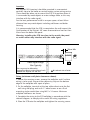
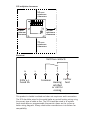
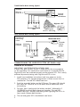
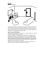
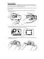
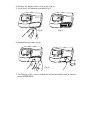
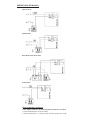
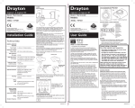
Digistat+1 & Digistat+1RF
Room Thermostat
Models:
RF710/22190/22192
Invensys Controls Europe
Technical Helpline: +44 (0) 845 130 7722
www.draytoncontrols.co.uk
)NSTALLATION 'UIDE
2& 02/$5#4 /.,9
).34!,,!4)/. /& 3#2 2& -ODELS ONLY
Digistat SCR
On
Receive / Alarm
Override
2
1
Learn
Mode
Wireless System
If you do not have the knowledge to install the SCR safely then you
must arrange for a competent electrician to install it for you. Wiring
must conform to the current IEE wiring regulations.
Prior to commencing the installation you must ensure the mains
supply is switched off.
)NSTALLATION )NSTRUCTIONS
2EAD ALL INSTALLATION AND COMMISSIONING INSTRUCTIONS BEFORE
PROCEEDING
$O NOT SWITCH ON UNTIL READY TO COMMISSION
The system wiring must be able to be fully disconnected from the
mains supply by a switch incorporated in the fixed wiring having a
contact separation of at least 3mm on both poles. Fused at 3A.
,OCATION
The Digistat SCR (receiver) should be mounted in a convenient
position, close to the boiler or central heating system wiring centre.
(Care should be taken not to mount the SCR in a position where it
is surrounded by metal objects or mains voltage cable, as this may
interfere with the radio signal).
For the best performance install in an open space, at least 30cm
distance from any metal objects including wall boxes and boiler
housing.
It is recommended that the SCR is mounted on the wall nearest the
final location of the Digistat +RF room thermostat and not less than
30cm from the boiler side panel.
7ARNING )NSTALLING THE 3#2 TOO CLOSE TO THE METAL SIDE PANEL
OR MAINS CABLES MAY INTERFERE WITH THE RADIO SIGNAL
30cm Min
BOILER
SCR
Radio Signal Range:
30m Typically
The range may be affected by
composition/density and number of walls
between the Digistat +RF and SCR
Preferred side of boiler
&IXING MINIMUM WALL PLATE CLEARANCES SHOWN
1. Loosen the securing screws, remove the wallplate, and if surface
wiring is to be used, snap out the cable entry strip on the bottom
edge of the wallplate with a pair of pliers.
2. Fix the wallplate, terminals at the top, either direct onto the flat
wall using wall plugs and no 6 x1” wood screws or on a flush
mounting single conduit box using M3.5 x 14 screws. Minimum
wallplate clearances are shown.
3. Complete the wiring to the SCR wallplate in accordance with the
relevant diagram, to comply with current IEE wiring regulations.
4. Place the SCR onto the wallplate and tighten the securing screws.
3#2 WALLPLATE CLEARANCES
50 mm
minimum
clearance
N L
1
2
3
4
40 mm
minimum
clearance
40 mm
minimum
clearance
70 mm
minimum
clearance
%LECTRICAL
Volt free contacts
N
230V a.c.
Fused 3A
L
1
Common
2
3
Call for
Heating heat
satisfied
or call for
cooling
This product is double insulated and does not require an earth connection.
The SCR should be wired to the combi boiler or central heating wiring using
the correct type of cable or flex. The SCR should be wired in to replace
hard wired room or programmable thermostats shown on the system or
boiler wiring diagrams. Always check other manufacturers instructions for
compatibility.
#OMBI BOILER BASIC WIRING LAYOUT
Switched
Internal
boiler
electronics
230V a.c. L fused 3A, N -
N
L
1
2
Digistat + RF
3
SCR
External
controls
connections
Radio signals
to SCR - no wiring
:ONE CONTROL BASIC WIRING LAYOUT
Switched live
from wiring
centre
Motorised valve
N
To boiler
and/or
pump
L
230V a.c.
fused 3A
N
L
1
SCR
2
3
Digistat + RF
Radio signals
to SCR - no wiring
#/--)33)/.).' 4(% j7)2%,%33 3934%-k 2& -ODELS ONLY
Standard for all models
IMPORTANT: MULTIZONE INSTALLATIONS ONLY
If more than one ‘wireless system’ is fitted within the same property.
ie. for controlling 2 or more zones (multi-zone) it is essential that the
Digistat RF units are matched correctly to the relevant SCR. This is easily
achieved by commissioning each Digistat and SCR in turn.
1. Install (see installation instructions) and turn power on to the
SCR (receiver). If a separate programmer is fitted, ensure that it is
switched on. The red LED should come on.
2. Push the ‘override’ button on the SCR once. The green LED should
also come on. Check to see if the boiler and/or motorised valve
are working.
3. To enter ‘learn’ mode push the button marked 1 followed by 2
(OVERRIDE) and hold both depressed together. The red LED
should flash for 2 seconds and then go out signifying the SCR is in
learn mode. Release both buttons.
4. The red and green LED’s should both now be on.
5
5. Take the Digistat RF and hold it within sight of the SCR (no closer
than one metre).
6. Remove the battery cover and fit the batteries.
7. The Digistat RF should now display the actual room temperature.
If the unit has been stored in a cold place, it may take time to warm
up.
8. As soon as the batteries are fitted, the red LED on the SCR should
flash for 7 seconds and then go out.
The green LED may be on or off depending on the room temperature
at the time of commissioning.
9. If the red LED remains on, remove the batteries on the Digistat RF,
check the battery positions are correct, and once the display has
faded, repeat steps 6 to 8.
10. Increase the ‘SET’ temperature on the Digistat RF by pressing the
+ button until a flame symbol appears, in the left hand segment of
the display.
11. The red LED on the SCR should flash for 7 seconds. This confirms
that the radio signal is being sent and received. After 7 seconds the
red LED should go out and the green one come on.
12. Check to confirm that the boiler and/or motorised valves are
working.
13. Decrease the ‘SET’ temperature on the Digistat RF by pressing the
- button until the flame symbol disappears.
14. The red LED on the SCR should flash for 7 seconds. After 7 seconds
both the red and green LEDs should go out. Check that the boiler
and/or motorised valve have powered down.
15. Place the Digistat RF in the chosen operating position, (see Digistat
RF location section) and repeat steps 10 to 14. Once you have
confirmed the system operates correctly, fit and secure the Digistat RF
to the wall (see installation instructions).
During normal operation the red LED on the SCR will flash for 7 seconds
each time a radio signal is received from the Digistat RF. This will occur
approximately every 5 minutes.
The green LED on the SCR denotes a call for heat (ON).
/NCE THE SYSTEM HAS BEEN SUCCESSFULLY COMMISSIONED BUTTONS AND ON THE 3#2 SHOULD NOT BE PRESSED SIMULTANEOUSLY UNLESS A
REPLACEMENT $IGISTAT 2& OR 3#2 IS ØTTED
,OCATION
Room Thermostat
1.5
m
Care should be taken to mount the thermostat in a position which is not
subject to direct sunlight or draughts. Preferably it should be mounted
on an inside wall about 1.5m (5ft) above the floor in a position where it
can respond to room temperature but away from the direct influence of
radiators or other appliances giving off heat.
3IGNAL 3TRENGTH 2& -ODELS
Before fixing the Digistat+RF to the wall it is recommended to first check
the signal strength from that location.
To do this, remove the batteries, press and hold the ‘+’ button whilst
refitting the batteries, the display will show ‘rF’ which indicates that the
Digistat+RF is continuously sending an OFF signal to the SCR (receiver).
Leave the Digistat+RF in position and return to view the SCR. If the red
LED is continuously flashing, this indicates a good signal. If the red LED is
not flashing, this indicates a poor signal and you need to reposition the
Digistat+RF until the red LED is flashing.
When the signal strength has been confirmed remove the batteries to
cancel the test and follow the installation instructions.
"EFORE )NSTALLATION
If you do not have the knowledge to install the thermostat safely then
you must arrange for a competent electrician to install it for you. Wiring
must conform to the current IEE regulations.
Prior to commencing the installation you must ensure the mains supply is
switched off.
1. Remove the front cover using a flat screwdriver and separate from
back plate (Fig 1).
Drayton
(Fig 1)
2. Fix the back plate directly onto the wall using suitable wall plugs and
screws or mount over existing wall box (Fig 2).
(Fig 2)
3. Replace the front cover by locating in position and pushing fully onto
the back cover (Fig 3).
Drayt
on
(Fig 3)
4. Remove the battery cover using a coin (Fig 4).
5. Install the 2 AA batteries provided (Fig 5).
Drayton
Drayton
(Fig 4)
(Fig 5)
6. Replace battery cover (fig 6).
Drayton
Drayton
(Fig 6)
7. The Digistat +1RF is now installed and will automatically start to control the
room temperature.
7)2).' .OT 2& -ODELS
%LECTRIC (EAT
Combi Boiler
"ASIC "OILER WITH :ONE 6ALVE
"ASIC "OILER
&!5,4 $)!'./3)3 !LL -ODELS
)F THE DISPLAY SHOWS % THE FOLLOWING FAULTS COULD HAVE OCCURRED
1. Internal temperature sensor has failed.
2. Ambient temperature is outside product operating temperature range.
Technical Data
$)')34!4 $)')34!42&
2//- 5.)4
0OWER 3UPPLY
2 x AA Size, 1.5V alkaline batteries
3WITCH 4YPE 2ATING
2ELAY VERSION
-IN RECOMMENDED
CURRENT
SPDT 16(2)A 230V a.c. Volt free
10mA@24V a.c. (inductive)
2ADIO FREQUENCY
2& VERSION
Radio Signal Range:
2& 6ERSION
433 MHz
30m typically. The range may be affected by
the composition / density and number of
walls between the Digistat RF and SCR.
Temperature Range:
#ONTROL !CCURACY
5 to 30ºC
+ 0.5K @ 20ºC
!MBIENT 4EMPERATURE Operating 0ºC to 40ºC /
Storage –20ºC to 55ºC
Mounting:
Suitable for surface or conduit box
mounting
Wiring:
Relay:
Designed for fixed wiring only, to comply
with current IEE wiring regulations (BS7671).
2&
"ALL 0RESSURE 4EST
0OLLUTION $EGREE
No wiring required
75ºC
2
$)')34!4 3#2
0OWER 3UPPLY
3WITCH 4YPE 2ATING
230V a.c.
SPDT (voltage free) 2(1)A 230V a.c. or
24V a.c./d.c.
Wiring:
Designed for fixed wiring only, to comply
with current IEE wiring regulations (BS7671).
2ECEPTION &REQUENCY
2ELEVANT %#
DIRECTIVES
433 MHz
2006/95/EC Low Voltage Directive
2004/108/EC Electromagnetic
Compatibility Directive
1999/5/EC R&TTE Directive
2006/66/EC Battery Directive
!PPLIED 3TANDARDS
EN 60730-1, EN 60730-2-9
ETSI EN 300 220-3, ETSI EN 301 489-3
C
Digistat+1 & Digistat+1RF
Room Thermostat
Models:
RF710/22190/22192
Invensys Controls Europe
Technical Helpline: +44 (0) 845 130 7722
www.draytoncontrols.co.uk
User Guide
What is a room thermostat?
... An explanation for householders
A room thermostat simply switches the heating system on
and off as necessary. It works by sensing the air temperature,
switching on the heating when the air temperature falls below
the thermostat setting, and switching it off once this set
temperature has been reached.
Turning a room thermostat to a higher setting will not make
the room heat up any faster. How quickly the room heats up
depends on the design of the heating system, for example, the
size of boiler and radiators.
Neither does the setting affect how quickly the room cools
down. Turning a room thermostat to a lower setting will result
in the room being controlled at a lower temperature, and saves
energy.
The heating system will not work if a time switch or programmer
has switched it off.
The way to set and use your room thermostat is to find the
lowest temperature setting that you are comfortable with,
and then leave it alone to do its job. The best way to do this
is to set the room thermostat to a low temperature – say 18ºC
– and then turn it up by one degree each day until you are
comfortable with the temperature. You won’t have to adjust the
thermostat further. Any adjustment above this setting will waste
energy and cost you more money.
If your heating system is a boiler with radiators, there will
usually be only one room thermostat to control the whole
house. But you can have different temperatures in individual
rooms by installing thermostatic radiator valves (TRVs) on
individual radiators. If you don’t have TRVs, you should choose
a temperature that is reasonable for the whole house. If you do
have TRVs, you can choose a slightly higher setting to make sure
that even the coldest room is comfortable, then prevent any
overheating in other rooms by adjusting the TRVs.
Room thermostats need a free flow of air to sense the
temperature, so they must not be covered by curtains or
blocked by furniture. Nearby electric fires, televisions, wall or
table lamps may prevent the thermostat from working properly.