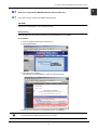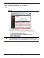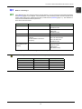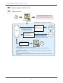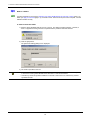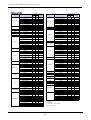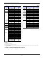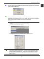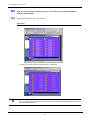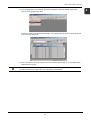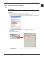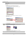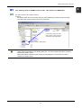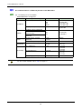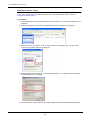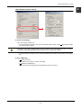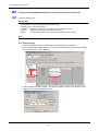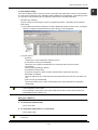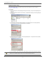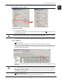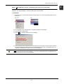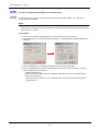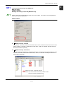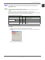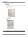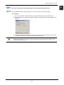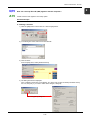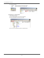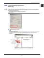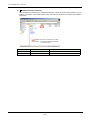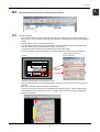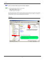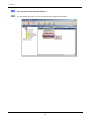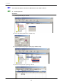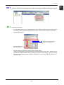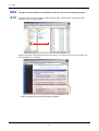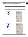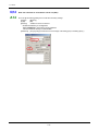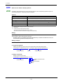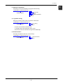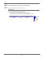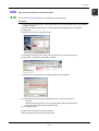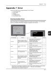
1
Q&A
Hakko Electronics Co., Ltd.
Contents
1
Common to SOFT MONITOUCH TELLUS and V-Server
Q1 How can I acquire SOFT MONITOUCH TELLUS and V-Server?.............................................................. 1-1
Q2 Can I update SOFT MONITOUCH TELLUS and V-Server? ...................................................................... 1-2
Q3 What is "licensing"?.................................................................................................................................... 1-3
Q4 How can I apply for software license?........................................................................................................ 1-4
Q5 What is a user ID?...................................................................................................................................... 1-5
Q6 What is a PCID?......................................................................................................................................... 1-6
Q7 What is a password?.................................................................................................................................. 1-7
Q8 What is the operating environment for SOFT MONITOUCH TELLUS and V-Server?............................... 1-8
Q9 Compatible list (MONITOUCH, PLC, etc.) for SOFT MINOTOUCH TELLUS and V-Server ..................... 1-9
2
SOFT MONITOUCH
TELLUS
Q1 The error message “Error Code Received. Received Code: [5]” appears
(on the simulator in the emulation or HMI mode) ....................................................................................... 2-1
Q2 How do I register memory addresses of the screen data in the simulator
(emulation enabled) automatically? ........................................................................................................... 2-2
Q3 The remote mode has been used 100 times.
Can I use the remote mode again by reinstalling TELLUS? ...................................................................... 2-4
Q4 Can I switch between Chinese and English? ............................................................................................. 2-5
Q5 I use memory cards or SRAMs on the V series. How about in the HMI mode?........................................ 2-7
Q6 Are communications via Ethernet possible in the HMI mode?................................................................... 2-8
Q7 Connection with Yokogawa FA-M3 via Ethernet cannot be established.................................................... 2-9
Q8 Connection with MITSUBISHI QnH(Q) series via Ethernet cannot be established.................................. 2-12
Q9 Displayed characters are garbled or do not fit in the designated spaces................................................. 2-16
Q10 Are macro commands executable in the remote mode?.......................................................................... 2-18
Q11 I cannot do the following in the HMI mode:
WAV file replay
JPEG file display
Reading and writing a recipe file [RECxxxx.csv]...................................................................................... 2-19
Q12 I click a switch on the screen in the remote mode,
but the data is not written to the MONITOUCH or PLC............................................................................ 2-21
Q13 How can I synchronize the remote-mode screen with the monitored device? ......................................... 2-23
Q14 Can I use the memory manager function in the remote mode? ............................................................... 2-24
Q15 How can I start up TELLUS (HMI) together with the computer? .............................................................. 2-25
Q16 I cannot do the following in the remote mode:
WAV file replay
JPEG file display ...................................................................................................................................... 2-27
Q17 Can I use the recipe mode function in the remote mode? ....................................................................... 2-29
Q18 The screen of the monitored device does not shift even
when I shift the screen in the remote mode. ............................................................................................ 2-30
3
V-Server
Q1 How many monitored devices can be registered? ..................................................................................... 3-1
Q2 Are there any restrictions on monitoring multiple devices by V-Server?.................................................... 3-2
Q3 The monitored device comes to a STOP state on V-Server. ..................................................................... 3-3
Q4 How can I transfer V-Server projects to another computer? ...................................................................... 3-4
Q5 Can I transfer recipe data created on Excel to the PLC?........................................................................... 3-5
Q6 Can I transfer screen data from V-Server? ................................................................................................ 3-6
Q7 Can I monitor a MONITOUCH from a remote location?............................................................................. 3-7
Q8 Can I show the values in the PLC or Monitouch in real time on Excel?..................................................... 3-8
Q9 Is the number of tags (page 3-8) to be registered limited? ........................................................................ 3-9
Q10 Is the number of logs to be registered limited? ........................................................................................ 3-10
Q11 I want to use alarm monitoring function, but the option [Alarm Monitor Setting] is inactive. .................... 3-11
Q12 Though a monitored device is updated from V-Server, the version number goes down. ........................ 3-12
Q13 How can I save one-day (24-hour continuous) sampling data in a file?................................................... 3-13
Q14 How can I execute an event when a bit is set (ON)? ............................................................................... 3-14
Q15 Is the arithmetic function included as a condition for an event?............................................................... 3-15
Q16 What are the V-Server startup options?................................................................................................... 3-16
Q17 Can I set multiple V-Server startup options* at the same time?............................................................... 3-18
Q18 How can I start V-Server at the desired time? ......................................................................................... 3-19
Q19 Can I write from multiple logs to the same Excel file?.............................................................................. 3-20
1
Common to
SOFT MONITOUCH TELLUS
and V-Server
1 Common to SOFT MONITOUCH TELLUS and V-Server
Q1
How can I acquire SOFT MONITOUCH TELLUS and V-Server?
A1
There are two ways: using the CD-ROM and downloading.
CD-ROM
Contact your local distributor if you need the CD-ROM.
Downloading
SOFT MONITOUCH TELLUS and V-Server can be downloaded from our website.
♦ Procedure
1) Visit our website at http://www.monitouch.com.
2) Click [DOWNLOAD].
3) Click [TELLUS & V-Server].
The software can be downloaded. Follow the instructions given.
4) After the desired software is downloaded, perform the installation.
From our website, it is also possible to download the update modules. Use this service when updating
your installed SOFT MONITOUCH TELLUS or V-Server.
1-1
1
1 Common to SOFT MONITOUCH TELLUS and V-Server
Q2
Can I update SOFT MONITOUCH TELLUS and V-Server?
A2
Yes, the update modules can be downloaded from our website.
Procedure
1) Visit our website at http://www.monitouch.com and open the Download page.
2) Download the update modules.
3) On completion of downloading, double-click the compressed file [_tellusxxxx.exe] or
[_vserverxxxx.exe]. It is decompressed and a [tellus] or [vserver] folder will be created.
4) Open the folder and copy all the files in it.
5) Paste these files in the SOFT MOINTOUCH TELLUS or V-Server folder* that is already installed on
your computer. The existing files will be overwritten.
* TELLUS and V-Server folders are installed in the following locations as default.
TELLUS:
C:\Program Files\Tellus
V-Server: C:\Program Files\V-Server
Another method for updating the existing software is to install the software in the latest version. In this
case, re-entering the password (page 1-7) is required to remove the restrictions on the software.
Therefore, keep the password you received when you applied for the software license (page 1-4) in a
secure place.
1-2
1 Common to SOFT MONITOUCH TELLUS and V-Server
Q3
A3
1
What is "licensing"?
SOFT MONITOUCH TELLUS and V-Server are free software. You can use them as restricted trial software
until licensing (page 1-4) is complete. Once the decision of the necessary function and the computer to be
used is made, apply for the software license and you will receive a password (page 1-7). The restriction is
removed from the software with the password.
There are 5 kinds of licenses:
License
Software
Available Mode
TELLUS-HMI
SOFT MONITOUCH TELLUS
HMI mode
Emulation mode
TELLUS-Remote
SOFT MONITOUCH TELLUS
Remote mode*
HMI mode
Emulation mode
V-Server
V-Server
V-Server
TELLUS & V-Server
SOFT MONITOUCH TELLUS
V-Server
(To be installed on the same
computer)
V-Server
TELLUS remote mode*
TELLUS HMI mode
Emulation mode
TELLUS-OP-L
(PLC ladder monitor
function)
SOFT MONITOUCH TELLUS
Ladder monitor
(Remote mode)
(HMI mode)
(Emulation mode)
* It is required that V-Server be running on a networked computer.
The following restrictions are imposed until licensing is complete:
Mode
Emulation mode
Running Time
1 hour
Startup Count
Not limited
HMI mode
1 hour
Not limited
Remote mode
1 hour
100 times
V-Server
1 hour
Not limited
Ladder monitor
1 hour
Not limited
1-3
1 Common to SOFT MONITOUCH TELLUS and V-Server
Q4
How can I apply for software license?
A4
Follow the steps below:
V-Server
When one hour has elapsed after startup, a warning
message is displayed and the application is terminated.
TELLUS
Install
Trial period
TELLUS-Remote is allowed to be used 100 times.
Procedure for
licensing
(Example) Applying for one license of TELLUS-Remote
Application form
In the application form, include the
desired number of licenses and the
PCIDs of the individual computers
on which these licenses will be used.
License *1
TELLUS-Remote: 1 license
Local
distributor
PCID*2: 1111111111 (example)
User
User ID *3
ID: 00000000 (example)
HAKKO
PCID: 1111111111 (example)
Password: 9999999999 (example)
A user ID (only at the time of the initial
application) and the passwords for the
individual PCIDs will be e-mailed or faxed.
The relevant documents will be sent by post.
TELLUS
Remote
At application startup, enter
the password corresponding
to the PCID.
Licensing
completed
Restriction
removed
*1) Licenses: 5 kinds
Apply for necessary licenses according to your desired functions.
If a wrong application is made and then a password is granted, you need to apply again for the correct license.
*2) PCID: ID specific to a computer
Until the procedure for licensing is complete, the ID is displayed in the [Password Setting] dialog box at the application
startup.
*3) User ID: One ID to be granted to one user
The user ID is required when you apply for additional licenses or acquire passwords from our website. Keep the user ID
in a secure place.
1-4
1 Common to SOFT MONITOUCH TELLUS and V-Server
Q5
A5
1
What is a user ID?
When you apply for a license for the first time (page 1-4), we will issue a user ID. One user ID is granted per
user.
Do not lose the user ID since it is required when you apply for additional licenses afterward.
1-5
1 Common to SOFT MONITOUCH TELLUS and V-Server
Q6
A6
What is a PCID?
A PCID is required for removing the restriction from SOFT MONITOUCH TELLUS and V-Server (page 1-3).
When you apply for a license (page 1-4), the PCID is used. The PCID is unique to each computer. Use the
individual PCIDs correctly.
♦ How to check the PCID:
1) Start the SOFT MONITOUCH TELLUS or V-Server. The dialog box below appears. However, it
does not appear if licensing has been completed and the password has been entered.
2) Click the [Yes] button.
The [Password Setting] dialog box is displayed.
3) The PCID is specified in the box.
• Every PCID is computer-specific. When you apply for a license, check the PCID on the computer
to be used for running SOFT MONITOUCH TELLUS or V-Server beforehand.
• A PCID may consist of symbols in addition to numerals. Take care not to overlook any of these
symbols/numerals.
1-6
1 Common to SOFT MONITOUCH TELLUS and V-Server
Q7
A7
1
What is a password?
The password is required for removing the restriction from SOFT MONITOUCH TELLUS and V-Server
(page 1-3). It will be acquired by the application for a license (page 1-4). Every password is specific to each
computer. A password and a PCID (page 1-6) are used as a pair on their corresponding computer.
Therefore, a password for one computer is not valid on another computer. This point should be noted when
you specify a PCID at the time of applying for a license.
1-7
1 Common to SOFT MONITOUCH TELLUS and V-Server
Q8
What is the operating environment for SOFT MONITOUCH TELLUS and V-Server?
A8
♦ SOFT MONITOUCH TELLUS
Computer
Pentium II 450 MHz or equivalent or more recommended
OS
Windows 98/Me/NT version 4.0/2000/XP (XP recommended)
Memory
32 MB or more
Hard disk
30 MB or more
♦ V-Server
Computer
Pentium II 450 MHz or equivalent or more recommended
OS
Windows 98/Me/NT version 4.0/2000/XP (XP recommended)
Memory
32 MB or more
Hard disk
50 MB or more
1-8
1 Common to SOFT MONITOUCH TELLUS and V-Server
Q9
Compatible list (MONITOUCH, PLC, etc.) for SOFT MONITOUCH TELLUS and V-Server
A9
♦ SOFT MONITOUCH TELLUS
Screen Data File
Extension
MONITOUCH
Remarks
Emulation mode
−
.V6/.V7
Some functions are not
supported.*1
HMI mode
−
.V6/.V7
Usable PLC models are
limited.
Some functions are not
supported.*1
.V6/.V7
V606/V606e/V609E/V608CH
are not available because
communicating via Ethernet is
not enabled.
Usable PLC models are
limited.
Remote mode
V7i series
V7 series + CU-03
V706 + DU-01
V612 + CU-03
V610 + CU-03
V608 + CU-03
V606i + CU-03
*1 For more information, refer to the SOFT MONITOUCH TELLUS and V-Server manuals.
♦ V-Server
Screen Data File
Extension
MONITOUCH
V-Server
V7i series
V7 series + CU-03
V706 + DU-01
V612 + CU-03
V610 + CU-03
V608 + CU-03
V606i + CU-03
1-9
.V6/.V7
Remarks
V606/V606e/V609E/V608CH
are not available because
communicating via Ethernet is
not enabled.
1
1 Common to SOFT MONITOUCH TELLUS and V-Server
2004/2/10
PLC Models for TELLUS
TELLUS HMI
Maker
Allen-Bradley
Automationdirect
Baldor
DELTA
FANUC
FATEK
AUTOMATION
FESTO
PLC
䋱䋺䋱
䋱䋺䌮
PLC-5
PLC-5 (Ethernet)
SLC500
SLC500 (Ethernet)
Micro Logix 1000
Control Logix
Control Logix (Ethernet)
Direct LOGIC
Direct LOGIC (K-Sequence)
Direct LOGIC (Ethernet)
Mint
DVP series
Power Mate
䂾
䂾
䂾
䂾
䂾
䂾
䂾
䂾
䂦
䂦
䂦
䂦
䂦
䂦
䂾
䂦
䂾
䂦
䂦
䂾
䂦
㬍
䂦
䂦
䂦
㬍
䂾
䂾
䂾
䂾
䂾
䂾 *4
䂾 *4
䂾
䂾
䂾
䂾
䂦
䂾
FACON FB series
䂦
䂦
䂦
FEC
MICREX-F series
䂦
䂾
䂦
䂾
䂾
䂾
×
×
䂔
䂾
䂾
䂾
䂦
䂦
䂾
䂦
䂦
䂦
䂦
䂦
䂦
䂾
䂾
䂦
×
×
HIDIC-S10/2α
×
䂾
䂾
䂾
䂾
䂾
䂦
㬍
䂦
×
䂔
䂾 *8
䂾
䂾
䂾
䂾
HIDIC-S10/ABS
䂦
×
䂾
HIDIC-S10 (OPCN-1)
×
×
×
MICREX-F (T link)
FUJI
GE䇭Fanuc
HITACHI
IDEC
SPB (N mode)
& FLEX-PC series
SPB (N mode) & FLEX-PC CPU
FLEX-PC COM (T)
FLEX-PC (T)
FLEX-PC CPU (T)
FLEX-PC CPU (OPCN-1)
MICREX-SX (all)
90 series
90 series (SNP-X)
HIDIC-H
HIDIC-S10/2α, S10mini
(Ethernet)
HIDIC-S10V
HIDIC-S10V (Ethernet)
MICRO3
MICRO Smart
KZ series link
KZ-A500䇭CPU
KZ/KV series CPU
TELLUS HMI
TELLUSremote *9
& V-Server
䂾
䂾
䂾
䂾 *2
䂾
䂾
䂾
䂾
䂾
䂦
×
䂾
䂦
䂦
䂦
㬍
㬍
䂾 *3,4
䂾 *3,4
䂾
䂾
䂾
䂾
䂾
Maker
MITSUBISHI
MODICON
MOELLER
OMRON
SAIA
SAMSUNG
SHARP
SHINKO
SIEMENS
KEYENCE
KZ24/300䇭CPU
䂦
㬍
䂾
䂦
䂾
䂦
䂾
䂾
䂦
㬍
㬍
䂦
䂦
䂦
×
䂾
䂾
䂾
䂾
䂾
䂾
TAIAN
Telemecanique
KOYO
KV10/24䇭CPU
KV-700 CPU
KV-700 (Ethernet)
SU/SG
SR-T
SR-T (K protocol䋩
SU/SG 䋨K-Sequence䋩
䂦
×
䂾
TOSHIBA
MACHINE
MASTER-K10/60/200
MASTER-K500/1000
MASTER-KxxxS
MASTER-KxxxS CNET
MASTER-K series 䋨Ethernet䋩
GLOFA䇭CNET
GLOFA GM series CPU
GLOFA GM series CPU
(Ethernet)
MEWNET
FP series (Ethernet TCP/IP)
FP series (Ethernet UDP/IP)
A series link
A series CPU
A series (OPCN-1)
A series (CC-LINK)
Q䌮A series link
Q䌮A series CPU
QnA series (CC-LINK)
QnA series (Ethernet)
QnH(Q) series link
QnH(A) series CPU
QnH(Q) series CPU
Q00J/00/01 CPU
䂦
䂦
䂦
䂦
䂦
䂦
䂦
㬍
䂦
㬍
䂦
䂦
䂦
㬍
䂾
䂾
䂾
䂾
䂾
䂾
䂾
䂦
䂦
䂾
䂦
䂦
䂦
䂾
䂾
×
×
䂦
㬍
䂦
䂾
×
×
×
䂾
䂾
×
䂾
×
×
䂾
䂾
䂾
䂾
䂾
䂾
䂦
×
×
×
䂾
䂾
䂾
䂾
䂾
䂔
䂔
䂾
䂾
䂔
䂾
䂾
䂾
䂾
䂾
LG
MATSUSHITA
MITSUBISHI
TOSHIBA
TOYOPUC
VIGOR
YAMATAKE
YASKAWA
YOKOGAWA
PLC
䋱䋺䌮
PS4
SYSMAC C
SYSMAC C (OPCN-1)
SYSMAC CV
䂾
䂦
䂔
䂾
䂾
䂾
䂾
䂾
䂔
䂾
䂾
䂾
䂾
䂔 *1
䂾
SYSMAC CS1/CJ1
䂾
䂾
䂾
SYSMAC CS1/CJ1 DNA
SYSMAC CS1/CJ1(Ethernet)
SYSMAC CS1/CJ1
(Ethernet Auto)
SYSMAC CS1/CJ1 DNA
(Ethernet)
PCD
SPC series
N_plus
SECNET
JW series
JW100/70H COM port
JW20 COM port
JW (FL-N䌥䌴䋩
JW series (Ethernet)
JW300 series
JW311/312/321/322 series
(Ethernet)
JW331/332/341/342/352/362
series (Ethernet)
䂦
䂾
䂦
䂾
䂾 *1
䂾
䂾
䂾
䂾
䂾
䂾
䂾
䂦
䂦
䂦
䂦
䂾
䂾
䂾
×
䂦
䂦
䂦
䂦
䂦
䂦
䂾
×
䂦
䂾
䂾
䂾
䂾
䂾
䂾
×
䂾
䂦
䂾
䂦
䂾
䂦
䂦
䂦
䂦
䂦
䂦
䂦
QnH(Q) series (CC-LINK)
QnH(Q) series (Ethernet)
FX series CPU
FX2N series CPU
FX1S series CPU
FX series link (A protocol)
Net10
A link + Net10
Modbus RTU
×
×
䂾
䂾
䂾
䂾
䂾
×
×
䂾
×
×
×
䂦
䂦
䂾
×
䂾
×
䂾
䂦
䂦
䂾
×
SELMART
䂦
䂦
䂾
S5
S5 PG port
S7
S7-200 PPI
S7-300/400MPI
S7-300MPI (HMI ADP)
S7-300MPI (PC ADP)
S7-300MPI
(Helmholz SSW7 ADP)
S7 PROFIBUS-DP
TI500/505
TP02
TSX Micro
T series
EX series
䂾
䂾
䂾
䂦
䂦
䂾
䂾
㬍
䂦
㬍
䂦
䂦
㬍
㬍
䂾
䂾
䂾
䂦
䂦
䂾
䂾
䂾
㬍
䂾 *7
㬍
䂦
䂦
䂾
䂦
䂦
㬍
㬍
䂦
㬍
䂦
䂦
䂦 *7
䂾
䂾
䂾
䂾
䂾
TC200
䂦
䂦
䂦
TOYOPUC
TOYOPUC (Ethernet)
M series
MX series
Memobus
CP9200SH/MP900
FA500
䂦
䂦
䂦
䂦
䂦
䂦
䂾
䂦
䂦
䂦
䂦
䂦
䂦
䂦
*7
*7
*7
*7
*7
*7
*7
FA-M3
䂾
䂾
䂾
䂾
䂦
䂾
䂾 *6
䂾
䂾 *5
*5
䂾
FA-M3R
FA-M3/FA-M3R (Ethernet)
FA-M3R(FL-N䌥䌴䋩
MODBUS RTU (Free Format)
MODBUS TCP/IP (Ethernet)
Universal serial
Universal FL-Net
Universal PROFIBUS-DP
W/O PLC connection
Simulator
䂾
䂾
×
䂾
䂾
×
䂾 *5
䂾 *5
×
䂦
䂦
䂾
㬍
䂦
䂾
䂾
䂦
䂦
䂾
㬍
䂦
㬍
㬍
䂾
䂾
䂾
㬍
䂔
䂾
㬍
䂾: Available
㬍: Not available
䂦: Consult with your local distributor.
䂔: Available with V7i only
1-10
䋱䋺䋱
TELLUSremote *9
& V-Server
1 Common to SOFT MONITOUCH TELLUS and V-Server
Note: Connection in the HMI mode does not support multi-link and multi-link 2.
*1: Only transfer mode 1 is allowed.
*2: Only RS422 is allowed.
*3: In a case where [Trigger: Memory] and [Type: Word] are specified in the V-Server [Event Setting] dialog box, processing is performed in units of one word, even with
䇭䇭a double-word device.
*4: In a case where [Trigger: Memory ] and [Type: Bit] are specified in the V-Server [Event Setting] dialog box, high-order bits (bit 16 through bit 31) of a double-word device
䇭䇭are not usable.
*5: Macro command [PLC_ULR] is not supported.
*6: Only transfer mode type 2 is allowed.
*7: In a case where [Trigger: Memory] and [Type: Bit] are specified in the V-Server [Event Setting] dialog box, PLC memory is not usable.
*8: T-link, OPCN-1, and SX bus are available with V7i only.
*9: If "䂾" is shown and also if "TELLUS HMI 1:1" is marked with "䂦" or "X", the message "Remote mode is not supported." will appear. Ignore the message and go ahead
䇭䇭with the operation.
1-11
1
1 Common to SOFT MONITOUCH TELLUS and V-Server
Temperature Controller & Inverter Models for TELLUS
Maker
A&D
CHINO
EUROTHERM
FUJI
HITACHI
IAI
LG
MITSUBISHI
Modbus Free
M-SYSTEM
NIKKI DENSO
OHKURA
OMRON
RKC
Temperature controller
TELLUS HMI
AD4402 䋨MODBUS RTU)
AD4404 䋨MODBUS RTU)
DZ1000 (MODBUS RTU)
DZ2000 (MODBUS RTU)
KP1000
LT400 Series (MODBUS RTU)
2400 series (MODBUS RTU)
PYX (MODBUS RTU)
PYH
PXR (MODBUS RTU)
F-MPC04P
FVR-E11S
FVR-C11S
FRENIC5000G11S/P11S
FRENIC5000VG7S
FRENIC-Mini 䋨MODBUS RTU䋩
HFR-C9K
PPMC 䋨MODBUS RTU䋩
FALDIC-α Series
PH Series
SJ300 Series
L300P Series
Super SEL Controller
X-SEL Controller
iS5
iG5
FR-*500
MR-J2S-*A
MR-J2S-*CL
R1M Series 䋨MODBUS RTU)
R5 Series 䋨MODBUS RTU)
SQB-6432B
EC5500S
EC5800
EC5600S
EC5900A
E5CK
E5ZE
E5ZD
E5EK
E5EK-T
E5AK
E5AK-T
E5CK-T
E5AN/E5EN/E5CN/E5GN
E5ZN
E5AR/E5ER
V600/V620
SR-Mini (MODBUS RTU)
CB100/CB400/CB500/
CB700/CB900(MODBUS RTU)
SR-Mini (Standard Protocol)
REX-F400/F700/F900
(Standard Protocol)
REX-F9000
(Standard Protocol)
SRV (MODBUS RTU)
䂾
䂾
䂦
䂦
䂦
䂦
䂾
䂦
䂦
䂦
䂦
䂦
䂦
䂦
䂦
䂦
䂦
䂦
䂦
䂦
䂦
䂦
䂦
䂦
䂦
䂦
䂦
䂦
䂦
䂦
䂾
䂾
䂦
䂦
䂦
䂦
䂦
䂾
䂾
䂾
䂾
䂾
䂾
䂾
䂾
䂾
䂾
䂾
䂦
䂾
TELLUS
remote
䋧V-Server
䂾
䂾
䂾
䂾
䂦
䂾
䂾
䂾
䂾
䂾
䂾
䂾
䂾
䂾
䂾
䂾
䂾
䂦
䂦
䂾
䂾
䂾
䂾
䂾
䂾
䂾
䂾
䂦
䂦
䂾
䂾
䂾
䂾
䂾
䂾
䂾
䂾
䂾
䂾
䂾
䂾
䂾
䂾
䂾
䂾
䂾
䂾
䂾
䂾
䂾
䂾
䂾
䂦
䂾
䂦
䂾
䂦
䂾
䂾
䂾
Maker
Temperature controller
TELLUS HMI
SAMSUNG
SANMEI
San Rex
MOSCON-E7
Cuty Axis
DC AUTO (HKD type)
C Series
FC Series
GC Series
DCL-33A
JC䌸-300 Series
VF-S7
VF-S9
VF-A7
F340A
F371
SDC10
SDC20
SDC21
SDC30/31
SDC40A
DMC10
SDC40G
DMC50
VS mini V7 Series
UT100
UT750
UT550
UT520
UT350
UT320
UP350
UP550
UP750
UM330
UM350
UT2400/2800
䂦
䂦
䂦
䂦
䂦
䂦
䂦
䂦
䂦
䂦
䂦
䂦
䂦
䂾
䂾
䂾
䂾
䂾
䂾
䂾
䂾
䂦
䂾
䂾
䂾
䂾
䂾
䂾
䂾
䂾
䂾
䂾
䂾
䂾
SHINKO
TECHNOS
TOSHIBA
UNIPULSE
YAMATAKE
YASKAWA
Yokogawa M&C
2004/2/10
TELLUS
remote
䋧V-Server
䂦
䂦
䂾
䂾
䂾
䂾
䂾
䂾
䂾
䂾
䂦
䂾
䂾
䂾
䂾
䂾
䂾
䂾
䂾
䂾
䂾
䂾
䂾
䂾
䂾
䂾
䂾
䂾
䂾
䂾
䂾
䂾
䂾
䂾
䂾: Available
㬍: Not available
䂦: Consult with your local distributor.
Note1: Macro TEMP_CTL is not available on remote mode.
Note2: In a case where [Trigger: Memory ] and [Type: Bit] are specified in the V-Server [Event Setting] dialog box, high-order bits (bit 16 through bit 31) of a double-word
䇭 device are not usable.
* For information on PLC2Way models supporting TELLUS, consult your local distributor.
1-12
2
SOFT MONITOUCH
TELLUS
♦Emulation mode
♦HMI mode
♦Remote mode
2 SOFT MONITOUCH TELLUS
Q1
The error message “Error Code Received. Received Code: [5]” appears (on the simulator
in the emulation or HMI mode)
A1
Error code 5 is displayed in case of access to an address that does not exist.
The emulation mode substitutes the simulator for the PLC. The simulator is provided with the [Memory
Setting] dialog box in which the range of memory can be specified. When you set memory in the dialog box,
be sure that the set memory is available in the PLC to be connected afterward.
Procedure
1) On the simulator software, select [PLC Type] from the [File] menu. Check to see that the PLC type is
correct.
2) From the above-mentioned [File] menu, select [Memory Setting].
The [Memory Setting] dialog box is displayed.
3) Enter the range of memory that is available in the PLC. Click the [OK] button.
Even if the memory addresses allocated to the screen data are not available in the PLC, it is possible
for the simulator to display the emulation screen. In this case, the memory addresses are within the
range set in the [Memory Setting] dialog box. However, when connection with the PLC has been
established, the MONITOUCH will show the error message “Error Code Received. Received Code:
[xx].” Therefore, it is recommended that the dialog box be set according to the range of memory
available on the PLC.
2-1
2
2 SOFT MONITOUCH TELLUS
Q2
How do I register memory addresses of the screen data in the simulator (emulation
enabled) automatically?
A2
Start both V-SFT and TELLUS at the same time.
Procedure
1) Start V-SFT and open the screen data.
2) Start TELLUS (the simulator in the emulation or HMI mode).
From the V-SFT [File] menu, select [Start Emulator]. The emulation-mode TELLUS starts.
Also, by clicking [Apply Emulate data], changes made to the screen data are reflected throughout the
TELLUS emulation screens.
2-2
2 SOFT MONITOUCH TELLUS
3) From the [File] menu of the simulator (emulation enabled) that has been started together with
TELLUS, select [Apply V-SFT data.]
A sheet is created on the simulator automatically. Any changes made to simulator values will also be
made to the TELLUS screen.
4) If the V-SFT screen has been changed, save the screen and perform step 3). The changes will be
reflected in the simulator.
When you are running TELLUS only (without starting V-SFT), memory registration should be made
manually. Proceed to file creation from the option [New] of the simulator.
2-3
2
2 SOFT MONITOUCH TELLUS
Q3
The remote mode has been used 100 times. Can I use the remote mode again by
reinstalling TELLUS?
A3
Unfortunately, no. TELLUS in remote mode can be used 100 times as a trial period (page 1-3).
If you want to use TELLUS in remote mode again, please apply for the license (page 1-4) and get a
password (page 1-7).
2-4
2 SOFT MONITOUCH TELLUS
Q4
Can I switch between Chinese and English?
A4
Yes. But the method differs, depending on the OS in use.
On Windows XP
The procedure below is required to make the Chinese display possible on the English OS.
♦ Procedure
1) From the [Start] menu, select [Settings] and then [Control Panel].
2) Double-click [Regional and Language Options]. The dialog box is displayed.
3) Under [Code page conversion tables] in the [Advanced] tab window, choose the Chinese language.
4) Click the [OK] button. Chinese (simplified) is now displayable on the English OS.
5) Start TELLUS.
6) Open the [Option] dialog box.
7) Make a setting under [Font]. According to the [Font Setting] set for the screen data, choose the font
for each language.
2-5
2
2 SOFT MONITOUCH TELLUS
On Windows 2000
The procedure below is required to make the Chinese display possible on the English OS.
♦ Procedure
1) From the [Start] menu, select [Settings] and then [Control Panel].
2) Double-click [Regional Options]. The dialog box is displayed.
3) Under [Language settings for the system], choose the Chinese language.
4) Click the [OK] button. Chinese (simplified) is now displayable on the English OS.
5) Start TELLUS.
6) Open the [Option] dialog box.
7) Make a setting under [Font]. According to the [Font Setting] set for the screen data, choose the font
for each language.
Changing the font settings after TELLUS startup
1. From the [File] menu or using the RUN/STOP icon, bring TELLUS to a stop.
[File] menu
Icon
2. From the [File] menu, select [Option]. The [Option] dialog box is displayed.
3. Under [Font], choose the font for each language.
2-6
2 SOFT MONITOUCH TELLUS
Q5
A5
I use memory cards or SRAMs on the V series. How about in the HMI mode?
The data is saved in the computer memory.
Locations:
• The SMPLE folder saves the sampling data (only when [SRAM/CF] is selected for [Store Target]).
• The CARD folder saves the data in the memory card mode.
In the location where the screen
data is saved, a folder under the
name of the screen data exists.
Data will be saved in these folders.
Sampling data will be saved in the SAMPLE folder, provided that [SRAM/CF CARD] is selected for
[Store Target] in the [Buffering Area Setting] dialog box. The save operation starts when the state is
switched from RUN to STOP.
With [Internal Buffer] selected for [Store Target], the sampling data is cleared when the state is
switched from RUN to STOP.
2-7
2
2 SOFT MONITOUCH TELLUS
Q6
Are communications via Ethernet possible in the HMI mode?
A6
Yes. The following PLCs are available:
* Multi-link/Multi-link 2 not supported
Manufacturer
V-SFT [Select PLC Type]
PLC
Ethernet Unit Model
QnA series (Ethernet)
Q2A
Q3A
Q4A
Q2ASx
AJ71QE71
AJ71QE71-B5
A1SJ71QE71-B2
A1SJ71QE71-B5
QnH(Q) series (Ethernet)
QnH (Q mode)
QJ71E71
QJ71E71-B2
CS1
CJ1
CS1W-ETN01
CJ1W-ETN11
S10 2α
S10 mini
LQE020
MITSUBISHI
SYSMAC CS1/CJ1 (Ethernet)
OMRON
SYSMAC CS1/CJ1
(Ethernet Auto)
SYSMAC CS1/CJ1 DNA
(Ethernet)
Hitachi
YOKOGAWA
Allen-Bradley
HICDIC-S10/2α, S10mini
(Ethernet)
HIDIC-S10V (Ethernet)
S10V
LQE520
FA-M3/FA-M3R (Ethernet)
FA-M3
FA-M3R
F3LE01-5T
F3LE11-0T
PLC-5 (Ethernet)
PLC-5
PLC-5/20E
PLC-5/40E
PLC-5/80E
SLC500 (Ethernet)
SLC 5/05
1747-L552
1747-L551
1747-L553
Control Logix (Ethernet)
Control Logix
1756-ENET-A
For other models available, refer to “Q9” from page 1-9.
2-8
2 SOFT MONITOUCH TELLUS
Q7
Connection with YOKOGAWA FA-M3 via Ethernet cannot be established.
A7
Check the settings below.
Screen data
• From [Select PLC Type], select [FA-M3 (Ethernet)].
• Register the PLC in the network table.
IP address:
Match the IP address to the setting on the Ethernet unit for the PLC.
Port No.:
12289 (Fixed according to the PLC specifications)
Others:
Set the default gateway and subnet mask appropriately for the network.
For PLC
Set an IP address of the PLC on the Ethernet unit (using the switches on the side).
• SW1 - SW8:
Used for IP address setting
• SW9:
No.
ON/OFF
1: DATA CODE
ON: BINARY
2: PROTECTION
OFF
3:
OFF
4:
OFF
5:
OFF
6:
OFF
7: TCP CONNECTION ON TIMEOUT ERROR
OFF: CLOSE
8: MODE
OFF: NORMAL
Wiring (for 10Base-T)
♦ 1:1 connection (without hub)
• Use a cross cable.
♦ 1:1 connection (with hub) or 1:n connection
• Use a straight cable.
For information on AUI connection, refer to the PLC Connection Manual or the instruction manual for
the PLC.
2-9
2
2 SOFT MONITOUCH TELLUS
Computer IP address setting
Follow the procedure below to set a computer IP address. The procedure may vary, depending on the OS
in use. The procedure below is provided for Windows XP. With Windows 2000, refer to page 2-15,
“Computer IP address setting.”
♦ Procedure
1) From the [Start] menu, select [Settings] and then [Control Panel]. The [Control Panel] dialog box is
displayed.
2) Double-click [Network Connections]. The [Network Connections] dialog box is displayed.
3) Select [Local Area Connection]. From the right-click menu, select [Properties]. The [Local Area
Connection Properties] dialog box is displayed.
4) Select [Internet Protocol (TCP/IP)]. Click the [Properties] button. The [Internet Protocol (TCP/IP)
Properties] dialog box is displayed.
5) Set an IP address. When necessary, also make settings for [Subnet mask] and [Default gateway].
2-10
2 SOFT MONITOUCH TELLUS
2
TELLUS (Ethernet detail setting)
♦ [Local Port Setting]
Set a TELLUS port number, etc.
• In a case where a local port is set in the network table (screen data), check [
and enter the table number.
Use Network Table]
In the above case, all the settings except for the IP address in the network table take effect. As for the
IP address, the address specified in [Control Panel] of the computer takes effect.
• In a case where no local port is set in the network table (screen data), make a setting in this dialog
box.
♦ [PLC COM Port]
• [ Specify Port No.]
This setting is not required. Leave it unchecked.
• [ Use Monitor Registration]
Check this box when using the monitor registration function of the PLC.
2-11
2 SOFT MONITOUCH TELLUS
Q8
Connection with MITSUBISHI QnH(Q) series via Ethernet cannot be established.
A8
Check the settings below.
Screen data
• From [Select PLC Type], select [QnH(Q) Series (Ethernet)].
• Register the PLC in the network table.
IP address: (Match the IP address to the setting on the Ethernet unit for PLC.)
Port No.:
(Match the port number to the setting for the PLC.)
Others:
Set the default gateway and subnet mask appropriately for the network.
PLC
Make settings on the ladder software.
♦ IP address setting
1) Double-click [Network param]. The [Network parameters] dialog box is displayed.
2) Click the [MELSECNET/Ethernet] button. The [Network parameters Setting the number of MNET/
10H Ethernet cards.] screen is displayed.
3) Click the [Operational settings] button. The [Ethernet operations] dialog box is displayed. Make
settings for the IP address and other options.
2-12
2 SOFT MONITOUCH TELLUS
♦ Port number setting
2
There are two different ways to set a port number. [Automatic open UDP port] is used for communications
in a case where any Ethernet unit is available (models available are not designated). [Open setting] is used
in a case where communications are conducted only with the unit connected via Ethernet.
• Automatic open UDP port
The port number can be changed on the PLC programming software. 5000 (DEC) is set as default.
• Open setting
1) On the [Network parameters Setting the number of MNET/10H Ethernet cards.] screen, click [Open
settings]. The [Network parameter Ethernet open setting.] screen is displayed.
2) Set the options.
• [Protocol]
UDP/IP (The V series supports the UDP/IP protocol.)
• [Local station Port No.] (in hexadecimal)
Set the PLC port number in hexadecimal to be used under this connection number.
• [Fixed buffer]
Either [Send] or [Receive] is allowed.
• [Fixed buffer communication]
[Procedure exist] (The V series conducts communications under the MC protocol.)
• [Destination IP address]
Set the IP address of the V series that will communicate with the port set for [Local station Port
No.].
• [Dest. Port No.] (in hexadecimal)
Set the port number of the V series corresponding to the above [Destination IP address] in
hexadecimal.
• The IP address and port number of the V-series can be checked on the [Main Menu] (local main)
screen displayed on the V series.
• For more details or information on the options other than the above, refer to the manual for the
MITSUBISHI Ethernet interface unit.
Wiring (for 10Base-T)
♦ 1:1 connection (without hub)
• Use a cross cable/
♦ 1:1 connection (with hub) or 1:n connection
• Use a straight cable.
For information on AUI connection, refer to the V7 Hardware Specifications or the instruction manual
for the PLC.
2-13
2 SOFT MONITOUCH TELLUS
Computer IP address setting
Follow the procedure below to set a computer IP address. The procedure may vary, depending on the OS
in use. The procedure below is provided for Windows 2000. With Windows XP, refer to page 2-11,
“Computer IP address setting.”
♦ Procedure
1) From the [Start] menu, select [Settings] and then [Control Panel]. The [Control Panel] dialog box is
displayed.
2) Double-click [Network and Dial-up Connections]. The [Network and Dial-up Connections] dialog box
is displayed.
3) In the dialog box, select [Local Area Connection]. From the right-click menu, select [Properties].
The [Local Area Connection Properties] dialog box is displayed.
4) Select [Internet Protocol (TCP/IP)]. Click the [Properties] button. The [Internet Protocol (TCP/IP)
Properties] dialog box is displayed.
5) Set an IP address. When necessary, also make settings for [Subnet mask] and [Default gateway].
Whenever an IP address change is made, turn the computer off and then back on.
2-14
2 SOFT MONITOUCH TELLUS
2
TELLUS (Ethernet detail setting)
♦ [Local Port Setting]
Set a TELLUS port number, etc.
• In a case where a local port is set in the network table (screen data), check [
and enter the table number.
Use Network Table]
In the above case, all the settings except for the IP address in the network table take effect. As for the
IP address, the address set in the [Control Panel] of the computer takes effect.
• In a case where no local port is set in the network table (screen data), make a setting in this dialog.
♦ [PLC COM Port]
• [ Specify Port No.]
Check this box if [Open setting] has been used for port number setting on the PLC side.
On the [Network parameter Ethernet open setting] screen to be opened from [Open settings] on the
PLC programming software, see the number specified for [Dest. port No.] (in hexadecimal). Enter
the above number in decimal form.
If [Automatic open UDP port] has been used for port number setting, leave the box [Specify Port No.]
unchecked.
• With [Specify Port No.] checked, the port number set here is used for communications with the
PLC. The port number specified for the local port (the network table) is used for communications
with TELLUS, V-series, or your PC.
• With [Specify Port No.] unchecked, the port number specified for the local port (the network table) is
used for every communication.
• [ Use Monitor Registration]
Check this box when using the monitor registration function of the PLC.
2-15
2 SOFT MONITOUCH TELLUS
Q9
Displayed characters are garbled or do not fit in the designated spaces.
A9
Check and change the settings below.
When [
Use Windows Font] is unchecked for the parts used in the screen data:
Under [Font] in the [Option] dialog box, select the font to be used.
♦ Procedure
1) Bring TELLUS to a STOP state using the corresponding icon or the corresponding option from the
[File] menu.
[File] menu
Icon
2) From the [File] menu, select [Option]. The [Option] dialog box is displayed.
3) Open the [Main2] tab window.
4) Clear the checkmark for [ Default].
5) Select the desired language from the pull-down menu.
With [ Default] checked:
Fonts will be set automatically as the following through [Font Setting] selected from the [System
Setting] menu.
[Font Setting] in the Screen Data
TELLUS Font
Japanese
Japanese 32
Gothic
MS Gothic
English/Western Europe
Chinese (simplified/traditional)
Korean
Central Europe
Cyrillic
Greek
Turkish
MS Sans Serif
2-16
2 SOFT MONITOUCH TELLUS
When [
Use Windows Font] is checked for parts used in the screen data:
If the Windows font selected in the screen data does not exist on the computer, the characters will be
garbled on the computer display. Correct the setting in the manner below.
♦ Procedure
1) Bring TELLUS to a STOP state using the corresponding icon or the corresponding option from the
[File] menu.
[File] menu
Icon
2) From the [File] menu, select [Option]. The [Option] dialog box is displayed.
3) Open the [Main 2] tab window.
4) Check [
Use the same Windows fonts as Display].
5) Now the Windows font registered in the screen data is used for display on the computer, therefore
the images displayed are identical to those on MONITOUCH and V-SFT. Characters that are not
registered under [Register Windows Font] cannot be displayed.
When the Windows font selected for the screen data exists in the computer, it is not necessary to check
[
Use the same Windows fonts as Display]. In this case, characters that are not registered under
[Register Windows Font] can also be displayed.
2-17
2
2 SOFT MONITOUCH TELLUS
Q10
A10
Are macro commands executable in the remote mode?
In the remote mode, only macro commands for switch ON and OFF are available. Any other macro
commands are not available.
Notes:
• SYS commands and indirect designations are not executable by switch ON and OFF macro commands.
• When using the internal memory for switch macro commands, the [Remote Monitor Setting] dialog box
should be set on V-Server.
♦ Procedure
1) On V-Server, select the monitored device that executes switch macro commands.
2) From the [Edit] menu, select [Remote Monitor Setting]. The [Remote Monitor Setting] dialog box is
displayed.
3) Click the [Detail] button. The [Remote Operation in Macro] menu is displayed.
4) This menu takes effect only when the internal memory is used for macro commands. Select an
option appropriate for your purpose.
• [Read Internal Memory]
Macro commands will be executed by reading the internal memory of the monitored device.
• [Write Internal Memory]
The result of the execution of macro commands will be written to the internal memory of the
monitored device.
2-18
2 SOFT MONITOUCH TELLUS
Q11
I cannot do the following in the HMI mode:
WAV file replay
JPEG file display
Reading and writing a recipe file [RECxxxx.csv]
A11
Check to see if WAV or JPEG files are stored in the correct folders. The location is set under [Generate
folder at:] in the [Option] dialog box.
Folder location
♦ [ Default Position]: checked
In the location where the screen data in the HMI mode is stored, a folder under the name of the screen
data is created. In this folder, create folders named “WAV,” “JPEG,” or “RECIPE” manually and store
files in these folders respectively.
♦ [ Default Position]: unchecked
Using the [Change Folder] button in the [Option] dialog box, specify the location where folders are to be
created. In this folder, create folders named “WAV,” “JPEG,” or “RECIPE” manually and store files in
these folders respectively.
Folders in the circles: Create them manually.
Other folders: They will be created automatically in a state of RUN or
at the time of switch from RUN to STOP.
2-19
2
2 SOFT MONITOUCH TELLUS
Folder name
CARD
FROM
HDCOPY
Stored file name
Contents
Mcmhead.bin
Header file for .mcd file creation
Mcmxxxx.bin
Memory-card-mode data file
$F.bin
Macro commands [FROM_WR] [FROM_RD]
TEMP.bin
Temperature control network station table
PLCTERM.bin
PLC station table
HDxxxx.bmp
Hard copy macro [HDCOPY]
HDxxx~yy.bmp
Hard copy macro [HDCOPY2]
MEMO
MEMOxx.bmp
Memo pad image file
SAMPLE
SMP00xx.bin
Sampling data (Saved in SRAM/CF card)
$L.bin, $LD.bin
$L/$LD memory contents
SRAM
JPEG
RECIPE
WAV
xxxx.jpg, JPxxxxx.jpg
JPEG file
RECxxxx.csv, xxxxxxxx.csv
Recipe file
WAxxxx.wav
WAVE file
2-20
2 SOFT MONITOUCH TELLUS
Q12
I click a switch on the screen in the remote mode, but the data is not written to the
MONITOUCH or PLC.
A12
Check the memory type of the target to which data is written.
If system memory $s/$T is used, writing from the remote-mode screen to the monitored device is not
possible.
If memory except for $s/$T is used, the target is write-protected. Cancel the protection.
Write protection is set on V-Server. In the case of internal memory or memory card memory, the options of
[Memory Protect] are included in the screen data for individual monitored devices.
Memory available with remote monitor
Memory
Read
Write*
PLC memory, I/O memory
Internal memory
Remarks
Writing is not allowed if the read-only setting is
specified for the PLC.
$u/$L/$LD
$s/$T
Remote PC's internal memory
Memory card memory
Temperature controller memory
Writing is not allowed if it is read-only type
memory.
V-Server write protection setting
♦ Procedure
1) Select the monitored device to which writing is impossible from V-Server.
2) From the [Edit] menu, select [Remote Monitor Setting]. The [Remote Monitor Setting] dialog box is
displayed.
3) Clear the checkmark for [Write Protect].
2-21
2
2 SOFT MONITOUCH TELLUS
Monitored device write protection setting
♦ For the V series
1) Open the V-SFT screen data.
2) From the [System Setting] menu, select [Network Table Setting] and then [Ethernet]. The network
table edit screen is opened.
3) Double-click the number to which the IP address of the V series is set. The [Set Network Table]
dialog box is displayed.
4) Clear the checkmarks for [Memory Protect].
♦ For TELLUS (HMI)
1) Open the [Option] dialog box.
2) Click the [Detail Setting] button under [Ethernet]. The [Ethernet Detail Setting] dialog box is
displayed.
3) Clear the checkmarks for [Memory Protect].
With [Use Network Table] checked, proceed to changing the network table edits for V-SFT screen data.
2-22
2 SOFT MONITOUCH TELLUS
Q13
How can I synchronize the remote-mode screen with the monitored device?
A13
Go to the [Remote Monitor Setting] dialog box on V-Server to make the necessary settings.
♦ Procedure
1) On V-Server, select the monitored device to be synchronized with the remote-mode screen.
2) From the [Edit] menu, select [Remote Monitor Setting]. The [Remote Monitor Setting] dialog box is
displayed.
3) Under [Operation Mode], check [SYNC] and click [OK]. Every time the screen shift occurs on the
monitored device the screen shift occurs also on the remote mode.
Synchronization takes effects for the display of normal overlaps and call-overlaps as well. However,
synchronized display is not possible for multi-overlaps that are called by internal commands. Use
external commands instead.
2-23
2
2 SOFT MONITOUCH TELLUS
Q14
A14
Can I use the memory manager function in the remote mode?
Unfortunately, no. Please use the memory manager function on the monitored device (V series or
HMI-mode TELLUS).
2-24
2 SOFT MONITOUCH TELLUS
Q15
How can I start up TELLUS (HMI) together with the computer?
A15
Create a shortcut and register it as a startup option.
Procedural steps
♦ Creating a shortcut
1) Click the [HMI] button to start TELLUS. Click the [OK] button.
2) In the dialog box below, select the screen data file.
3) TELLUS starts.
From the [File] menu, select [Create Shortcut].
4) The dialog box below is displayed.
If the conditions (screen size, menu display, etc.) at the time of TELLUS startup should be as they
are now, click [No]. If you want to make some changes, click [Yes].
Go to the [Option] dialog box.
2-25
2
2 SOFT MONITOUCH TELLUS
5) A shortcut is created.
- Location: The folder where the screen data is located
- Name:
The same as the name of the screen data
♦ Registering as a startup option
1) Start Windows Explorer.
2) Open the [Startup] folder in [Documents and Setting].
3) Copy the created TELLUS shortcut to the folder.
From now on TELLUS will start at the time of computer startup.
2-26
2 SOFT MONITOUCH TELLUS
Q16
I cannot do the following in the remote mode:
WAV file replay
JPEG file display
A16
Check to see if WAV or JPEG files are stored in the correct folders. The location is set under [Generate
folder at:] in the [Option] dialog box.
* Note that WAV files linked to sampling cannot be replayed.
Folder location
♦ [ Default Position]: checked
The V-Server installation folder contains the screen data in the remote mode. A folder under the name
of the screen data is created.
In this folder, create folders named “WAV” and “JPEG” manually and store files in these folders
respectively.
Create folders and store
files in these folders.
Installation folder
Project name
Monitored device
Folder under the name
of the screen data
2-27
2
2 SOFT MONITOUCH TELLUS
♦ [ Default Position]:unchecked
Using the [Change Folder] button in the [Option] dialog box, specify the location where folders are to be
created. In this folder, create folders named “WAV” and “JPEG” manually and store files in these folders
respectively.
Folders in the circle: Create them manually.
Other folders:
Folder name
They will be created automatically
in a status of RUN.
Stored file name
Contents
JPEG
xxxx.jpg, JPxxxxx.jpg
JPEG file
WAV
WAxxxx.wav
WAVE file
2-28
2 SOFT MONITOUCH TELLUS
Q17
Can I use the recipe mode function in the remote mode?
A17
Unfortunately, no. Please use the recipe function on the monitored device (V series or HMI-mode TELLUS).
2-29
2
2 SOFT MONITOUCH TELLUS
Q18
The screen of the monitored device does not shift even when I shift the screen in the
remote mode.
A18
In what way the screen is shifted? If the following internal functions are in use, screen shift is possible on
the remote-mode TELLUS but not on the monitored device.
• Screen shift
• Return
• Macro command [SET_SCRN]
To shift the screen of the monitored device through the TELLUS screen in the remote mode, adopt the
method of writing the desired screen number to the read area (n+2).
2-30
3
V-Server
3 V-Server
Q1
How many monitored devices can be registered?
A1
A maximum of 65,535 monitored devices can be registered.
Notes
♦ An appropriate number of monitored devices to be registered
If the monitor polling interval is set to 5 seconds (default), up to twenty monitored devices*1 are appropriate.
The number, however, will vary depending on the settings of V-Server (such as tag, logging, event
monitoring) or whether or not the remote mode is executed.
*1 The time required to read out 50 words of PLC memory is 150 - 200 ms.
Polling at 5-second intervals (for instance) will be executable at a maximum of 25 monitored devices from the
equation: 5000 ms/200 ms = 25.
(Experiments using up to 16 monitored devices have been conducted by us.)
3-1
3
3 V-Server
Q2
A2
Are there any restrictions on monitoring multiple devices by V-Server?
During logging or recipe transfer performed for one device, monitoring other devices is brought to a wait
state. Due to that fact, V-Server may not be able to initiate monitoring other devices exactly at preset times.
If any operation is set in the [Event Setting] dialog box, adjust the timing when you start monitoring so that it
will not occur concurrently with the event.
3-2
3 V-Server
Q3
A3
The monitored device comes to a STOP state on V-Server.
Check the following:
• If the monitored device (V series /HMI-mode TELLUS) is in a STOP state (on the [Main Menu] (local
main) screen), V-Server will also be brought to a STOP state. Change the state of the monitored device
to RUN.
• Is the IP address of the monitored device correct?
In the [Property] dialog box for the monitored device, set the IP address of the V series (HMI-mode
TELLUS). Be sure to set the IP address correctly in the dialog box.
To see the V-series IP address, go to the [Main Menu] (local main) screen.
To see the HMI-mode TELLUS IP address, go to [Tellus Version Information] using the [Help] icon.
V-Server [Property] dialog box
for monitored device
V series
Main Menu
V710iT
System Information
SYSTEM PROG. VER. 1.519
Screen Data
Information
Size: 5832704
2005-9 -5 09:23:30
FONT
VER.1.330/1.100/1.000
JAPANESE 32
PLC Type : MITSUBISHI A Series link
Comment :
I/F DRV VER.1.310
MELSEC AnA/N/U
Error : Stop
Time-Out : 0.50 sec
Retry : 3
SYSTEM
F1
F2
F3
Connection : 1:1
Signal Level : RS232C
PLC Stat.No. : 0
Baud Rate : 19200
Data Lebgth : 7
Stop Bit : 1
Parity : Even
Send Delay : 0 msec
F4
F5
Ethernet Information
Trans.Speed : 100BASE-T
Stat. No. : 192.168.1.68
PORT : 10000
MAC : 0050FF000035
Editor:MJ1
SRAM/Clock
Extension
Program Info.
Ethernet
RGB
Adjustment
F6
Card
Menu
I/O Test
F7
Set the same
number.
POWER
• Is the port number of the monitored device correct?
In the [Property] dialog box for the monitored device, set the port number of the V series (HMI-mode
TELLUS).
Be sure to set the port number correctly in the dialog box.
To see the V-series port number, go to the [Main Menu] (local main) screen. (See the above figure.)
To see the HMI-mode TELLUS port number, go to [Tellus Version Information] using the [Help] icon.
(See the figure below.)
3-3
3
3 V-Server
Q4
A4
How can I transfer V-Server projects to another computer?
A V-Server project consists of the file and folder below:
• Project file (with extension “.vpr”)
• Folder under the name of the project file
The folder stores the screen data.
By copying the above file and folder to another computer, the same project can be opened on the computer.
Be sure to place the folder in the [...\V-Server\Projects\] folder where V-Server is installed. If the folder is in
a wrong location, an error occurs and the project will not be opened.
<Example>
Copying the project “test”
Copy the [test.vpr] file and the [test] folder
in [\V-Server\Projects] and paste them to
the same location on a target computer.
Folder where the V-Server is installed
• A desired location can be selected to store a project file (.vpr).
If the file does not exist in the above-mentioned location, find
where the file is and copy it.
3-4
3 V-Server
Q5
Can I transfer recipe data created on Excel to the PLC?
A5
Yes.
Use the following functions as necessary:
• Memory writing
• Recipe writing
Transferable files:
• Excel file (.xls)
• CSV file (.csv)
• Database
When to transfer:
• Execute data transfer through the mouse operation of the computer.
• Use an event execution.
Conditions for an event: time, value in a memory address, bit ON/OFF status
The function to write memory data is not available with databases and events.
When using databases or events, use the function to write recipe data.
3-5
3
3 V-Server
Q6
Can I transfer screen data from V-Server?
A6
Yes. By updating the system, you can also transfer system programs and font data.
3-6
3 V-Server
Q7
A7
Can I monitor a MONITOUCH from a remote location?
Yes. Since remote monitoring requires TELLUS in remote mode, licenses of both V-Server and
TELLUS-Remote must be acquired in advance (page 1-3).
3-7
3
3 V-Server
Q8
Can I show the values in the PLC or Monitouch in real time on Excel?
A8
Yes. Use the tag function.
Procedure
1) Click [Tag Information] on V-Server.
1)
2)
2) Set the [Tag Setting] dialog box to register a tag.
3) Copy the registered tag using the option [Copy in DDE Format].
4) Start Excel and paste the copied tag to its cell.
3-8
3 V-Server
Q9
A9
Is the number of tags (page 3-8) to be registered limited?
No. However, registering more tags will place a greater burden on V-Server and thus a polling time interval
may become longer.
• For information, it requires approximately 0.5 seconds to display one word of PLC memory in real time
on Excel.
3-9
3
3 V-Server
Q10
Is the number of logs to be registered limited?
A10
That depends on the versions.
Version
Maximum Number
Version 1.0.0.0 - Version 2.0.0.2
16
Version 2.0.0.3 or later
Not limited
For registering 16 or more, V-Server should be updated.
Notes:
The execution of multiple logs at the same time will place a greater burden on V-Server and thus
communication speed may become slower.
3-10
3 V-Server
Q11
I want to use alarm monitoring function, but the option [Alarm Monitor Setting] is inactive.
A11
Check the points below.
• In the [Property] dialog box for the monitored device, is the setting for [Reference Screen Data] correct?
If no setting is made, the [Alarm Setting] button is inactive. Proceed to the selection of screen data
using the [Select] button.
This button is inactive because no
reference screen data is set.
Select the desired screen
data using this button.
• Does the reference screen data contain the alarm function setting?
Check to see the [Buffering Area Setting] dialog box associated with the screen data. If [Alarm Function]
is selected for [Sampling Method], alarm monitoring is executable during sampling. If any other options
are selected for [Sampling Method], the [Alarm Setting] button stays inactive. Make the alarm function
setting on V-SFT.
3-11
3
3 V-Server
Q12
A12
Though a monitored device is updated from V-Server, the version number goes down.
The folder where V-Server is installed* contains the [Sys] folder. The [Sys] folder contains the system
program I/F driver for system update.
Update the program in this folder to the most recent version. The program in the most recent version can
be downloaded from our website.
* V-Server is installed at [C:\Program Files\V-Server] as default.
3-12
3 V-Server
Q13
How can I save one-day (24-hour continuous) sampling data in a file?
A13
There are two methods.
Method 1: Sampling data reading
Make the sampling settings in the screen data, and save the sampling data in the MONITOUCH. When the
buffer of the MONITOUCH has become full, execute the V-server sampling read function to read all data
from the buffer and save the data in the specified file.
Method 2: Logging
Make the sampling settings (such as memory, count, etc.) in the [Logging Setting] dialog box on V-Server.
♦ [File Name] for target file: CSV file
• Dialog box setting
Check [
Add time stamp to the file name.].
• File name
test20040210.csv
[File Name] for target file: CSV file
Date
File name
♦ [File Name] for target file: Excel sheet
• Dialog box setting
Check [
Add Date to Name Tab].
• Sheet name
test_20040210
[File Name] for target file: Excel sheet
Date
Underscore
File name
3-13
3
3 V-Server
Q14
A14
How can I execute an event when a bit is set (ON)?
Go to the [Event Setting] dialog box to make the necessary settings.
[Trigger]:
[Memory]
[Type]:
[Bit]
[Memory]:
Address for event occurrence
* Double-word memory is not supported.
With a SIEMENS PLC, PLC memory is not supported.
The use of internal memory is recommended.
[Relational]:
[ON] or [OFF] (Events will occur at the edge of bit setting (ON) or resetting (OFF).)
3-14
3 V-Server
Q15
A15
Is the arithmetic function included as a condition for an event?
No. The conditions for an event are:
• Time designation
• Value in the memory address (1 word)
• Bit ON/OFF
Perform arithmetic on the V series.
3-15
3
3 V-Server
Q16
A16
What are the V-Server startup options?
By adding options following the V-Server startup command, the corresponding operations (such as
automatic termination or log saving) become available.
Options
Option
Function
“(project file path)”
Opens the specified project file (.vpr).
\D (dialup connection name)
Performs the specified dialup connection. *1
\T (time*2)
Terminates V-Server when a specified time has elapsed from its start.
\L
Saves the contents of the log viewer in the text file. *3
\E
Executes all registered events at V-Server startup.
*1 Windows dialup settings should be made in advance.
*2 In minutes
*3 Location of the text file and the file name
C:\Program Files\V-Server\(project name)_Log.txt
Each time the above is executed, the log is saved additionally.
Setting
Executing [C:\PROGRA~1\V-Server\vserver.exe] starts V-Server.*
Add necessary options following this command.
* As default, V-Server is installed at [C:\Program Files\V-Server]. If installed in a different location, the
command will be [(installation folder)\vserver.exe].
Setting example
In the example below, the V-Server installation location is at [C:\Program Files\V-Server].
♦ Project designation
Opening the [text.vpr] project in the [C:\Program Files\V-Server\Projects] folder:
C:\PROGRA~1\V-Server\vserver.exe “C:\Program Files\V-Server\Projects\test.vpr”
V-Server startup
Space
Project file path
♦ Dialup connection
Dialup connection name “aaa”
C:\PROGRA~1\V-Server\vserver.exe /D aaa
V-Server startup
Dialup connection name
Space
Dialup connection
Space
3-16
3 V-Server
♦ Automatic termination
3
Terminating V-Server automatically five minutes after launching:
C:\PROGRA~1\V-Server\vserver.exe /T 5
V-Server startup
5 minutes
Space
Automatic termination
Space
♦ Log viewer saving
Saving the contents of the V-Server log viewer to the text file:
C:\PROGRA~1\V-Server\vserver.exe /L
V-Server startup
Log saving
Space
• Location of the text file and the file name
C:\Program Files\V-Server\(project name)_Log.txt
Each time the above is executed, the log is saved additionally.
♦ Event execution
Executing all registered events at V-Server startup:
C:\PROGRA~1\V-Server\vserver.exe /E
V-Server startup
Event execution
Space
3-17
3 V-Server
Q17
Can I set multiple V-Server startup options* at the same time?
A17
Yes. Leave a space between startup options (page 3-16).
Setting example
♦ Project designation and automatic termination
• Project: [test.vpr] in the [C:\Program Files\V-Server\Projects] folder
• Automatic termination: To be terminated in 10 minutes after the start of V-Server
C:\PROGRA~1\V-Server\vserver.exe “C:\Program Files\V-Server\Projects\test.vpr” /T 10
V-Server startup
Space
Project file path
10 minutes
Space
Automatic
termination
Space
3-18
3 V-Server
Q18
How can I start V-Server at the desired time?
A18
Use V-Server startup options (page 3-16) and Windows scheduled tasks.
Procedure
1) From the Windows [Start] menu, select [Programs], [Accessories], [System Tools], and [Scheduled
Tasks] in sequence.
2) Double-click [Add Scheduled Task]. The [Scheduled Task Wizard] dialog box is displayed.
3) Click [Next].
4) Select [V-Server] as the program to be run.
5) Following the directions of the wizard, enter the task name, its execution timing, etc.
6) Click [Finish]. Registration of the task is complete.
7) Double-click the registered task. The following dialog box is displayed.
8) Add the desired project file name following the name (...\vserver.exe) at [Run].
- Example:
Opening the [test.vpr] project in the [C:\Program Files\V-Server\Projects] folder:
Add [C:\Program Files\V-Server\Projects\test.vpr].
9) Click [Apply] or [OK].
The above step completes all necessary settings.
When the conditions are satisfied, the project starts.
3-19
3
3 V-Server
Q19
Can I write from multiple logs to the same Excel file?
A19
Yes.
3-20
Hakko Electronics Co., Ltd.
Sales
890-1, Kamikashiwano-machi, Hakusan-shi, Ishikawa, 924-0035 Japan
TEL (076)274-2144
FAX(076)274-5208
Tokyo Office
TEL (03)5767-6160
FAX(03)5767-6170
Osaka Office
TEL (06)6385-8234
FAX(06)6385-7851
Nagoya Office TEL (052)789-0096
FAX(052)789-0098
Head Office
4012NE0
238, Kamikashiwano-machi, Hakusan-shi, Ishikawa, 924-0035 Japan
51200000