1
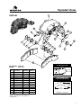
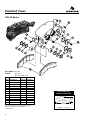
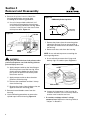
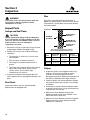
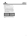
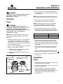
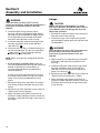
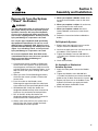
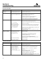
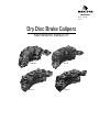
Revised 08-00
$2.50
Dry Disc Brake Calipers
Maintenance Manual 4Y
HDB 640
SCL 35
SCL 46
SCL 53
Service Notes
Before You Begin
This manual provides installation and maintenance
procedures for Meritor’s HDB 640, SCL 35, 46 and
53 Series dry disc brake calipers. Before you begin
procedures:
1. Read and understand all instructions and
procedures before you begin to service
components.
2. Read and observe all Caution and Warning
safety alerts that precede instructions or
procedures you will perform. These alerts help
to avoid damage to components, serious
personal injury, or both.
3. Follow your company’s maintenance and
service, installation, and diagnostics guidelines.
4. Use special tools when required to help avoid
serious personal injury and damage to
components.
Safety Alerts, Torque Symbol
and Notes
!
WARNING
A Warning alerts you to an
instruction or procedure
that you must follow
exactly to avoid serious
personal injury and
damage to components.
!
CAUTION
A Caution alerts you to an
instruction or procedure
that you must follow
exactly to avoid damage
to components and
possible serious personal
injury can also occur.
T
NOTE:
The torque symbol alerts
you to tighten fasteners to
a specified torque value.
A Note provides
information or
suggestions that help you
correctly service a
component.
Access Information on
ArvinMeritor’s Web Site
Additional maintenance and service information
for ArvinMeritor’s commercial vehicle systems
component lineup is also available on
ArvinMeritor’s web site at www.arvinmeritor.com.
To access information, click on Products &
Services/Tech Library Icon/HVS Publications.
The screen will display an index of publications
by type.
Additional Information
For complete maintenance and service
procedures for all disc brake calipers, call
ArvinMeritor’s Customer Service Center at
800-535-5560 to order the following publications.
• Hydraulic Dry Disc Brake Parts (Parts Book
PB-9201)
• Off-Highway Dry Disc Brakes (Publication
SP-8611)
• Technical Electronic Library on CD. Features
product and service information on most
ArvinMeritor, ZF Meritor and Meritor WABCO
components. $20. Order TP-9853.
Table of Contents
!
Asbestos and Non-Asbestos Fibers Warnings .................................................................................i
Exploded Views ...............................................................................................................................................1
HDB 640
SCL 35 Series
SCL 46 Series
SCL 53 Series
Section 1: Introduction .................................................................................................................................5
Description
Hydraulic Fluid ..............................................................................................................................................6
Identification
Section 2: Removal and Disassembly ....................................................................................................7
Removal
Brake Linings
Caliper Housing
Disassembly
Caliper
Section 3: Inspection ...................................................................................................................................10
Inspect Parts
Section 4: Prepare Parts for Assembly ................................................................................................12
Clean, Dry and Protect Parts
Section 5: Assembly and Installation ...................................................................................................13
Assembly
Installation
Remove Air from the System (“Bleed” the Brakes) ................................................................................15
Section 6: Troubleshooting .......................................................................................................................16
Brake Does Not Apply
Brake Does Not Release
Section 7: Specifications............................................................................................................................17
Torque Chart
Wear Dimensions
Hydraulic Fluid
Asbestos and Non-Asbestos Fibers
!
ASBESTOS FIBER WARNING
!
NON-ASBESTOS FIBERS WARNING
The following procedures for servicing brakes are recommended to reduce
exposure to asbestos fiber dust, a cancer and lung disease hazard. Material
Safety Data Sheets are available from Meritor.
The following procedures for servicing brakes are recommended to reduce
exposure to non-asbestos fiber dust, a potential cancer and lung disease
hazard. Material Safety Data Sheets are available from Meritor.
Hazard Summary
Hazard Summary
Because some brake linings contain asbestos, workers who service brakes must understand the
potential hazards of asbestos and precautions for reducing risks. Exposure to airborne asbestos
dust can cause serious and possibly fatal diseases, including asbestosis (a chronic lung disease)
and cancer, principally lung cancer and mesothelioma (a cancer of the lining of the chest or
abdominal cavities). Some studies show that the risk of lung cancer among persons who smoke
and who are exposed to asbestos is much greater than the risk for non-smokers. Symptoms of
these diseases may not become apparent for 15, 20 or more years after the first exposure to
asbestos.
Most recently manufactured brake linings do not contain asbestos fibers. These brake linings
may contain one or more of a variety of ingredients, including glass fibers, mineral wool, aramid
fibers, ceramic fibers and silica that can present health risks if inhaled. Scientists disagree on
the extent of the risks from exposure to these substances. Nonetheless, exposure to silica dust
can cause silicosis, a non-cancerous lung disease. Silicosis gradually reduces lung capacity
and efficiency and can result in serious breathing difficulty. Some scientists believe other types
of non-asbestos fibers, when inhaled, can cause similar diseases of the lung. In addition, silica
dust and ceramic fiber dust are known to the State of California to cause lung cancer. U.S. and
international agencies have also determined that dust from mineral wool, ceramic fibers and
silica are potential causes of cancer.
Accordingly, workers must use caution to avoid creating and breathing dust when servicing
brakes. Specific recommended work practices for reducing exposure to asbestos dust follow.
Consult your employer for more details.
Recommended Work Practices
1. Separate Work Areas. Whenever feasible, service brakes in a separate area away from other
operations to reduce risks to unprotected persons. OSHA has set a maximum allowable level of
exposure for asbestos of 0.1 f/cc as an 8-hour time-weighted average and 1.0 f/cc averaged over a
30-minute period. Scientists disagree, however, to what extent adherence to the maximum
allowable exposure levels will eliminate the risk of disease that can result from inhaling asbestos
dust. OSHA requires that the following sign be posted at the entrance to areas where exposures
exceed either of the maximum allowable levels:
DANGER: ASBESTOS
CANCER AND LUNG DISEASE HAZARD
AUTHORIZED PERSONNEL ONLY
RESPIRATORS AND PROTECTIVE CLOTHING
ARE REQUIRED IN THIS AREA
2. Respiratory Protection. Wear a respirator equipped with a high-efficiency (HEPA) filter
approved by NIOSH or MSHA for use with asbestos at all times when servicing brakes, beginning
with the removal of the wheels.
Accordingly, workers must use caution to avoid creating and breathing dust when servicing
brakes. Specific recommended work practices for reducing exposure to non-asbestos dust
follow. Consult your employer for more details.
Recommended Work Practices
1. Separate Work Areas. Whenever feasible, service brakes in a separate area away from
other operations to reduce risks to unprotected persons.
2. Respiratory Protection. OSHA has set a maximum allowable level of exposure for silica of
0.1 mg/m3 as an 8-hour time-weighted average. Some manufacturers of non-asbestos brake
linings recommend that exposures to other ingredients found in non-asbestos brake linings be
kept below 1.0 f/cc as an 8-hour time-weighted average. Scientists disagree, however, to what
extent adherence to these maximum allowable exposure levels will eliminate the risk of disease
that can result from inhaling non-asbestos dust.
Therefore, wear respiratory protection at all times during brake servicing, beginning with the
removal of the wheels. Wear a respirator equipped with a high-efficiency (HEPA) filter
approved by NIOSH or MSHA, if the exposures levels may exceed OSHA or manufacturer’s
recommended maximum levels. Even when exposures are expected to be within the maximum
allowable levels, wearing such a respirator at all times during brake servicing will help minimize
exposure.
3. Procedures for Servicing Brakes.
3. Procedures for Servicing Brakes.
a. Enclose the brake assembly within a negative pressure enclosure. The enclosure should be
equipped with a HEPA vacuum and worker arm sleeves. With the enclosure in place, use the
HEPA vacuum to loosen and vacuum residue from the brake parts.
a. Enclose the brake assembly within a negative pressure enclosure. The enclosure should be
equipped with a HEPA vacuum and worker arm sleeves. With the enclosure in place, use
the HEPA vacuum to loosen and vacuum residue from the brake parts.
b. As an alternative procedure, use a catch basin with water and a biodegradable, nonphosphate, water-based detergent to wash the brake drum or rotor and other brake parts. The
solution should be applied with low pressure to prevent dust from becoming airborne. Allow
the solution to flow between the brake drum and the brake support or the brake rotor and
caliper. The wheel hub and brake assembly components should be thoroughly wetted to
suppress dust before the brake shoes or brake pads are removed. Wipe the brake parts clean
with a cloth.
b. As an alternative procedure, use a catch basin with water and a biodegradable, nonphosphate, water-based detergent to wash the brake drum or rotor and other brake parts.
The solution should be applied with low pressure to prevent dust from becoming airborne.
Allow the solution to flow between the brake drum and the brake support or the brake rotor
and caliper. The wheel hub and brake assembly components should be thoroughly wetted to
suppress dust before the brake shoes or brake pads are removed. Wipe the brake parts clean
with a cloth.
c. If an enclosed vacuum system or brake washing equipment is not available, employers may
adopt their own written procedures for servicing brakes, provided that the exposure levels
associated with the employer’s procedures do not exceed the levels associated with the
enclosed vacuum system or brake washing equipment. Consult OSHA regulations for more
details.
c. If an enclosed vacuum system or brake washing equipment is not available, carefully clean
the brake parts in the open air. Wet the parts with a solution applied with a pump-spray bottle
that creates a fine mist. Use a solution containing water, and, if available, a biodegradable,
non-phosphate, water-based detergent. The wheel hub and brake assembly components
should be thoroughly wetted to suppress dust before the brake shoes or brake pads are
removed. Wipe the brake parts clean with a cloth.
d. Wear a respirator equipped with a HEPA filter approved by NIOSH or MSHA for use with
asbestos when grinding or machining brake linings. In addition, do such work in an area with
a local exhaust ventilation system equipped with a HEPA filter.
e. NEVER use compressed air by itself, dry brushing, or a vacuum not equipped with a HEPA
filter when cleaning brake parts or assemblies. NEVER use carcinogenic solvents, flammable
solvents, or solvents that can damage brake components as wetting agents.
4. Cleaning Work Areas. Clean work areas with a vacuum equipped with a HEPA filter or by wet
wiping. NEVER use compressed air or dry sweeping to clean work areas. When you empty
vacuum cleaners and handle used rags, wear a respirator equipped with a HEPA filter approved
by NIOSH or MSHA for use with asbestos. When you replace a HEPA filter, wet the filter with a
fine mist of water and dispose of the used filter with care.
5. Worker Clean-Up. After servicing brakes, wash your hands before you eat, drink or smoke.
Shower after work. Do not wear work clothes home. Use a vacuum equipped with a HEPA filter to
vacuum work clothes after they are worn. Launder them separately. Do not shake or use
compressed air to remove dust from work clothes.
6. Waste Disposal. Dispose of discarded linings, used rags, cloths and HEPA filters with care,
such as in sealed plastic bags. Consult applicable EPA, state and local regulations on waste
disposal.
Regulatory Guidance
References to OSHA, NIOSH, MSHA, and EPA, which are regulatory agencies in the United
States, are made to provide further guidance to employers and workers employed within the
United States. Employers and workers employed outside of the United States should consult the
regulations that apply to them for further guidance.
i
d. Wear a respirator equipped with a HEPA filter approved by NIOSH or MSHA when grinding
or machining brake linings. In addition, do such work in an area with a local exhaust
ventilation system equipped with a HEPA filter.
e. NEVER use compressed air by itself, dry brushing, or a vacuum not equipped with a HEPA
filter when cleaning brake parts or assemblies. NEVER use carcinogenic solvents, flammable
solvents, or solvents that can damage brake components as wetting agents.
4. Cleaning Work Areas. Clean work areas with a vacuum equipped with a HEPA filter or by
wet wiping. NEVER use compressed air or dry sweeping to clean work areas. When you empty
vacuum cleaners and handle used rags, wear a respirator equipped with a HEPA filter
approved by NIOSH or MSHA, to minimize exposure. When you replace a HEPA filter, wet the
filter with a fine mist of water and dispose of the used filter with care.
5. Worker Clean-Up. After servicing brakes, wash your hands before you eat, drink or smoke.
Shower after work. Do not wear work clothes home. Use a vacuum equipped with a HEPA filter
to vacuum work clothes after they are worn. Launder them separately. Do not shake or use
compressed air to remove dust from work clothes.
6. Waste Disposal. Dispose of discarded linings, used rags, cloths and HEPA filters with care,
such as in sealed plastic bags. Consult applicable EPA, state and local regulations on waste
disposal.
Regulatory Guidance
References to OSHA, NIOSH, MSHA, and EPA, which are regulatory agencies in the United
States, are made to provide further guidance to employers and workers employed within the
United States. Employers and workers employed outside of the United States should consult the
regulations that apply to them for further guidance.
Exploded Views
HDB 640
1
12
10
6
11
7
12
13
3
5
2
4
4
6
2
5
3
8
9
CYLINDER CAP HOLES
Base Model: HDB 640
Model:
HDB 640 1
Item Description
1
2
3
4
5
6
7
8
9
10
11
12
13
Housing
Back-up Ring
O-Ring
Dust Seal
Piston
O-Ring
Cylinder Cap
Cylinder Cap
Lining Assembly
End Plate
End Plate Bolt
Bleeder Screw
Plug
Sequence
Quantity Number*
1
6
6
6
6
3
1
2
2
4
8
3
1
00100
00110
00120
00130
00140
00150
00160
00170
00180
00190
00200
00210
00230
2.000"
(50.80 mm)
0.442" DIA.
(11.23 mm)
BRAKE LINING SHAPE
AND MAJOR DIMENSIONS
5.09"
(129.2
9 mm)
13.89"
(352.81 mm)
THICKNESS = 1.06" (26.92 mm)
*Sequence numbers as they appear in the Bill of
Material available from the equipment
manufacturer.
1
Exploded Views
SCL 35 Series
Base Model: SCL 35
Models:
SCL 35 1
SCL 35 5
Item Description
1
2
3
4
5
6
7
8
9
10
11
12
13
Housing
Back-up Ring
O-Ring
Dust Seal
Piston
O-Ring
Cylinder Cap
Cylinder Cap
Lining Assembly
End Plate
End Plate Bolt
Bleeder Screw
Plug
Sequence
Quantity Number*
1
6
6
6
6
3
1
2
2
4
8
2
1
00100
00110
00120
00130
00140
00150
00160
00170
00180
00190
00200
00210
00220
*Sequence numbers as they appear in the Bill of
Material available from the equipment
manufacturer.
2
BRAKE LINING SHAPE
AND MAJOR DIMENSIONS
5.18"
(131.57
mm)
15.536"
(394.61 mm)
THICKNESS = 1.06" (26.92 mm)
Exploded Views
SCL 46 Series
Base Model: SCL 46
Model:
SCL 46
Item Description
1
2
3
4
5
6
7
8
9
10
11
12
13
Housing
Back-up Ring
O-Ring
Dust Seal
Piston
O-Ring
Cylinder Cap
Cylinder Cap
Lining Assembly
End Plate
End Plate Bolt
Bleeder Screw
Plug
Sequence
Quantity Number*
1
6
6
6
6
3
1
2
2
4
8
2
1
00100
00110
00120
00130
00140
00150
00160
00170
00180
00190
00200
00210
00220
BRAKE LINING SHAPE
AND MAJOR DIMENSIONS
5.09"
(129.2
9 mm)
13.89"
(352.81 mm)
THICKNESS = 1.06" (26.92 mm)
*Sequence numbers as they appear in the Bill of
Material available from the equipment
manufacturer.
3
Exploded Views
SCL 53 Series
Base Model: SCL 53
Models:
SCL 53
SCL 53 1, SCL 53 2
Item Description
Sequence
Quantity Number*
1
2
3
4
5
6
7
8
9
10
Housing
Back-up Ring
O-Ring
Dust Seal
Piston
O-Ring
Cylinder Cap
Cylinder Cap
Lining Assembly
End Plate
1
6
6
6
6
3
1
2
2
4
00100
00110
00120
00130
00140
00150
00160
00170
00180
00190
11
12
13
End Plate Bolt
Plug
Bleeder Screw
8
1
3
00200
00210
00220
*Sequence numbers as they appear in the Bill of
Material available from the equipment
manufacturer.
4
BRAKE LINING SHAPE
AND MAJOR DIMENSIONS
5.18"
(131.57
mm)
15.536"
(394.61 mm)
THICKNESS = 1.06" (26.92 mm)
Section 1
Introduction
Description
Figure 1.2
The HDB 640, SCL 35, 46 and 53 Series dry disc
brake calipers are intended only for service use on
hydraulic brake systems. All calipers mount to a
fixed position on fixed position discs. Figures 1.1,
1.2, 1.3 and 1.4.
One or two calipers can be used on a disc. Install
the SCL 35 and SCL 46 calipers at the 3 or 9
o’clock positions. Install the HDB 640 and SCL 53
calipers at the 3, 9, or 12 o’clock positions.
The calipers are designed to be used on the
following size discs:
SCL 35
Model
Disc Size/Inches (millimeters)
HDB 640
18.50" (470 mm) in a 25" rim (635 mm)
SCL 35
22.50" (571 mm) in a 29" rim (737 mm)
SCL 46
18.75" (476 mm) in a 25" rim (635 mm)
SCL 53
26" (660 mm) in a 33" rim (838 mm)
28" (711 mm) ina 35" rim (889 mm)
Figure 1.3
Figure 1.1
SCL 46
Figure 1.4
HDB 640
SCL 53
5
Section 1
Introduction
Hydraulic Fluid
!
WARNING
Use only the type of hydraulic fluid specified by
the equipment manufacturer. Do not use or mix
different types of hydraulic fluid. Using incorrect
hydraulic fluid will damage the rubber parts of
the caliper. Loss of braking control, serious
personal injury and damage to components
can result.
Do not reuse hydraulic fluid. Used fluid can be
contaminated and can cause incorrect operation.
Serious personal injury and damage to
components can result.
The HDB 640, SCL 35, 46, and 53 brake systems
use one of two types of hydraulic fluid:
Petroleum Base
Hydraulic Fluid
(Mineral Oil)
Non-Petroleum Base
Hydraulic Fluid
(Automotive Brake Fluid)
Example:
Meets MIL-H-5606
specifications
Example:
Glycol DOT 3, meets SAE
J-1703 specifications
Identification
An assembly number located on the side of the
caliper that is opposite from the mounting plate
identifies older assemblies. An identification tag
located on the inside radius of the caliper
identifies more recent assemblies. Figure 1.5.
Figure 1.5
ID TAG (RECENT
ASSEMBLIES):
BRAKE SPECIFICATION NUMBER:__________
MANUFACTURING PLANT:_________________
6
Section 2
Removal and Disassembly
!
WARNING
To prevent serious eye injury, always wear safe
eye protection when you perform vehicle
maintenance or service.
Removal
!
WARNING
Park the vehicle on a level surface. Block the
wheels to prevent the vehicle from moving.
Support the vehicle with safety stands. Do not
work under a vehicle supported only by jacks.
Jacks can slip and fall over. Serious personal
injury can result.
1. Park the vehicle on a level surface.
2. Place blocks under the wheels not being
serviced to keep the vehicle from moving.
3. If necessary, raise the vehicle so that the
wheels to be serviced are off the ground.
Support the vehicle with safety stands.
4. Remove the wheel.
Brake Linings
1. Remove the bolts that fasten the end plates to
one side of the caliper housing. Remove the end
plates. Replace worn or damaged end plates.
2. Loosen the bleeder screws in the caliper
housings to release hydraulic pressure.
3. Use a piece of wood to pry the linings away
from the disc and push the pistons completely
into the housing. Tighten the bleeder screws.
4. Remove the linings from the housing. Inspect
the linings. Refer to “Linings and End Plates” in
Section 3.
Caliper Housing
!
WARNING
Housings are very heavy. Support the housing
during removal and installation. Serious personal
injury or damage to caliper can occur if a caliper
housing falls.
NOTE: To lighten caliper weight, remove the
brake linings from the caliper before you remove
the caliper from the vehicle.
1. Disconnect the brake line from the inlet fitting.
Put a plug in the brake line and the inlet fitting
to prevent contamination of the system.
2. Remove the linings as described earlier in this
section.
3. Remove the fasteners that hold the caliper
housing onto the mounting bracket. Remove
the caliper housing from the mounting bracket.
• If shims are used between the housing and
mounting bracket: Mark the shim positions.
Disassembly
Caliper
1. Remove the inlet fitting and the O-ring from
the cylinder cap. Drain the hydraulic fluid from
the caliper. Discard the fluid.
2. Clean the outside of the housing with isopropyl
alcohol. Dry the housing with a clean cloth.
3. If installed, remove the bolts that hold the end
plates on the housing. Remove the end plates
and linings.
• If you are only changing the linings: Refer to
“Linings” in Section 5.
7
Section 2
Removal and Disassembly
4. Remove the pistons from the side of the
housing opposite the mounting plate
according to the following procedure:
A. Use a C-clamp to hold a 0.50 inch (12.7
mm) block of wood against three pistons
on the mounting side of the housing. Make
sure the C-clamp is not in the area in front
of the piston bore. Figure 2.1.
Figure 2.1
Figure 2.2
HDB 640 Cylinder Cap Holes
2.000"
(50.80 mm)
0.442" DIA.
(11.23 mm)
C-CLAMP
7. Remove the pistons from the mounting plate
side of the housing. Push on the cap ends of
the pistons to force them out of the disc side of
the housing.
AIR GUN
!
WOOD
BLOCK
8. Remove the dust seals from the housing.
PISTON
WARNING
Do not put your hand in front of the pistons when
you force the pistons out of the housing. Serious
personal injury can occur.
B. Apply compressed air to the inlet fitting to
force the pistons out of the housing. If one
piston comes out before the other piston,
put a piece of wood in front of the piston
that comes out first.
NOTE: Use a soft tool to prevent scratching the
housing and grooves.
9. Use a soft tool to remove the O-rings and
backup rings. Discard the parts. Figure 2.3.
Figure 2.3
O-RING
C. Apply compressed air to force the other
piston out of the housing.
D. Remove the wood block and the C-clamp
from the housing.
BACK-UP RING
E. Remove the pistons from the bores that are
opposite from the mounting plate.
5. Remove the two bleeder screws from the
housing.
6. Use the following procedures to remove the
cylinder caps from the housing. Figure 2.2.
10. Inspect the ring grooves in the housing for
scratches and rust. Use a fine emery cloth to
remove small scratches and rust.
• If scratches are deep, or there is a large
amount of rust: Replace the housing. Refer to
“Caliper” in Section 3.
8
Section 2
Removal and Disassembly
11. Inspect the pistons and bores for scratches
and rust. Use a fine emery cloth to remove
small scratches and rust.
• If scratches are deep, there is a large amount
of rust, or the pistons and bores are damaged:
Replace the components. Refer to “Caliper” in
Section 3.
9
Section 3
Inspection
!
Disc
WARNING
To prevent serious eye injury, always wear safe
eye protection when you perform vehicle
maintenance or service.
Inspect Parts
If the disc is worn beyond the specifications in
Figure 3.1, replace the disc. Also refer to the vehicle
manufacturer’s specifications that may be different
from those below.
Figure 3.1
Linings and End Plates
!
CAUTION
Always replace both linings with specified parts.
If you only replace one lining, damage to the disc
can occur. If you use non-Meritor parts, incorrect
brake operation can occur. Damage to
components can result.
MAXIMUM
DISC WEAR
1. Remove the linings. Inspect the linings for wear
and damage. Replace damaged linings.
the backplate.
• Each lining has a different thickness.
• The linings are contaminated with oil or
MINIMUM DISC
THICKNESS
MAXIMUM DISC
WEAR EACH SIDE
ORIGINAL DISC
THICKNESS
Typical Section Through Disc Showing
Recommended Maximum Wear Limits
2. Replace the linings if you find the following
conditions:
• The thickness is 0.125-inch (3.2 mm) from
;;;;
;;;;
;;;;
;;;;
;;;;
;;;;
;;;;
;;;;
;;;;
;;;;
Original Disc
Thickness
Maximum
Disc Wear
Each Side
Minimum
Disc Thickness
HDB 640
1.574 inch
(40 mm)
0.06 inch
(1.5 mm)
1.450 inch
(36.83 mm)
SCL 35,
46 and 53
0.625 inch
(15.875 mm)
0.06 inch
(1.5 mm)
0.50 inch
(12.7 mm)
Model
grease.
• The linings have large or deep cracks. Small,
tight cracks (heat checks) on the lining’s
surface, which are caused by high
temperatures, are normal.
3. Inspect the end plate and end plate bolts for
wear. Replace worn or damaged end plates and
bolts.
Dust Seals
Check that the dust seals are soft and flexible.
Replace worn or damaged seals.
Caliper
1. Inspect the pistons, housing bores and O-ring
grooves. Use a fine emery cloth to remove
scratches or corrosion. Replace worn or
damaged components. Replace components that
are heavily corroded or have large scratches.
2. Check the pistons for correct operation. Replace
the piston and housing if a piston is not straight
in the bore.
3. If fluid leaks at a piston, disassemble the caliper.
Inspect the piston, bore, O-rings and the back-up
rings. Service as necessary.
4. Measure the outer diameter of the piston.
Replace the piston if the outer diameter is less
than 2.995 inches (76.07 mm).
5. Measure the outer diameter of the housing bore.
Replace the housing if the diameter exceeds
3.003 inches (76.28 mm).
10
Section 3
Inspection
6. Inspect inlet fitting and O-ring for damage.
Replace O-ring if necessary.
7. Inspect the linings as described earlier in this
section.
8. Inspect caliper ports and end plate bolt holes
for thread damage. Refer to the table below.
A. Use the appropriate taps lubricated with
light oil to inspect tapped holes for thread
damage and to clean minor thread damage.
B. Replace components with thread damage
that you cannot repair. Use a thread tap to
repair minor damage.
Area to Inspect
Tap Size to Use
Bleeder ports
0.4375-20 UNF
End plate bolt holes
0.6250-11 UNC
Inlet port
0.5000-20 UNF
9. Discard all back-up rings, O-rings and dust
boots. Install new ones when you assemble the
caliper.
11
Section 4
Prepare Parts for Assembly
!
WARNING
3. Use a wire brush to clean fastener and fitting
threads.
To prevent serious eye injury, always wear safe
eye protection when you perform vehicle
maintenance or service.
4. Remove mud and dirt on the linings. Replace
all linings contaminated with oil or grease.
Clean, Dry and Protect Parts
Dry Parts Immediately
After Cleaning
!
WARNING
Solvent cleaners can be flammable, poisonous
and cause burns. Examples of solvent cleaners are
carbon tetrachloride, emulsion-type cleaners and
petroleum-based cleaners. To avoid serious
personal injury when you use solvent cleaners,
you must carefully follow the manufacturer’s
product instructions and these procedures:
• Wear safe eye protection.
• Wear clothing that protects your skin.
• Work in a well-ventilated area.
• Do not use gasoline, or solvents that contain
gasoline. Gasoline can explode.
• You must use hot solution tanks or alkaline
solutions correctly. Follow the manufacturer’s
instructions carefully.
Cleaning Parts
!
CAUTION
Do not use hot solution tanks or water and
alkaline solutions to clean ground or polished
parts. Damage to parts will result.
1. Use a cleaning solvent or kerosene or diesel
fuel to clean ground or polished metal parts
or surfaces. Examples of ground or polished
parts are the piston and the piston bore in
the caliper.
2. Use a cleaning solvent or a weak alkaline
solution in a hot solution tank to clean rough
metal parts. If you use a hot solution tank,
follow the instructions below.
A. Leave the parts in the tank until they are
completely cleaned and heated.
B. Remove the parts from the tank.
C. Wash the parts with water until you remove
the alkaline solution.
12
1. Use soft, clean paper or cloth rags, or
compressed air to completely dry parts
immediately after you clean them.
2. Carefully inspect all parts for wear or damage
before you assemble them.
3. Repair or replace worn or damaged parts.
Apply Corrosion Protection
1. Apply a thin layer of grease to cleaned, dried
parts. Be careful that you do not apply the
grease to the linings or rotor.
2. If you will store the parts, apply a special
material, which prevents corrosion and rust, to
all surfaces. Store parts inside special paper or
other material that prevents rust and corrosion.
Section 5
Assembly and Installation
!
WARNING
To prevent serious eye injury, always wear safe
eye protection when you perform vehicle
maintenance or service.
Assembly
NOTE: Take care when you install the O-ring, so
that the cylinder cap threads don’t cut the O-ring.
4. Install a new O-ring into the cylinder cap
groove between the threads and flange.
Caliper
!
3. Install a new dust seal into the top groove of
the bore. Do not use silicone grease on the dust
seal. Figure 5.1.
CAUTION
Only use specified components when you
assemble the caliper. If you install the incorrect
components, the caliper will not operate
correctly. If you use non-Meritor parts, incorrect
brake operation can occur. Damage to
components can result.
NOTE: You must lubricate the O-rings, back-up
rings, pistons and bores before you can install
the pistons.
NOTE: Apply extra grease to the O-ring before
you install a cylinder cap to help prevent the
O-ring from catching on cylinder cap threads.
5. Apply extra grease to the O-ring. Install the
cylinder cap into the caliper housing. Tighten
the cylinder cap to the following specificaitons.
Model
Torque (Minimum)
HDB 640
500 lb-ft (680 N•m)
SCL 35, SCL 46, SCL 53
75 lb-ft (100 N•m)
1. Lubricate all pistons, bores, O-rings and backup rings with silicone grease such as Dow
Corning DC-4 or equivalent. If silicone grease is
not available, use the same type of fluid that is
used in the brake system.
6. Install the pistons into the housing, with the
hole in the piston toward the lining. Push the
pistons into the housing from the lining side of
the housing. Check that the pistons are straight
in the bores.
2. Install a new O-ring and a back-up ring into the
groove in the middle of the bore.
7. Push each piston into the bore until the top of
each piston is even with the top of the dust
seal.
A. Install the back-up ring toward the lining
side of the bore. Figure 5.1.
B. Install the O-ring behind the back-up ring.
Figure 5.1.
8. Install the bleeder screws into the housing and
tighten them to 100-180 lb-in (11.3-20.3 N•m).
T
9. Install the O-ring and the inlet fitting into the
cylinder cap.
Figure 5.1
Install the back-up
ring toward lining
side of bore.
Install the O-ring behind
the back-up ring.
Caliper
O-RING
1. Place blocks under the wheels of the vehicle to
keep the vehicle from moving.
2. If shims are used, put the shims in the position
marked during removal.
BACKUP RING
BACK-UP RING
AND O-RING
GROOVE
DUST SEAL
Installation
DUST SEAL
GROOVE
3. Place the caliper housing on the mounting
bracket. Install the fasteners that hold the
caliper onto the bracket. Tighten the fasteners
to the torque specified by the equipment
manufacturer.
13
Section 5
Assembly and Installation
!
WARNING
Take care when you use Loctite® to avoid
serious personal injury. Follow the manufacturer’s
instructions to prevent irritation to the eyes
and skin.
4. Install the brake linings into the caliper
housing, with the metal backing plate against
the pistons and not toward disc. Apply Loctite®
271 or equivalent to the threads of the bolts
that fasten the end plates to the housing.
5. Install the end plates onto the housing. Install
the bolts and tighten them to 165-210 lb-ft
(224-285 N•m). T
6. Check that the housing is installed correctly on
the mounting bracket. The disc must be within
+ 0.06 inches (+ 1.5 mm) of being centered
between the lining end plates.
NOTE: Shims must be steel, and ground flat and
parallel.
• If it is necessary to install a shim: Install the
!
CAUTION
Replace the linings on both brakes of a single
axle at the same time. Use Meritor parts. The use
of non-Meritor parts can damage the discs and
affect brake operation.
1. Place blocks under the wheels of the vehicle to
keep the vehicle from moving.
2. Install the linings in the caliper housing with
the metal backing plate against the pistons and
not toward disc.
!
WARNING
Take care when you use Loctite® to avoid serious
personal injury. Follow the manufacturer’s
instructions to prevent irritation to the eyes
and skin.
3. Apply Loctite® 271 or equivalent to the threads
of the bolts and fasten the end plates to the
housing.
shim either between the housing and mounting
bracket, or between the hub and disc, to
increase outboard clearance and decrease
inboard clearance.
4. Install the end plates onto the housing. Install
the bolts and tighten them to 165-210 lb-ft
(224-285 N•m). Ensure that the linings move
freely in the housing. T
A shim must cover the entire hub or housing
mounting surface, and the linings must move
freely in the housing and between the end
plates.
5. Remove the air from the brake system. Refer to
“Remove Air From the System,” below.
7. Remove the plugs from the brake line and the
inlet fitting. Connect the brake line to the inlet
fitting.
8. Remove the air from the brake system. Refer to
“Remove Air from the System.”
9. Apply and release the brakes three times to
ensure the caliper operates correctly. Check for
fluid leaks. Check that the linings move freely in
the caliper.
14
Linings
6. Apply and release the brakes three times to
ensure the caliper operates correctly. Check for
fluid leaks. Ensure that the linings move freely
in the housing.
Section 5
Assembly and Installation
Remove Air from the System
(“Bleed” the Brakes)
!
WARNING
You must bleed the brakes to remove all air from
the system, when you loosen any brake system
hydraulic connection. Air can prevent hydraulic
pressure from applying the brakes properly and
can increase stopping distance. Serious personal
injury and damage to components can result.
5. When you complete a bleeder screw: Go to
the next closest bleeder screw on the same
caliper.
6. When you complete a caliper: Go to the next
closest caliper on the same wheel.
7. When you complete a wheel: Go to the
farthest bleeder screw on the next closest
wheel.
8. Follow the instructions below to bleed the
brakes.
Use only the type of hydraulic fluid specified by
the equipment manufacturer. Do not use or mix
different types of hydraulic fluid. Using incorrect
hydraulic fluid will damage the rubber parts of the
caliper. Loss of braking control, serious personal
injury and damage to components can result.
1. Slowly apply low hydraulic pressure to the
caliper. Loosen the bleeder screw.
Do not reuse hydraulic fluid. Used fluid can be
contaminated and can cause incorrect operation.
Serious personal injury and damage to
components can result.
3. Tighten the bleeder screw to 100-180 lb-in
(11.3-20.3 N•m). Release the pressure to the
caliper. T
1. Check that the master cylinder is filled to the
correct level with hydraulic fluid specified by
the component manufacturer. Keep the master
cylinder filled when you bleed the brakes, so air
does not enter the system through the master
cylinder.
2. When you have finished bleeding the brakes,
check that the master cylinder is filled to the
correct level.
3. Put a clear tube on the bleeder screw.
Submerge the opposite end of the tube into a
clear container of the specified hydraulic fluid.
• HDB 640 and SCL 53 dry disc brakes are
Full Hydraulic Systems
2. Continue to apply pressure until there are no
air bubbles in the hydraulic fluid.
4. Check for fluid leaks.
Air Hydraulic or Mechanical
Actuator Systems
1. Apply the brake pedal. Loosen the bleeder
screw.
2. Tighten the bleeder screw 100-180 lb-in
(11.3-20.3 N•m) before you release the brake
pedal so that air does not enter the system.
T
3. Repeat until there are no air bubbles in the
hydraulic fluid when you apply the brake
pedal and loosen the bleeder screw.
4. Check for fluid leaks.
designed to bleed correctly when mounted at
the three, nine and twelve o’clock positions.
• SCL 35 and SCL 46 dry disc brakes are
designed to bleed correctly when mounted in
the three and nine o’clock positions.
4. Always start at the point in the system that is
farthest from the master cylinder and work
back toward the master cylinder.
15
Section 6
Troubleshooting
Brake Does Not Apply
Condition
Possible Causes
Correction
There is no pressure to
the brake.
1. Empty fluid reservoir
1. Fill the reservoir to the correct level with specified fluid.
2. Damaged hydraulic system
2. Repair the hydraulic system.
Piston does not move.
1. No pressure to brake
1. Fill the reservoir to the correct level with specified fluid.
2. Piston not straight in the bore
2. If piston diameter is less than 2.995 inches
(76.073 mm): Replace piston.
If caliper bore diameter is greater the 3.003 inches
(76.276 mm): Replace the caliper housing.
If tapered lining wear exists: Replace the linings. Remove
dirt and other material between the lining and piston.
Brake leaks.
1. Loose bleeder screw
1. Tighten the bleeder screw to 100-180 lb-in. (11.3-20.3 N•m).
If the leak continues, replace the bleeder screw.
2. Loose inlet fitting
2. Tighten the inlet fitting. If the leak continues, replace the O-ring.
3. Damaged inlet fitting
3. Replace the inlet fitting.
4. Worn or damaged piston,
housing bore, O-rings
and/or back-up rings
4. Inspect the piston and housing bore for wear and damage.
Service as necessary. Replace O-rings and backup rings.
5. Loose cylinder cap
5. Replace the O-ring. For HDB 640, tighten the cylinder cap to
500 lb-ft (680 N•m) minimum.
For SCL 35, 46 and 53, tighten the cylinder cap to 75 lb-ft
(100 N•m) minimum.
Linings are damaged.
1. Lining thickness less than
0.125 inch (3.2 mm)
1. Replace the linings.
2. Lining wear not even
2. Inspect the piston. Service the piston as necessary.
If caliper bore diameter is more than 3.003 inches
(76.276 mm): Replace caliper.
Inspect the housing for clogged fluid passages.
Service as necessary. If end plates are worn, replace them.
3. Cracked or broken linings
3. Replace the linings.
4. Oil or grease on linings
4. Replace the linings.
Brake Does Not Release
Condition
Possible Causes
Correction
Vehicle does not move.
1. Parking brake applied
1. Release the parking brake.
2. Damaged hydraulic system
2. Repair the hydraulic system.
1. More than 3 psi (.2 bar)
pressure applied when
brakes are released
1. Repair the hydraulic system so that pressure is less than 3 psi
(.2 bar) when the brakes are released. Bleed the brakes.
2. Vehicle or equipment not
operated correctly
2. Advise the operator on correct vehicle or equipment
operation.
3. Piston not straight in the bore
3. If piston diameter is less than 2.995 inches
(76.073 mm): Replace piston.
Brakes drag.
If caliper bore diameter is more than 3.003 inches
(76.276 mm): Replace the caliper housing.
If tapered lining wear exists: Replace linings. Remove dirt and
other material from the lining and piston.
16
Section 7
Specifications
Torque Chart
Component
Torque
End plate bolts
165-210 lb-ft (224-285 N•m)
Caliper mounting
bracket fasteners
Vehicle manufacturer’s
specification
Bleeder screws
100-180 lb-in (11.3-20.3 N•m)
Cylinder cap
HDB 640
SCL 35, 46 and 53
500 lb-ft (680 N•m) minimum
75 lb-ft (100 N•m) minimum
Wear Dimensions*
Component
When to Replace
Disc
Wear exceeds maximum of
0.06 in (1.5 mm) per side
Housing
Bore diameter exceeds
3.003 in (76.276 mm)
Linings
Thickness is less than 0.125 in
(3.2 mm) from back plate
Piston
Diameter worn to less than
2.995 in (76.073 mm)
Hydraulic Fluid*
Component
Example
Petroleum Base Hydraulic
Fluid (Mineral Oil)
Meets MIL-H-5606
specifications
Non-Petroleum Base
Hydraulic Fluid
(Automotive Brake Fluid)
Glycol DOT 3, meets
SAE J-1703 specifications
*See fluid and specification recommendations of equipment
manufacturer.
17
Notes
Notes
Notes
Information contained in this publication was in effect at the time the publication was approved for printing and is
subject to change without notice or liability. ArvinMeritor Commercial Vehicle Systems reserves the right to revise the
information presented or discontinue the production of parts described at any time.
ArvinMeritor, Inc.
Commercial Vehicle Systems
2135 West Maple Road
Troy, MI 48084 U.S.A.
248-435-1085
800-535-5560 (North America only)
www.arvinmeritor.com
Meritor do Brasil Ltda.
Av. João Batista, 824
06097-900 Osasco-SP
BRAZIL
(55-11) 7084-6510
Fax: (55-11) 7084-6600
Meritor Commercial Vehicle Systems Saint-Etienne S.A.
4, Rue Jean Servanton
Boite Postale 656
42042 Saint Etienne Cedex 1
FRANCE
(33) 477.92.88.00 Fax: (33) 477.92.88.93
Copyright 2000 ArvinMeritor, Inc.
All Rights Reserved
Maintenance Manual 4Y
Revised 08-00
47865/24240
Printed in the U.S.A.