1
®
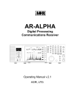
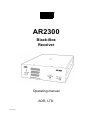
AR2300
Black-Box
Receiver
Operating manual
AOR, LTD.
Feb.21, 2011
Table of contents
1.
2.
Introduction
Introduction
1-2
Caring for your radio
------------------------------------------------------------------
7
1-3
Included in this package
------------------------------------------------------------------
8
1-4
Front panel
1-5
Rear
PC control
5
------------------------------------------------------------------------------
12
------------------------------------------------------------------------------------------
13
------------------------------------------------------------------------------------------
14
2-1
System requirements
2-2
USB (Universal Serial Bus)
------------------------------------------------------
14
2-2-1
------------------------------------------------------
14
------------------------------------------
17
------------------------------------------------------------------
USB Driver installation
AR2300 control software installation
14
2-3-1
Starting the program
------------------------------------------------------
17
2-3-2
In case of difficulty
------------------------------------------------------
18
------------------------------------------------------------------------------
19
------------------------------------------------------------------------------
20
3-1
Command format ------------------------------------------------------------------------------
20
3-2
Response format ------------------------------------------------------------------------------
20
3-3
Power on the AR2300
------------------------------------------------------------------
21
3-3-1
Wake up
------------------------------------------------------------------
21
3-3-2
Wake up ID set up
2-4
LAN (optional)
Control commands
3-4
------------------------------------------------------
21
Power off the AR2300
------------------------------------------------------------------
21
3-4-1
Standby mode
------------------------------------------------------------------
21
3-4-2
Sleep timer
------------------------------------------------------------------
21
------------------------------------------------------------------------------
21
3-5
Audio gain
3-6
Frequency/memory channel up/down
3-7
Step frequency
3-8
3-9
1
------------------------------------------------------------------------------
5
1-1
2-3
3.
------------------------------------------------------------------------------------------
------------------------------------------
21
------------------------------------------------------------------------------
21
Receive modes, IF bandwidth, AUTO mode ------------------------------------------
22
3-8-1
Command description
------------------------------------------------------
22
3-8-2
Simple mode
------------------------------------------------------------------
22
3-8-3
Advanced mode ------------------------------------------------------------------
22
3-8-4
Auto mode
23
3-8-5
Destination setting
Decode assist function
-----------------------------------------------------------------------------------------------------------------------
23
------------------------------------------------------------------
23
3-9-1
Auto notch (Notch)
------------------------------------------------------
23
3-9-2
Noise reduction (NR)
------------------------------------------------------
24
3-9-3
Noise blanker (NB)
------------------------------------------------------
24
3-9-4
Voice inversion descrambler
------------------------------------------
24
3-9-5
IF shift ------------------------------------------------------------------------------
24
3-9-6
CW pitch frequency
25
------------------------------------------------------
3-9-7
Automatic gain control (AGC)
-----------------------------------------
25
3-9-8
Automatic frequency control (AFC) -----------------------------------------
25
3-9-9
Tone squelch (CTCSS)
------------------------------------------------------
25
3-9-10
Digital code squelch (DCS)
------------------------------------------
26
3-9-11
DTMF code
------------------------------------------------------------------
26
3-9-12
De-emphasis
------------------------------------------------------------------
26
Squelch ------------------------------------------------------------------------------------------
27
3-10-1
Level squelch
------------------------------------------------------------------
27
3-10-2
Voice squelch
------------------------------------------------------------------
27
3-11
RF amplifier, attenuator
------------------------------------------------------------------
27
3-12
Antenna select
------------------------------------------------------------------------------
27
3-10
3-12-1
3-13
3-14
4.
Antenna select programming
------------------------------------------
28
S-meter ------------------------------------------------------------------------------------------
28
3-13-1
Signal level
------------------------------------------------------------------
28
3-13-2
Auto signal level ------------------------------------------------------------------
29
Audio recorder control
------------------------------------------------------------------
29
3-14-1
Control relay status
------------------------------------------------------
29
3-14-2
Control relay status report ------------------------------------------------------
29
3-15
Manual RF gain ------------------------------------------------------------------------------
29
3-16
RF filter bandwidth for A/D converter
30
3-17
RF band pass filter (for below 25MHz reception)
-----------------------------------------------------------------------
30
Receive commands
------------------------------------------------------------------------------
30
4-1
VFO mode
------------------------------------------------------------------------------
30
4-2
Search mode (normal search mode)
------------------------------------------
31
4-2-1
Search bank
------------------------------------------------------------------
31
4-2-2
Pass frequency
------------------------------------------------------------------
32
4-2-3
Normal search setting format
4-2-4
Search frequency list
------------------------------------------
33
------------------------------------------------------
33
4-3
FFT Search
------------------------------------------------------------------------------
33
4-4
Memory Channel ------------------------------------------------------------------------------
34
4-4-1
Memory read mode
------------------------------------------------------
34
4-4-2
Memory data setting
------------------------------------------------------
35
4-4-3
Memory bank resizing
------------------------------------------------------
35
4-4-4
Delete memory channel
------------------------------------------------------
35
4-4-5
Delete memory bank
------------------------------------------------------
36
Scan
------------------------------------------------------------------------------------------
36
4-5-1
Start scan
36
4-5-2
Memory data setting
4-5-3
Memory pass
4-5
4-6 Select scan
-----------------------------------------------------------------------------------------------------------------------
36
------------------------------------------------------------------
36
------------------------------------------------------------------------------------------
37
2
4-7
5
5-2
7
8
Start select scan ------------------------------------------------------------------
37
4-6-2
Select scan setting
37
------------------------------------------------------
Duo frequency / tri frequency receive
------------------------------------------
4-7-1
Duo frequency receive (duo band receive)
4-7-2
Duo frequency receive (frequency offset receive mode)
4-7-3
Tri frequency receive
Priority receive
------------------------------
37
37
------
38
------------------------------------------------------
39
------------------------------------------------------------------
39
------------------------------------------------------------------------------
39
Other receive commands
5-1
6
4-6-1
5-1-1
Priority setup
------------------------------------------------------------------
39
5-1-2
Starting priority
------------------------------------------------------------------
39
Step adjust
-----------------------------------------------------------------------------
Spectrum display commands
40
------------------------------------------------------------------
40
6-1
Start frequency
------------------------------------------------------------------------------
40
6-2
End frequency
------------------------------------------------------------------------------
40
6-3
Center frequency ------------------------------------------------------------------------------
40
6-4
Span frequency
------------------------------------------------------------------------------
40
6-5
Spectrum step frequency ------------------------------------------------------------------
40
6-6
Marker frequency ------------------------------------------------------------------------------
41
6-6-1
Marker frequency setup
------------------------------------------------------
41
6-6-2
Marker frequency / level auto output ------------------------------------------
41
6-6-3
Transfer the marker frequency to receive frequency
------------------
41
------------------------------------------------------------------
41
6-7
Spectrum data output
6-8
High speed spectrum data output
------------------------------------------------------
41
------------------------------------------------------------------
42
7-1
Activate the video monitor function ------------------------------------------------------
42
7-2
Frequency shift reverse
------------------------------------------------------------------
42
I/Q output commands
------------------------------------------------------------------------------
42
8-1
------------------------------------------------------------------------------
42
------------------------------------------------------------------------------
43
Video monitor commands
I/Q bandwidth
9
Data editor commands
10
Configuration commands of other parameters
------------------------------------------
44
10-1
Selecting interface
------------------------------------------------------------------
44
10-2
Communication speed
------------------------------------------------------------------
44
10-3
Flow control
------------------------------------------------------------------------------
44
11 LAN (Local Area Network) control commands ------------------------------------------------------
45
3
11-1
Readout settings from the optional LAN-box -------------------------------------------
45
11-2
Write settings to the LAN-box
-------------------------------------------------------
45
11-3
IPv4 address
-------------------------------------------------------------------------------
45
11-4
Mask address
-------------------------------------------------------------------------------
45
11-5
Gateway address -------------------------------------------------------------------------------
45
11-6
DHCP client function
46
-------------------------------------------------------------------
12
13
11-7
PING response
------------------------------------------------------------------------------
46
11-8
TCP port number ------------------------------------------------------------------------------
46
11-9
UDP port number ------------------------------------------------------------------------------
46
11-10
MAC address
------------------------------------------------------------------------------
46
11-11
Username
------------------------------------------------------------------------------
46
11-12
Password
------------------------------------------------------------------------------
47
SD (SDHC) card commands
------------------------------------------------------------------
47
12-1
Property of SD card
------------------------------------------------------------------
47
12-2
Display file directory
------------------------------------------------------------------
47
12-3
Delete data file
------------------------------------------------------------------------------
47
12-4
Format card
------------------------------------------------------------------------------
47
12-5
Write data to SD card
------------------------------------------------------------------
47
12-6
Read data from SD card
------------------------------------------------------------------
47
12-7
Squelch skip
------------------------------------------------------------------------------
48
12-8
Start/Stop recording
------------------------------------------------------------------
48
12-9
Start/Stop playback
------------------------------------------------------------------
48
12-10
Recording status ------------------------------------------------------------------------------
48
Other control commands ------------------------------------------------------------------------------
49
13-1
49
Receiver status
------------------------------------------------------------------------------
13-1-1
Receiver status
------------------------------------------------------------------
49
13-1-2
Receiver status auto report------------------------------------------------------
49
13-2
Product version
------------------------------------------------------------------------------
49
13-3
Reset
------------------------------------------------------------------------------------------
50
13-4
Flash memory
------------------------------------------------------------------------------
50
14.
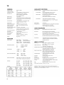
Specifications
------------------------------------------------------------------------------------------
51
15.
I/Q digital output in details for developers ------------------------------------------------------
52
16.
Reset
58
17.
Firmware upgrade
-------------------------------------------------------------------------------
59
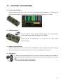
18.
Optional accessories
-------------------------------------------------------------------------------
62
19.
Limited warranty (USA only)
-------------------------------------------------------------------------------------------------------
-------------------------------------------------------------------
64
4
1. Introduction
1-1 Introduction
Thank you for purchasing the AR2300 Digital Processing Communications receiver.
As the successor to the SR2200 “black box” receiver, the AR2300 is designed using the very latest
technology to ensure the highest levels of performance and reliability. To obtain the best possible
results from your AR2300, we strongly recommend that you read this manual and familiarize yourself
with the receiver.
Although carefully designed, this receiver (like all receivers) suffers from a degree of internal noises
known as spurious emission. They are a product of the receiver’s circuitry, and therefore, their
presence does not represent a problem. Other apparent problems may be due to accidental
misoperation of the receiver. If you believe there is a problem, carefully read the manual before
deciding to contact your dealer for advice or service.
It is acknowledged that sections of this manual are repetitive, this is to enable the manual to be used
as a reference book.
Every effort has been made to make this manual correct and up to date. Due to continuous
development of the receiver, errors or omission anomalies may be found in the manual and this is
acknowledged.
© This manual is protected by copyright AOR, LTD. 2011. No information contained in this manual may be
copied or transferred by any means without the prior written consent of AOR, LTD. AOR and the AOR
logo are trademarks of AOR, LTD. All other trademarks and names are acknowledged.
5
Main features:
Wide frequency coverage: 40kHz to 3.15 GHz, with no interruptions (cellular blocked for US
consumer version)
PC controllable
DDS (direct digital synthesizer) local oscillator
Analog TV reception in both NTSC and PAL formats
IF signal output (45.05MHz, +/- 7.5MHz for a total of 15MHz bandwidth) 25MHz to 3.15GHz only.
Multi-mode unit capable of receiving AM (synchronous), ISB, USB, LSB, CW, AIQ (AF-IQ), WFM
including FM stereo (optional headphone or stereo speakers required), NFM and APCO25 digital
(optional)
Composite video output on the front panel of the unit
SD/SDHC card interface
Selectable IF bandwidths: 200Hz, 500Hz, 1kHz, 3kHz, 6kHz, 15kHz, 30kHz, 100kHz, and 200
kHz along with the ability to shift the IF
CTCSS and DCS selectable squelch functions
DTMF tone decode
Built-in voice-inversion descrambling (Not available for the US consumer version)
CW pitch control, AGC, AFC
Auto-notch, noise reduction (NR), noise blanker (NB) features
Fast Fourier Transform (FFT) analyzer for fast spectrum display processing
12kHz I/Q output for DRM PC receiver
USB 2.0 interface
Two antenna ports (type N)
Five VFO’s, 2,000 alphanumeric memories
Trio frequency receive (receive 3 frequencies simultaneously)
Digital voice recording (requires SD or SDHC card)
I/Q output with 1MHz bandwidth (optional) 25MHz to 3.15GHz only
Frequency coherent (with optional GPS receiver unit)
LAN (Local Area Network) control (with optional LAN interface)
6
1-2 Caring for your radio
There are no internal operator adjustments. In the unlikely event of service being required, please
contact your dealer for technical assistance.
Do not use or leave the receiver in direct sunlight. It is best to avoid locations where excessive heat,
humidity, dust and vibration are present. Always keep the AR2300 free from dust and moisture. Use a
soft, dry cloth to gently wipe external surfaces clean, never use abrasive cleaners or organic solvents
which may damage certain parts.
Treat the AR2300 with care, avoid spilling or leaking liquids into the receiver and associated power
supply. Special care should be taken to avoid liquid entering the area around the controls, through the
speaker grill or via the connection jacks.
The AR2300 is designed for operation from a good quality regulated DC power supply of 12 to 14 V,
which should be capable of supplying 2 A. Never connect the AR2300 directly to an AC power outlet.
The polarity of the DC input jack is clearly marked, the chassis of the receiver is at negative ground.
SAFETY NOTICE – Always disconnect the power supply from the AC outlet when the receiver
is not in use. If used mobile, it should be noted that the AR2300 has NOT been manufactured
or tested to meet any specific mobile safety requirements.
The AR2300 has no user adjustable internal parts.
If using the AR2300 as a base station, the best short wave reception is usually achieved through the
use of a separate external earth (or ground) rod,. However, consider the implications carefully if your
AC building supply uses a Protective Multiple Earth (PME) system. If in doubt, consult a qualified
electrician. Never earth (ground) to a gas pipe!
The AR2300 has two antenna connectors. These are intended for connection to a 50Ω (unbalanced)
coaxial fed antenna such as a discone, dipole, unipole, Yagi, etc.
When installing an antenna, avoid power cables. Ensure that you do not confuse the antenna and
the IF output connector as they are located close to each other.
7
1-3 Included in this package
The following items are provided in this package:
One AR2300 receiver
One AC power adapter
One operating manual (this booklet)
One CD disk (contains Windows® based control software, USB driver, firmware update program,
manual in pdf format)
One USB cable
One 2GB SD card (The supplied card does not need to be formatted. If you really need to format this
or another card, please insert the card in the AR2300 receiver and use the supplied control software
to format, as explained in chapter 12-4.
Formatting through Windows by using a common card reader can lead to recording data errors!
8
Terminology
Search & Scan
If you have not used a wide band receiver before or are not familiar with the terminology used, it is very
important to understand the difference between SEARCH and SCAN modes.
SEARCH: The AR2300 provides several operations where transmissions (active frequencies)
may be automatically located by sweeping the receiver over a wide frequency range, either from
the currently displayed frequency traveling upwards (or downwards) in a specified tuning
increment (step) or by sweeping over-and-over between two specified frequency limits. This
process is known as SEARCHING, as the name implies, can take a long time to find
transmissions due to their ‘often intermittent’ and brief nature. For this reason, it is best to slice
large frequency ranges into smaller, more manageable pieces where they may be intensely
monitored.
When examining large frequency segments, it is common to find that 90% of the frequencies are
inactive and only a small number of the remaining constitute what you really want. Searching still
remains the best way to initially locate active and interesting transmissions (in conjunction with a
good frequency listing and band plan).
SCAN: Once active transmissions have been identified (either by searching or by using a good
frequency guide), it is more efficient to store the data into memories which can be rapidly and
automatically monitored in succession, stopping when activity is encountered. This is a much
more efficient means of monitoring the most wanted frequencies as you have targeted 100% of
what you most want to hear.
By contrast, searching is very inefficient for day-to-day monitoring.
Note: For the search & scan functions to operate properly, it is very important to advance
the squelch to cancel background noise. This is because the AR2300 believes that it has
found an active frequency when the squelch opens. Advance the squelch control until the
background noise is just cancelled, this is known as the “threshold” position. If the
squelch control is advanced too far, weaker signals may be missed.
9
More details about the remarkable features of the AR2300
High frequency (45.05MHz) IF output (25MHz to 3.15GHz only)
The AR2300 has a 45.05MHz IF output with 15MHz bandwidth. The input signal to the 45.05MHz IF
stage is directly sent to the A/D converter for digital processing. This IF output signal may be suitable
as an RF front end for radio signal analysis applications. By utilizing this feature, no image signal will
be present. With an optional interface unit, a USB 2.0 interface digital I/Q output (25MHz to 3.15GHz
only) is also available. The raw data of the I/Q output may be recorded on a PC for future analysis.
High Stability Frequency Standard
When a GPS receiver is connected, the internal reference oscillator (10MHz) will be locked by the
GPS receiver, and the highest stability reference signal (0.01ppm) will be obtained. This is ideal for
frequency coherent operation and DF (Direction Finding) applications.
DDS (Direct Digital Synthesizer)
The AR2300 uses a high speed DDS for the 1st local oscillator. Unlike a standard PLL (Phased
Locked Loop) circuit for the local oscillator, the DDS enables very high speed scanning as it
generates signals instantaneously, controlled by the CPU (Micro Processor).
I/Q Digital Output (25MHz to 3.15GHz only)
The I/Q stands for In-Phase/Quadrature -Phase.
In the 45.05MHz IF stage, an I/Q output is available as an optional feature. The I/Q digital signal
consists of two (2) different digital signals with phases shifted 90 degrees.
The I/Q output is provided through a continuously isochronous USB 2.0 standard interface.
By using the I/Q digital output, the streamed data can be stored on a PC hard disk for future signal
analysis.
The I/Q digital output of the AR2300 has a wide dynamic range (without AGC processing) floating
point data format.
FFT (Fast Fourier Transform)
The AR2300 utilizes FFT (Fast Fourier Transform) technology for high speed spectrum scanning.
FFT enables refreshment of the spectrum display more than 10 times per second for a 10MHz span
(at 500Hz RBW). The AR2300 scans a span up to 10MHz (+/- 5MHz from the center frequency.).
LAN (Local Area Network) connection
When an optional (external) LAN interface is connected, the AR2300 can be remotely controlled
through the internet.
10
Triple frequency reception
(Receive 3 frequencies simultaneously)
Set two separate frequencies above 25MHz as a main band, separated by maximum +/-5MHz.
Set another frequency below 25MHz as a sub band.
Receive mode / additional features
WFM (Wide FM)
Stereo sound (auto detected), Selectable de-emphasis 50 uS/75 uS
Stereo output is from the 3.5mm stereo jack on the front panel. (Optional stereo headphones or
speakers required to monitor stereo transmissions.)
NFM (Narrow FM)
Built-in DCS (Digital Coded Squelch)
Built-in CTCSS (Continuous Tone Coded Squelch System)
Built-in Voice Inversion Descrambler (2,000Hz ~ 7,000Hz in 50Hz step) (Not available on US
consumer version)
APCO25 (P-25) decode (with optional APCO25 board) (conventional non-encrypted mode only)
Built-in AFC (Automatic Frequency Control)
AM (Amplitude Modulation)
Envelope Detection (Normal AM decoder)
Synchronous Detection
1.
DSB (Double Side Band) synchronous
2.
SSB (Single Side Band) USB/LSB (Upper Side Band/Lower Side Band) selectable
synchronous
AGC (Automatic Gain Control) mode/Manual RF gain mode
SSB (Single Side Band)
USB/LSB selectable
AGC mode/Manual RF gain mode
ISB (Independent Side Band)
Simultaneously decoded LSB and USB (stereo output)
AGC mode/Manual RF gain mode
CW (Continuous Wave)
Built-in narrow band IF filter 200Hz/500Hz
Adjustable tone pitch 300 ~ 900Hz (50Hz step)
NB (Noise Blanker)
Operates in AM, SSB, and ISB modes
Auto Notch Filter
Effective to suppress a cyclic noise signal.
IF Shift
11
Operates in SSB, AM, and CW mode.
Shift width: -1200Hz ~ +1200Hz (50Hz step)
Selectable Squelch mode
VSQ (Voice Squelch) or LSQ (Level Squelch) can be selected.
DVR (Digital Voice Recorder)
Received audio can be recorded on an optional SD/SDHC card in WAV format. (Max.2GB file
size per recording)
Analog output for DRM (Digital Radio Mondiale)
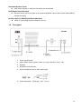
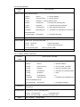
1-4
12kHz IF (I/Q) analog output for DRM PC receiver
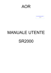
Front panel
1.
Power On/Off switch
2.
Status LED indicator (Green: Power on, orange: Stand by, not lit : Off)
3.
Speaker
4.
SD/SDHC card connector
5.
Stereo headphone jack (3.5mm stereo type)
6.
Video Output jack
(RCA type : 75Ω, 1V p-p)
12
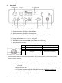
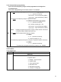
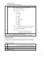
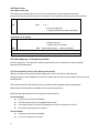
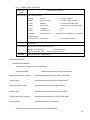
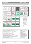
1-5
Rear panel
1. Antenna connector 1 (N type) for above 25MHz
2. Antenna connector 2 (N type) for all frequencies
3. External 10MHz reference signal input connector (SMA type) (2dBm +/- 2dB)
4. Cable clamp
5. Power input connector (10.7~16V DC, 2A @ 12V)
6. 45.05MHz IF output connector (BNC type) (25MHz to 3.15GHz only)
7. ACC (Accessory) connector
Pin #
Description
Pin #
Description
1
12V DC output (30mA max.)
5
Control 2
2
Detector output
6
GPS 1 second input
3
Audio input
7
Audio output (2.5mV/600Ω)
4
Control 1
8
Ground
When a GPS receiver is connected, the internal reference oscillator (10MHz) will be locked by the GPS receiver, and
the highest stability reference signal (0.01ppm) will be obtained. This is ideal for frequency coherent operation and DF
(Direction Finding) applications.
8.
External speaker output connector (3.5mm monaural)
9.
Line output connector (3.5mm stereo, -10dBm/600Ω). Can be selected as 12kHz
I/Q output
10. N/A (for future use)
11. I/Q output connector (Optional, USB type B connector) (25MHz to 3.15GHz only)
12. AUX (Auxiliary connector) Interface for an optional LAN interface
13. USB connector (USB type B connector)
13
2.
PC CONTROL
2-1 System requirements
Hardware:
PC with 2GHz Dual Core CPU, 1GB RAM
USB Port (USB 2.0)
16 bit AC-97 compatible audio board
1024 x 768 (minimum) resolution video board and monitor
2 button mouse with wheel
CD-ROM drive
Operating System:
Windows® 2000 SP4, XP SP2 (32 bit version), Vista or Windows 7.
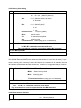
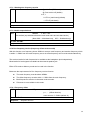
2-2 USB (Universal Interface Bus)
The USB (type B) connector is designed to connect directly to the USB port of a PC.
All functions of the AR2300 can be controlled by a PC by means of the USB interface using either
the supplied AOR control software, or a terminal software.
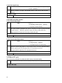
2-2-1 USB driver installation
To control AR2300 with a PC, the USB driver for the AR2300 needs to be installed.
For your convenience, the USB driver is included on the supplied CD program disk.
To avoid any driver conflict, please UNINSTALL ANY OLDER VERSION OF THE VCP DRIVER.
To check if you have such a driver already in your system, go to START > CONTROL PANEL > ADD
OR REMOVE PROGRAMS > search for “Windows driver package – FTDI CDM Driver Package”
If you wish to obtain the latest version of the driver, you can download from the manufacturer’s
website.
http://www.ftdichip.com/ftdrivers.htm
Click “VCP Drivers”, then select the device name “FT232B”.
1. Place the supplied driver CD into your CD drive.
2. Plug the supplied AC adapter into the DC power input connector of the AR2300. Connect the AC
adapter to an electrical outlet and then turn on the power switch.
3. Plug the square end of the USB cable (supplied) into the USB connector on the rear panel of the
AR2300.
4. Plug the other end of the USB cable into an available USB port on the PC.
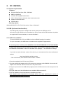
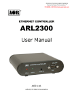
5. The new hardware is found and starts the installation procedure.
Note: Sample screen instructions or messages shown may differ depending the version of
Windows® operating system of your PC.
14
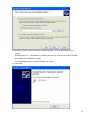
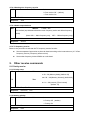
6. Check the “No, not this time” and click “Next”.
7. Check the “Install from a list or specific location [Advanced]” and click “Next”.
15
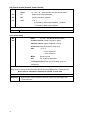
8. Check the “Search for the best driver in these locations.”, “Include this location in the
search:”.
Select the path “D:\USB DRIVER” (or change the letter “D” with the one of the CD-ROM
drive where the CD-ROM is located.)
If you download the driver, select the folder you copied.
9. Click “Next”.
16
10. When the installation is completed, click “Finish”.
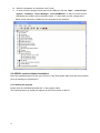
11. In order to find the assigned serial port for the USB port, click the “Start”, “Control Panel”,
“System”, “Hardware”, “Device Manager”, “Ports (COM&LPT)” on the PC monitor screen..
USB Serial port (COM x) will be indicated. (Note: “x” varies from your PC configuration.)
Below screen shows the COM8 has been assigned for the USB port.
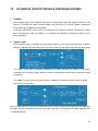
2-3 AR2300 control software installation
Place the supplied program CD into your CD drive. Copy the program folder from CD to any location
(such as desktop) on the hard drive.
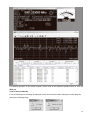
2-3-1 Starting the program
Double click the “AR2300ControlSoft.exe” in the program folder.
The following screen (or similar) will appear on the monitor screen of the PC.
17
For detailed operation of the control program, please refer to the separate operation sheet or click the
HELP tab.
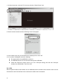
2-3-2 In case of difficulty
If one of following error message is displayed on the monitor screen while starting the control program,
perform the following steps:
18
1. On the main screen, click the “File” tab, then click the “Select Device” tab.
2. Wait for several seconds until the following screen is displayed.
3. If the number (may vary) in the Detect box is displayed, then click “OK”.
4. If no number is displayed, check the following:
The power switch of the AR2300 is turned on.
The AR2300 and the PC are connected through the USB cable.
Check the COM port number (refer to 2-3-1 #11 COM port setting) and enter the COM port
number in the Detect Box. Then click “OK”.
2-4 LAN
With an optional USB to LAN interface unit, the AR2300 can be controlled via the internet. All the control
commands for the LAN interface are the same as the USB control commands.
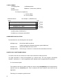
19
3. Control commands (for terminal software)
The following are the specifications for the communication protocol used:
Communication speed: 115,200bps (default), 57,600bps, 38,400bps, 19,200bps, 9,600bps
Data: 8 bit
Stop bit: 1
Parity: None
Flow control: None or RTS/CTS
Echo: Off
Return Code: (PC AR2300): <CR><0x0d>
<LF> ignore
Return Code: (AR2300 PC): <CR><LF>(0x0d, 0x0a)
3-1 Command format
<command><CR>
<command><parameter><CR>
<command><parameter 1><SP><parameter 2><SP><parameter 3><CR>
Each command is completed with a <CR>(0x0d).
3-2 Response format
Although there is no local echo, a specified response should come back from the AR2300 after
confirming the correct command.
If an invalid command is sent to the AR2300, ? <CR><LF> (0x3f, 0x0d, 0x0a) will be returned
as an unrecognized command.
<SP><CR><LF> (0x20, 0x0d, 0x0a) to a valid command (without parameter).
<command><value><CR><LF> to a valid command (with parameter.)
20
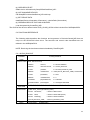
3-3 Power on the AR2300
3-3-1 Wake up
Power on
ZP
Wake up from stand-by mode (QP command) or
sleep mode (SP command).
ZPnn: 00 ~ 99, wake up ID
Note: The power switch must be in the ON position.
3-3-2 Wake up ID set up
Set up wake up ID
ZI
ZInn: 00 ~ 99 (default: 00)
To read: ZI <CR>
Response: ZInn
3-4 Power off the AR2300
3-4-1 Standby mode
QP
Switches the AR2300 to
The front power switch must remain in the ON
standby mode
position.
3-4-2 Sleep timer
SP
Sleep Timer
SPnn:00 ~ 99 (unit: minute)
TR
Sleep Timer Display
TR0: display off
(Displays remaining
TR1: display on (default)
(default: 00 : Off)
time)
3-5 Audio gain
AG
AGnnn
(nnn: 000 –255)
(default: 00)
To read: AG <CR>
Response:
AG nnn
3-6 Frequency/memory channel up/down
ZK
ZK
Change upward
ZJ
ZJ
Change downward
3-7 Step frequency
ST
STnnn.nnn (entry in kHz format)
To read: ST <CR>
Response:
21
STnnn.nnn (kHz)
Default: 100.000 (kHz)
3-8 Receive modes, IF bandwidth, AUTO mode
3-8-1 Command description
MD --- Receive mode setting
(default: 21)
IF ---- IF bandwidth setting
(default: 07)
AU --- Auto mode setting
(default: 1)
AZ --- Destination setting
(default: 0)
(Note: Some functions below 25MHz are not available due to its configuration.)
3-8-2 Simple mode
Command
Description
Mode
IF bandwidth
Remarks
(Hz)
MD21
WFM1
FM
100K
N/A below 25MHz
MD22
WFM2
FM
200K
N/A below 25MHz
MD23
FMST
FM Stereo
200K
N/A below 25MHz
MD24
NFM
FM
15K
N/A below 25MHz
MD25
SFM
FM
6K
N/A below 25MHz
MD26
WAM
AM
15K
MD27
AM
AM
6K
MD28
NAM
AM
3K
MD29
SAM
Synchronous AM
6K
MD30
USB
USB
3K
MD31
LSB
LSB
3K
MD32
CW1
CW
500
MD33
CW2
CW
200
MD34
ISB
ISB
6K
N/A below 25MHz
MD35
AIQ
AIQ
15K
AF-IQ output
AU0
-
-
AUTO mode off
AU1
-
-
AUTO mode on
3-8-3 Advanced mode
Command
Description
Mode
IF bandwidth
Remarks
(Hz)
MD00
FM
FM
N/A below 25MHz
MD01
FMST
FM Stereo
N/A below 25MHz
MD02
AM
AM
MD03
SAM
Synchronous AM
MD04
USB
USB
MD05
LSB
LSB
MD06
CW
CW
22
MD07
ISB
ISB
N/A below 25MHz
MD08
AIQ
AIQ
AF-IQ output
AU0
-
-
AUTO mode off
AU1
AUTO
AUTO
AUTO mode on
IF00
200
200
N/A below 25MHz
IF01
500
500
N/A below 25MHz
IF02
1K
1K
N/A below 25MHz
IF03
3K
3K
IF04
6K
6K
IF05
15K
15K
IF06
30K
30K
IF07
100K
100K
N/A below 25MHz
IF08
200K
200K
N/A below 25MHz
3-8-4 Auto mode
The following parameters are automatically set in the AUTO mode:
Step frequency
Step frequency adjust
Receive mode
IF bandwidth
Offset frequency (for dual frequency receive)
3-8-5 Destination setting
AZ0 --- U.S.A.
AZ1 --- Japan
AZ2 --- Europe
The frequency band plan and receive mode are properly set according to its destination.
3-9 Decode assist function
3-9-1 Auto notch (notch)
The auto notch function is effective to suppress cyclic noise.
LS
LSn
n: 0 ~ 3
0: Off (default)
1: Low
2: Medium
3: High
To read: LS <CR>
Response:
23
LSn
3-9-2 Noise reduction (NR)
The noise reduction function is effective to suppress random noise.
NR
NRn
n: 0, 1
0: Off (default: 0)
1: On
To read: NR <CR>
Response:
NRn
3-9-3 Noise blanker (NB)
The noise blanker function is effective to suppress pulse noise.
NB
NBn
n: 0 , 1
0: Off (default)
1: On
To read: NB <CR>
Response:
NBn
3-9-4 Voice inversion descrambler (VI)
*** NOTE: This function is not available for the US consumer version.***
Available in FM mode.
SC
SCnnn
n: 0 , 200 ~ 700 (2000Hz ~ 7000Hz)
incremental 5 (50Hz)
0: Off (default)
To read: SC <CR>
Response:
SCnnn
3-9-5 IF shift
Not available in FM mode.
IS
ISxnnn
X: +, - (shift direction)
n: -120 ~ +120
(-1200Hz ~ +1200Hz)
Incremental 5 (50Hz)
n: +0 Off (default)
To read: IS <CR>
Response:
ISxnnn
24
3-9-6 CW pitch frequency
Available in CW mode only.
CP
nn: 30 ~ 90 (300Hz ~ 900Hz)
CPnn
Incremental 5 (50Hz)
(default: 80)
To read: CP<CR>
CPnn
Response:
3-9-7 Automatic gain control (AGC)
Not available in FM mode.
AC
n: 0 ~ 3
ACn
n=0
AGC - FAST
n=1
AGC – MEDIUM
n=2
AGC – SLOW
n=3
AGC – MANUAL
(default)
To read: AC <CR>
Response:
Can
3-9-8 Automatic frequency control (AFC)
1) AFC does only work in NFM mode with a filter setting up to 30kHz.
2) It does NOT automatically retune the receiver to the nearest strong signal.
AF
AF
n: 0, 1
3) Real function of AFC: It tunes the IF filter's frequency automatically when an unstable
n
0: Off (default)
frequency is received. It does not change the receive frequency. Since only IF is changed,
1: On
there is no "visual" change on the control program's spectrum or frequency display. The
To read: AF<CR>
Response:
change can only be heard on "audio".
AFn
4) It only works if the sending station's frequency shifts are within the selected IF filter's
bandwidth. Example: IF=15kHz >> +/-7kHz, IF=30kHz >> +/-15kHz
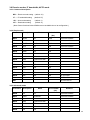
3-9-9 Tone squelch (CTCSS)
CN
nn: 00 ~ 52
CNnn
00: Off (default)
Below is a chart of the CTCS frequency.
n0
n1
n2
n3
n4
n5
n6
n7
n8
N9
0n
-
60.0
67.0
69.3
71.9
74.4
77.0
79.7
82.5
85.4
1n
88.5
91.5
94.8
97.4
100.0
103.5
107.2
110.9
114.8
118.8
2n
120.0
123.0
127.3
131.8
136.5
141.3
146.2
151.4
156.7
159.8
3n
162.2
165.5
167.9
171.3
173.8
177.3
179.9
183.5
186.2
189.9
4n
192.8
196.6
199.5
203.5
209.5
210.7
218.1
225.7
229.1
233.6
5n
241.8
250.3
254.1
-
-
-
-
-
-
-
(Example)
nn: 13 97.4Hz
To read: CN <CR>
Response:
: CNnn
Note: When the AR2300 is detecting a CTCSS tone, it will display the frequency.
25
If the decoded tone frequency is the same as the set frequency, the AR2300
will display its frequency followed by an asterisk (*).
(Example) CN15 103.5* The set CTCSS frequency matches the decoded tone frequency.
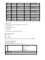
3-9-10 Digital code squelch (DCS)
DS
nnn: see below chart
DSnnn
000: Off (default)
Below is a chart of the DCS codes.
017
023
025
026
031
032
036
043
047
050
051
053
054
065
071
072
073
074
114
115
116
122
125
131
132
134
143
145
152
155
156
162
165
172
174
205
212
223
225
226
243
244
245
246
251
252
255
261
263
265
266
271
274
306
311
315
325
331
332
343
346
351
356
364
365
371
411
412
413
423
431
432
445
446
452
454
455
462
464
465
466
503
506
516
523
526
532
546
565
606
612
624
627
631
632
654
662
664
703
712
723
731
732
734
743
754
-
-
-
-
To read: DS <CR>
Response:
: DSnnn
Note:When the AR2300 is detecting a DCS code, it will display the code.
If the decoded code is the same as the set code, the AR2300 will display
its code followed by an asterisk (*).
(Example) DS131 131* The set DCS code matches the decoded DCS code.
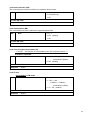
3-9-11 DTMF code
DT
n: 0, 1
DTn
0: Off (default)
1: On
DX
DX
Displays decoded tones
DX%
Clear displayed decode tones
To read: DT<CR>
Response: DTn
or DX<CR>
or
DX cccc………
3-9-12 De-emphasis
EN
ENn
(n: 0, 1)
0: 50uS
(default)
1: 75uS
To read: EN <CR>
Response:
ENn
26
3-10 Squelch
3-10-1 Level squelch
LQ
LQnnn
nnn: 000 ~ 255
(default: 000)
HQ
HQnnn mmm
nnn:000 ~ 255 (for receive frequency above 25MHz)
(default: 000)
mmm: 000 ~ 255 (for receive frequency below 25MHz)
(default: 000)
To read: LQ <CR> or HQ<CR>
Response:
LQnnn
or
HQnnn mmm
3-10-2 Voice squelch
VQ
VQn
n: 0, 1
VT
VTnnn
nnn:000 ~ 255 Delay time (default: 008)
VL
VLnn
nn: 0 ~ 7 Squelch level
To read: VQ <CR>
Response:
0: Off (default)
1: On
(default: 3)
or VT<CR> or VL<CR>
VQn
or
VTnnn or
VLnn
3-11 RF amplifier, attenuator
AT
ATn
n: 0 ~ 4
(default: 0)
n=0
RF AMP = On, Attenuator = 0 dB, Auto attenuator = Off
n=1
RF AMP = Off, Attenuator = 0 dB, Auto attenuator = Off
n=2
RF AMP = Off, Attenuator = -10 dB, Auto attenuator = Off
n=3
RF AMP = Off, Attenuator = -20 dB, Auto attenuator = Off
n=2
Auto attenuator = On
To read: ATy <CR>
Response:
ATmn
m : 0, 1
0: Auto attenuator On
1: Auto attenuator Off
n:0~3
See above
3-12 Antenna select
AN
ANn
n: 0 ~ 2
(default: 1)
n=0
Auto select
n=1
Antenna connector 1
n=2
Antenna connector 2
To read: AN <CR>
Response:
ANmn
m:
Antenna select setting
n:
1, 2
Antenna connector
Note: When the receive frequency is below 25MHz, antenna connector 2 is
automatically selected.
27
3-12-1 Antenna Select programming
Up to 10 receive frequency ranges can be programmed and assigned to
an antenna input.
If the above programming is not made, antenna 1 is selected.
AP
To add new frequency range, use APn xxxx.xxxxxx yyyy.yyyyyy
n: 1, 2 (antenna connector)
xxxx.xxxxxx low end frequency (MHz)
yyyy.yyyyyy high end frequency (MHz)
To assign new frequency range in a specific location,
use APnmm xxxx.xxxxxx yyyy.yyyyyy
n: 1, 2 (antenna connector)
mm: memory location (00 ~ 09)
xxxx.xxxxxx low end frequency (MHz)
yyyy.yyyyyy high end frequency (MHz)
AP% --- Display programmed frequency range for both antenna connectors.
(Frequency below 25MHz cannot be set.)
AD
To delete specific programmed frequency ranges,
use ADnm.
n: 1, 2 (antenna connector)
m: memory location (0 ~ 9)
To delete all programmed frequency ranges on a specific antenna connector,
use ADn%.
n: 1, 2 (antenna connector)
To delete entire programmed memory contents, use
AD%%.
3-13 S-meter
3-13-1 Signal level
LM
Response
To read: LM <CR>
LMnnn.nc
nnn.n: Relative level in dB
c: Squelch status
no display : squelch closed
P: squelch open
V: voice squelch open
A: APCO25 mode
E: APCO25 (encrypted)
D: CTCSS / CTS squelch
28
3-13-2 Auto signal level
LT
LTnnnn
n: 0 or 1 ~ 6000 (in approximately 10 mS)
0: Off
(default)
When n is set to 1 or higher, the AR2300 sends s meter level in above preset
interval.
To read: LT <CR>
Response:
LTnnnn
3-14 Audio recorder control
3-14-1 Control relay status
n: 0 , 1
TPn
TP
0: Off (Relay contact open)
(default)
1: On (relay contact closed)
The relay contact is available at the ACC1 connector to control an external audio
recorder device. When the squelch is open, the relay contact will close.
When squelch is closed, then the relay contact will open.
To read: TP <CR>
Response:
TPn
3-14-2 Control relay status report
TC
TCn
n: 0 , 1
0: Off (No report)
(default)
1: On (Report by the TP command)
When the control relay opens or close during receive, the relay operation status
will be output by the TP command if the TC command is set to on.
No report will be made if the TC command is set to 0.
To read: TC <CR>
Response:
TCn
3-15 Manual RF gain
This command is available only when the AGC is set to 3 (manual mode).
RG
RGnnn
To read: RG <CR>
Response:
29
RG nnn
(nnn: 000 – 110)
(in dB)
(default::110)
3-16 RF filter bandwidth for A/D converter
AB
n: 0 , 1
ABn
0: 10MHz (recommended) (default)
1: 30kHz
This command is used to select the bandwidth of analog filter for the A/D
converter. Normally, it should be set to 10MHz. However, in case of a strong
signal in adjacent frequency, it can be set to 30kHz. This setting does not affect
spectrum display function or FFT search.
To read: AB<CR>
Response:
ABn
3-17 RF band pass filter (for below 25MHz reception)
n: 0 , 1
HNn
HN
0: Off (No filter) (default)
1: On (Filtered)
This command is to select to use or not use a Band Pass Filter (BPF) for 25MHz
signal. This function is available only to receive 25MHz of frequency.
To read: HN <CR>
Response:
4.
HNn
Receive commands
4-1 VFO mode
VF
VFm
m: A ~ E (default: A)
RF
RFnnnn.nnnnnn
nnnn.nnnnnn
(MHz)
Frequency set
(default:0082.500000) (MHz)
The VF command is to select VFO A ~ VFO E.
To set the frequency, use the RF command after selecting the VFO.
The VFO-E is used to set receive frequency below 25MHz in the duo receive
mode.
To read: VF <CR>, RF<CR>
Response:
VFm,
RFnnnn.nnnnnn (MHz)
30
4-2 Search mode (normal search mode)
SS
Start normal search
SSnn
nn : 00 ~ 39 Search in the selected search bank.
ZJ,
ZJ
Search frequency downward
ZK,
ZK
Search frequency upward
LC
LCn
n: 0, 1
SS
0: Frequency data output disabled
(default)
1: Frequency data output enabled
To read: SS<CR>, LC<CR>
Response:
SSnn,
LCn
4-2-1 Search bank
(nn: 00 ~ 39) Search Bank number
SE
SEnn
SR
SLnnnn.nnnnnn (Lower Frequency, MHz)
SUnnnn.nnnnnn (Upper Frequency, MHz)
STnnn.nnn (Search frequency step, kHz)
AUn
(n: 0, 1)
0: Auto mode Off
1: Auto mode On
MDnn
Receive mode
ATn
RF amplifier, attenuator
TTxxxxxxxxxxxx (Enter text as needed, up to 12
characters)
Format:
SEnn SLnnnn.nnnnnn SUnnnn.nnnnnn STnnn.nnn AUn MDnn ATn TTxxxxxxxxxxxx
Note: Refer to individual command for details of each field
To read: SRnn<CR>
Response:
SEnn SLnnnn.nnnnnn SUnnnn.nnnnnn STnnn.nnn AUn MDnn ATn
TTxxxxxxxxxxxx
31
4-2-2 Pass frequency
PW
1. Send PW command while search stops during search mode.
Register a current freq. to the current Pass bank.
2. Send PWnn command while search stops during search mode.
Register a current freq. to the specified (nn) Pass bank.
3. Send PW:mmmm.mmmmmm (MHz) command during search mode.
Register the above frequency to the current Pass bank.
Send PW:mmmm.mmmmmm nnnn.nnnnnn (MHz) command during
search mode.
Register above frequency range to the current Pass bank.
4. Send PWnn mmmm.mmmmmm command in normal receive mode.
Register above frequency to the specified (nn) Pass bank.
5. Send PW%% command while search stops during search mode.
Register a current frequency to all Pass banks.
6. Send PW%% mmmm.mmmmmm (MHz) commandPWnnnnnnnnnnnn in
normal receive mode.
Register above frequency to all Pass banks.
Send PW:mmmm.mmmmmm nnnn.nnnnnn (MHz) command during
search mode.
Register above frequency range to all Pass banks.
After PW command is sent, search function will resume.
PR
Displays a list of pass frequencies
PRnnxx mmmm.mmmmmm (MHz)
(nn: search bank number)
Or,
PRnnxx mmmm.mmmmmm nnnn.nnnnnn (MHz)
(if the pass frequency range is known.)
(xx: the number from the top of the search bank)
PD
PDnnxx
(nn: 00 ~ 39)
(xx: number from the top of the search bank)
Delete search data and pass frequency on designated search bank
PD%%
Delete all search data and pass frequencies on all search banks
32
4-2-3 Normal search setting format
SG
SGnn DLnn FRnn ASn BKxxxxxx…xx
1. SGnn
nn: 00 ~ 19
(Search group number) (00: default)
(Note: The SG00 is not available for search link.)
2. DLnn
nn: 01 ~ 99
(Search delay time, in 0.1 sec.)
(default: 20)
When a signal is lost, it will resume search after the preset delay time.
3. FRnn
nn: 00 ~ 60
(Timer search, in 1 sec.)
(default: 00 Off)
When a signal is received, it will resume search after the preset time.
4. ASn
n: 0, 1
0: Auto store Off (default)
1: Auto store On
When Auto store is set to On, the received frequency will be registered to
Search bank #40.
5. BKxxxxxx…xx
(Example)
Search bank link
To link 02 05 11, then BK020511
To delete search bank link, BK<CR>.
(Note: The DL, FR, AS, and BK commands cannot be used alone independently.
They must always be used in conjunction with the SG command.)
To read: SGnn<CR>
Response:
SGnn DLnn FRnn ASn BKxxxxxx…xx
4-2-4 Search frequency list
FL
There are 1024 channels of search memory in the AR2300. By executing the FL
command, 40 channel data can be displayed.
FLn
n: 0 ~ 4
n: 0 Displays the latest 40 channels (frequencies may duplicate.)
1 Displays the latest 40 channels (frequency not duplicated)
2 Displays 40 channels with the strongest signal
(frequency may duplicate).
3 Displays 40 channels with the strongest signal
(frequency not duplicated.)
4 Displays most frequently detected signals.
FL%
Clear search list
4-3 FFT search
FFT search differs from regular scanning methods (one frequency / step after the other) in that it provides
a spectrum [image] up to 10MHz wide, sampled 15 times per second. Although the search bank basic
settings for normal search and FFT search are done the same way (for Low Frequency, High Frequency,
and text settings), in FFT search the following parameters must also be set.
33
FFT frequency step
Threshold level (signal detection level)
FF
FFnn FSnn FT-nnn
FFnn
Search bank (two digits) select to access.
nn: 00 ~ 39
FSnn
(default: 00)
Frequency step select
nn: 00 ~ 10
00: 5kHz
01: 6.25kHz
02: 8.33kHz
03: 9kHz
04: 10kHz
05: 12.5kHz
06: 20kHz (default)
07: 25kHz
08: 30kHz
09: 50kHz
10: 100kHz
FT-nnn
Set the threshold level. Once set, only signals over
this level will be detected by the FFT search.
-nnn: (dB)
LC
LCn
(default: -80) (dB)
n: 0, 1
0: Disable search result frequency report
1: Enable search result frequency report
(Note: The FS, FT commands cannot be used alone.
They must always be used in conjunction with the FF command.)
4-4 Memory channel
The AR2300 features 2,000 memory channels (50 channels in each of the 40 banks).
The number of memory banks can be reconfigured between 5 ~ 95 (in 5 incremental).
4-4-1 Memory read mode
MR
MRnnmm
nn: 00 ~ 39 (Memory bank)
(default: 00)
mm: 00 ~ 49 (Memory channel)
ZK
ZJ
(default: 00)
Go to next memory channel
Go to previous memory channel
To read: MRnnmm<CR>
34
4-4-2 Memory data setting
MX
MXnnmm GAn MPn MFnnnn.nnnnnn MDnn ATn ANn MTxxxxxxxxxxxx
MXnnmm:
nn: 00 ~ 39 (Memory bank)
mm: 00 ~ 49
(Memory channel)
n: 0, 1 (Memory select, de-select)
GAn:
0: de-select
1: select (default)
n: 0, 1 (Memory pass)
MPn:
0: no
1: yes
MFnnnn.nnnnnn
Frequency (MHz)
MDnn:
receive mode
ATn:
RF attenuator / amplifier
ANn:
Antenna select
MTxxxxxxxxxxxx: Memory tag (up to 12 characters)
Note: Refer to individual command for details of each field.
The MF, MT commands cannot be used alone.
They must always be used in conjunction with the MX command.
To read: MAnnmm<CR>
Response: MFnnnn.nnnnnn MTxxxxxxxxxxxx
4-4-3 Memory bank resizing
The AR2300 features 2,000 memory channels (50 channels in each of the 40 banks). If you
resize a memory which currently contains 50 channels to a new size of 10 channels, the last
40 channels will be deleted and data will be lost. Therefore, it is suggested that you need to
carefully organize your memory data before resizing memory channels.
MW
MWnn MCnn TT xxxxxxxxxxxx
MWnn: Select memory bank
MCnn: Resizing value
nn: 05 ~ 95 (5 incremental)
TT xxxxxxxxxxxx: Memory tag (up to 12 characters)
To read: MWnn<CR>
Response: MWnn MCnn TT xxxxxxxxxxxx
Note: The MC, TT commands cannot be used alone.
They must always be used in conjunction with the MW command.
4-4-4 Delete memory channel
MQ
MQnnmm:
nn: Bank number
mm: Memory channel
35
4-4-5 Delete memory bank
MB
nn: Bank number
MBnn:
4-5 SCAN
4-5-1 Start scan
MS
nn: Memory channel
MSnn
If the memory frequency is registered to pass frequency lit, it will be skipped.
LC
n : 0, 1
LCn:
0: No report (default)
1: Output detected frequency information
4-5-2 Memory data setting
MG
MGnn DLnn FRnn BKxxxxxx…xxxx
The AR2300 features 20 scan groups.
MGnn:
nn: 00 ~ 19 (Scan bank number) (default: 00)
DLnn:
nn: 01 ~ 99 (Squelch delay time) (in 0.1 sec.)
(between squelch closing and scan restart)
(default: 20)
nn: 00 ~ 60 (Free scan) (in 1 second)
FRnn:
(default: 00 Off)
(duration is how long the AR2300 will remain on
active frequency before resuming scan even when the
frequency is still active).
BK
BKxxxxxx….xxxx: Linked bank number
(Example: Link 02 05 11, then BK020511.
(Note: Scan bank 00 cannot be linked.)
To delete bank, enter BK<CR>.
Note: The DL, FR, BK commands cannot be used alone.
They must always be used in conjunction with the MG command.
To read: MGnn<CR>
Response: MGnn DLnn FRnn BKxxxxxx…xxxx
4-5-3 Memory pass
MP
MPn:
n: 0, 1
0: Pass Off
1: Pass
MPnn: nn: 00 ~ 39 (memory bank)
Memory pass cancel on the selected bank
To read: MP<CR>
Response: MPn
36
4-6 Select scan
4-6-1 Start select scan
The Select scan function allows you to scan only a selection of the frequencies that were
previously saved as memory channels. A maximum of 100 channels within a bank can be scanned.
SM
SM
LC
LCn:
(direct command)
n: 0, 1
0: No report (default)
1: Output detected frequency information
4-6-2 Select scan setting
GA
n: 0, 1
GAn:
0: Select scan Off
1: Select scan On (default)
GD
GD
Clear select memory (direct command)
To read: GR<CR>
Response:
GRnnnn
(Displays select scan memory list)
4-7 Duo frequency / tri frequency receive
The Duo frequency / Tri frequency receive functions allow you to monitor two or three separate
frequencies simultaneously.
4-7-1 Duo frequency receive (duo band receive mode)
With this function, one frequency below 25MHz set on the VFO-E (as a sub band) and
another frequency above 25MHz set on the VFO (other than VFO-E, as a main band) can be received
simultaneously.
The received audio for both frequencies are available at the headphone jack independently.
Mixed audio for both signals is available at the external speaker jack.
Below are the requirements for Duo frequency receive function:
(For main band)
Frequency must be above 25MHz.
The FM stereo mode is not available in this mode.
The receiver must be in the VFO mode and it must be set other than VFO-E.
The antenna input must use number 1.
(For sub band)
37
Frequency must be below 25MHz.
The VFO must be set to VFO-E.
4-7-1-1 Starting duo frequency receive
VW
VWnm:
n: @, A ~ D (VFO mode)
@: Duo receive off (default)
m: 0, 1
0: VFO-n (main band) (default)
1: VFO-E (sub band)
To read: VW<CR>
Response:
VWnm
4-7-1-2 Audio output balance
VH
VHnnn:
n: 000 ~ 255
128: default (equal balance between main band audio and sub band audio)
(Note: 000 --- Main band only, 255 --- Sub band only)
To read: VH<CR>
Response:
VHnnn
4-7-2 Duo frequency receive (frequency offset receive mode)
With this function, one frequency above 25MHz is set as a main frequency and another frequency which
is within +/- 5MHz from the main frequency set as an offset frequency can be received simultaneously.
The received audio for both frequencies is available at the headphone jack independently.
Mixed audio for both signals is available at the external speaker jack.
Either VFO mode or Memory mode can be used in the function.
Below are the requirements for Duo frequency receive function:
The main frequency must be above 25MHz.
The offset frequency must be within +/- 5MHz from the main frequency.
Both frequencies must be in the same receive modes.
FM stereo is not available in this mode.
4-7-2-1 Frequency offset
WFpnnnnn.nnnnnn: (MHz)
WF
p: +, -
(Offset direction)
nnnn.nnnnnn: 0 ~ 5MHz (default: 0)
To read: WF<CR>
Response:
WFpnnnn.nnnnnn
38
4-7-2-2 Starting duo frequency receive
WR
WRn:
n: 0, 1
0: Duo receive Off (default)
1: Duo receive On
To read: WR<CR>
Response:
WRn
4-7-2-3 Audio output balance
WV
WVnnn:
n: 000 ~ 255
128: default (equal balance between main frequency audio and offset frequency
audio)
(Note: 000 --- Main frequency only, 255 --- Offset frequency only)
To read: WV<CR>
Response:
WVnnn
4-7-3 Tri frequency receive
Below is the procedure to activate the Tri frequency receive function:
Set two separate frequencies as the main band according to the instructions on (4-7-2 Duo
frequency receive (Frequency offset receive)
5.
Set another frequency below 25MHz as a sub band.
Other receive commands
5-1 Priority receive
5-1-1 Priority setup
PP
PPnnmm
n: 00 ~ 39 (Memory bank) (default: 00)
mm: 00 ~ 49 (Memory channel) (default:00)
TInn
TI
nn: 01 ~ 99 (second) (Time interval)
(default: 10)
To read: PP<CR>, TI<CR>
Response:
PPnnmm, TInn
5-1-2 Starting priority
PO
POn:
n: 0, 1
0: Priority Off (default)
1: Priority On
To read: PO<CR>
Response:
39
POn
5-2 Step adjust
SH
SHnnn.nnn:
nnn.nnn: (kHz)
(default: 000.000)
To read: SH<CR>
Response:
6.
SHnnn.nnn
Spectrum display commands
6-1 Start frequency
TF
TFnnnn.nnnnnn:
nnnn.nnnnnn (MHz)
(default: 0077.500000) (MHz)
To read: TF<CR>
Response:
TFnnnn.nnnnnn
6-2 End frequency
EF
EFnnnn.nnnnnn:
nnnn.nnnnnn (MHz)
(default: 0087.500000) (MHz)
To read: EF<CR>
Response:
EFnnnn.nnnnnn
6-3 Center frequency
CF
CFnnnn.nnnnnn:
nnnn.nnnnnn (MHz)
(default: 0082.500000) (MHz)
To read: CF<CR>
Response:
CFnnnn.nnnnnn
6-4 Span frequency
FP
FPnnnn.nnnnnn:
nnnn.nnnnnn (MHz)
(default: 0010.000000) (MHz)
To read: FP<CR>
Response:
FPnnnn.nnnnnn
6-5 Spectrum step frequency
FE
FEnnn.nnn:
nnn.nnn (kHz)
(default: 062.500) (kHz)
The value is equal to 1/160 of the frequency span.
To read: FE<CR>
Response:
FEnnn.nnn
40
6-6 Marker frequency
6-6-1 Marker frequency setup
KF
KFnnnn.nnnnnn:
nnnn.nnnmmm (MHz)
(default: 0082.500000) (MHz)
The entered value may be changed according to the frequency span and
frequency range.
To read: KF<CR>
Response:
KFnnnn.nnnnnn –mmm
-mmm: signal level (in dB)
6-6-2 Marker frequency/ level auto output
KC
n: 0, 1
KCn
0: Disable data output (default)
1: Enable data output
To read: KC<CR>
Response:
MKnnnn.nnnnnn –mmm
-mmm: signal level (in dB)
6-6-3 Transfer the marker frequency to receive frequency
KG
KG
(Direct command)
6-7 Spectrum data output
Output the level data of each frequency on the screen.
GL
GL<CR><LF>/<SP><CR><LF>
(Note: The separator (/<CR><LF>) has 160 lines.
To read: GL<CR>
Response:
GL<CR><LF>/<SP><CR><LF>
6-8 High speed spectrum data output
Output the level data of each frequency on the screen in high speed.
FD
Convert the signal strength data of one horizontal dot into 1 byte character. Then
repeat this step for a total of 160 characters and output these data followed by
the OK response (<SP><CR><LF>).
To convert the output data to a signal strength level, subtract 0x20 (in
hexadecimal), then add -100dB.
FD<SP><CR><LF>
To read: FD<CR>
Response:
41
FD<SP><CR><LF>
7.
Video Monitor commands
7-1 Activate the video monitor function
VS
VSn
n: 0, 1
0: Deactivate video monitor function
(default)
1: Activate video monitor function
(Note: Video output signal is only available at the video output connector
on the front panel.)
To read: VS<CR>
Response:
VSn
7-2 Frequency shift reverse
VD
Some video transmitters utilize reversed frequency shift modulation in order to
scramble the signal.
VDn
n: 0, 1
0: Normal shift (default)
1: Reverse shift direction
To read: VD<CR>
Response:
8.
VDn
I/Q output commands
When an optional Digital I/Q output unit is installed, USB 2.0 compatible I/Q data output is available.
25MHz to 3.15GHz only
The separate AOR IQ driver must be installed before using this function.
8-1 I/Q bandwidth
In order to use the I/Q output function, you must have an operating system that is compatible with
Isochronous mode and USB 2.0 format.
(Note: A Windows® XP compatible PC is required to use I/Q function.)
IQ
IQn
n: 0, 1
0: 300kHz (default)
1: 1MHz
To read: IQ<CR>
Response:
IQn
42
9.
Data editor commands
DE
DEnn xxxx yyyy
nn: Process number (see below)
xxxx: Channel origin (see below)
yyyy: Channel destination (see below)
nn
Process
00
Transfer contents of memory bank xx to memory bank yy.
02
Copy contents of memory bank xx to memory bank yy.
04
Transfer contents of search bank xx to search bank yy.
06
Copy contents of search bank xx to search bank yy.
08
Transfer contents of memory channel xxxx to memory channel yyyy.
10
Copy contents of memory channel xxxx to memory channel yyyy.
12
Transfer contents of scan group xx to scan group yy.
14
Copy contents of scan group xx to scan group yy.
16
Transfer contents of search group xx to search group yy.
18
Copy contents of search group xx to search group yy.
21
Delete contents of memory bank xx.
22
Delete contents of search bank xx.
23
Delete contents of memory channel xxxx.
(24)
Cancel Pass setting of all channels on memory bank xx.
(Note: Recommend use of MPnn command. Refer to 4-5-3 section of
this manual)
(25)
Cancel Pass setting of all channels on search bank xx.
(Note: Recommended use of PDnn%% command. Refer to 4-2-3
section of this manual.)
43
26
Delete all contents of memory banks.
27
Delete all contents of search banks.
10.
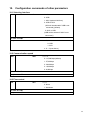
Configuration commands of other parameters
10-1 Selecting interface
CL
CLn
n: 0 ~ 3
0: USB
1: AUX (optional LAN box)
2: USB or AUX
(AUX will be selected if USB is not
connected) (default)
3: AUX or USB
(USB will be selected if AUX is not
connected.)
To read: CL<CR>
Response:
CLmn
m: 0, 1
0: USB
1: AUX
n: 0 ~ 3 (see above)
10-2 Communication speed
SB
SBn
n: 0 ~ 4
0: 115,200 bps (default)
1: 57,600 bps
2: 38,400 bps
3: 19,200 bps
4: 9,600 bps
To read: SB<CR>
Response:
SBn
10-3 Flow control
SF
SFn
n: 0, 1
0: None
1: Hardware
To read: SF<CR>
Response:
SFn
44
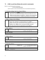
11.
LAN (Local Area Network) control commands
Below is a command format for LAN control:
IP sub command parameter
(Note: No space must be inserted between the sub command and parameter.)
11-1 Readout settings from the optional LAN-box
IP RED
IP RED
(Note: Each sub command will display all its stored data value on the
AR2300 until data readout is completed. Therefore, it is recommended
to use this command before changing /displaying the LAN settings. )
11-2 Write settings to the LAN-box
IP WRT
IP WRT
(Note: This command is to write parameters to the LANBox.
Beware that using this command will write all parameters stored on the
AR2300 to the LANBox before executing the IP RED command.
This may result in the loss of parameters on the LANBox.)
11-3 IPv4 address
IP IPF
IP IPFx.x.x.x
x: 0 ~ 255 (IP address)
(default: 192.168.0.234)
To read: IP IPF<CR>
Response:
IP IPFx.x.x.x
11-4 Mask address
IP
IP MSKx.x.x.x
x: 0 ~ 255 (Mask address)
(default: 255.255.255.0)
MSK
To read: IP MSK<CR>
Response:
IP MSKx.x.x.x
11-5 Gateway address
IP GAT
IP GATx.x.x.x
x: 0 ~ 255 (Gateway address)
(default: 192.168.0.1)
To read: IP GAT<CR>
Response:
45
IP GATx.x.x.x
11-6 DHCP client function
IP
n: 0, 1
IP DHCn
0: Disable (default)
DHC
1: Enable
To read: IP DHC<CR>
Response:
IP DHCn
11-7 Ping response
IP PIN
n: 0, 1
IP PINn
0: Disable
1: Enable (default)
To read: IP PIN<CR>
Response:
IP PINn
11-8 TCP port number
nnnnn: 10000 ~ 65535
IP TCPnnnnn
IP TCP
(default: 50002)
To read: IP TCP<CR>
Response:
IP TCPnnnnn
11-9 UDP port number
IP UDP
nnnnn: 10000 ~ 65535
IP UDPnnnnn
(default: 10002)
To read: IP UDP<CR>
Response:
IP UDPnnnnn
11-10 MAC address
IP MAC
IP MAC
(Read only)
(default: 0.0.0.0.0.0)
To read: IP MAC<CR>
Response:
IP MACx.x.x.x.x.x.x
11-11 Username
IP USR
IP USRcccccccc
cccccccc:username
(up to 8 characters including numbers, underscores)
(default: username)
To read: IP USR<CR>
Response:
IP USRcccccccc
46
11-12 Password
IP PAS
IP PASccccccccccccccc
ccccccccccccccc: Password
(6 ~ 15 characters including ! # $ % & - = ^ : @ + * ? _)
(default: password)
(Note: Password MUST be set.)
To read: IP PAS<CR>
Response:
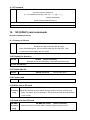
12.
IP PASccccccccccccccc
SD (SDHC) card commands
SD sub command parameter
12-1 Property of SD card
SD INF
SD INF
(Direct command)
Displays the card’s total size and its usage.
Note: After deleting files, remove the SD card from the slot once. Then
re-insert the card to display the free space.
12-2 Display file directory
SD DIR
SD DIR
(Direct command)
Displays the card’s file directory, recorded time and file size.
To read: SD DIR<CR>
12-3 Delete data file
SD DEL
SD DEL xxxxxxxx
xxxxxxxx:file name
12-4 Format card
Format the card
SD FMT
12-5 Write data to SD card
SD MMW
SD MMW (file name)
(Direct command)
(for debug Saves the receivers current state & settings (internal memory content only)
only)
(Note: File name: up to 8 characters. The file extension will be automatically
set to .mmd).
12-6 Read data from SD card
SD MMR
(for debug
only)
47
SD MMR (file name)
(Direct command)
Loads a receivers’s current state & settings (internal memory only)
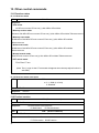
12-7 Squelch skip
SD RSQ
SD RSQ n
n:0, 1
0: recording audio even while squelch is closed.
1: recording audio only while squelch is open.
(default:: 0)
To read: SD RSQ<CR>
Response:
SD RSQ n
12-8 Start/stop recording
SD REC
SD REC (file name)
(Direct command)
Execute the command to start/stop recording audio onto the designated file.
(Note: 1. File name: up to 8 characters. English letters (capital) and some
selected characters can be used as a file name. The file extension
will be automatically set to .wav. If the file name already exists, it will
be automatically overwritten.
2. To stop recording, use the “/” as a file name.
3. If the file size exceeds 2GB, it will stop recording.
12-9 Start/stop playback
SD PLY
SD PLY (file name)
(Direct command)
Execute the command to start/stop playback audio from the designated file.
(Note: 1. File name: up to 8 characters. English letters (capital) and some
selected characters can be used as a file name. The file extension
will be automatically set to .wav.
2. To stop playback, use the “/” as a file name.
Note: Following characters cannot be used as a file name:
¥ /
, ; :
* ? " < >
| .
12-10 Recording status
SD PST
SD PST
(Commands can be sent even during playback or recording)
Response::
0: stand-by mode
1: recording audio even while squelch is closed.
2: Playback mode
3. recording audio while squelch is open or stand-by mode.
48
13. Other control commands
13-1 Receiver status
13-1-1 Receiver status
RX
RX<CR>
Response:
In VFO mode:
VX RFnnnn.nnnnnn STnnn.nnn(+) AUn MDnn ATnm ANnn
In Memory receive mode:
MXnnmm GAn MPn RFnnnn.nnnnnn STnnn.nnn(+) AUn MDnn ATnm ANnn TMxxxxxxxxxxxx
In Memory scan mode:
MS MXnnmm GAn MPn RFnnnn.nnnnnn STnnn.nnn(+) AUn MDnn ATnm ANnn
TMxxxxxxxxxxxx
In Select scan mode:
SM MXnnmm GAn MPn RFnnnn.nnnnnn STnnn.nnn(+) AUn MDnn ATnm ANnn
TMxxxxxxxxxxxx
In Normal search mode:
SRnn RFnnnn.nnnnnn STnnn.nnn(+) AUn MDnn ATnm ANnn TMxxxxxxxxxxxx
In FFT search mode:
FFnn FSnn FT-nnn
(Note: The (+) sign for the ST command will appear when the step adjust function is
activated.)
13-1-2 Receiver status auto report
RT
RTnnnn
n: 0, 1~ 6000 (in 10 mS)
0: Disabled
To read: RT<CR>
Response:
RTnnnn
13-2 Product version
VR
VR
(Direct command)
To read: VR<CR>
Response:
Cxxxxxxxxxxxx Dxxxxxxxxxxxx
C: Main board
VRF
D: Decoder board
VRF
(Direct command)
To read: VRF<CR>
Response:
F:xxxxxxxxxxxx D:xxxxxxxxxxxx
F: FPGA version D:DSP version
49
13-3 Reset
RS
Response:
RS (Direct command)
This command reinitializes the system configuration, however, contents of
VFO and/or memory channels will be saved.
RS2
Response:
RS2 (Direct command)
This command reinitializes the system configuration and VFO data,
however, contents of memory channels will be saved.
RS!
Response:
RS! (Direct command)
This command reinitializes the receiver and returns it to factory’s default
settings.
13-4 Flash memory
MM
Response:
MM (Direct command)
Save current settings to flash memory.
50
14.
51
15.
1
I/Q DIGITAL OUTPUT DETAILS FOR DEVELOPPERS
GENERAL
The I/Q digital output of the AR2300 represents the actual signal used after digital processing in the
receiver. The digital I/Q output interface streams I/Q data to the PC through USB2.0 isochronous
mode, with nearly 72Mbps.wide bandwidth.
A Windows XP/VISTA/7 device driver is provided free of charge for software developers, to allow
them to develop their own I/Q software, or to integrate the AR2300 I/Q acquisition feature to their
existing software..
2
SIGNAL FLOW
In the AR2300 circuitry, 45.05MHz of intermediate frequency (IF) is being sampled directly at 36MHz.
No AGC is applied at the preceding stage in order to obtain a digital signal with wider dynamic range.
The output of the ADC is digitally heterodyned to ZERO frequency to obtain an I/Q signal.
Thereafter, the I/Q signal is being filtered to limit the bandwidth and further down sampling for DSP
processing.
The USB2.0 is running at a top speed of approx. 100Mbps in isochroous mode in order to obtain
the continuous signal flow.
The I/Q output utilizes a CIC filter to simplify the circuit. And the signal flows through FIR Low Pass filter
for getting rid of the alias produced by the CIC filter. The signal is processed into 1MHz bandwidth and
1.125Msamples/sec.
52
3. DATA FORMAT
1) Sampling Rate:
1.125Msample/Sec
2) USB:
72Mbit/sec., Isochronous (USB2.0)
3) Data Format:
Fix Point(2’s compliment)
I: = (29..0): 30bits
Q:= (29..0): 30bits
USB data Stream
One Sample = (16bitsWord x4)
MSB
LSB
I-High(29..15)
15bits
1
1st Word
I-Low (14..0)
15bits
0
2nd Word
Q-High(29..15)
15bits
0
3rd Word
Q-Low(14..0)
15bits
0
4th Word
4 )USB Interface: ENDPOINT 6
5) USB driver for Windows XP/VISTA/7
4.USB DRIVER INSTALLATION
To install the driver, the following files are required.
AORAlpha.sys
AR-ALPHA USB Client Driver
It will be copied in the Windows directory system32¥drivers”
AORAlpha.inf
AR-ALPHA USB client driver inf file
AORAlphaDD.h
IoControl type / Structure / Includes the files that defines GUID etc…
5.NOTE FOR PC SOFTWARE DESIGN
To read the I/Q data, the client driver needs to be interfaced for data acquisition.
The data acquisition is easily accomplished by a simple setup. The test program “AR-ALPHA
TestAPP”, written by C++ can be supplied by AOR. (Sample code is supplied with this software.)
5.1 Get the device path
The supplied client driver needs to obtain the device using SetupDiXXX() API functions before
opening driver by CreateFile() API. This is because the driver interface uses GUID for the
application.
Following is an example to get the device.
53
(a) OPEN DEVICE SET
Obtain device information by SetupDiGetClassDevs() API
(b) LIST AVAILABLE DEVICES
Call SetupDiEnumInterfaceDevice() API with loop.
(c) GET DEVICE PATH
detailData (Device Infromation of Structurer) ->devicePath (Set member)
(d) OPENNING DEVICE THAT HAS ACQUIRED
It can be opened by CreateFile() API
The GUID of the driver is defined under GUID_CLASS_ALPHA of the included file of AORAlphaDD.h
5.2 FUNCTIONS REFERENCE
The following table describes the functions and arguments in DeviceIoControl()API that are
unique to the AR-ALPHA client driver. The structure and control code described here are
defined in the AORAlphaDD.h.
NOTE: Receiving the Isochronous data is handled by ReadFile()API.
5.2.1 ALPHA_BULKOUT
CONTROL
ALPHA_BULKOUT
CODE
PROPTO-TYPE
FUNCTION
STRUCTURE
BOOL DeviceIoControl(
HANDLE
hDevice,
// = DEVICE HANDLE
DWORD
dwIoControlCode,
// = ALPHA_BULKOUT
LPVOID
pInBuffer,
// = PALPHA_BULKOUT_PRM
DWORD
nInBufferSize
LPVOID
lpOutBuffer,
// = NULL
DWORD
nOutBufferSize,
// = 0
LPDWORD
lpBytesReturned,
// = POINTER
LPOVERLAPPED
lpOverlapped
// = Overlapped POINTER
);
OUTPUT TO THE END-POINT OF BULK-OUT OF AR-ALPHA
typedef struct _ALPHA_BULKOUT_PRM {
UCHAR
ucEndPoint;
// OUTPUT END^POINT
ULONG
ulSize;
// OUTPUT DATA SIZE (BYTE)
UCHAR
ucaData[1];
// OUTPUT DATA POINTER
} ALPHA_BULKOUT_PRM,
NOTE
// = sizeof(ALPHA_BULKOUT_PRM)-1+DATA SIZE
*PALPHA_BULKOUT_PRM;
Include header : AORAlphaDD.h
54
5.2.2 ALPHA_BULKIN
CONTROL
ALPHA_BULKIN
CODE
PROPTO-TYPE
BOOL DeviceIoControl(
HANDLE
hDevice,
// = DEVICE HANDLE
DWORD
dwIoControlCode,
// = ALPHA_BULKIN
LPVOID
lpInBuffer, // = PALPHA_BULKIN_PRM
DWORD
nInBufferSize,
//=sizeof(ALPHA_BULKIN_PRM)
LPVOID
lpOutBuffer,
// = POINTER FOR INPUT BUFFER
DWORD
nOutBufferSize,
// = INPUT BUFFER SIZE (BYTE)
LPDWORD
lpBytesReturned,
// = POINTER FOR VARIABLES TO RECEIVE
lpOverlapped
// = Overlapped POINTER
TRANSFER BYTE.
LPOVERLAPPED
FUNCTION
STRUCTURER
);
Input data from the end-point of the BULK-IN for AR-ALPHA
typedef struct _ALPHA_BULKIN_PRM
{
UCHAR
ucEndPoint;
// INPUT END-POINT
ULONG
ulSize;
// INPUT DATA SIZE (BYTE)
} ALPHA_BULKIN_PRM,
REMARK
*PALPHA_BULKIN_PRM;
AORAlphaDD.h (INCLUDE HEDAER)
5.2.3 ALPHA_START_CAPTURE
CONTROL
ALPHA_START_CAPTURE
CODE
PROPTO-TYPE
BOOL DeviceIoControl(
HANDLE
hDevice,
// = DEVICE HANDLE
DWORD
dwIoControlCode,
// = ALPHA_START_CAPTURE
LPVOID
lpInBuffer,
// = PALPHA_CAPTURE_PRM
DWORD
nInBufferSize,
// = sizeof(ALPHA_CAPTURE_PRM)
LPVOID
lpOutBuffer,
// = NULL
DWORD
nOutBufferSize,
// =0
LPDWORD
lpBytesReturned,
// = POINTER FOR VARIABLES TO
RECEIVE TRANSFER BYTE.
LPOVERLAPPED
FUNCTION
STRUCTURER
lpOverlapped
typedef struct _ALPHA_CAPTURE_PRM {
UCHAR
ucIsoInEndPoint;
} ALPHA_CAPTURE_PRM,
NOTE
55
// = Overlapped POINTER
);
Start data acquisition from the end-point of ISOCHRONOUS-IN of the
AR-ALPHA.
INCL. HEADER
// DATA END POINT
*PALPHA_CAPTURE_PRM;
AORAlphaDD.h
5.2.4 ALPHA_STOP_CAPTURE
CONTROL
ALPHA_STOP_CAPTURE
CODE
PROTO-TYPE
BOOL DeviceIoControl(
HANDLE
hDevice,
// = DEVICE HANDLE
DWORD
dwIoControlCode,
// = ALPHA_STOP_CAPTURE
LPVOID
lpInBuffer,
// = PALPHA_CAPTURE_PRM
DWORD
nInBufferSize,
// = sizeof(ALPHA_CAPTURE_PRM)
LPVOID
lpOutBuffer,
// = NULL
DWORD
nOutBufferSize,
// =0
LPDWORD
lpBytesReturned,
// = POINTER FOR VARIABLES TO RECEIVE
TRANSFER BYTE.
LPOVERLAPPED
FUNCTION
STRUCTURER
lpOverlapped
typedef struct _ALPHA_CAPTURE_PRM {
UCHAR
ucIsoInEndPoint;
} ALPHA_CAPTURE_PRM,
REMARK
// = Overlapped POINTER
);
Start data acquisition from the end-point of ISOCHRONOUS-IN of the
AR-ALPHA.
// DATA END-POINT
*PALPHA_CAPTURE_PRM;
INCLUDE HEADER AORAlphaDD.h
APPLICATION NOTE
CALLING PROCEDURE
Typical driver calling procedure is as follows:
Opening DRIVER
Get the device handle through CreatFile API.
Starting isochronous reception
DeviceIoControl API(ALPHA_START_CAPTURE)
Capturer Start
Send DeviceIoControl API(ALPHA_BULKOUT)
Acquiring Captured Data
Call ReadFile API to acquire captured data
Capturer End
Send DeviceIoControl API(ALPHA_BULKOUT)
Ending isochronous reception
DeviceIoControl API(ALPHA_STOP_CAPTURE)
Closing Device
CloseHandle() API to close device
NOTE:; Set size above 512x3x1024 to read with ReadFile()
56
Size is defined as kMinReadSize in AORAlphaDD.h
REGISTRY INFORMATION
The registry information for the driver is as follows:
NOTE: Initial values are described in INI file.
REGISTRY PATH:
:¥HKEY_LOCAL_MACHINE¥SYSTEM¥CurrentControlSet¥Services¥ALPHA
Value Type
Default (hex)
DESCRIPTION
Range (hex)
Type
1
Service type is a kernel driver.
Fixed Value
Start
3
This driver will be loaded at the time of PnP.
Fixed Value
ErrorControl
Group
1
Error message will be generated when driver
Fixed Value
encounter the error.
Extended Base
““Extended Base” is a group to load at the time of boot.
Fixed Value
DebugInfo
101
0~ffffffff
57
Debugging control flag for kernel debugger.
16.
RESET
Should the AR2300 appear to behave strangely, normal operation may be easily achieved by resetting
the microprocessor. Two scenarios may be encountered due to power transients etc:
1.
Symptom: No control of the receiver from a PC.
Turn off the power switch on the front panel. Leave it off for
Action:
approximately 30 seconds. Turn the power switch back on again.
Normal operation should be restored but the last used frequency will be lost.
The AR2300 will restore the second-last frequency to display.
2.
Symptom: The PC screen freezes.
Action:
Reboot your PC and run the control program again.
Should AR2300 still behave strangely, (while the receiver is ON) push the internal reset button “S3” which
is accessible through the bottom case as illustrated:
(the case does not need to be opened)
58
17.
FIRMWARE UPGRADE
FIRMWARE VERSION CHECK
Switch AR2300 on, start the AR2300 Control software and go to:
SETTING > OPTION
The firmware version appears at the bottom of the window, as follows:
C2300_Main_XXXX DYYYY
(for example C2300_Main_001G D001D)
Where XXXX is the “Main” (controller-board) firmware version, and YYYY the decoder board firmware
version.
If a firmware newer than the version in your AR2300 is available, proceed as described below.
SOFTWARE & HARDWARE REQUIRMENTS
3.
AOR’s original software “SHBOOT”.
4.
PC running Windows 2000 or XP SP2, or newer, with a vacant serial communication port
(COM port).
5.
Serial cable (female-female). UPDATE DOES NOT WORK THROUGH USB!
6.
2 boot files and 3 firmware files supplied by AOR
Do not perform an update if the firmware version is already the newest available.
HOW TO ACCESS
Power OFF AR2300.
Access the DIP SWITCH area as illustrated. You do not need to open the receiver!
These are the default dip switch positions
59
To update the firmware, DIP switches need to be repositioned. The previous illustration shows the
location of the DIP switches, and their default (factory setting) position.
Only the area labeled S1 needs to be repositioned. Do not touch the other dip switches and button.
LOADING DATA
Start the flash writer program (SHBoot) by double clicking the SHboot icon. The following screen should
be seen.
Each block must be updated one at a time.
Do not perform an update if the firmware version is already the newest available.
Proceed in the following order:
AR2300 is OFF.
①
Set the dip switches properly
②
Power on AR2300
③
Load the BOOT file
④
Load the FIRMWARE
⑤
Click on WRITE START
⑥
Power OFF AR2300 and start again from STEP 1 if you need to update another block.
To load the data, click the button
to choose the appropriate data file as summarized in the
following table.
Between these 2 updates it is necessary to boot the receiver once
during 30 seconds, with the dip switches in their default position!
DATA FILE NAME
UPDATE
BLOCK
Boot
Firmware
DIP SWITCHES
AR2300_CT_init_XXXXXX.mot
MAIN
(controller)
boot_AR2300_Control.mot
BB_CT_01_XXXXXXXXXXX.mot
BOARD
DECODER
boot_AR2300_Decoder.mot
ar2300-dec-XXXX.mot
BOARD
60
When all updates are done, do not forget to set the dip switches into their DEFAULT position.
CHECK IF THE NEW FIRMWARE HAS BEEN CORRECTLY LOADED
Switch AR2300 on, start the AR2300 Control software and go to:
SETTING > OPTION
The firmware version appears at the bottom of the window, as follows:
C2300_Main_XXXX DYYYY
(for example C2300_Main_001G D001D)
Where XXXX is the “Main” (controller-board) firmware version, and YYYY the decoder board firmware
version.
61
18.
OPTIONAL ACCESSORIES
I/Q board & I/Q software
With this optional internal I/Q unit, a full 1 MHz of bandwidth activity (25MHz to 3.15GHz) can be
stored to the hard drive of a computer for later analysis and review, without loss of quality
APCO P-25 board
With this optional internal board, APCO25 digital voice communication
(non-encrypted, conventional mode) may be decoded.
Format popular in North-America for government and public safety
communications.
USB to LAN interface box
With this optional external LAN interface unit, the AR2300 can be controlled via the internet. All the
control commands for the LAN interface are the same as the USB control commands.
GPS receiver
With this optional external GPS unit, the internal reference oscillator of the AR2300 will
be locked with the GPS frequency standard signal and provide a 0.01 ppm of accuracy
for the 10MHz internal master oscillator.
(3rd party product, design might change)
62
ANTENNAS
DA3200 16 element discone
DA753G compact discone
DA5000 commercial grade discone
SA7000 twin element
MA500 mobile whip
LA380/390 high Q active indoor loops
BNC connectors for all models, except: N for DA5000 and SA7000 includes BNC-N and BNC-PL239 adapters
Note: DA753G is sold under the name DS3000A in the U.S
63
19.
LIMITED WARRANTY (USA only)
AOR USA, Inc. (AOR) warrants its receivers as described below:
AOR will repair or exchange equipment as a result of defects in parts or workmanship for a
period of one year from the date of original retail purchase from an authorized AOR dealer.
Exclusions
The following items are not covered by the AOR limited warranty:
1. Products that are damaged through accident, abuse, misuse, neglect, or user
modifications.
2. Problems that arise through failure to follow directions in the owner’s manual.
3. Exposure of the product to adverse or severe weather conditions, including lightening, temperature
extremes or water, including rainfall or immersion.
4. Exposure to toxic materials, biohazards, radioactive materials or other contamination.
5. Repairs attempted by parties other than AOR or its authorized personnel.
6. Damage that results from improper installation, including improper voltage and/or
reversed polarity, or exposure of a receiver to signal levels exceeding specifications.
7. Damage resulting through the use of accessories from manufacturers other than AOR.
8. Equipment that has had serial numbers removed or altered in any way.
9. Damage that occurred as a result of shipment. Claims must be presented to the carrier.
10. AOR is not responsible for any costs arising from installation or reinstallation of the
equipment, nor for any consequential (such as loss of use) damage claims.
Obtaining Warranty Service
1. You are responsible for shipping the product to AOR and any related costs.
2. Warranty claim must be accompanied by a legible copy of the original product purchase
receipt.
3. You must include a description of the problem(s) encountered with the product.
4. You must include your name, a valid ground shipping address (including zip code) and
telephone contact information.
5. AOR will ship the repaired (or replaced) product by ground transport.
Limitations
Any and all implied warranties, including those pertaining to merchantability and utility for a
specific purpose are limited to the duration of this limited warranty.
AOR’s limits on warranty pertain only to the repair or, at its option, replacement of defective
products. AOR shall not be liable for any other damages, including consequential, incidental
or otherwise, arising from any defect.
64
Some states do not allow limitations on how long an implied warranty lasts and may not
allow the exclusion of incidental or consequential damages. As such, the above limitations
may not apply in every case. This warranty gives you specific legal rights and you may have
other rights that apply in your state.
If you have questions about this limited warranty, or the operation of your AOR product, contact AOR at
(310) 787-8615 during normal business hours (9 am ~ 5 pm Pacific Time Zone), or write to AOR, 20655 S.
Western Ave., Suite 112, Torrance, CA 90501. You may also send a fax to AOR at (310) 787-8619.
Additional information is available at the AOR web site: www.aorusa.com
We suggest attaching your purchase receipt to this half of the warranty card and keeping this information
in a secure location.
AOR Model Number __________________________
Serial Number ________________________________
Dealer Name _________________________________
Purchase Date ________________________________
65
Manufacturer:
AOR, LTD.
2-6-4, Misuji, Taito-Ku,
Tokyo, 111-0055, Japan
URL: www.aorja.com
e-mail: [email protected]
US distributor:
AOR USA, INC.
20655 S. Western Ave. Suite 112
Torrance, CA 90501
Phone: 310-787-8615
Fax: 310-787-8619
URL: www.aorusa.com
e-mail: [email protected]
Printed in Japan
66