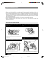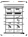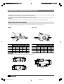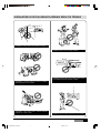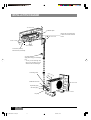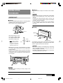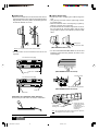
1
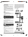
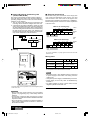
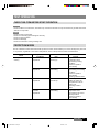
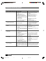
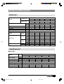
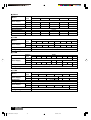
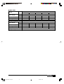
Installation Manual
MINISPLIT
HIGH WALL
AIR CONDITIONER
MODELS
MHC-MHH/BOC-BOH 07
MHC-MHH/BOC-BOH 09
MHC-MHH/BOC-BOH 12
MHC-MHH/BOC-BOH 18
MHC-MHH/BOC-BOH 25
Installation Manual
035T80000-000
01_MHC/BOH 07-25.p65
1
18/3/02, 16:18
CONTENTS
Safety Precautions ...................................... 4
Part List ......................................................... 5
Preparation Before Installation .................. 6
Installation Diagram .................................... 8
Installation Procedure ................................. 9
Test Operation ............................................ 13
Trouble Shooting Guide ............................ 14
Please read this installation manual
carefully before starting the installation.
It will tell you necessary information.
Technical Specification ............................. 15
Quality POLICY
We will continuously strive to satisfy
our customers with consistent reliability
in product, service and support.
2 HIGH WALL
02_MHC/BOH 07-25.p65
2
18/3/02, 16:30
REQUIRED TOOLS
EXTENDED PARTS
1. Refrigerant Pipe
1. Screw driver
2. Hexagonal wrench
MHC-MHH/BOC-BOH
Models
3. Torque wrench
07-09
12
18-25
4. Spanner
Liquid size
1/4 inch
1/4 inch
3/8 inch
5. Reamer
Gas size
3/8 inch
1/2 inch
5/8 inch
2. Pipe Insulation Material (Polyethylene foam
9 mm thick)
6. Hole core drill
7. Tape measure
3. Vinyl tape
8. Thermometer
4. Putty
9. Manifold Guage
10. Gas leak detector
11. Vaccum pump
12. Pipe clamp
13. Pipe Cutter
14. Flare Tool Set
15. Electrical Circuit tester
HIGH WALL
02_MHC/BOH 07-25.p65
3
18/3/02, 16:30
3
SAFETY PRECAUTIONS
• Please read this installation manual carefully before starting installation of the unit.
• This air conditioning system contains refrigerant under pressure, rotating parts and
electrical connection which may be dangerous and can cause injury. Installation
and maintenance of this air conditioning system should only be carried out by trained
and qualified personnel.
• After unpacking, please check the unit carefully for possible damage.
• Before undertaking any work on the unit, make sure that the power supply has
been disconnected.
CAUTIONS FOR INSTALLATION
Do not store or unpack the unit in a wet area or expose
to rain or water.
Do not install in a place where flammable gas may
leak.
It may cause fire.
It may cause the unit to short circuit and may result electric
shocks or fire.
This system is designed for domestic or residential
use only.
Do not conduct installation in wet area or in the rain.
It is a high risk to cause the electrical shocks.
If used in certain envionments, such as a manufacturing
workplace, the equipment may not function efficiently.
4 HIGH WALL
02_MHC/BOH 07-25.p65
4
18/3/02, 16:30
PART LIST
Name of part
Part No.
MHC-MHH/BOC-BOH 07, 09, 12
MHC-MHH/BOC-BOH 18, 25
Quantity
Mounting Plate and Mounting Template
X1
1
Indoor Unit
X1
2
Drain Hose
*Included with indoor unit
X1
3
Central mounting bracket
4
X1
*Not supplied
Screws and Anchor Set
X4
5
Remote Control and Battaries Set
˚C
˚C
˚C
+
—
+
—
TE
—
M
O
D
E
—
C
LE
AR
SE
T
TIM
ER
—
+
M
P
P
M
+
TE
—
M
O
D
E
—
C
LE
AR
SE
T
˚C
TIM
ER
˚C
X1
˚C
—
6
Installation and Owner’s manual
7
Installation
Manual
Owner's Ma
nual
Installation
Manual
Owner's Ma
nual
X1
HIGH WALL
02_MHC/BOH 07-25.p65
5
18/3/02, 16:31
5
PREPARATION BEFORE INSTALLATION
• Before doing any work, check the interior power supply cord and the main breaker capacity are sufficient and the
installation area is sufficient and complies with the requirements.
• Check that the power supply available agrees with nameplate voltage.
• Electrical work, wiring and cables must be performed in compliance with national and local wiring codes and
standard.
• Do not use the extension cables. In the case extended cables are needed, use the terminal block.
SELECTION OF THE LOCATION
• Select a place which provides the space around the units as shown in the diagram below.
Indoor
Outdoor
Models
MHC-MHH/BOC-BOH
09
12
18
07
25
Models
07
MHC-MHH/BOC-BOH
09
12
18
25
A
60cm
60cm
60cm
60cm
60cm
A
20cm
20cm
20cm
20cm
20cm
B
70cm
70cm
70cm
70cm
70cm
B
60cm
60cm
60cm
60cm
60cm
C
60cm
60cm
60cm
60cm
60cm
C
40cm
40cm
40cm
40cm
40cm
10cm
D
20cm
20cm
20cm
20cm
20cm
D
10cm
10cm
10cm
10cm
Cautions
• Do not install in a place that cannot bear the weight of the unit.
133.5
497
133.5
144
517
24
287
100
144
260
316
296
150
100
550
BO 25
BO 18
6 HIGH WALL
02_MHC/BOH 07-25.p65
6
24
BO 07-12
18/3/02, 16:31
150
335
315
234
64
230
268
248
429
64
INSTALLATION IN THE FOLLOWING PLACES MAY RESULT IN TROUBLE
Installation of the indoor unit in direct sun light.
Installation in the unit in wrong direction.
Installation of the indoor unit in a place where there
is an obstacle near the air inlet or outlet.
10 cm
Installation of outdoor units too close or, blowing
discharged air into each other.
Installation of the outdoor unit in a place exposed
regularly to a strong wind.
Installation of the indoor unit at too low a position
HIGH WALL
02_MHC/BOH 07-25.p65
7
18/3/02, 16:31
7
INSTALLATION DIAGRAM
10 cm or more
Installation plate
Remove the cover plate screw
60 cm or more
to have access to the terminal
board.
60 cm or more
70 cm or more
Auto louver (vertical)
Manual louver (horizontal)
Vinyl tape
Apply after carrying out a drainage
test.
* To carry out the drainage test,
remove the air filters and pour
water into the heat exchanger.
Connecting cable
20
cm
or
mo
re
Additional drain hose
20 cm or more
Liquid side piping
Gas side piping
60 cm or more
Vinyl tape
8 HIGH WALL
02_MHC/BOH 07-25.p65
8
18/3/02, 16:31
■ Wiring
INSTALLATION
PROCEDURE
• This indoor unit is ready for connection to the outdoor
unit.
Cautions
INDOOR UNIT
■ Fixing
• Place the installation guide pattern on the designated
installation place and mark the hole position.
• Drill a hole and mount installation plate.
• Never modify the unit by removing any of the safety
guards or by bypassing any of the safety interlock
swithces.
• Connect the interconnecting cable correctly and
connect the connecting cable to terminal as identified
with their respective marking.
• Do not damage the conductor core or inner insulation
of power supply cables and do not deform or crush
the cables.
■ Piping
ø70 mm
A Right
• After determining the pipe
hole position. Drill the hole
at a slight downward slant
towards the outdoor side.
B Right
.. .
... ...
... ..... ..
.. .
... ...... ..
.
.
.
... ...... ..
.. .
... ...... ..
. .
D Right
C Right
Outdoor
F Left
E Rear Bottom
Note : When installing
the refrigerant pipes from
others side. A hole must
be place to allow fall
towards the outdoor unit.
Indoor
.. .
... ...
... ..... ..
.. .
... ...... ..
.
.. .. ......
... ...
... ..... ..
.
... ....
5
The auxiliary piping can be connected in the diections
shown the above diagram. To connect in the D, E and F
direction, pipes will need to be extended.
Cautions
• Make ø5mm. 4-6 holes, in the wall at the four corners
of mouting plate (bracket) then insert appropriate
mouting devices.
• Install the mounting plate using 4-6 pieces of mounting
screw securely at four corners and tighten the screw
completely. Do not over tighten the screws and deform
the back plate.
• Bend pipes carefully to avoid flattening or obstructing
them if the pipes are bent incorrectly, the indoor unit
may be unstable on the wall.
• Carefully arrange pipes so that pipes do not stick out
of the rear plate of the indoor unit.
Caution
• Be careful when handling the sharp edge of the
mounting plate.
HIGH WALL
02_MHC/BOH 07-25.p65
9
18/3/02, 16:31
9
■ Drain hose
■ Indoor Unit Fixing
• Drain hose is flexible and can be routed to suit various
piping arrangements. The drain line must include elbow
trap (U bend). Connect a plastic condensate pipe with
an internal diameter of 12 mm.
• Thread the indoor unit piping and cable through the
hole.
• Hang the top of the unit onto the upper ridge of them
in mounting plate.
• Make sure that the unit is correctly hung in place by
sliding it to the left, then to the right.
• Press the bottom left and bottom right hand corners of
the unit against the mounting plate until the fixing
prongs click into place in the retainers provided to that
effect.
Drainage line
Interconnection cable
Note: Do not put the drain hose end into water.
• The drain hose can be connected to the left or the
right side.
(MHC-MHH/BOC-BOH 07-25)
• For the model MHC-MHH/BOC-BOH 18 and 25 and
install the central mounting bracket as shown in the
below diagram.
For left and left rear piping
Drain hose
(MHC-MHH/BOC-BOH 18 and 25)
Drain cap
Mounting Plate
For left and left rear piping
Central Mounting Bracket
(MHC-MHH/BOC-BOH 18 and 25)
Drain cap
Drain hose
Verification of condensate water drainage:
Fill the drain pan with water and observe evacuation.
a
Condensate
drainage line Vinyl tape
a) Access plate for the
condensate drainage
pump detection
(condensate pump is
available as an
accessory).
Note: The condensate evacuation line should be taped to
the refrigerant lines with vinyl tape.
10 HIGH WALL
03_MHC/BOH 07-25.p65
10
18/3/02, 16:31
OUTDOOR UNIT
■ Fixing and Piping
• Piping must be performed by qualified personnel
according to good refrigeration systems practices.
• Piping materials and insulation materials must be of
refrigerant quality.
• Select the pipe diameters according to the size of unit
and cut the pipe to design length by using pipe cutter.
• Install the flare nuts and flare the end of the pipes.
• Check that no foreign bodies are inside the piping.
• Align the central of the connecting pipes and tighten
the flare nut.
• Fix piping with pipe clamps and check that any pipe
vibrations cannot be transmitted to the building
structure.
- Evacuate the piping. This operation, which should last
at least 15 minutes if there are large piping lengths and
changes in elevation, should be followed by a leak test.
To this effect, when the piping has been evacuated,
close the pressure gauge tap, note the value on the
gauge, then wait for 15 minutes. If the needle moves,
there is a leak in the system. Make the necessary
adjustments or repairs and repeat this procedure until
the needle no longer moves.
- Open the service valves and top up the refrigerant
charge if necessary.
Installation
Notes
• Connect the pipe correctly.
• Do not apply the excessive torque.
• Use an appropriate bending tool to form curves and
avoid over-tightening the refrigerant tubes.
• To prevent heat loss, the two lines must be insulated
separately.
Minimum thickness 6 mm
Heat pump
(discharge)
Heat pump
L
■ Maximum piping lengths
Unit size
D (m)
L (m)
H (m)
7
10
12
7
9
12
15
10
12
15
18
12
Liquid
D
18
15
18
12
25
22
25
20
Cooling
Cooling
(suction)
Heat pump
(discharge)
Note : Where the difference in elevation between the indoor
unit and the outdoor unit is greater than 5 meters,
install an oil trap every 5 meters.
Heat pump
The suction line must have a 2% gradient up to the
compressor on horizontal sections.
Where piping lengths are unusually long and include a
large number of oil traps, it may be necessary to adjust
to compressor charge.
Refrigerant charge to be added per extra
metre of piping length when more than 7.5
meters.
Unit size
g/m
7
15
MHC-MHH/BOC-BOH
9
12
18
15
15
40
L
Liquid
H
GASS
Cooling
(suction)
Low pressure
Cooling
High pressure
Manifold
25
40
■ Refrigerant piping connections
(FLARE connections)
To avoid alteration of unit capacities, check that piping
lengths and changes in elevation are kept to a strict
minimum.
Liquid valve
Outdoor Unit
Before connectiong the refrigerant lines, follow the
procedures below (if pre-charged connection lines are
not supplied):
- Select copper pipe diameters according to the size of
unit to be installed.
- Install the refrigeration lines, checking that no foreign
boodies get inside the piping.
- Install the flare connectors and flare the ends of the
pipes.
Gas valve
Pressure tap
Gas Line
Indoor Unit
Liquid Line
R22
This unit is shipped complete with a charge of R22 refrigerant
that will be sufficient for an interconnecting piping length of
5 meters.
HIGH WALL
03_MHC/BOH 07-25.p65
11
18/3/02, 16:31
11
■ Vertical Discharge Condensing Unit
(H*DA, H*DB, H*RA)
The indoor unit and interconnecting wiring voltage is
220 volts. Where the outdoor unit requires a different
operating voltage such as 24 volts one of the following
solutions can be applied.
1. The coil of the relay switching the compressor and
reversing valves should be changed to a 220V coil.
2. A transformer should be installed to supply 24 volts
and a relay installed with a 220 volt coil to switch the
24 volts required by the outdoor units. The transformer
should be energised at all times and not switched by
the start signal from the indoor unit. Switching the
transformer directly will cause electronic noise which
may cause malfunction of the electronics.
Power Supply
24 V FROM OUTDOOR UNIT
■ Electrical Connections
All electrical wiring and connections must comply with
local codes and standards. Power supply cord and
interconnection cord used must not be lighter than
Polychloroprene sheated cord (245 IEC 57 or H05RN-F).
Disconnecting device must have a contact separation
of at least 3 mm.
MHC 07-25 -Cooling Only
1
N
L
N
3
2
2
1
Indoor
Unit
4
3
4
Outdoor
Unit
Power 220-240V/1Ph/50Hz
Supply 208-230V/1Ph/60Hz
Cooling Only Units
Indoor
Unit
MHC 07-25 -Heat Pump
Indoor
Unit
1
N
L
N
3
2
2
1
Outdoor
Unit
4
3
4
Power 220-240V/1Ph/50Hz
Supply 208-230V/1Ph/60Hz
■ Wiring
For correct installation, a proper ground connection must be
made for unit.
Wiring sizes
Unit size
Power supply
7
mm2
Interconnection Cooling mm2
(Indoor/Outdoor) Heating mm2
Fuse (slow-Blow)
A
9
12
3x2.5
18
25
3x4
3x2.5 + Ground
4x2.5 + Ground
10
16
20
Or as required to meet national and local codes.
Notes
L N 1
2
• Terminals N and 1 (see diagrams above) correspond
to power supply to the indoor unit coming from the
outdoor unit.
• Compressor power supply is established by teminal 2.
• Power supply to the 4-way valve is established by
terminal 3.
• For further details on wiring of these units, see the
diagrams pasted inside each unit.
For further detail on wiring of these units, see the diagrams pasted
inside each unit.
Cautions
• Never modify the unit by removing any of the safety
guards or by bypassing any of the safety interlock
swithces.
• Connect the connecting cable correctly and connect
the connecting cable to terminal as identified with their
respective marks.
• Do not scratch the conductive core & inner insulator of
power supply cables and do not deform or smash on
the surface of cables.
12 HIGH WALL
03_MHC/BOH 07-25.p65
12
18/3/02, 16:31
TEST OPERATION
CHECK THIS ITEM BEFORE START OPERATION
Outdoor
• Check the flare nut connections, valve stem cap connections and service cap connections for gas leak with a leak
detector or soap water.
Indoor
•
•
•
•
•
Check the unit is firmly fixed.
Check the connecting pipes are tighten securely.
Check the pipe insulation.
Check the drainage.
Check the connection of the grounding wire.
PROTECTION MODES
Your air coditioner includes several automatic protection modes, which enables you to use it virtually at any time and
in any season, regardless of the outdoor temperature. Some of the protection modes are listed below:
Operation
conditions
Mode
Cooling
and Dry
Heating
Protection
from
Controlled
remedy
Low outdoor
temperature
Indoor coil
freezing up
Stop outdoor fan and
Compressor when
approaching freezing
conditions.
Resumes operation
automatically.
High outdoor
temperature
Outdoor coil
overheating
Stops compressor when
approaching over heating
conditions.
Resumes operation
automatically.
Operating indicator blinks.
Low outdoor
temperature
Outdoor coil
ice build up
Reverses operation from
heating to cooling for
short periods to de-ice
outdoor coil.
Operating indicator
blinks.
High indoor
or outdoor
temperature
Indoor coil
overheating
Stops outdoor fan and
compressor when
approaching high indoor
coil temperature.
Resumes operation
automatically.
HIGH WALL
03_MHC/BOH 07-25.p65
13
18/3/02, 16:31
13
TROUBLE SHOOTING GUIDE
Probable cause
Problem
A. The air conditioner does not run.
1. Power Failure.
2. Fuse blown or circuit breaker
open.
3. Voltage is too low.
4. Faulty contactor or relay.
5. Electrical connections loose.
6. Thermostat adjustment too low
(in heating mode) or too high (in
cooling mode)
7. Faulty Capacitor
8. Incorrect wiring, terminal loose
9. Pressure switch tripped
B. The outdoor fan runs but the
compressor will not start.
1. Motor winding cut or grounded.
2. Faulty Capacitor.
C. There is insufficient heating or
cooling.
1. There is a gas leak.
2. Liquid and gas line insulated
together.
3. The room was probably very hot
(cool) when you started the
system.
D. The compressor run
continuously.
E. The compressor starts but shuts
down quickly.
1. Wait for Power resume.
2. Replace the fuse or reset the
breaker.
3. Find the cause and fix it.
4. Replace the faulty component.
5. Retighten the connection.
6. Check Thermostat setting.
7. Find the cause then replace
Capacitor.
8. Check and retighten.
9. Find the cause before reset.
1. Check the wiring and the
compressor winding resistance.
2. Find the cause then replace
Capacitor.
1. Remove charge, repair, evacuate
and recharge.
2. Insulate them separately.
3. Wait while unit has enough time to
cool the room.
1. Thermostat adjustment too low
(in heating mode) or too high (in
cooling mode)
2. Faulty fan.
3. Refrigerant charge too low, leak.
4. Air or incondensables in
refrigerant circuit.
1. Check Thermostat setting.
1. Too much or too little refrigerant.
1. Remove charge, evacuate and
recharge.
2. Determine the cause and replace
compressor.
3. Remove charge, evacuate and
recharge.
4. Replace it.
2. Faulty compressor.
F. Clicking sound is heard from
the air conditioner.
Remedy
3. Air or incondensables in
refrigerant circuit.
4. Changeover valve damaged or
blocked open (heat pump unit)
In heating or cooling operation any
plastic parts may expand or shrink
due to a sudden temperature change
in this event, a clicking sound may
occur.
2. Check condenser air circulation.
3. Find leak, repair and recharge.
4. Remove charge, evacuate and
recharge.
In heating or cooling operation any
plastic parts may expand or shrink due
to a sudden temperature change in this
event, a clicking sound may occur.
14 HIGH WALL
03_MHC/BOH 07-25.p65
14
18/3/02, 16:32
TECHNICAL SPECIFICATION
INDOOR UNIT
MHC-MHH
Indoor Unit
07
Models
Outdoor Unit
09
12
18
25
18
25
BOC-BOH
07
09
Ph
1
1
1
1
1
kW
0.7
0.85
1.2
2
2.8
Running Current
A
3.5
4.5
5.6
9.1
11.5
Fuse Size
A
10
10
10
16
20
Power Supply
12
V/Ph/Hz
Maximum Power Consumption
220-240/1/50
System Operation Control
Wireless Remote Control with LCD Display
Compressor
Type
Piping
Diameter
3/8"
3/8"
1/2"
5/8"
5/8"
Liquid
1/4"
1/4"
1/4"
3/8"
3/8"
Indoor
Dimensions
Outdoor
Weights
Rotary
Suction
H(mm)
290
290
290
315
356
W(mm)
799
799
799
1,019
1,019
D(mm)
181
181
181
180
180
H(mm)
492
492
492
590
696
W(mm)
764
764
764
820
850
287
D(mm)
230
230
230
280
Indoor
kg
11
11
11
18
18
Outdoor
kg
34
36
38
59
65
CONDENSING UNIT
■ BOC-BOH
Models
Power Supply
Power Consumption
Outdoor
Unit
BOC-BOH
07
09
12
18
25
220/240/1/50
V/Ph/Hz
Ph
1
1
1
1
1
kW
0.77
0.91
1.21
1.73
2.62
A
3.77
4.42
5.52
8.42
12.82
Running Current
Rotary
Compressor
R-22
Refrigerant Type
Air Flow
3
m /h
1,220
1,220
1,220
3,310
3,310
noise Level
dBa
50
50
51
57
57
HIGH WALL
03_MHC/BOH 07-25.p65
15
18/3/02, 16:32
15
■ R407C
Models
Power Supply
Power Consumption
Running Current
Outdoor
MOL-MOM
07
Unit
09
12
18
25
1
220/240/1/50
V/Ph/Hz
Ph
1
1
1
1
kW
0.77
0.93
1.34
1.77
2.65
A
3.52
4.32
6.12
8.12
12.42
Rotary
Compressor
R-407C
Refrigerant Type
Air Flow
m3/h
1,220
1,220
1,220
3,310
3,832
noise Level
dBa
50
50
51
57
57
■ H*DA
Models
Power Supply
Outdoor
Unit
H*DA
012
024
030
036
048
220-240/1/50
V/Ph/Hz
Ph
018
1
1
060
076
380/3/50
1
1
Compressor
3
3
3
3
Reciprocating
Refrigerant Type
R-22
■ H*DB
Models
Outdoor
Unit
H*DB
012
018
024
030
036
-
Power Supply
Ph
042
048
060
076
208/230-1-60
V/Ph/Hz
1
1
1
1
-
460-3-60
-
1/3
1
460-3-60
1/3
Reciprocating
Compressor
1/3
Scroll
3
Recip
R-22
Refrigerant Type
■ H*RA
Models
Power Supply
Outdoor
Unit
H*RA
018
030
1
1
048
380/3/50
1
1
3
3
3
R-22
Refrigerant Type
208/230-1-60
V/Ph/Hz
Ph
1
1
1
1
Reciprocating
Compressor
16 HIGH WALL
16
1
1
Scroll
R-22
Refrigerant Type
03_MHC/BOH 07-25.p65
060
Reciprocating
Compressor
Power Supply
036
220-240/1/50
V/Ph/Hz
Ph
024
18/3/02, 16:32
■ MMC-MMH
Models
Power Supply
Power Consumption
Outdoor
Unit
MMC-MMH
018
021
025
1
1
1
1
1
kW
2x0.85
0.85x1.20
2x1.20
2x1.73
2x2.26
A
2x4.5
4.5x5.7
2x5.7
16.9
Rotary
Compressor
26.5
Recip
R-22
Refrigerant Type
Power Consumption
050
Ph
Running Current
Power Supply
036
220-240/1/50 or 380-415/3/50
V/Ph/Hz
208-230/1/60
V/Ph/Hz
Ph
1
1
1
1
1
kW
2x0.85
0.85x1.20
2x1.20
2x1.73
2x2.26
A
2x4.5
4.5x5.7
2x5.7
16.9
Running Current
Rotary
Compressor
26.5
Recip
R-22
Refrigerant Type
HIGH WALL
03_MHC/BOH 07-25.p65
17
18/3/02, 16:32
17
––––––––/––––––––––––/––––––––
18 HIGH WALL
03_MHC/BOH 07-25.p65
18
18/3/02, 16:32
––––––––/––––––––––––/––––––––
HIGH WALL
03_MHC/BOH 07-25.p65
19
18/3/02, 16:32
19
DE - COMMISSIONING DISMANTLING & DISPOSAL
This product contains refrigerant under pressure, rotating parts, and electrical connections which may be a
danger and cause injury!
All work must only be carried out by competent persons using suitable protective clothing and safety precautions.
Read the Manual
Risk of electric shock
Unit is remotely controlled and
may start without warning
1. Isolate all sources of electrical supply to the unit including any control system supplies switched by the unit. Ensure
that all points of electrical and gas isolation are secured in the OFF position. The supply cables and gas pipework may
then be disconnected and removed. For points of connection refer to unit installation instructions.
2. Remove all refrigerant from each system of the unit into a suitable container using a refrigerant reclaim or recovery unit.
This refrigerant may then be re-used, if appropriate, or returned to the manufacturer for disposal. Under No
circumstances should refrigerant be vented to atmosphere. Where appropriate, drain the refrigerant oil from each
system into a suitable container and dispose of according to local laws and regulations governing disposal of oily
wastes.
3. Packaged unit can generally be removed in one piece after disconnection as above. Any fixing down bolts should be
removed and then unit lifted from position using the points provided and equipment of adequate lifting capacity.
Reference MUST be made to the unit installation instructions for unit weight and correct methods of lifting. Note that
any residual or spilt refrigerant oil should be mopped up and disposed of as described above.
4. After removal from position the unit parts may be disposed of according to local laws and regulations.
YORK® International Corporation
03_MHC/BOH 07-25.p65
20
18/3/02, 16:32