1
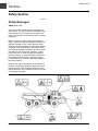
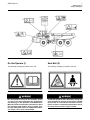
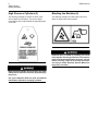
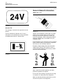
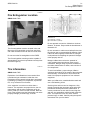
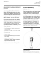
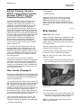
SAFETY
Operation and Maintenance
Manual Excerpt
© 2010 Caterpillar
All Rights Reserved
®
®
SEBU7814-09
October 2009
Operation and
Maintenance
Manual
725 and 730 Articulated Trucks
B1L1-Up (Machine)
B1M1-Up (Machine)
SAFETY.CAT.COM
i03684547
Important Safety Information
Most accidents that involve product operation, maintenance and repair are caused by failure to observe
basic safety rules or precautions. An accident can often be avoided by recognizing potentially hazardous
situations before an accident occurs. A person must be alert to potential hazards. This person should also
have the necessary training, skills and tools to perform these functions properly.
Improper operation, lubrication, maintenance or repair of this product can be dangerous and
could result in injury or death.
Do not operate or perform any lubrication, maintenance or repair on this product, until you have
read and understood the operation, lubrication, maintenance and repair information.
Safety precautions and warnings are provided in this manual and on the product. If these hazard warnings
are not heeded, bodily injury or death could occur to you or to other persons.
The hazards are identified by the “Safety Alert Symbol” and followed by a “Signal Word” such as
“DANGER”, “WARNING” or “CAUTION”. The Safety Alert “WARNING” label is shown below.
The meaning of this safety alert symbol is as follows:
Attention! Become Alert! Your Safety is Involved.
The message that appears under the warning explains the hazard and can be either written or pictorially
presented.
A non-exhaustive list of operations that may cause product damage are identified by “NOTICE” labels
on the product and in this publication.
Caterpillar cannot anticipate every possible circumstance that might involve a potential hazard.
The warnings in this publication and on the product are, therefore, not all inclusive. You must
not use this product in any manner different from that considered by this manual without first
satisfying yourself that you have considered all safety rules and precautions applicable to the
operation of the product in the location of use, including site-specific rules and precautions
applicable to the worksite. If a tool, procedure, work method or operating technique that is not
specifically recommended by Caterpillar is used, you must satisfy yourself that it is safe for you
and for others. You should also ensure that the product will not be damaged or become unsafe by
the operation, lubrication, maintenance or repair procedures that you intend to use.
The information, specifications, and illustrations in this publication are on the basis of information that
was available at the time that the publication was written. The specifications, torques, pressures,
measurements, adjustments, illustrations, and other items can change at any time. These changes can
affect the service that is given to the product. Obtain the complete and most current information before you
start any job. Caterpillar dealers have the most current information available.
When replacement parts are required for this
product Caterpillar recommends using Caterpillar replacement parts or parts with equivalent
specifications including, but not limited to, physical dimensions, type, strength and material.
Failure to heed this warning can lead to premature failures, product damage, personal injury or
death.
In the United States, the maintenance, replacement, or repair of the emission control devices and
systems may be performed by any repair establishment or individual of the owner's choosing.
6
Safety Section
Safety Messages
SEBU7814-09
Safety Section
i02886436
Safety Messages
SMCS Code: 7000
There are several specific warning messages on
this machine. The exact location of the hazards and
the description of the hazards are reviewed in this
section. Please become familiarized with all warning
messages.
Make sure that all of the warning messages are
legible. Clean the warning messages or replace the
warning messages if you cannot read the words.
Clean the warning messages or replace the warning
messages if the illustrations are not legible. When
you clean the warning messages, use a cloth, water
and soap. Do not use solvent, gasoline, or other
harsh chemicals to clean the warning messages.
Solvent, gasoline, or harsh chemicals could loosen
the adhesive that secures the warning message.
Loose adhesive will cause the warning message to
fall off the machine.
Replace any warning message that is damaged, or
missing. If a warning message is attached to a part
that is replaced, install a warning message on the
replacement part. Any Caterpillar dealer can provide
new warning messages.
Illustration 2
g01436938
SEBU7814-09
7
Safety Section
Safety Messages
g01436937
Illustration 3
Do Not Operate (1)
Seat Belt (2)
This warning message is located in the cab.
This warning message is located in the cab.
g01370904
g01370908
Do not operate or work on this machine unless
you have read and understand the instructions
and warnings in the Operation and Maintenance
Manuals. Failure to follow the instructions or heed
the warnings could result in injury or death. Contact any Caterpillar dealer for replacement manuals. Proper care is your responsibility.
A seat belt should be worn at all times during machine operation to prevent serious injury or death
in the event of an accident or machine overturn.
Failure to wear a seat belt during machine operation may result in serious injury or death.
8
Safety Section
Safety Messages
SEBU7814-09
High Pressure Cylinders (3)
Blocking the Machine (4)
This warning message is located on both of the
service brake accumulators. The service brake
accumulators are located behind the right side panel
of the cab.
This warning message is located above the front
wheel on both sides of the machine.
g01430344
g01130902
High pressure cylinder. Do not remove any parts
until pressure has been relieved or personal injury
may occur.
See your Caterpillar dealer for tools and detailed
information required for charging cylinders.
Personal injury or death by crushing can result
from improper servicing procedures. The machine
frame must be blocked and the pressure relieved
before servicing. Failure to do so may cause serious injury or death. Read the Service Manual for
the proper procedure.
SEBU7814-09
9
Safety Section
Safety Messages
High Pressure Cylinder (5)
High Compressed Spring (6)
This warning message is located on the parking
brake accumulator. The parking brake accumulator is
located on the right side of the rear frame.
This warning message is located on the brake
actuator.
g01065910
Personal injury or death can result from a compressed recoil spring being released suddenly using incorrect disassembly procedures.
g01130903
High pressure cylinder. Do not remove any parts
until pressure has been relieved or personal injury
may occur.
See your Caterpillar dealer for tools and detailed
information required for charging cylinders.
A recoil spring that is still held in compression
can result in the recoil spring being released unexpectedly with extreme force which could cause
serious injury or death.
Make sure that the correct disassembly procedure
is used, if a front track roller frame that has a crack
in the parent metal or weld connection (or a tubular section that has separated from the front of
the frame assembly) when the recoil spring is still
held in compression.
Refer to Special Instruction, SMHS8273 which
contains the disassembly procedure that must be
used to decrease the possibility of injury while
performing service on the track roller frame.
10
Safety Section
Safety Messages
SEBU7814-09
No Clearance (7)
Suspension Cylinder Strut (8)
This warning message is located on the fenders on
both sides of the machine.
This warning message is located on the suspension
cylinder struts on both sides of the front of the
machine.
g01371647
g01142855
Connect the steering frame lock between the front
and the rear frames before lifting, transporting, or
servicing the machine in the articulation area. Disconnect the steering frame lock and secure the
steering frame lock before resuming operation.
Severe injury or death could occur.
High Pressure Cylinder.
Do not remove any valve, hydraulic fitting, or
valve core nor disassemble any cylinder parts
until pressure is relieved. Personally injury or
death may occur.
See service manual for correct procedure to relieve pressure and to charge cylinders.
SEBU7814-09
11
Safety Section
Safety Messages
Hot Coolant Under Pressure (9)
Body Prop (11)
This warning message is located behind the operator
compartment.
This warning message is located on both sides of
the rear frame.
g01371640
g01430347
The coolant is hot and the coolant is under pressure. Do not touch the hot surfaces. Refer to the
Operation and Maintenance Manual for the procedure to follow when you check the radiator.
Install dump body prop before working under a
raised dump body to prevent it from falling which
could result in personal injury or death.
No Clearance (10)
Proper Connections for Jump Start
Cables (12)
This warning message is located on the fenders on
both sides of the machine.
This warning message is located on the front side of
the hood on both sides of the machine.
g01053243
Stay back a safe distance. No clearance for a person in this area when the machine turns. Severe
injury or death from crushing could occur.
g01370909
Explosion Hazard! Improper jumper cable connections can cause an explosion resulting in serious
injury or death. Batteries may be located in separate compartments. Refer to the Operation and
Maintenance Manual for the correct jump starting
procedure.
12
Safety Section
Additional Messages
SEBU7814-09
Prop for the Cab (13)
ROPS Certification (15)
This warning message is located on the manual hand
pump for tilting the cab.
This warning message is located on the back of the
cab.
g01430342
Install cab prop pin before working under raised
cab to prevent it from falling which could result in
injury or death.
g01131392
Product Link (14)
If the machine is equipped with Product Link, this
warning message is located in the cab.
Structural damage, an overturn, modification, alteration, or improper repair can impair this structure's protection capability thereby voiding this
certification. Do not weld on or drill holes in the
structure. Consult a Caterpillar dealer to determine this structure's limitations without voiding
its certification.
i02885514
Additional Messages
SMCS Code: 1000; 7000; 7405
g01370917
This machine is equipped with a Caterpillar Product Link communication device which must be deactivated within 12 m (40 ft) of a blast zone. Failure
to do so could result in serious injury or death.
There are several specific messages on these
machines. The exact location of the messages and
the description of the messages are reviewed in
this section. Please become familiarized with all
messages.
Make sure that all of the messages are legible.
Clean the messages or replace the messages if the
words or images are unreadable. When you clean
the messages, use a cloth, water and soap. Do not
use solvent, gasoline, or other harsh chemicals to
clean the messages. Solvents, gasoline, or harsh
chemicals could loosen the adhesive that secures the
messages. Loose adhesive will allow the messages
to fall.
SEBU7814-09
13
Safety Section
Additional Messages
Replace any message that is damaged, or missing.
If a message is attached to a part that is replaced,
install a message on the replacement part. Any
Caterpillar dealer can provide new messages.
Retarding Guidelines
This message is located inside the cab.
Illustration 4
The Product Link System is a satellite communication
device that transmits information regarding the
machine back to Caterpillar and Caterpillar dealers
and customers. All logged events and diagnostic
codes that are available to the Caterpillar Electronic
Technician (ET) on the CAT data link can be sent
to the satellite. Information can also be sent to the
Product Link System. The information is used to
improve Caterpillar products and Caterpillar services.
g01319966
g01418953
Typical example
Illustration 6
Information for Air Conditioner System Service
ELC (Extended Life Coolant) Cooling System
This message is located inside the cab.
This message is located behind the cab near the cap
for the cooling system.
Do not work on the air conditioning system until you
have read the service manual and you understand
the service manual.
This machine is shipped from the factory with ELC.
Illustration 5
Product Link Data Privacy
This message is located in the cab.
g01294295
Illustration 7
g00955999
24 Volt Electrical System
This message is located near the batteries and
the auxiliary start receptacle on the left front of the
machine.
This machine is equipped with a 24 volt electrical
system.
14
Safety Section
General Hazard Information
SEBU7814-09
i03559343
General Hazard Information
SMCS Code: 7000
Illustration 8
g01126478
Alternate Exit
This message is located on the right side rear cab
window.
This film identifies an alternate exit. for more
information on the alternate exit, refer to Operation
and Maintenance Manual, “Alternate Exit”.
Illustration 10
g00104545
Attach a “Do Not Operate” warning tag or a similar
warning tag to the start switch or to the controls
before you service the equipment or before you
repair the equipment. These warning tags (Special
Instruction, SEHS7332) are available from your
Caterpillar dealer.
Know the width of your equipment in order to maintain
proper clearance when you operate the equipment
near fences or near boundary obstacles.
Be aware of high voltage power lines and power
cables that are buried. If the machine comes in
contact with these hazards, serious injury or death
may occur from electrocution.
Illustration 9
g01002993
Illustration 11
g00702020
Wear a hard hat, protective glasses, and other
protective equipment, as required.
Do not wear loose clothing or jewelry that can snag
on controls or on other parts of the equipment.
Make sure that all protective guards and all covers
are secured in place on the equipment.
SEBU7814-09
Keep the equipment free from foreign material.
Remove debris, oil, tools, and other items from the
deck, from walkways, and from steps.
Secure all loose items such as lunch boxes, tools,
and other items that are not a part of the equipment.
Know the appropriate work site hand signals and
the personnel that are authorized to give the hand
signals. Accept hand signals from one person only.
Do not smoke when you service an air conditioner.
Also, do not smoke if refrigerant gas may be present.
Inhaling the fumes that are released from a flame that
contacts air conditioner refrigerant can cause bodily
harm or death. Inhaling gas from air conditioner
refrigerant through a lighted cigarette can cause
bodily harm or death.
Never put maintenance fluids into glass containers.
Drain all liquids into a suitable container.
Obey all local regulations for the disposal of liquids.
Use all cleaning solutions with care. Report all
necessary repairs.
15
Safety Section
General Hazard Information
Trapped Pressure
Pressure can be trapped in a hydraulic system.
Releasing trapped pressure can cause sudden
machine movement or attachment movement. Use
caution if you disconnect hydraulic lines or fittings.
High pressure oil that is released can cause a hose to
whip. High pressure oil that is released can cause oil
to spray. Fluid penetration can cause serious injury
and possible death.
Fluid Penetration
Pressure can be trapped in the hydraulic circuit long
after the engine has been stopped. The pressure can
cause hydraulic fluid or items such as pipe plugs to
escape rapidly if the pressure is not relieved correctly.
Do not remove any hydraulic components or parts
until pressure has been relieved or personal injury
may occur. Do not disassemble any hydraulic
components or parts until pressure has been relieved
or personal injury may occur. Refer to the Service
Manual for any procedures that are required to
relieve the hydraulic pressure.
Do not allow unauthorized personnel on the
equipment.
Unless you are instructed otherwise, perform
maintenance with the equipment in the servicing
position. Refer to Operation and Maintenance Manual
for the procedure for placing the equipment in the
servicing position.
When you perform maintenance above ground level
use appropriate devices such as ladders or man lift
machines. If equipped, use the machine anchorage
points and use approved fall arrest harnesses and
lanyards.
Pressurized Air and Water
Pressurized air and/or water can cause debris
and/or hot water to be blown out. This could result in
personal injury.
When pressurized air and/or pressurized water is
used for cleaning, wear protective clothing, protective
shoes, and eye protection. Eye protection includes
goggles or a protective face shield.
The maximum air pressure for cleaning purposes
must be reduced to 205 kPa (30 psi) when the
nozzle is deadheaded and the nozzle is used with
an effective chip deflector and personal protective
equipment. The maximum water pressure for
cleaning purposes must be below 275 kPa (40 psi).
Illustration 12
g00687600
Always use a board or cardboard when you check
for a leak. Leaking fluid that is under pressure can
penetrate body tissue. Fluid penetration can cause
serious injury and possible death. A pin hole leak can
cause severe injury. If fluid is injected into your skin,
you must get treatment immediately. Seek treatment
from a doctor that is familiar with this type of injury.
Containing Fluid Spillage
Care must be taken in order to ensure that fluids
are contained during performance of inspection,
maintenance, testing, adjusting and repair of the
equipment. Prepare to collect the fluid with suitable
containers before opening any compartment or
disassembling any component that contains fluids.
Refer to Special Publication, NENG2500, “Caterpillar
Dealer Service Tool Catalog” for the following items:
16
Safety Section
Crushing Prevention and Cutting Prevention
SEBU7814-09
• Tools that are suitable for collecting fluids and
• Use exhaust ventilation on permanent machining
• Tools that are suitable for containing fluids and
• Wear an approved respirator if there is no other
Obey all local regulations for the disposal of liquids.
• Comply with applicable rules and regulations
equipment that is suitable for collecting fluids
equipment that is suitable for containing fluids
Asbestos Information
jobs.
way to control the dust.
for the work place. In the United States, use
Occupational Safety and Health Administration
(OSHA) requirements. These OSHA requirements
can be found in “29 CFR 1910.1001”.
• Obey environmental regulations for the disposal
of asbestos.
• Stay away from areas that might have asbestos
particles in the air.
Dispose of Waste Properly
Illustration 13
g00702022
Caterpillar equipment and replacement parts that are
shipped from Caterpillar are asbestos free. Caterpillar
recommends the use of only genuine Caterpillar
replacement parts. Use the following guidelines
when you handle any replacement parts that contain
asbestos or when you handle asbestos debris.
Use caution. Avoid inhaling dust that might be
generated when you handle components that contain
asbestos fibers. Inhaling this dust can be hazardous
to your health. The components that may contain
asbestos fibers are brake pads, brake bands, lining
material, clutch plates, and some gaskets. The
asbestos that is used in these components is usually
bound in a resin or sealed in some way. Normal
handling is not hazardous unless airborne dust that
contains asbestos is generated.
Illustration 14
Improperly disposing of waste can threaten the
environment. Potentially harmful fluids should be
disposed of according to local regulations.
Always use leakproof containers when you drain
fluids. Do not pour waste onto the ground, down a
drain, or into any source of water.
If dust that may contain asbestos is present, there
are several guidelines that should be followed:
• Never use compressed air for cleaning.
• Avoid brushing materials that contain asbestos.
• Avoid grinding materials that contain asbestos.
• Use a wet method in order to clean up asbestos
materials.
• A vacuum cleaner that is equipped with a high
efficiency particulate air filter (HEPA) can also be
used.
g00706404
i01359664
Crushing Prevention and
Cutting Prevention
SMCS Code: 7000
Support the equipment properly before you perform
any work or maintenance beneath that equipment.
Do not depend on the hydraulic cylinders to hold
up the equipment. Equipment can fall if a control is
moved, or if a hydraulic line breaks.
Do not work beneath the cab of the machine unless
the cab is properly supported.
SEBU7814-09
17
Safety Section
Burn Prevention
Unless you are instructed otherwise, never attempt
adjustments while the machine is moving or while
the engine is running.
Never jump across the starter solenoid terminals
in order to start the engine. Unexpected machine
movement could result.
Whenever there are equipment control linkages the
clearance in the linkage area will change with the
movement of the equipment or the machine. Stay
clear of areas that may have a sudden change in
clearance with machine movement or equipment
movement.
Stay clear of all rotating and moving parts.
If it is necessary to remove guards in order to perform
maintenance, always install the guards after the
maintenance is performed.
Keep objects away from moving fan blades. The fan
blade will throw objects or cut objects.
Do not use a kinked wire cable or a frayed wire cable.
Wear gloves when you handle wire cable.
When you strike a retainer pin with force, the retainer
pin can fly out. The loose retainer pin can injure
personnel. Make sure that the area is clear of people
when you strike a retainer pin. To avoid injury to
your eyes, wear protective glasses when you strike
a retainer pin.
Chips or other debris can fly off an object when you
strike the object. Make sure that no one can be
injured by flying debris before striking any object.
i01329099
Check the coolant level only after the engine has
been stopped.
Ensure that the filler cap is cool before removing the
filler cap. The filler cap must be cool enough to touch
with a bare hand. Remove the filler cap slowly in
order to relieve pressure.
Cooling system conditioner contains alkali. Alkali can
cause personal injury. Do not allow alkali to contact
the skin, the eyes, or the mouth.
Oils
Hot oil and hot components can cause personal
injury. Do not allow hot oil to contact the skin. Also,
do not allow hot components to contact the skin.
Remove the hydraulic tank filler cap only after the
engine has been stopped. The filler cap must be
cool enough to touch with a bare hand. Follow the
standard procedure in this manual in order to remove
the hydraulic tank filler cap.
Batteries
Electrolyte is an acid. Electrolyte can cause personal
injury. Do not allow electrolyte to contact the skin or
the eyes. Always wear protective glasses for servicing
batteries. Wash hands after touching the batteries
and connectors. Use of gloves is recommended.
i03659986
Fire Prevention and Explosion
Prevention
SMCS Code: 7000
Burn Prevention
SMCS Code: 7000
Do not touch any part of an operating engine.
Allow the engine to cool before any maintenance is
performed on the engine. Relieve all pressure in the
air system, in the oil system, in the lubrication system,
in the fuel system, or in the cooling system before
any lines, fittings or related items are disconnected.
Coolant
When the engine is at operating temperature, the
engine coolant is hot. The coolant is also under
pressure. The radiator and all lines to the heaters or
to the engine contain hot coolant.
Any contact with hot coolant or with steam can cause
severe burns. Allow cooling system components to
cool before the cooling system is drained.
Illustration 15
g00704000
General
All fuels, most lubricants, and some coolant mixtures
are flammable.
18
Safety Section
Fire Prevention and Explosion Prevention
To minimize the risk of fire or explosion, Caterpillar
recommends the following actions.
Always perform a Walk-Around Inspection, which
may help you identify a fire hazard. Do not operate
a machine when a fire hazard exists. Contact your
Caterpillar dealer for service.
SEBU7814-09
Store fuels and lubricants in properly marked
containers away from unauthorized personnel. Store
oily rags and flammable materials in protective
containers. Do not smoke in areas that are used for
storing flammable materials.
Understand the use of the primary exit and alternative
exit on the machine. Refer to Operation and
Maintenance Manual, “Alternative Exit”.
Do not operate a machine with a fluid leak. Repair
leaks and clean up fluids before resuming machine
operation. Fluids that are leaking or spilled onto hot
surfaces or onto electrical components can cause a
fire. A fire may cause personal injury or death.
Remove flammable material such as leaves, twigs,
papers, trash, etc. These items may accumulate in
the engine compartment or around other hot areas
and hot parts on the machine.
Keep the access doors to major machine
compartments closed and access doors in working
condition in order to permit the use of fire suppression
equipment, in case a fire should occur.
Clean all accumulations of flammable materials such
as fuel, oil and debris from the machine.
Do not operate the machine near any flame.
Keep shields in place. Exhaust shields (if equipped)
protect hot exhaust components from oil spray or fuel
spray in case of a break in a line, in a hose, or in a
seal. Exhaust shields must be installed correctly.
Do not weld or flame cut on tanks or lines that contain
flammable fluids or flammable material. Empty and
purge the lines and tanks. Then clean the lines and
tanks with a nonflammable solvent prior to welding
or flame cutting. Ensure that the components are
properly grounded in order to avoid unwanted arcs.
Dust that is generated from repairing nonmetallic
hoods or fenders may be flammable and/or explosive.
Repair such components in a well ventilated area
away from open flames or sparks. Use suitable
Personal Protection Equipment (PPE).
Inspect all lines and hoses for wear or deterioration.
Replace damaged lines and hoses. The lines and
the hoses should have adequate support and secure
clamps. Tighten all connections to the recommended
torque. Damage to the protective cover or insulation
may provide fuel for fires.
Illustration 16
g00704059
Use caution when you are fueling a machine. Do not
smoke while you are fueling a machine. Do not fuel
a machine near open flames or sparks. Always stop
the engine before fueling. Fill the fuel tank outdoors.
Properly clean areas of spillage.
Follow practices for safe fueling that are described
in the “Operation” section of the Operation and
Maintenance Manual section and follow local
regulations. Never store flammable fluids in the
operator compartment of the machine.
SEBU7814-09
19
Safety Section
Fire Prevention and Explosion Prevention
Battery and Battery Cables
• Discoloration
• Cuts on the insulation of the cable
• Fouling
• Corroded terminals, damaged terminals, and loose
terminals
Replace damaged battery cable(s) and replace
any related parts. Eliminate any fouling, which may
have caused insulation failure or related component
damage or wear. Ensure that all components are
reinstalled correctly.
An exposed wire on the battery cable may cause
a short to ground if the exposed area comes into
contact with a grounded surface. A battery cable
short produces heat from the battery current, which
may be a fire hazard.
Illustration 17
g00704135
Caterpillar recommends the following in order to
minimize the risk of fire or an explosion related to
the battery.
An exposed wire on the ground cable between the
battery and the disconnect switch may cause the
disconnect switch to be bypassed if the exposed area
comes into contact with a grounded surface. This
may result in an unsafe condition for servicing the
machine. Repair components or replace components
before servicing the machine.
Do not operate a machine if battery cables or related
parts show signs of wear or damage. Contact your
Caterpillar dealer for service.
Follow safe procedures for engine starting with jump
start cables. Improper jumper cable connections can
cause an explosion that may result in injury. Refer to
Operation and Maintenance Manual, “Engine Starting
with Jump Start Cables” for specific instructions.
Fire on a machine can result in personal injury
or death. Exposed battery cables that come into
contact with a grounded connection can result in
fires. Replace cables and related parts that show
signs of wear or damage. Contact your Caterpillar
dealer.
Do not charge a frozen battery. This may cause an
explosion.
Wiring
Gases from a battery can explode. Keep any open
flames or sparks away from the top of a battery. Do
not smoke in battery charging areas.
Check electrical wires daily. If any of the following
conditions exist, replace parts before you operate
the machine.
Never check the battery charge by placing a metal
object across the terminal posts. Use a voltmeter in
order to check the battery charge.
• Fraying
Daily inspect battery cables that are in areas that
are visible. Inspect cables, clips, straps, and other
restraints for damage. Replace any damaged parts.
Check for signs of the following, which can occur
over time due to use and environmental factors:
• Cracking
• Fraying
• Other damage
• Abrasion
Make sure that all clamps, guards, clips, and straps
are reinstalled correctly. This will help to prevent
vibration, rubbing against other parts, and excessive
heat during machine operation.
• Cracking
• Signs of abrasion or wear
• Discoloration
• Cuts on insulation
20
Safety Section
Fire Prevention and Explosion Prevention
SEBU7814-09
Attaching electrical wiring to hoses and tubes that
contain flammable fluids or combustible fluids should
be avoided.
Consult your Caterpillar dealer for repair or for
replacement parts.
Keep wiring and electrical connections free of debris.
Lines, Tubes and Hoses
Do not bend high pressure lines. Do not strike high
pressure lines. Do not install any lines that are bent or
damaged. Use the appropriate backup wrenches in
order to tighten all connections to the recommended
torque.
Make sure that all clamps, guards, and heat shields
are installed correctly. During machine operation, this
will help to prevent vibration, rubbing against other
parts, excessive heat, and failure of lines, tubes and
hoses.
Do not operate a machine when a fire hazard
exists. Repair any lines that are corroded, loose
or damaged. Leaks may provide fuel for fires.
Consult your Caterpillar dealer for repair or for
replacement parts. Use genuine Caterpillar parts or
the equivalent, for capabilities of both the pressure
limit and temperature limit.
Ether
Ether (if equipped) is commonly used in cold weather
applications. Ether is flammable and poisonous.
Follow the correct cold engine starting procedures.
Refer to the section in the Operation and Maintenance
Manual with the label “Engine Starting”.
Do not spray ether manually into an engine if the
machine is equipped with a thermal starting aid for
cold weather starting.
Use ether in well ventilated areas. Do not smoke
while you are replacing an ether cylinder or while you
are using an ether spray.
Illustration 18
g00687600
Check lines, tubes and hoses carefully. Wear
Personal Protection Equipment (PPE) in order to
check for leaks. Always use a board or cardboard
when you check for a leak. Leaking fluid that is under
pressure can penetrate body tissue. Fluid penetration
can cause serious injury and possible death. A pin
hole leak can cause severe injury. If fluid is injected
into your skin, you must get treatment immediately.
Seek treatment from a doctor that is familiar with this
type of injury.
Replace the affected parts if any of the following
conditions are present:
• End fittings are damaged or leaking.
• Outer coverings are chafed or cut.
• Wires are exposed.
• Outer coverings are swelling or ballooning.
• Flexible parts of the hoses are kinked.
• Outer covers have exposed embedded armoring.
• End fittings are displaced.
Do not store ether cylinders in living areas or in the
operator compartment of a machine. Do not store
ether cylinders in direct sunlight or in temperatures
above 49° C (120.2° F). Keep ether cylinders away
from open flames or sparks.
Dispose of used ether cylinders properly. Do not
puncture an ether cylinder. Keep ether cylinders
away from unauthorized personnel.
Fire Extinguisher
As an additional safety measure, keep a fire
extinguisher on the machine.
Be familiar with the operation of the fire extinguisher.
Inspect the fire extinguisher and service the fire
extinguisher regularly. Follow the recommendations
on the instruction plate.
Consider installation of an aftermarket Fire
Suppression System, if the application and working
conditions warrant the installation.
SEBU7814-09
21
Safety Section
Fire Extinguisher Location
i01392300
Fire Extinguisher Location
SMCS Code: 7000
Illustration 20
g00337832
(A) At least 15 m (50 ft)
(B) At least 500 m (1500 ft)
Illustration 19
g00735725
The fire extinguisher must be mounted in the cab.
Mount the fire extinguisher on the front wall of the
cab under the dash on the left side next to the door.
Do not mount the fire extinguisher on the ROPS.
The fire extinguisher mounting must be capable of
withstanding a force that is equivalent to twenty times
the effect of gravity.
i01557411
Tire Information
SMCS Code: 7000
Explosions of air inflated tires have resulted from
heat-induced gas combustion inside the tires.
Explosions can be caused by heat that is generated
by welding, by heating rim components, by external
fire, or by excessive use of brakes.
A tire explosion is much more violent than a
blowout. The explosion can propel the tire, the rim
components, and the axle components as far as
500 m (1500 ft) or more from the machine. Both the
force of the explosion and the flying debris can cause
property damage, personal injury, or death.
Do not approach a warm tire. Maintain a minimum
distance, as shown. Stay outside the shaded area in
Illustration 20.
Do not use water or calcium as a ballast for the tires.
Dry nitrogen gas is recommended for inflation of tires.
If the tires were originally inflated with air, nitrogen
is still preferred for adjusting the pressure. Nitrogen
mixes properly with air.
Nitrogen inflated tires reduce the potential of
a tire explosion because nitrogen does not aid
combustion. Nitrogen helps to prevent oxidation of
the rubber, deterioration of rubber, and corrosion of
rim components.
To avoid overinflation, proper nitrogen inflation
equipment and training in the usage of the equipment
are necessary. A tire blowout or a rim failure can
result from improper equipment or from misused
equipment.
When you inflate a tire, stand behind the tread and
use a self-attaching chuck.
Servicing tires and rims can be dangerous. Only
trained personnel that use proper tools and proper
procedures should perform this maintenance. If
correct procedures are not used for servicing tires
and rims, the assemblies could burst with explosive
force. This explosive force can cause serious
personal injury or death. Carefully obey the specific
instructions from your tire dealer.
22
Safety Section
Electrical Storm Injury Prevention
SEBU7814-09
i01122596
i01995114
Electrical Storm Injury
Prevention
Engine Starting
SMCS Code: 7000
If a warning tag is attached to the engine start switch
or to the controls, do not start the engine. Also, do
not move any controls.
SMCS Code: 1000; 7000
When lightning is striking in the vicinity of the
machine, the operator should never attempt the
following procedures:
• Mount the machine.
Move the hoist control to the HOLD position before
you start the engine.
Move the transmission control to the N position
before you start the engine.
• Dismount the machine.
If you are in the operator's station during an electrical
storm, stay in the operator's station. If you are on the
ground during an electrical storm, stay away from
the vicinity of the machine.
i01519849
Before Starting Engine
SMCS Code: 1000; 7000
The steering frame lock must be stored in the proper
location for normal operation of the machine. Each
steering frame lock must be removed in order to
articulate the machine.
Move the parking brake control to the ENGAGED
position before you start the engine.
Diesel engine exhaust contains products of
combustion which can be harmful to your health.
Always start the engine in a well ventilated area.
Always operate the machine in a well ventilated area.
If you are in an enclosed area, vent the exhaust to
the outside.
i01447235
Before Operation
SMCS Code: 7000
Start the engine only from the operator's
compartment. Never short across the starter
terminals or across the batteries. Shorting could
bypass the engine neutral start system. Shorting
could also damage the electrical system.
Move all personnel from the machine and from the
area.
Inspect the condition of the seat belt and the condition
of the mounting hardware. Replace any damaged
parts and any worn parts. Regardless of appearance,
replace the seat belt after three years of use. Do not
use a seat belt extension on a retractable seat belt.
Be sure that all windows are clean. Secure the
windows in the open position or in the shut position.
Adjust the seat so that full pedal travel can be
achieved. The back of the operator must be in contact
with the back of the seat. Adjust the steering column.
Make sure that the machine is equipped with a
lighting system that is adequate for the job conditions.
Make sure that all lights are working properly.
Before you start the engine or before you move the
machine, make sure that no one is on the machine,
underneath the machine, or around the machine.
Make sure that there are no personnel in the area.
Move all obstacles from the machine's path. Beware
of hazards (wires, ditches, etc).
Adjust the mirrors for the best visibility close to the
machine. Make sure that the horn, the backup alarm,
and all other warning devices are working properly.
Fasten your seat belt securely.
A person that occupies the companion seat must
wear the seat belt for the companion seat.
i03162317
Visibility Information
SMCS Code: 7000
Before you start the machine, perform a walk-around
inspection in order to ensure that there are no
hazards around the machine.
SEBU7814-09
While the machine is in operation, constantly survey
the area around the machine in order to identify
potential hazards as hazards become visible around
the machine.
Your machine may be equipped with visual aids.
Some examples of visual aids are Closed Circuit
Television (CCTV) and mirrors. Before operating the
machine, ensure that the visual aids are in proper
working condition and that the visual aids are clean.
Adjust the visual aids using the procedures that are
located in this Operation and Maintenance Manual.
If equipped, the Work Area Vision System shall be
adjusted according to Operation and Maintenance
Manual, SEBU8157, “Work Area Vision System”.
It may not be possible to provide direct visibility on
large machines to all areas around the machine.
Appropriate job site organization is required in order
to minimize hazards that are caused by restricted
visibility. Job site organization is a collection of rules
and procedures that coordinates machines and
people that work together in the same area. Examples
of job site organization include the following:
23
Safety Section
Restricted Visibility
i03304240
Restricted Visibility
SMCS Code: 7000
The size and the configuration of this machine may
result in areas that can not be seen when the operator
is seated. Illustration 21 provides an approximate
visual indication of areas of significant restricted
visibility. Illustration 21 indicates restricted visibility
areas at ground level inside a radius of 12.00 m
(39.37 ft) from the operator on a machine without the
use of optional visual aids. This illustration does not
provide any indication on areas of restricted visibility
for distances outside a radius of 12.00 m (39.37 ft).
This machine may be equipped with optional
visual aids that may provide visibility to some of
the restricted visibility areas. For areas that are
not covered by the optional visual aids, job site
organization must be utilized to minimize hazards
of this restricted visibility. For more information
regarding job site organization refer to Operation and
Maintenance Manual, “Visibility Information”.
• Safety instructions
• Controlled patterns of machine movement and
vehicle movement
• Workers that direct traffic to move when it is safe
• Restricted areas
• Operator training
• Warning symbols or warning signs on machines
or on vehicles
• A system of communication
• Communication between workers and operators
prior to approaching the machine
Modifications of the machine configuration by the
user that result in a restriction of visibility shall be
evaluated.
Illustration 21
g01687496
Top view of the machine
Note: The shaded areas indicate the approximate
location of areas with significant restricted visibility.
24
Safety Section
Operation
SEBU7814-09
i01439977
i02624835
Operation
Engine Stopping
SMCS Code: 7000
SMCS Code: 1000; 7000
Only operate the machine while you are seated in the
operator seat. The seat belt must be fastened while
you operate the machine. A passenger must sit on
the seat that is provided. If a passenger is carried the
seat belt must be fastened.
Do not stop the engine immediately after the
machine has been operated under load. This can
cause overheating and accelerated wear of engine
components.
Before you move the machine, you must make sure
that no one will be endangered.
Check the proper operation of the steering controls
and of the braking controls for the machine while the
machine is moving slowly in an open area.
Do not allow riders on the machine.
Note any needed repairs during machine operation.
Report any needed repairs.
Stay away from the edge of cliffs, overhangs and
slide areas. Do not go close to the edge of a cliff, an
excavation, or an overhang.
If the machine begins to sideslip downward on a
grade, turn the machine downhill.
Avoid any conditions that can lead to tipping the
machine. The machine can tip when you work on
hills, on banks and on slopes. Also, the machine can
tip when you cross ditches, ridges or other obstacles.
Avoid operating the machine across the slope. When
possible, operate the machine up the slopes and
down the slopes.
Maintain control of the machine. Do not load the
machine beyond the machine capacity.
Stay in the cab while the machine is being loaded.
Travel with the dump body lowered to the frame.
Before operating a machine up a grade, select the
gear that will give you full control under all conditions.
Know the maximum dimensions of your machine.
Inspect tires periodically during your shift. Allow tires
to cool before going near the tires. Refer to Operation
and Maintenance Manual, “Tire Information” for
additional information.
Do not coast with the transmission in neutral.
Use a person to give signals when you enter a
building. Use a person to give signals when you
leave a building.
After the machine is parked and the parking brake
is engaged, allow the engine to run for two minutes
before shutdown. This allows hot areas of the engine
to cool gradually.
i01522321
Parking
SMCS Code: 7000
Park the machine on a level surface. If you must park
on a grade, chock the machine's wheels.
Apply the service brakes in order to stop the machine.
Move the transmission control to the NEUTRAL
position. Move the accelerator control to the LOW
IDLE position. Move the parking brake control to the
ENGAGED position.
The dump body must be lowered to the frame.
The hoist control must be in the FLOAT position.
Run the engine at low idle for five minutes.
Stop the engine.
Turn the engine start switch to the OFF position and
remove the engine start switch key.
Turn the battery disconnect switch to the OFF
position. Remove the battery disconnect switch key
if you do not operate the machine for an extended
period of time. This will prevent drainage of the
battery. A battery short circuit, any current draw
from certain components, and vandalism can cause
drainage of the battery.
SEBU7814-09
25
Safety Section
Slope Operation
i03745198
Slope Operation
SMCS Code: 7000
Implements attached to the drawbar – This may
decrease the weight on the uphill tracks. This may
also decrease the weight on the uphill tires. The
decreased weight will cause the machine to be less
stable.
Machines that are operating safely in various
applications depend on these criteria: the machine
model, configuration, machine maintenance,
operating speed of the machine, conditions of the
terrain, fluid levels, and tire inflation pressures. The
most important criteria are the skill and judgment of
the operator.
Height of the working load of the machine –
When the working loads are in higher positions, the
stability of the machine is reduced.
A well trained operator that follows the instructions
in the Operation and Maintenance Manual has
the greatest impact on stability. Operator training
provides a person with the following abilities:
observation of working and environmental conditions,
feel for the machine, identification of potential
hazards, and operating the machine safely by making
appropriate decisions.
Operating techniques – Keep all attachments or
pulled loads low to the ground for optimum stability.
When you work on side hills and when you work on
slopes, consider the following important points:
Speed of travel – At higher speeds, forces of inertia
tend to make the machine less stable.
Operated equipment – Be aware of performance
features of the equipment in operation and the effects
on machine stability.
Machine systems have limitations on slopes –
Slopes can affect the proper function and operation
of the various machine systems. These machine
systems are needed for machine control.
Note: Safe operation on steep slopes may require
special machine maintenance. Excellent skill of
the operator and proper equipment for specific
applications are also required. Consult the Operation
and Maintenance Manual sections for the proper fluid
level requirements and intended machine use.
Roughness of terrain or surface – The machine
may be less stable with uneven terrain.
Direction of travel – Avoid operating the machine
across the slope. When possible, operate the
machine up the slopes and operate the machine
down the slopes. Place the heaviest end of the
machine uphill when you are working on an incline.
Mounted equipment – Balance of the machine
may be impeded by the following components:
equipment that is mounted on the machine, machine
configuration, weights, and counterweights.
Nature of surface – Ground that has been newly
filled with earth may collapse from the weight of the
machine.
Surface material – Rocks and moisture of the
surface material may drastically affect the machine's
traction and machine's stability. Rocky surfaces may
promote side slipping of the machine.
Slippage due to excessive loads – This may cause
downhill tracks or downhill tires to dig into the ground,
which will increase the angle of the machine.
Width of tracks or tires – Narrower tracks or
narrower tires further increase the digging into the
ground which causes the machine to be less stable.
i01329161
Equipment Lowering with
Engine Stopped
SMCS Code: 7000
Before lowering any equipment with the engine
stopped, clear the area around the equipment of
all personnel. The procedure to use will vary with
the type of equipment to be lowered. Keep in mind
most systems use a high pressure fluid or air to
raise or lower equipment. The procedure will cause
high pressure air, hydraulic, or some other media
to be released in order to lower the equipment.
Wear appropriate personal protective equipment and
follow the established procedure in the Operation
and Maintenance Manual, “Equipment Lowering with
Engine Stopped” in the Operation Section of the
manual.
26
Safety Section
Sound Information and Vibration Information
SEBU7814-09
i03745287
Sound Information and
Vibration Information
SMCS Code: 7000
Sound Level Information for
Machines in European Union
Countries and in Countries that
Adopt the “EU Directives”
The static operator sound pressure level is 76 dB(A)
when “ISO 6394:1998” is used to measure the value
for an enclosed cab. The cab was properly installed
and maintained. The test was conducted with the cab
doors and the cab windows closed.
Hearing protection may be needed when the
machine is operated with an open operator station for
extended periods or in a noisy environment. Hearing
protection may be needed when the machine is
operated with a cab that is not properly maintained or
when the doors and windows are open for extended
periods or in a noisy environment.
“The European Union Physical
Agents (Vibration) Directive
2002/44/EC”
Vibration Data for Articulated Trucks
Information Concerning Hand/Arm Vibration
Level
When the machine is operated according to the
intended use, the hand/arm vibration of this machine
is below 2.5 meter per second squared.
Information Concerning Whole Body Vibration
Level
This section provides vibration data and a method for
estimating the vibration level for articulated trucks.
Note: Vibration levels are influenced by many
different parameters. Many items are listed below.
• Operator training, behavior, mode, and stress
• Job site organization, preparation, environment,
weather, and material
• Machine type, quality of the seat, quality of the
suspension system, attachments, and condition of
the equipment
It is not possible to get precise vibration levels for
this machine. The expected vibration levels can be
estimated with the information in Table 1 in order
to calculate the daily vibration exposure. A simple
evaluation of the machine application can be used.
Estimate the vibration levels for the three vibration
directions. For typical operating conditions, use the
average vibration levels as the estimated level. With
an experienced operator and smooth terrain, subtract
the Scenario Factors from the average vibration level
in order to obtain the estimated vibration level. For
aggressive operations and severe terrain, add the
Scenario Factors to the average vibration level in
order to obtain the estimated vibration level.
Note: All vibration levels are in meter per second
squared.
SEBU7814-09
27
Safety Section
Sound Information and Vibration Information
Table 1
“ISO Reference Table A - Equivalent vibration levels of whole body vibration emission for earthmoving equipment.”
Machine
Type
Articulated
Trucks
Vibration Levels
Scenario Factors
Typical Operating
Activity
X axis
Y axis
Z axis
X axis
Y axis
Z axis
loading process
0,29
0,41
0,24
0,17
0,23
0,16
travel loaded
0,64
0,89
0,67
0,21
0,29
0,21
travel unloaded
0,82
1,02
0,81
0,26
0,26
0,28
unloading
0,49
0,42
0,30
0,25
0,33
0,18
Note: Refer to “ISO/TR 25398 Mechanical Vibration Guideline for the assessment of exposure to whole
body vibration of ride on operated earthmoving
machines” for more information about vibration.
This publication uses data that is measured
by international institutes, organizations and
manufacturers. This document provides information
about the whole body exposure of operators of
earthmoving equipment. Refer to Operation and
Maintenance Manual, SEBU8257, “The European
Union Physical Agents (Vibration) Directive
2002/44/EC” for more information about machine
vibration levels.
The Caterpillar suspension seat meets the criteria of
“ISO 7096”. This represents vertical vibration level
under severe operating conditions. This seat is tested
with the input “spectral class EM1”. The seat has a
transmissibility factor of “SEAT<1.1”.
The whole body vibration level of the machine varies.
There is a range of values. The low value is 0.5
meter per second squared. The machine meets the
short term level for the design of the seat in “ISO
7096”. The value is 1.02 meter per second squared
for this machine.
Guidelines for Reducing Vibration Levels on
Earthmoving Equipment
Properly adjust machines. Properly maintain
machines. Operate machines smoothly. Maintain the
conditions of the terrain. The following guidelines can
help reduce the whole body vibration level:
1. Use the right type and size of machine, equipment,
and attachments.
2. Maintain machines according to the manufacturer's
recommendations.
a. Tire pressures
b. Brake and steering systems
c. Controls, hydraulic system and linkages
3. Keep the terrain in good condition.
a. Remove any large rocks or obstacles.
b. Fill any ditches and holes.
c. Provide machines and schedule time in order
to maintain the conditions of the terrain.
4. Use a seat that meets “ISO 7096”. Keep the seat
maintained and adjusted.
a. Adjust the seat and suspension for the weight
and the size of the operator.
b. Inspect and maintain the seat suspension and
adjustment mechanisms.
5. Perform the following operations smoothly.
a. Steer
b. Brake
c. Accelerate.
d. Shift the gears.
6. Move the attachments smoothly.
7. Adjust the machine speed and the route in order
to minimize the vibration level.
a. Drive around obstacles and rough terrain.
b. Slow down when it is necessary to go over
rough terrain.
8. Minimize vibrations for a long work cycle or a long
travel distance.
a. Use machines that are equipped with
suspension systems.
b. Use the ride control system on articulated
trucks.
c. If no ride control system is available, reduce
speed in order to prevent bounce.
d. Haul the machines between workplaces.
28
Safety Section
Operator Station
9. Less operator comfort may be caused by other risk
factors. The following guidelines can be effective
in order to provide better operator comfort:
a. Adjust the seat and adjust the controls in order
to achieve good posture.
b. Adjust the mirrors in order to minimize twisted
posture.
c. Provide breaks in order to reduce long periods
of sitting.
d. Avoid jumping from the cab.
e. Minimize repeated handling of loads and lifting
of loads.
SEBU7814-09
i03634321
Operator Station
SMCS Code: 7000
Any modifications to the inside of the operator station
should not project into the operator space or into
the space for the companion seat (if equipped).
The addition of a radio, fire extinguisher, and other
equipment must be installed so that the defined
operator space and the space for the companion seat
(if equipped) is maintained. Any item that is brought
into the cab should not project into the defined
operator space or the space for the companion seat
(if equipped). A lunch box or other loose items must
be secured. Objects must not pose an impact hazard
in rough terrain or in the event of a rollover.
f. Minimize any shocks and impacts during sports
and leisure activities.
Sources
The vibration information and calculation procedure
is based on “ISO/TR 25398 Mechanical Vibration
- Guideline for the assessment of exposure
to whole body vibration of ride on operated
earthmoving machines”. Harmonized data is
measured by international institutes, organizations
and manufacturers.
This literature provides information about assessing
the whole body vibration exposure of operators of
earthmoving equipment. The method is based on
measured vibration emission under real working
conditions for all machines.
You should check the original directive. This
document summarizes part of the content of the
applicable law. This document is not meant to
substitute the original sources. Other parts of these
documents are based on information from the United
Kingdom Health and Safety Executive.
Refer to Operation and Maintenance Manual,
SEBU8257, “The European Union Physical
Agents (Vibration) Directive 2002/44/EC” for more
information about vibration.
Consult your local Caterpillar dealer for more
information about machine features that minimize
vibration levels. Consult your local Caterpillar dealer
about safe machine operation.
Use the following web site in order to find your local
dealer:
Caterpillar, Inc.
www.cat.com
i03656846
Guards
(Operator Protection)
SMCS Code: 7000; 7150; 7325
There are different types of guards that are used to
protect the operator. The machine and the machine
application determines the type of guard that should
be used.
A daily inspection of the guards is required in order to
check for structures that are bent, cracked or loose.
Never operate a machine with a damaged structure.
The operator becomes exposed to a hazardous
situation if the machine is used improperly or if poor
operating techniques are used. This situation can
occur even though a machine is equipped with an
appropriate protective guard. Follow the established
operating procedures that are recommended for your
machine.
SEBU7814-09
Rollover Protective Structure
(ROPS), Falling Object Protective
Structure (FOPS) or Tip Over
Protection Structure (TOPS)
The ROPS/FOPS Structure (if equipped) on your
machine is specifically designed, tested and
certified for that machine. Any alteration or any
modification to the ROPS/FOPS Structure could
weaken the structure. This places the operator
into an unprotected environment. Modifications or
attachments that cause the machine to exceed the
weight that is stamped on the certification plate also
place the operator into an unprotected environment.
Excessive weight may inhibit the brake performance,
the steering performance and the ROPS. The
protection that is offered by the ROPS/FOPS
Structure will be impaired if the ROPS/FOPS
Structure has structural damage. Damage to the
structure can be caused by an overturn, a falling
object, a collision, etc.
Do not mount items (fire extinguishers, first aid
kits, work lights, etc) by welding brackets to the
ROPS/FOPS Structure or by drilling holes in the
ROPS/FOPS Structure. Welding brackets or drilling
holes in the ROPS/FOPS Structures can weaken
the structures. Consult your Caterpillar dealer for
mounting guidelines.
The Tip Over Protection Structure (TOPS) is
another type of guard that is used on mini hydraulic
excavators. This structure protects the operator in
the event of a tipover. The same guidelines for the
inspection, the maintenance and the modification of
the ROPS/FOPS Structure are required for the Tip
Over Protection Structure.
29
Safety Section
Body Support
• Rock quarries
• Forestry products
Additional guards may be required for specific
applications or work tools. The Operation and
Maintenance Manual for your machine or your
work tool will provide specific requirements for the
guards. Consult your Caterpillar dealer for additional
information.
i03307609
Body Support
SMCS Code: 0635; 7258-S4
Before you perform any testing or adjusting, park the
machine on a level surface. Move the parking brake
control to the ENGAGED position and shut off the
engine. Lower the body and move the hoist control to
the FLOAT position.
Install the steering frame locks before entering the
area around the oscillating hitch.
If the body must be raised, perform the following
procedure in order to install the body support.
Note: The body must be empty before the body
support is installed.
1. Raise the body enough to lift the body support and
then move the hoist control to the HOLD position.
Other Guards (If Equipped)
Protection from flying objects and/or falling objects is
required for special applications. Logging applications
and demolition applications are two examples that
require special protection.
A front guard needs to be installed when a work tool
that creates flying objects is used. Mesh front guards
that are approved by Caterpillar or polycarbonate
front guards that are approved by Caterpillar are
available for machines with a cab or an open canopy.
On machines that are equipped with cabs, the
windows should also be closed. Safety glasses are
recommended when flying hazards exist for machines
with cabs and machines with open canopies.
If the work material extends above the cab, top
guards and front guards should be used. Typical
examples of this type of application are listed below:
• Demolition applications
Illustration 22
g00805992
Typical Example
2. Lift the body support.
3. Move the hoist control to the FLOAT position. This
will allow the body to lower slowly until the weight
of the body is supported by the body support.
Note: The body must be raised before the body
support can be lowered.
30
Safety Section
Body Support
4. Move the hoist control to the HOLD position and
shut off the engine.
Allow only one operator on the machine. Keep all
other personnel away from the machine. Also, all
personnel should be visible to the operator.
SEBU7814-09