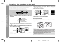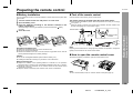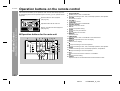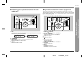
1
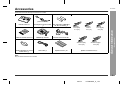
Thank you for purchasing this SHARP product. To obtain the best
performance from this product, please read this manual carefully.
It will guide you in operating your SHARP product.
HOME CINEMA COMMAND
MODEL
HT-CN300W
OPERATION MANUAL
HT-CN300W Home Cinema Command consisting of HT-CN300W (main
unit), CP-CN300WF (front speakers), CP-CN300WC (centre speaker)
and CP-CN300WR (surround speakers).
HT-CN300W
Special notes
z When the ON/STAND-BY button is set at STAND-BY position, mains voltage is still
present inside the unit. When the ON/STAND-BY button is set at STAND-BY
position, the unit may be brought into operation by the timer mode or remote
control.
z This unit contains no user serviceable parts. Never remove covers unless qualified
to do so. This unit contains dangerous voltages, always remove mains plug from
the socket before any service operation and when not in use for a long period.
z The supplied AC adaptor contains no user serviceable parts. Never remove covers
unless qualified to do so. It contains dangerous voltages, always remove mains
plug from the main outlet socket before any service operation or when not in use
for a long period.
z To prevent fire or shock hazard, do not expose this appliance to dripping or
splashing. No objects filled with liquids, such as vases, should be placed on the
apparatus.
- Special notes / Contents -
General Information
Warning:
Contents
„ General Information
Page
Accessories . . . . . . . . . . . . . . . . . . . . . . . . . . . . . . . . . . . . . . . . . . . . . . . . . . . . . . . 2
Precautions . . . . . . . . . . . . . . . . . . . . . . . . . . . . . . . . . . . . . . . . . . . . . . . . . . . . . . . 3
Controls and indicators . . . . . . . . . . . . . . . . . . . . . . . . . . . . . . . . . . . . . . . . . . 4 - 6
„ Connections
Speaker connections . . . . . . . . . . . . . . . . . . . . . . . . . . . . . . . . . . . . . . . . . . . . . 7, 8
Aerial connection . . . . . . . . . . . . . . . . . . . . . . . . . . . . . . . . . . . . . . . . . . . . . . . . . . 8
Remote control sensor connection . . . . . . . . . . . . . . . . . . . . . . . . . . . . . . . . . . . . 8
Connecting other equipment . . . . . . . . . . . . . . . . . . . . . . . . . . . . . . . . . . . . . 9 - 11
Connecting to the AC socket . . . . . . . . . . . . . . . . . . . . . . . . . . . . . . . . . . . . . 12, 13
„ Speaker Installation
Placing the speaker system . . . . . . . . . . . . . . . . . . . . . . . . . . . . . . . . . . . . . . . . . 14
Installing the speakers on the wall . . . . . . . . . . . . . . . . . . . . . . . . . . . . . . . . . . . 15
Notes:
z The letters in brackets contained in the model number indicate the colour of the
product only. Operation and specifications are unaffected.
„ Remote Control
Preparing the remote control . . . . . . . . . . . . . . . . . . . . . . . . . . . . . . . . . . . . . . . . 16
Operation buttons on the remote control . . . . . . . . . . . . . . . . . . . . . . . . . . 17 - 19
Memorising the remote control buttons . . . . . . . . . . . . . . . . . . . . . . . . . . . . 20, 21
„ Basic Operation
Setting the clock . . . . . . . . . . . . . . . . . . . . . . . . . . . . . . . . . . . . . . . . . . . . . . . . . . 22
Display control . . . . . . . . . . . . . . . . . . . . . . . . . . . . . . . . . . . . . . . . . . . . . . . . . . . 23
Sound control . . . . . . . . . . . . . . . . . . . . . . . . . . . . . . . . . . . . . . . . . . . . . . . . . . . . 23
Enjoy Surround Sound (sound mode) . . . . . . . . . . . . . . . . . . . . . . . . . . . . 24 - 26
Listening to the radio . . . . . . . . . . . . . . . . . . . . . . . . . . . . . . . . . . . . . . . . . . . . . . 27
Listening to a memorised station . . . . . . . . . . . . . . . . . . . . . . . . . . . . . . . . . . . . 28
„ Advanced Features
Speaker settings . . . . . . . . . . . . . . . . . . . . . . . . . . . . . . . . . . . . . . . . . . . . . . 29 - 31
Timer and sleep operation . . . . . . . . . . . . . . . . . . . . . . . . . . . . . . . . . . . . . . . 32, 33
„ References
Troubleshooting chart . . . . . . . . . . . . . . . . . . . . . . . . . . . . . . . . . . . . . . . . . . 34, 35
Error indicators and warnings . . . . . . . . . . . . . . . . . . . . . . . . . . . . . . . . . . . . . . . 35
Maintenance . . . . . . . . . . . . . . . . . . . . . . . . . . . . . . . . . . . . . . . . . . . . . . . . . . . . . 35
Specifications . . . . . . . . . . . . . . . . . . . . . . . . . . . . . . . . . . . . . . . . . . . . . . . . . . . . 36
1
02/7/11
HT-CN300W_A_1.fm
Accessories
HT-CN300W
Please confirm that the following accessories are included.
(RADPA6006BGZZ)
Labels for remote control
AC adaptor for remote control
1
1
FM/AM loop aerial
1
"AA" size battery (UM/SUM-3,
R6, HP-7 or similar) 2
Remote control sensor
White
Front (left):
5 m (15')
Green
Centre:
5 m (15')
1
Blue
Surround (left):
15 m (45')
Double-sided tape for remote
control sensor 1
Video cable
1
Speaker cushion
20
Red
Front (right):
5 m (15')
Grey
Surround (right):
15 m (45')
Speaker connection lead
5
Note:
Only the above accessories are included.
2
02/7/11
HT-CN300W_A_1.fm
- Accessories -
1
General Information
Remote control
HT-CN300W
Precautions
„ General
z Please ensure that the equipment is positioned in a well ventilated area and that
there is at least 10 cm (4") of free space along the sides and back. There must
also be a minimum of 15 cm (6") of free space on the top of the unit.
10 cm (4")
10 cm (4")
z Do not remove the outer cover, as this may result
in electric shock. Refer internal service to your
local SHARP service facility.
15 cm (6")
10 cm (4")
z The ventilation should not be impeded by covering
the ventilation openings with items, such as
newspapers, tablecloths, curtains, etc.
z Use the unit on a firm, level surface free from
vibration.
- Precautions -
General Information
z Hold the AC power plug by the head when removing
it from the wall socket, as pulling the lead can
damage internal wires.
z Keep the unit away from direct sunlight, strong
magnetic fields, excessive dust, humidity and
electronic/electrical equipment (home computers,
facsimiles, etc.) which generates electrical noise.
z No naked flame sources, such as lighted candles, should be placed on the
apparatus.
z Attention should be drawn to the environmental aspects of battery disposal.
z This unit should only be used within the range of 5°C - 35°C (41°F - 95°F).
z When carrying the unit by hand, do not hold the subwoofer located on the lower
part. The subwoofer may be damaged.
Correct
Warning:
z Do not place anything on top of the unit.
z Do not expose the unit to moisture, to temperatures higher than 60°C (140°F) or to
extremely low temperatures.
z If your system does not work properly, disconnect the AC power lead from the wall
socket. Plug the AC power lead back in, and then turn on your system.
z In case of an electrical storm, unplug the unit for
safety.
The voltage used must be the same as that specified on this unit. Using this product
with a higher voltage other than that which is specified is dangerous and may result in
a fire or other type of accident causing damage. SHARP will not be held responsible
for any damage resulting from use of this unit with a voltage other than that which is
specified.
„ Volume control
The sound level at a given volume setting depends on speaker efficiency, location,
and various other factors. It is advisable to avoid exposure to high volume levels, to
avoid this do not turn the volume on to full at switch on and listen to music at
moderate levels.
3
02/7/11
HT-CN300W_A_1.fm
Controls and indicators
HT-CN300W
„ Remote control
3
4
5
6
7
8
9
10
11
12
13
14
17
18
19
20
21
22
23
15
15
16
16
24
25
26
1. On/Stand-by Button . . . . . . . . . . . . . . . . . . . . . . . . . . . . . . . . . . . . . 13
2. Operation Buttons for Other Equipment . . . . . . . . . . . . . . . . . . . . . 18
3. Remote Control Transmitter . . . . . . . . . . . . . . . . . . . . . . . . . . . . . . . 16
4. Sound Mode Select Buttons . . . . . . . . . . . . . . . . . . . . . . . . . . . . . . 26
5. Dynamic Sound Select Button . . . . . . . . . . . . . . . . . . . . . . . . . . . . . 26
6. Remote Control Sensor for Learn Function . . . . . . . . . . . . . . . . . . 20
7. Speaker Set Up Button . . . . . . . . . . . . . . . . . . . . . . . . . . . . . . . . . . . 29
8. Clear Button . . . . . . . . . . . . . . . . . . . . . . . . . . . . . . . . . . . . . . . . . 21, 28
9. Learn Indicators . . . . . . . . . . . . . . . . . . . . . . . . . . . . . . . . . . . . . . . . 20
10.Volume Up and Down Buttons . . . . . . . . . . . . . . . . . . . . . . . . . . . . . 23
11.DVD Button . . . . . . . . . . . . . . . . . . . . . . . . . . . . . . . . . . . . . . . . . . . . 18
12.Video-1 Button . . . . . . . . . . . . . . . . . . . . . . . . . . . . . . . . . . . . . . . . . . 18
13.Tuner/Band Button . . . . . . . . . . . . . . . . . . . . . . . . . . . . . . . . . . . . . . 27
14.Video-2/Auxiliary Button . . . . . . . . . . . . . . . . . . . . . . . . . . . . . . . . . 18
15.Memory 1/2 Buttons for Other Equipment . . . . . . . . . . . . . . . . . . . 19
16.Label Sealing Area . . . . . . . . . . . . . . . . . . . . . . . . . . . . . . . . . . . . . . 21
17.Clock Button . . . . . . . . . . . . . . . . . . . . . . . . . . . . . . . . . . . . . . . . . . . 22
18.Memory Button . . . . . . . . . . . . . . . . . . . . . . . . . . . . . . . . . . . . . . . . . 28
19.Timer/Sleep Button . . . . . . . . . . . . . . . . . . . . . . . . . . . . . . . . . . . . . . 32
20.TV Screen Display Button . . . . . . . . . . . . . . . . . . . . . . . . . . . . . . . . 23
21.Dimmer Button . . . . . . . . . . . . . . . . . . . . . . . . . . . . . . . . . . . . . . . . . 23
22.Extra Bass/Demo Mode Button . . . . . . . . . . . . . . . . . . . . . . . . . 13, 23
23.Equaliser Mode Selector Button . . . . . . . . . . . . . . . . . . . . . . . . . . . 23
24.Cursor Button . . . . . . . . . . . . . . . . . . . . . . . . . . . . . . . . . 22, 27, 29, 32
25.Enter Button . . . . . . . . . . . . . . . . . . . . . . . . . . . . . . . . . . . . . 22, 29, 32
26.Learn/Transmit Selector Switch . . . . . . . . . . . . . . . . . . . . . . . . . . . . 20
27.3.6 V DC Input Socket . . . . . . . . . . . . . . . . . . . . . . . . . . . . . . . . . . . . 12
28.Memory 1/2 Selector Switch . . . . . . . . . . . . . . . . . . . . . . . . . . . . 19, 20
27
28
4
02/7/11
HT-CN300W_A_1.fm
- Controls and indicators -
2
General Information
Reference page
1
HT-CN300W
Controls and indicators (continued)
„ Main unit (with subwoofer)
11
1
2
3
4 5 6 7
12
Front
- Controls and indicators -
General Information
8
9
10
Reference page
Back
13
14
11.Power Indicator . . . . . . . . . . . . . . . . . . . . . . . . . . . . . . . . . . . . . . . . .13
12.On/Stand-by Button . . . . . . . . . . . . . . . . . . . . . . . . . . . . . . . . . . . . . .13
22
23
15
16
17
18
1. Memory Indicator
2. Timer Play Indicator
3. Sleep Indicator
4. Extra Bass Indicator
5. Digital Theatre System Indicator
6. FM Stereo Mode Indicator
7. FM Stereo Receiving Indicator
8. Dolby Pro Logic II Indicator
9. Dolby Virtual Indicator
10.Dolby Digital Indicator
24
25
26
27
19
20
13.Remote Control Sensor Socket . . . . . . . . . . . . . . . . . . . . . . . . . . . . .8
14.TV Type Switch . . . . . . . . . . . . . . . . . . . . . . . . . . . . . . . . . . . . . . . . . .11
15.TV Monitor Output Sockets . . . . . . . . . . . . . . . . . . . . . . . . . . . . . . . .10
16.DVD Video Input Sockets . . . . . . . . . . . . . . . . . . . . . . . . . . . . . . . . .10
17.Video and Audio Input Sockets (VIDEO 2) . . . . . . . . . . . . . . . . . . .11
18.Video and Audio Input Sockets (VIDEO 1) . . . . . . . . . . . . . . . . . . .11
19.AC Voltage Selector . . . . . . . . . . . . . . . . . . . . . . . . . . . . . . . . . . . . . .12
20.Subwoofer
21.AC Power Lead . . . . . . . . . . . . . . . . . . . . . . . . . . . . . . . . . . . . . . . . . .12
22.DVD Optical Digital Audio Input Socket . . . . . . . . . . . . . . . . . . . . . .10
23.DVD Coaxial Digital Audio Input Socket . . . . . . . . . . . . . . . . . . . . .10
24.Span Selector Switch . . . . . . . . . . . . . . . . . . . . . . . . . . . . . . . . . . . .13
25.FM/AM Loop Aerial Socket . . . . . . . . . . . . . . . . . . . . . . . . . . . . . . . . .8
26.Video and Audio Output Sockets (VIDEO 1) . . . . . . . . . . . . . . . . . .11
27.Auxiliary Audio Input Sockets . . . . . . . . . . . . . . . . . . . . . . . . . . . . .11
28.Speaker Terminals . . . . . . . . . . . . . . . . . . . . . . . . . . . . . . . . . . . . . . . .8
28
21
5
02/7/11
HT-CN300W_A_1.fm
HT-CN300W
„ Front/Centre/Surround speakers
Side
2
1
4. Mounting Slot . . . . . . . . . . . . . . . . . . . . . . . . . . . . . . . . . . . . . . . . . . 15
5. Speaker Terminals . . . . . . . . . . . . . . . . . . . . . . . . . . . . . . . . . . . . . . . 8
6. Mounting Screw Holes . . . . . . . . . . . . . . . . . . . . . . . . . . . . . . . . . . . 15
Speaker cushion:
3
Attach the cushions to the bottom of the speakers to prevent
them from sliding.
Bottom
5
4
6
„ Remote control sensor
Reference page
1. Remote Sensor . . . . . . . . . . . . . . . . . . . . . . . . . . . . . . . . . . . . . . . . . 16
2. Remote Control Indicator . . . . . . . . . . . . . . . . . . . . . . . . . . . . . . . . . 16
3. Remote Sensor Connection Plug . . . . . . . . . . . . . . . . . . . . . . . . . . . 8
Double-sided tape for remote control sensor:
You can fix the remote control sensor with the supplied tape.
1
2
Caution:
3
z Carefully choose where you place the remote control sensor as the adhesive tape
may damage or peel the surface coating when the tape is removed.
z Never locate the remote control sensor in an unstable place. Otherwise it may fall.
Note:
Fix the remote control sensor on a flat surface.
6
02/7/11
HT-CN300W_A_1.fm
- Controls and indicators -
Front Speaker (right): Red
Front Speaker (left): White
Centre Speaker: Green
Surround Speaker (right): Grey
Surround Speaker (left): Blue
General Information
Front
Reference page
1. Full-Range Speaker
2. Angle Adjusting Lever . . . . . . . . . . . . . . . . . . . . . . . . . . . . . . . . . . . 15
3. Label indication
HT-CN300W
Speaker connections
Centre
speaker
Front speaker
(right)
Connections
Red
Black
Red
Green
- Speaker connections -
Black
Front speaker
(left)
Black
Red
Red
White
Main unit
(with subwoofer)
Green
Surround speaker
(right)
Black
Red
White
Surround speaker
(left)
Red
Black
Grey
Blue
Blue
Grey
7
02/7/11
Red
HT-CN300W_A_2.fm
Aerial connection
The speaker terminals on the main unit, the tube and plugs of the speaker lead, and
speaker labels are distinguished by colour.
Connect the speaker and the unit by matching the colours.
Connect the speaker wires to the speakers first, then to the unit.
HT-CN300W
Connect the FM/AM loop aerial to
the ANTENNA socket.
Label
Position the FM aerial wire and rotate the AM loop aerial for optimum reception.
Place the AM loop aerial on a shelf, or attach it to a stand or on a wall with screws
(not supplied).
Recess
Notes:
Black
z Placing the aerial on the unit, or near the AC power lead or the remote sensor may
cause noise pickup. Place the aerial away from the unit for better reception.
z Do not connect the attached FM aerial to an external FM aerial. Otherwise, trouble
may occur.
Red
Installing the AM loop aerial:
< Attaching to the wall >
Main unit
Screws
(not supplied)
Wall
Label
Speaker plug
Plug in with the rising
side facing up.
Caution:
z
z
z
z
Only the supplied speakers should be used with this unit.
Make sure to connect the speakers after unplugging the unit.
Do not mistake and , and right and left terminals of the speaker leads.
Do not let the bare speaker wires touch each
other.
Remote control sensor connection
Connect the plug of the remote
control sensor and push the plug
cover until it clicks.
Plug
Connections
< Assembling >
Tube
Plug cover
Removing the remote control sensor:
Push the upper and lower sides of the plug cover and take the
plug off the unit to disconnect the remote control sensor.
Push
Push
z Do not stand or sit on the speakers. You may be injured.
z Insert the speaker plug fully with the rising side facing up.
z Hold the speaker plug when removing it from the unit. Pulling the lead may cause
breakage.
Caution:
z Hold the connection plug of the remote control sensor when removing it from the
unit. Pulling the lead may cause breakage.
z Make sure of the top and bottom of the plug when plugging in the remote control
sensor.
8
02/7/11
HT-CN300W_A_2.fm
- Speaker / Aerial / Remote control sensor connections -
Speaker
HT-CN300W
Connecting other equipment
To enjoy images or music, connect other equipment to the main unit with the supplied video cable for TV or you can purchase commercially available cables.
Only one video cable is supplied with this unit.
Optical digital audio cable
TV
S-video cable
or
Coaxial digital audio cable
DVD player
Video cable (supplied)
S-video cable
Connections
- Connecting other equipment -
(See page 10.)
Video cable
Camcorder,
Satellite receiver, etc.
(See page 10.)
Video cable
Video cable
Audio cable
(See page 11.)
VCR
Audio cable
Video cable
Tape deck, etc.
Audio cable
Audio cable
(See page 11.)
(See page 11.)
Video cable:
Yellow
Yellow
Audio cable:
White (Left)
White (Left)
Red (Right)
Red (Right)
9
02/7/11
HT-CN300W_A_2.fm
HT-CN300W
„ Connecting the DVD player
Caution:
Use the video cable or the S-video cable for receiving images. The S-video cable can
realise clearer images. For audio, connect with the optical digital cable or the coaxial
digital cable.
Turn off all other equipment before making this connection.
Notes:
To connect to the video socket with the video cable:
z Refer to the operation manual of the equipment to be connected.
z Insert the plugs fully to avoid fuzzy pictures or noise.
Coaxial digital
audio cable
Optical digital audio cable
Video cable (supplied)
To video input socket
Video cable
TV
DVD player
To video output socket
Note:
When connecting a DVD player with a video cable, be sure to use another video
cable for the TV.
S-video cable
To S-video input socket
Notes:
To connect to the S-video socket with the S-video cable:
z Change the TV input in accordance with the connected socket.
z Do not connect other equipment between the TV and this unit. If they are
connected via a VCR, pictures may be distorted.
z When the video and S-video cables are both connected, the images from the Svideo input socket appears on your TV.
Coaxial digital
audio cable
Optical digital audio cable
DVD player
Caution:
The settings appear only when the TV is connected with a video cable. They
will not appear when the TV is connected with an S-video cable.
During the tuner or auxiliary mode, the TV screen display will not be shown.
(See page 23 for the TV screen display.)
Example: TV screen display
S-video cable To S-video output socket
Connections
Connect the TV to the main unit with the supplied video cable. If your TV has S-video
input socket, connect the commercially available S-video cable to enjoy clearer
images on DVDs.
- Connecting other equipment -
„ Connecting the TV
Note:
When connecting a DVD player with an S-video cable, be sure to use another S-video
cable for the TV. This unit cannot convert the S-video signal into the video or other
signals.
Switching the DVD audio input:
Switch the DVD's audio signal with the remote control according to the connected
socket, "DIG1" (optical) or "DIG2" (coaxial) (see page 18).
Optical digital socket cap:
When using the optical digital socket, remove the cap
first. After using the socket, replace the cap.
10
02/7/11
HT-CN300W_A_2.fm
HT-CN300W
Connecting other equipment (continued)
„ Connecting the VCR (VIDEO 1)
„ Connecting the tape deck, etc. (AUX)
Audio cable
Video cable
Audio cable
To video
output socket
To audio
output sockets
To audio output sockets
Tape deck, etc.
VCR
Connections
- Connecting other equipment -
Audio cable
To video
input socket
To audio
input sockets
Video cable
Notes:
z Connect the unit and the TV with a video cable. The image of the equipment
connected to the VIDEO 1 IN sockets does not appear on the TV even if it is
connected with an S-video cable.
z The image and sound are not emitted from the VIDEO 1 OUT sockets when the
equipment is connected to the DVD or VIDEO 1 IN sockets.
If connected to the VIDEO 2 IN sockets, they are emitted from the VIDEO 1 OUT
sockets. If connected to the AUX IN sockets or whilst in the tuner mode, only the
sound is emitted.
„ Selecting the colour TV system
There are two colour TV systems: PAL and NTSC.
Select either PAL or NTSC according to the TV connected.
To select the colour TV system:
Set the TV TYPE switch (on the rear panel) to PAL or NTSC.
„ Connecting the camcorder, satellite
receiver, etc. (VIDEO 2)
To video
output socket
Camcorder,
Satellite receiver, etc.
Audio cable
Video cable
To audio
output sockets
Note:
Connect the unit and the TV with a video cable. The image of the equipment
connected to the VIDEO 2 IN sockets does not appear on the TV even if it is
connected with an S-video cable.
Notes:
z This unit can display on the TV its current speaker and mode settings when
connected to the TV via a video cable in the DVD or VIDEO mode.
However, if TV TYPE is set to NTSC when PAL system TV is connected, or vice
versa, the settings will not show correctly. (The display may show in black and white
or may be distorted.) Set accordingly.
z Set the colour system (PAL/NTSC) of your DVD or VCR according to the
connecting TV.
If the settings of TV, DVD/VCR and TV TYPE of this product do not match, pictures
will not show correctly or will be scrambled.
11
02/7/11
HT-CN300W_A_2.fm
Connecting to the AC socket
HT-CN300W
„ Setting the AC voltage selector
„ Plugging in the remote control
Check the setting of the AC voltage selector located on the rear panel before
plugging the unit into a wall socket. If necessary, adjust the selector to correspond to
the AC power voltage used in your area.
Before connecting:
Turn the selector with a screwdriver until the appropriate voltage
number appears in the window (110 V, 127 V, 220 V or 230 V - 240 V AC).
Check the setting of the AC voltage selector located on the AC adaptor. If necessary,
adjust the selector to correspond to the AC power voltage used in your area.
Turn the selector to the appropriate voltage number using a screwdriver (110 V
- 127 V or 220 V - 240 V).
„ Plugging in the main unit
110V 127V 220V 240V
Wall socket
(230 - 240 V, 50/60 Hz)
OFF
Notes:
Note:
Unplug the AC power lead from the wall socket if the unit will not be in use for a
prolonged period of time.
z You can operate the remote control with batteries in areas where the AC adaptor
lead cannot reach (see page 16).
z Remove the AC adaptor from the AC socket if the unit will not be in use for a
prolonged period of time.
z Use only the supplied AC adaptor. Another adaptor may cause an electric shock or
fire.
z If the AC adaptor or its power supply lead is damaged, replace the AC adaptor
with the same type (RADPA6006BGZZ) in order to avoid any hazards.
Connections
Wall socket
(230 - 240 V, 50/60 Hz)
- Connecting to the AC socket -
To 3.6 V DC
input socket
After making all connections, plug the unit. If you plug the unit first, the
unit will enter the demonstration mode (see page 13).
12
02/7/11
HT-CN300W_A_3.fm
HT-CN300W
Connecting to the AC socket (continued)
„ Setting the FM/AM span selector
„ Demonstration mode
The first time the unit is plugged in, the unit will enter the demonstration mode. You
will see words scroll.
To cancel the demonstration mode:
Connections
- Connecting to the AC socket -
When the unit is in the power stand-by mode (demonstration mode), press the XBASS button. The demonstration mode will be cancelled and the display will
disappear.
To return to the demonstration mode:
When the unit is in the power stand-by mode, press the X-BASS button again.
Note:
The International Telecommunication Union (ITU) has established that member
countries should maintain either a 10 kHz or 9 kHz interval between broadcasting
frequencies of AM stations and 100 kHz or 50 kHz for FM stations. The illustration
shows the 50/9 kHz zones (regions 1 and 3), and the 100/10 kHz zone (region 2).
Before using the unit, set the SPAN SELECTOR switch (on the rear panel) to the
interval (span) of your area.
To change the tuning zone:
1
2
3
Unplug the unit.
Set the SPAN SELECTOR switch (on the rear panel) as follows.
z For 50 kHz FM interval (9 kHz in AM) 50/9
z For 100 kHz FM interval (10 kHz in AM) 100/10
Plug in the AC power lead.
When the power is on, the X-BASS button can be used to select the extra bass mode
(see page 23).
„ To turn the power on
Press the ON/STAND-BY button on the main unit or the ON/ (STAND-BY) button on
the remote control.
To set the unit to stand-by mode:
Press the ON/STAND-BY button on the main unit or the ON/ (STAND-BY) button on
the remote control again.
Power indicator
Caution:
This operation will erase all data stored in memory and restore various settings to the
initial status (default).
Notes:
z For the operation range and direction of the remote control, see page 16.
z When turning on the power right after it is set to the stand-by mode, wait a few
seconds.
13
02/7/11
HT-CN300W_A_3.fm
Placing the speaker system
The best surround effect will be achieved by placing each speaker at the same
distance from the listening position.
It is recommended to arrange the speakers as shown below.
HT-CN300W
The supplied speakers may be placed beside or near the TV as they are magnetically
shielded. However, colour variation may occur, depending on the type of the TV.
If colour variation occurs...
Front
speaker (right)
Turn off the TV (from the power switch).
After 15 - 30 minutes, turn the TV on again.
If the colour variation is still present...
Move the speakers further away from the TV.
Refer to the user's manual of the TV for details.
Main unit
(subwoofer)
Surround
speaker (left)
Speaker Installation
Example of speaker locations:
Surround
speaker (right)
Centre speaker
Same distance
Front speaker (left)
Same distance
Front speaker (right)
- Placing the speaker system -
Front
speaker (left)
Centre
speaker
Notes:
z Place the TV halfway between the front speakers.
z It is recommended that the centre speaker be placed near the television.
z Place the surround speakers at a position just above the height of your ears.
14
02/7/11
HT-CN300W_A_3.fm
HT-CN300W
Installing the speakers on the wall
Front, centre and surround speakers can be mounted on the wall and their angle can
be adjusted. Each speaker needs 3 screws to be mounted (not supplied).
3
Raise the speaker the most upward. (Refer to "Changing the
speaker angle" for details.)
The design of the speakers allows them to be hung on the wall.
Be sure to use the type and size of the screw that are shown below.
4
Drive two screws into the wall.
3.2 mm (1/8")
5 mm (3/16")
Speaker Installation
- Installing the speakers on the wall -
Min. 22 mm (7/8")
1
9 mm (3/8")
Label
Drive one screw into the wall for each speaker, as shown in the
illustration.
3.5 mm (9/64")
Wall mounting screw
(not supplied)
Label
Use the round labels for hiding mounting screws.
5
Perform steps 1 - 4 to mount other speakers.
Changing the speaker angle:
Whilst holding down the angle adjusting lever, move the speaker to the marking and
then release the lever.
The speaker angle can be adjusted in 5 levels.
Wall surface
Min. 18.5 mm (23/32")
z Make sure that both the screw and the wall can support a load of 20 kg (45 lbs.).
z Drive the screw, so the screw head extends about 3.5 mm (9/64") out from the
wall.
2
Install the speaker on the wall by inserting the screw head into the
slot on the back of the speaker.
Mark
Recess
Caution:
Wall surface
Set the speaker lead in the recess, preventing it from being caught between the
wall and the speaker.
Check the stability of the ceiling or wall fully. Sharp is not liable for accidents
caused by insufficient stability of the ceiling or wall, or improper mounting.
The speaker may fall due to unstable mounting.
If you need any assistance, contact the dealer you purchased the system from.
The following may cause personal injury or speaker damage.
Applying any other load to the fittings than the speaker.
Modification or change of the fittings.
Stepping on or hanging from the speakers. Especially pay attention to small children.
15
02/7/11
HT-CN300W_A_3.fm
Preparing the remote control
HT-CN300W
„ Battery installation
„ Test of the remote control
You can operate the remote control with batteries in areas where the AC power lead
cannot reach.
Point the remote control directly at the remote sensor.
1
2
3
The remote control can be used within the range shown below:
Turn the remote control over and place it on a soft cloth.
Open the battery cover.
Insert the batteries according to the direction indicated in the
battery compartment.
Close the cover.
Remote sensor
0.2 m - 6 m
(8" - 20')
15
Remote control
indicator
15
20
20
Precautions for battery use:
z Replace all old batteries with new ones at the same time.
z Do not mix old and new batteries.
z Remove the batteries if the unit is not to be used for long periods of time. This will
prevent potential damage due to battery leakage.
Caution:
z Do not use rechargeable batteries (nickel-cadmium battery, etc.).
z Installing the batteries incorrectly may cause the unit to malfunction.
Note:
Exposing the remote sensor to strong light may interfere with operation. Change the
lighting or the direction of the remote control sensor.
„ How to open the remote control cover
To access the Memory 1/2 buttons, open the remote control cover.
Remote Control
4
battery
- Preparing the remote control -
When inserting or removing the batteries, push them towards the
terminals.
z Press the ON/ (STAND-BY) button. Does the power turn on? Now, you can enjoy
your system.
z When the signal is received, the remote control indicator will flash. Whilst in the
dimmer mode (page 23), it will not flash or light.
Notes concerning use:
z Replace the batteries if the operating distance is reduced or if the operation
becomes erratic. Purchase 2 "AA" size batteries (UM/SUM-3, R6, HP-7 or similar).
z Periodically clean the transmitter on the remote control and the remote control
sensor with a soft cloth.
z Keep the remote control away from moisture, heat, shock, and vibrations.
Note:
You can control the DVD, VCR, etc. with this remote control (see page 19).
16
02/7/11
HT-CN300W_A_3.fm
HT-CN300W
Operation buttons on the remote control
This remote control allows you to operate the main unit and other Sharp equipment.
By memorising remote control operations (learn function), you can operate various
equipment.
Operation buttons for other equipment
(See page 18.)
1
2
3
4
5
Remote Control
- Operation buttons on the remote control -
Operation buttons for the main unit
Memory 1/2 buttons for other equipment
(See page 19.)
6
7
8
9
„ Operation buttons for the main unit
10
11
1
2
3
4 5 6
7 8 9
ON/ (STAND-BY)
Sets the power to "ON" or "STAND-BY".
12
13
Changes the settings of time, tuner, timer/sleep operations, and speakers.
VOLUME
Decreases the volume.
VOLUME
Increases the volume.
STANDARD
Sets the sound mode to "STANDARD".
DYNAMIC SOUND
Switches the dynamic sound.
SET UP
Changes the speaker setting.
CLEAR
Deletes the tuner pre-selections.
CLOCK
Sets or displays the clock time.
MEMORY
Presets the tuner.
TIMER/SLEEP
Sets the power to "ON" or "STAND-BY" at the desired time.
DIMMER
Adjusts the brightness of the main unit display.
DISPLAY
Switches the TV display.
14
10
11
12
13
Changes the settings of tuner and speakers.
15
Changes the settings of time, tuner, timer/sleep operations, and speakers.
16 ENTER
Validates the settings of time, timer/sleep operations, and speakers.
17
Changes the settings of tuner and speakers.
18 2CH
Switches the sound mode to "VIRTUAL" or "STEREO".
19 EQ
Changes the tone setting.
20 X-BASS
Adjusts the bass or activates/deactivates the demonstration mode.
14 15 16 17 18 19 20
17
02/7/11
HT-CN300W_A_3.fm
HT-CN300W
„ Operation buttons for other equipment
The remote control is set at the factory to operate the Sharp's DVD, TV and VCR.
To operate Sharp products or other companies' equipment that cannot be controlled
by the default remote control, you can memorise their remote control operations
(learn function) (see page 20).
1
2 3
3 4 5 6
4
7 8 9
1
DVD
Used when the unit is set to DVD. Switch the setting according to the connected
sound source by pressing it repeatedly.
1
2
10
DVD ON/ (STAND-BY)
Sets the DVD power to "ON" or "STAND-BY".
TV ON/ (STAND-BY)
Sets the TV power to "ON" or "STAND-BY".
3
Skips DVD chapters.
4
(Optical)
2
3
4
(Coaxial)
TUNER/BAND
Selects the tuner function or switches the frequency band.
VIDEO-2/AUX
Selects the "VIDEO-2" or "AUX" mode.
VIDEO-1
Selects the "VIDEO-1" mode.
Skips DVD chapters.
5
Stops the DVD player.
Remote Control
1 2
- Operation buttons on the remote control -
„ Switching the operation buttons for the
main unit
6
Plays back the DVD.
VCR ON/ (STAND-BY)
Sets the VCR power to "ON" or "STAND-BY".
8 TV INPUT
Switches the TV input.
9 MENU
Displays the DVD menu.
10 RETURN
Goes back to the previous screen.
7
18
02/7/11
HT-CN300W_A_3.fm
HT-CN300W
Operation buttons on the remote control (continued)
„ Memory 1/2 buttons for other equipment
Memory 1 buttons:
The remote control is set at the factory to operate the Sharp's DVD, TV and VCR.
To operate Sharp products or other companies' equipment that cannot be controlled
by the default remote control, you can memorise their remote control operations
(learn function) (see page 20).
Remote Control
- Operation buttons on the remote control -
Set the MEMORY 1/2 selector switch to MEMORY 1 to use the Memory 1 buttons.
Initial setting for Memory 1 buttons:
1
2
3
4
5
Memory 2 buttons:
6
No functions are stored at the factory setting. Memorise the remote control signals
(learn function) of your equipment before use (see page 20).
7
Set the MEMORY 1/2 selector switch to MEMORY 2 to use the Memory 2 buttons.
8
9
10
11
12
OPEN
13
14
1
2
3
4
13
14
15
16
5
7
17
19
6
8
18
20
9 10 11 12
21 22 23 24
TV/VCR
Switches the input to TV or VCR.
VCR CH
Switches up the VCR channels.
TV VOL
Turns up the TV volume.
TV CH
Switches up the TV channels.
TV VOL
Turns down the TV volume.
TV CH
Switches down the TV channels.
VCR CH
Switches down the VCR channels.
VCR
Pauses VCR.
VCR
Rewinds the VCR rapidly.
VCR
Advances the VCR rapidly.
VCR
Stops the VCR.
VCR
Plays the VCR.
AUDIO
Switches the DVD sound.
SET UP
Changes the DVD settings.
15
Selects the DVD menu.
16 DISPLAY
Switches the DVD display.
17
Selects the DVD menu.
18 SUB
Switches the subtitle of a DVD.
19 ENTER
Validates the menu.
20
Selects the DVD menu.
21 ANGLE
Switches the angle of the DVD images.
22 ZOOM
Zooms the DVD images.
23
Selects the DVD menu.
24 TOP
Displays the top menu of the DVD.
For details, refer to the operation manual attached to the other equipment.
19
02/7/11
HT-CN300W_A_3.fm
Memorising the remote control buttons
You can assign only one function to each button. If you assign two functions to the
button, the newer one will be memorised (learn function).
4
„ Memorising operations in the Memory 2
buttons for other equipment
Within 10 seconds, press down for more than 2 seconds the
desired button on the remote control supplied with other
equipment to send the signal to the marking.
Angle and distance
The same buttons are used for both Memory 1 and 2 operations. To store signals in
Memory 1 buttons, set the MEMORY 1/2 selector switch to MEMORY 1, and for
Memory 2 buttons, set the switch to MEMORY 2.
5 cm - 10 cm (2" - 4")
10˚
Set the MEMORY 1/2 selector switch to MEMORY 2.
Lit Goes off
Lit Lights up
mark
2
Move the LEARN/TRANSMIT selector switch to LEARN.
The red learn indicator will light up. Though the red and green learn indicators
light up alternately after approx. 15 seconds, you can go on to the next step.
Lights up
3
If the signal is not memorised correctly, the
red learn indicator will flash. Perform the
operations from step 3 again.
Alternately light up
Press down the desired button on the remote control for 2 seconds
or more.
The green learn indicator will flash (the red indicator remains lit).
Lit Flashes
5
6
Flashes
Repeat steps 3 and 4 to memorise other buttons.
Remote Control
When the signal is sent to the remote control of the unit, the green indicator will
go off. When memorisation is completed, it will light up.
- Memorising the remote control buttons -
1
HT-CN300W
After memorisation is completed, move the LEARN/TRANSMIT
selector switch to TRANSMIT.
You can use the remote control.
Notes:
z You cannot store all the button operations by pressing only one button on the
remote control of other equipment. Memorise them one by one.
z After storing operation is completed, check that other equipment works correctly
with the remote control.
z Some functions cannot be memorised depending on other equipment.
20
02/7/11
HT-CN300W_A_3.fm
HT-CN300W
Memorising the remote control buttons (continued)
Memorising operations in the Memory 1 buttons for other equipment:
Set the MEMORY 1/2 selector switch to MEMORY 1 and perform steps 2 - 6 in
"Memorising operations in the Memory 2 buttons for other equipment" (see page 20).
Note:
If a new function is memorised, the default operation on the button will be cleared.
„ Initialising the remote control buttons
You can delete memorised functions and restore the buttons to the factory settings.
1
Move the LEARN/TRANSMIT selector switch to LEARN.
The red learn indicator will light up. Though the red and green learn indicators
light up alternately after approx. 15 seconds, you can go on to the next step.
Remote Control
- Memorising the remote control buttons -
Using the supplied labels:
Lights up
Main features are already printed on the labels. Write in other operations as you
prefer.
2
Alternately light up
Press the ON/ (STAND-BY) and CLEAR buttons simultaneously
for more than 3 seconds.
Initialisation is completed when the red and green learn indicators light up
alternately and then the red learn indicator lights up.
Alternately light up
Lights up
Memorising operations in the operation buttons for other equipment:
1
2
Move the LEARN/TRANSMIT selector switch to LEARN.
Press down the desired button on the remote control for 2 seconds or more.
Registrable buttons
3
Goes off
Move the LEARN/TRANSMIT selector switch to TRANSMIT.
z You can use the remote control.
z Operation buttons and Memory 1 buttons for other equipment will return to the
factory setting.
Caution:
3
Perform steps 4 - 6 in "Memorising operations in the Memory 2 buttons for other
equipment" (see page 20).
You cannot initialise only one button. If initialisation is performed, all the stored
functions will be cleared.
21
02/7/11
HT-CN300W_A_3.fm
Setting the clock
By setting the unit on time, you can use it both as a clock and as a timer.
HT-CN300W
4
Press the
or
ENTER button.
button to adjust the hour and then press the
z Press the or button once to advance the time by 1 hour. Hold it down to
advance continuously.
z When the 12-hour display is selected, "AM" will change automatically to "PM".
3
Press the or button to select the 24-hour or 12-hour display and
then press the ENTER button.
Press the CLOCK button and within 5 seconds, press the ENTER
button.
To confirm the time display:
Press the CLOCK button.
The time display will appear for about 5 seconds.
When the unit is set to DVD or VIDEO, the time also
appears on the TV screen.
Note:
The "CLOCK" or time will flash at the push of the CLOCK button when the AC power
supply is restored after a power failure or unplugging the unit.
Readjust the clock.
- Setting the clock -
Press the ON/ (STAND-BY) button to turn the power on.
button to adjust the minutes and then press the
z Press the or button once to advance the time by 1 minute. Hold it down
to change the time in 5-minute intervals.
z The hour will not advance even if minutes advance from "59" to "00".
z The clock starts from "0" second. (Seconds are not displayed.)
In this example, the clock is set for the 24-hour (0:00) display.
1
2
Press the or
ENTER button.
Basic Operation
5
To readjust the clock:
Perform "Setting the clock" from step 1. If the time display is flashing, step 3 (for selecting
the 24-hour or 12-hour display) will be skipped.
"0:00"
"AM 12:00"
"AM 0:00"
The 24-hour display will appear. (0:00 - 23:59)
The 12-hour display will appear. (AM 12:00 - PM 11:59)
The 12-hour display will appear. (AM 0:00 - PM 11:59)
To change the 24-hour or 12-hour display:
1
2
Note that this can only be set when the unit is first installed or it has been reset (see
page 35).
Clear all the programmed contents. [Refer to "Clearing all the memory (reset)" on
page 35 for details.]
Perform "Setting the clock" from the beginning.
Note:
Setting the clock cancels the demonstration mode automatically.
22
02/7/11
HT-CN300W_A_4.fm
HT-CN300W
Display control
Sound control
„ Volume control
Press the VOLUME
decreasing.
button to increase the volume and the VOLUME
Main unit
0 1
button for
2 ..... 29 30 MAXIMUM
Basic Operation
- Display control / Sound control -
TV screen
„ To change the display brightness (2 levels)
You can switch the brightness of the main unit display by pressing the DIMMER
button.
„ Bass control
When the X-BASS button is pressed, the unit will enter the extra bass mode which
emphasises the bass frequencies. To cancel the extra bass mode, press the X-BASS
button.
Main unit
Dimmed (Dimmer mode)
Brightened
TV screen
„ TV screen display
By pressing the DISPLAY button whilst in the DVD or VIDEO mode, you can check
the status or setting on the TV screen.
Example: TV screen display
Bass frequencies are
emphasised.
Cancelled.
„ Equaliser
When the EQ button is pressed, the current mode setting will be displayed. To
change to a different mode, press the EQ button repeatedly until the desired sound
mode appears.
Caution:
FLAT
The sound is not modified.
ROCK
Bass and treble are emphasised.
POPS
Bass and treble are slightly emphasised.
JAZZ
Treble is cut a little.
CLASSIC
This unit can display on the TV its current speaker and mode settings when in the
DVD or VIDEO mode, but not if connected to the TV via an S-video cable. This
function is only available via the Video cable connection.
VOCAL
Treble is reduced a lot.
Vocals (midrange tones) are emphasised.
Note:
Bass control and equaliser are enabled only when the sound mode is set to
"STEREO" or "VIRTUAL" (see page 26).
23
02/7/11
HT-CN300W_A_4.fm
Enjoy Surround Sound (sound mode)
HT-CN300W
The sound effect is activated when the Dolby Digital and DTS signals below are sent from the digitally connected DVD player, etc. When using other 2ch systems (analogue,
etc.), Dolby Pro Logic II function is activated.
DVD player
Dolby Digital
Dolby Pro Logic II
2ch signals (analogue, etc.)
Types of surround
Source
Dolby Digital
Contents
Switchable sound
mode
One of the digital audio systems for theatrical use. You can
enjoy the stereophonic effect in the home theatre system.
The disc recorded in the Dolby Digital system is recognised
by this unit automatically when it is played back.
Disc with this trademark
DTS (Digital
Systems)
Theater
Stereo
One of the digital audio systems for theatrical use. As the
sound quality is emphasised, you can enjoy the realistic
sound effect in the home theatre system. The disc recorded
in the DTS system is recognised by this unit automatically
when it is played back.
Disc with this trademark
Dolby Pro Logic II
Stereo-recorded discs and videotapes
Standard
(Dynamic sound)
Virtual
Standard
(Dynamic sound)
Virtual
Basic Operation
VCR, etc.
- Enjoy Surround Sound (sound mode) -
DTS
Dolby Digital or DTS signals
Stereo
When playing a stereo-recorded disc or video tape, it is
Standard
recognised by the Dolby Pro Logic II function and the sound
(Dynamic sound)
is changed to the 5.1ch digital surround sound automatically. Virtual (*)
A more natural sound effect can be achieved.
Stereo (*)
If (*) is selected, the "
" indicator goes out.
24
02/7/11
HT-CN300W_A_4.fm
HT-CN300W
Enjoy Surround Sound (sound mode) (continued)
Acoustic effect
Dolby Digital and DTS:
The input signal is recognised automatically and the unit's indicator appears.
Standard
Basic Operation
- Enjoy Surround Sound (sound mode) -
The maximum of 5.1ch surround sound
is reproduced to provide threedimensional effect. This unit
automatically emits the 5.1ch sound
according to the recorded audio signal.
"STANDARD" appears on the display
of the unit and TV screen.
Dynamic sound
You can enjoy normal surround sound with various scenes.
MOVIE:
MUSIC:
NIGHT:
The bass level is increased for powerful sound effect.
You can enjoy lively sound by producing the articulate sound.
Soft but powerful sound is achieved even at low volumes.
Dolby Pro Logic II:
z The indicator appears on the display of the main unit when the 2ch signals are
entered to extend them to the 5.1ch surround sound.
z Even the 2ch sound recorded with Dolby Digital will be extended to the 5.1ch.
Notes:
z When the surround mode is set to "STANDARD", the sound of monaural signals is
heard only from the centre speaker.
z When the surround mode is set to "VIRTUAL", the same monaural sound is
reproduced in both the front right and front left channels.
TV screen display:
The surround types are displayed also on the TV screen only when the unit is set to
DVD or VIDEO (see page 23).
Virtual
DOLBY DIGITAL
DOLBY PROLOGIC II
dts
Although no sound is heard from the
surround speakers, you can still enjoy
2.1ch surround sound as if they exist.
It sounds as if speakers are also placed
in .
"VIRTUAL" appears on the display of
the unit and TV screen.
Stereo
You can enjoy the great acoustic
effects of the front speakers and
subwoofer.
"STEREO" appears on the display of
the unit and TV screen.
1
2
3
4
5
6
7
Front Left Signal Indicator
Centre Signal Indicator
Front Right Signal Indicator
Surround Left Signal Indicator
Surround Monaural Signal
Indicator
Surround Right Signal Indicator
Low Frequency Effect Signal
Indicator
1
2
3
7
4
5
6
Note:
The settings appear only when the TV is connected with a video cable. They will not
appear when the TV is connected with an S-video cable.
25
02/7/11
HT-CN300W_A_4.fm
HT-CN300W
„ To enjoy with dynamic sound
To enjoy in the standard mode
Main unit
During playback, press the DYNAMIC SOUND button.
Each press of this button changes the mode in the order of "MOVIE"
"NIGHT".
TV screen
MOVIE
MUSIC
NIGHT
To enjoy in the virtual mode
During playback, press the 2CH button
repeatedly to select "VIRTUAL".
"VIRTUAL" appears on the display of the unit and
TV screen.
The bass level is increased for powerful sound effect.
You can enjoy lively sound by producing the articulate sound.
Soft but powerful sound is achieved even at low volumes.
To restore the standard surround sound:
Main unit
Press the STANDARD button.
TV screen
To enjoy in the stereo mode
During playback, press the 2CH button
repeatedly to select "STEREO".
"STEREO" appears on the display of the unit and
TV screen.
"MUSIC"
Basic Operation
During playback, press the STANDARD button.
"STANDARD" appears on the display of the unit
and TV screen.
Main unit
TV screen
- Enjoy Surround Sound (sound mode) -
„ Sound mode
Notes:
z In the standard mode, you can change the dynamic sound to "MOVIE", "MUSIC",
or "NIGHT".
z Some discs are recorded at the sampling frequency of 96 kHz. When the signals
of such discs are sent, the playback sound may not be heard from this unit.
z The settings appear only when the TV is connected with a video cable. They will
not appear when the TV is connected with an S-video cable.
26
02/7/11
HT-CN300W_A_4.fm
HT-CN300W
Listening to the radio
1
2
Press the ON/ (STAND-BY) button to turn the power on.
3
Press the
Press the TUNER/BAND button repeatedly to select the desired
frequency band (FM ST, FM or AM).
or
button to tune in to the desired station.
Manual tuning:
Press the
station.
or
button as many times as required to tune in to the desired
Auto tuning:
- Listening to the radio -
Basic Operation
When the or button is pressed for more than 0.5 seconds, scanning will start
automatically and the tuner will stop at the first receivable broadcast station.
Notes:
z When radio interference occurs, auto scan tuning may stop automatically at
that point.
z Auto scan tuning will skip weak signal stations.
z To stop auto tuning, press the or button again.
To receive an FM stereo transmission:
Press the TUNER/BAND button to display the "ST" indicator.
z " " will appear when an FM broadcast is in stereo.
FM stereo mode indicator
FM stereo receiving indicator
z If the FM reception is weak, press the TUNER/BAND button to extinguish the "ST"
indicator. The reception changes to monaural, and the sound becomes clearer.
After use:
Press the ON/ (STAND-BY) button to enter the power stand-by mode.
Note:
This product can receive FM stereo/FM monaural and AM monaural broadcasts. AM
stereo broadcasts will not be played in stereo.
27
02/7/11
HT-CN300W_A_4.fm
Listening to a memorised station
4
HT-CN300W
Within 30 seconds, press the MEMORY button to store that station in
memory.
If the "MEMORY" and preset number indicators go out before the station is
memorised, repeat the operation from step 2.
5
Repeat steps 1 - 4 to set other stations, or to change a preset station.
The backup function protects the memorised stations for a few hours should there be a
power failure or the AC power lead disconnection.
„ To recall a memorised station
„ Memorising a station
Press the
or
button to select the desired station.
You can store 40 AM and FM stations in memory and recall them at the push of a
button. (Preset tuning)
Preset channel
1
2
Press the MEMORY button to enter the preset tuning saving mode.
„ To scan the preset stations
The stations saved in memory can be scanned automatically. (Preset memory scan)
1
3
Frequency and frequency band
Perform steps 1 - 3 in "Listening to the radio" on page 27.
Press the
or
button for more than 0.5 seconds.
The preset number will flash and the programmed stations will be tuned in
sequentially, for 5 seconds each.
Within 30 seconds, press the
number.
or
button to select the preset channel
2
Press the
or
Basic Operation
Note:
- Listening to a memorised station -
When a new station is stored in memory, the station previously memorised will be
erased.
button again when the desired station is located.
„ To erase all the contents of the preset
memory
z Store the stations in memory, in order, starting with preset channel 1.
z When "
" is displayed, a station has already been stored in memory.
1
2
3
Press the TUNER/BAND button.
Hold the CLEAR button down for 3 seconds or more.
Whilst "CLEAR" is flashing, press the ENTER button.
28
02/7/11
HT-CN300W_A_4.fm
HT-CN300W
Speaker settings
Speaker settings are displayed on the TV screen only when the unit is set to DVD or
VIDEO (see page 23).
Note:
4
Within 10 seconds, press the
or
button to select their sizes.
The settings appear only when the TV is connected with a video cable. They will not
appear when the TV is connected with an S-video cable.
z To set sizes of other speakers, repeat the operation from step 3.
z You can complete the setting operation by pressing the SET UP button twice.
Centre speaker
- Speaker settings -
Advanced Features
Speaker type
Front speaker (Left, Right)
Surround speaker (Left, Right)
„ Speaker size setting
Subwoofer
You can change the sizes of the front speakers, centre speaker, and surround
speakers, or turn on or off the centre speaker, surround speakers, or subwoofer.
1
2
Press the SET UP button.
3
Within 10 seconds, press the
speaker.
Within 10 seconds, press the
press the ENTER button.
F-LARGE
Speaker size
Large diameter
F-SMALL *
C-LARGE
C-SMALL *
C-NO
S-LARGE
S-SMALL *
Small diameter
Large diameter
Small diameter
OFF
Large diameter
Small diameter
S-NO
SW-YES *
SW-NO
OFF
ON
OFF
(*) indicates the default setting (recommended for the supplied speakers).
or
or
The indicators of selected speakers flash.
TV screen
button to select "SP SIZE", and
button to select the desired
Caution:
z To set the speaker size, set the sound mode to "STANDARD". In the stereo or
virtual mode, only the subwoofer can be set.
z F-SMALL and SW-NO cannot be combined. If the subwoofer is changed to SWNO whilst the front speakers are set to F-SMALL, they are changed to F-LARGE.
When the front speakers are changed to F-SMALL whilst the subwoofer is set to
SW-NO, it is changed to SW-YES.
29
02/7/11
HT-CN300W_A_4.fm
HT-CN300W
„ Speaker delay setting
Measure the distance between each speaker and the listening position, and set
the speaker delay.
When some of the speakers are at a different distance from the listening point, you
can select speaker delay to make it seem as though the speaker distances are the
same.
Press the SET UP button.
Within 10 seconds, press the
and press the ENTER button.
FR
FL
or
button to select "SP DELAY",
SW
3m
3m
3m
Within 30 seconds, press the
speaker.
or
button to select the desired
4
Within 30 seconds, press the
and press the ENTER button.
or
button to select the distance
3m
4m
SL
TV screen
z You can change the distance in 0.1 m increments.
z To set the distance of other speakers, repeat the operation from step 3.
z You can complete the setting operation by pressing the SET UP button twice.
FL
CT
FR
SR
SL
Speaker type
Front speaker (Left)
Centre speaker
Front speaker (Right)
Surround speaker (Right)
Surround speaker (Left)
Adjustable range
0.1 - 9.0 m
0.1 - 9.0 m
0.1 - 9.0 m
0.1 - 9.0 m
0.1 - 9.0 m
SW
Subwoofer
0.1 - 9.0 m
4m
SR
In the above illustration, the front speakers, centre speaker, and subwoofer are
positioned at 3 m, and the surround speakers are at 4 m from the listening position.
This unit calculates the delay time automatically according to the distance you set,
and provide the same effect as if they are placed at the same distance from the
listening position.
- Speaker settings -
3
Advanced Features
1
2
CT
Initial setting of the distance of all the speakers is 2.0 m.
30
02/7/11
HT-CN300W_A_4.fm
HT-CN300W
Speaker settings (continued)
FL
CT
FR
Speaker type
Front speaker (Left)
Centre speaker
Front speaker (Right)
Adjustable range
- 6 dB + 6 dB
- 6 dB + 6 dB
- 6 dB + 6 dB
SR
SL
Surround speaker (Right)
Surround speaker (Left)
- 6 dB
- 6 dB
SW
Subwoofer
- 10 dB
+ 6 dB
+ 6 dB
+ 10 dB
Note:
„ Test tone
„ Speaker level setting
- Speaker settings -
Advanced Features
Adjust the level of the subwoofer if the sound from it is distorted.
If sounds from the speakers are uneven, you can equalise them by adjusting the
speaker levels.
1
2
Press the SET UP button.
3
Within 10 seconds, press the
speaker.
4
Within 10 seconds, press the
Within 10 seconds, press the
and press the ENTER button.
or
or
or
button to select "SP LEVEL",
You can check the sound output from the speakers. (If the speaker levels are not
equalised, they can be adjusted, too.)
1
2
Press the SET UP button.
Within 10 seconds, press the
press the ENTER button.
button to select "TONE", and
The test tone will be heard from each speaker, in order, at about 2-second
intervals.
button to select the desired
button to adjust the level.
TV screen
3
z You can adjust the level at 1 dB intervals.
z To adjust the levels of other speakers, repeat the operation from step 3.
z You can complete the setting operation by pressing the SET UP button twice.
or
FL
CT
FR
SW
SL
SR
To finish checking, press the SET UP button twice.
If the levels are not equal:
Whilst the test tone sounds, press the or to adjust the level.
You can select a speaker by pressing the or button.
Note:
If NO (OFF) is selected for a speaker in the speaker size setting, no test tone will be
heard from it.
31
02/7/11
HT-CN300W_A_4.fm
Timer and sleep operation
„ Setting the timer
Before setting timer:
Set the unit on time (page 22).
If it is not on time, you cannot use the timer function.
1
2
Press the ON/ (STAND-BY) button to turn the power on.
Press the TUNER/BAND button.
3
Adjust the volume using the VOLUME (
or
) button.
Do not turn the volume up too high.
4
Press the TIMER/SLEEP button repeatedly until " " is displayed.
5
Press the or button to specify the hour to start, then press the
ENTER button.
6
Press the or
ENTER button.
button to specify the minutes, then press the
- Timer and sleep operation -
Tune in to the desired station. (See page 27.)
Advanced Features
Timer operation is possible only when the tuner function is selected.
HT-CN300W
The unit will enter the timer stand-by mode automatically.
32
02/7/11
HT-CN300W_A_4.fm
HT-CN300W
Timer and sleep operation (continued)
When the preset time is reached:
z Playback starts automatically and the volume increases gradually.
z The unit will enter the power stand-by mode one hour after the timer playback
starts.
4
Press the ENTER button.
To reset or change the timer setting:
Perform "Setting the timer" from the beginning (page 32).
The sleep timer indicator lights up.
Cancelling the timer playback:
Timer is cancelled by turning the power on whilst in the timer stand-by mode.
- Timer and sleep operation -
Advanced Features
Notes:
z Once the time is set, the setting will be retained until a new time is entered.
z The contents of the setting will be erased if the unit is unplugged or a power failure
occurs. In such cases, set the timer again.
z You can select the other source in step 2 of "Setting the timer", but this unit cannot
set the timer of other equipment.
z When in the timer stand-by mode, the X-BASS button does not allow you to enter
the demonstration mode.
„ Setting the sleep timer
You can set the unit to the power stand-by mode at the specified time.
1
Press the TUNER/BAND button.
Tune in to the desired station. (See page 27.)
2
Press the TIMER/SLEEP button repeatedly until "SLEEP" is
displayed.
3
Press the
or
5
Your system will enter the power stand-by mode automatically
after the preset time has elapsed.
The volume will be turned down 1 minute before the sleep operation finishes.
At that time, you cannot change the volume.
Note:
You can select the other source in step 1 of "Setting the sleep timer", but this unit
cannot set the sleep timer of other equipment.
To confirm the remaining sleep time:
Press the TIMER/SLEEP button.
z The remaining sleep time is displayed for about 5 seconds.
z You can change the remaining sleep time whilst it is displayed by pressing the
ENTER button (steps 3 - 4).
To cancel the sleep operation:
Press the ON/ (STAND-BY) button whilst the sleep timer is set.
To cancel the sleep timer without setting the unit to the stand-by mode, proceed as
follows.
1 Press the TIMER/SLEEP button.
2 Within 5 seconds, press the ENTER button.
3 Press the or button to select "SLEEP0:00", and press the ENTER button.
button to change the sleep time.
(Maximum: 3 hours/Minimum: 1 minute)
z 3 hours - 5 minutes
z 5 minutes - 1 minute
5-minute intervals
1-minute intervals
33
02/7/11
HT-CN300W_A_4.fm
Troubleshooting chart
HT-CN300W
Symptom
Possible cause
The display on the unit is
dark.
z Set this unit to the power stand-by
mode and then turn it back on. If the
unit still malfunctions, reset it.
z Is your unit unplugged, or has the
power failure occurred? Reset the
clock.
z Press the DIMMER button on the
remote control.
The power is not turned on.
z Is the unit unplugged?
When a button is pressed,
the unit does not respond.
Timer playback does not
start.
Reference
page
P. 35
P. 22
P. 23
P. 12
„ Sound
Symptom
No sound is heard.
The sounds from speakers
are not well balanced.
Noise is heard during
playback.
Possible cause
Reference
page
z Is the volume level set to "0"?
z Are the speaker wires
disconnected?
z Is the speaker size set to NO (OFF)?
z Is other equipment connected
properly?
z Are the speaker leads connected to
the wrong channels?
z Is each speaker placed at the same
distance from the listener?
P. 23
P. 8
z Are speakers adjusted to the same
level?
z Move the unit away from any
computers or mobile phones.
P. 29
P. 10
P. 8
P. 14
P. 31
Symptom
Possible cause
Radio makes unusual noise
consecutively.
z Move the unit away from any
computers or mobile phones.
z Is the FM/AM loop aerial placed
properly? Move the aerial away from
the AC power lead if located near.
Reference
page
P. 8
„ Remote control
Symptom
Possible cause
The remote control does not
operate properly.
z Is the remote control plugged in?
z
z
z
z
Is the battery polarity respected?
Are the batteries dead?
Is the distance or angle incorrect?
Are there any obstructions in front of
the remote control sensor?
z Is the remote control sensor
connected to the main unit?
z Is the LEARN/TRANSMIT selector
switch set to LEARN?
z Is the remote control sensor
exposed to strong light (inverter
fluorescent light, direct sunlight,
etc.)?
z Is the remote control for another
equipment used simultaneously?
The unit cannot be turned on z Is the AC power lead of the unit
with the remote control.
plugged in?
z Is the remote control plugged in?
z Are the batteries inserted?
Signals are not memorised in z Is the remote control plugged in?
operation buttons for other
z Is the angle or the distance correct
equipment.
for memorisation?
Reference
page
P. 12
P. 16
P. 16
P. 8
P. 20
P. 16
References
„ Operation
„ Tuner
- Troubleshooting chart -
Many potential problems can be resolved by the owner without calling a service
technician.
If something is wrong with this product, check the following before calling your
authorised SHARP dealer or service centre.
P. 12
P. 12
P. 16
P. 12
P. 20
34
02/7/11
HT-CN300W_A_5.fm
HT-CN300W
Troubleshooting chart (continued)
Error indicators and warnings
„ TV image
When you load an unplayable disc or fail to perform operations properly, the following
messages are displayed on the unit and the TV screen.
References
- Troubleshooting chart / Error indicators and warnings / Maintenance -
Symptom
No images are displayed.
Possible cause
z Is TV turned on?
z Is the input of TV switched?
z Is TV connected properly?
Settings are not displayed on z The settings will not appear when
the TV screen.
TV is connected with an S-video
cable. Verify on the main unit
display.
Interference or noise occurs z Is the unit placed near TV with
internal aerial? Use an external
on the TV image.
aerial.
Colour variation interference z Are the speakers placed in their
shows on the TV image.
proper distances? Turn off the TV
and turn it back on after 15 - 30
minutes. If the situation persists,
move the speakers further away
from the TV.
Reference
page
P. 18
Display
Meaning
z The surround system does not operate properly.
z Place the unit away from noise source or plug the
AC power lead to another AC socket. (*)
P. 18
z The amplifier is defective or the surround system
does not operate properly.
P. 10
P. 23
z Place the unit away from noise source or plug the
AC power lead to another AC socket. (*)
(*): Should the same message appear even if the unit is unplugged and plugged in or
is set to the stand-by mode and on again, contact your local dealer where you
purchased the unit.
P. 14
„ If trouble occurs
When this product is subjected to strong external interference (mechanical shock,
excessive static electricity, abnormal supply voltage due to lightning, etc.) or if it is
operated incorrectly, it may malfunction.
If such a problem occurs, do the following:
Maintenance
„ Cleaning the cabinet
Periodically wipe the cabinet with a soft cloth and a diluted soap solution, then with a
dry cloth.
z Do not use chemicals for cleaning (petrol, paint thinner, etc.). It may damage the
cabinet finish.
z Do not apply oil to the inside of the unit. It may cause malfunctions.
Clearing all the memory (reset): Main unit
1 Unplug the unit.
2 Whilst holding down the ON/STAND-BY button, plug in the AC
power lead.
Release the ON/STAND-BY button when the "CLEAR AL" is
displayed.
3 Press the ON/STAND-BY button again to turn the power on.
Caution:
This operation will erase all data stored in memory and restore various settings to the
initial status (default).
Clearing all the memory (initialisation): Remote control
Refer to "Initialising the remote control buttons" on page 21 for details.
Caution:
This operation will reset all data stored in memory to the initial status (default).
35
02/7/11
HT-CN300W_A_5.fm
Specifications
HT-CN300W
As part of our policy of continuous improvement, SHARP reserves the right to make design and specification changes for product improvement without prior notice. The
performance specification figures indicated are nominal values of production units. There may be some deviations from these values in individual units.
„ Front/Centre/Surround speakers
FM: 88 - 108 MHz
AM: 531 - 1,602 kHz
„ Amplifier
Output power
(2 ch)
Front speakers:
Full Range Speaker System (Magnetic shield)
80 mm (3-1/8") Speaker
Maximum input power 60 W
Type
Rated input power
Impedance
Dimensions
RMS: 60 W (30 W + 30 W) (10 % T.H.D., 1 kHz)
Subwoofer:
RMS: 30 W (10 % T.H.D., 100 Hz)
(Surround)
Front speakers:
MPO: 120 W (60 W + 60 W) (10 % T.H.D., 1 kHz)
RMS: 60 W (30 W + 30 W) (10 % T.H.D., 1 kHz)
Centre speaker:
MPO: 60 W (10 % T.H.D., 1 kHz)
RMS: 30 W (10 % T.H.D., 1 kHz)
Surround speakers:
MPO: 120 W (60 W + 60 W) (10 % T.H.D., 1 kHz)
RMS: 60 W (30 W + 30 W) (10 % T.H.D., 1 kHz)
Subwoofer:
MPO: 60 W (10 % T.H.D., 100 Hz)
RMS: 30 W (10 % T.H.D., 100 Hz)
„ Subwoofer
Subwoofer System (Magnetic shield)
160 mm (6-1/4") Woofer
Maximum input power 60 W
30 W
Rated input power
6 ohms
Impedance
Type
Weight
30 W
6 ohms
Width: 104 mm (4-1/8")
Height: 110 mm (4-3/8")
Depth: 123 mm (4-7/8")
0.8 kg (1.8 lbs.)/each
„ General
Power source
Power consumption
Dimensions
Weight
Terminals
AC 110/127/220/230 - 240 V, 50/60 Hz
195 W
Width: 230 mm (9-1/8")
Height: 377 mm (14-7/8")
Depth: 400 mm (15-3/4")
11.5 kg (25.4 lbs.)
Front speakers, Centre speaker and Surround speakers:
6 ohms
Monitor output: S-video/video
Video output (Video 1): RCA type
Audio output (Video 1): RCA type (L/R)
Video input (Video 1): RCA type
- Specifications -
Frequency range
References
„ Tuner
Audio input (Video 1): RCA type (L/R)
Audio input (Auxiliary): RCA type (L/R)
Video input (Video 2): RCA type
S-video input (DVD): S-terminal
Video input (DVD): RCA type
Audio input (Video 2): RCA type (L/R)
Digital input (DVD): Optical
Digital input (DVD): Coaxial
36
02/7/11
HT-CN300W_A_5.fm
MEMO
MEMO
SHARP CORPORATION
TINSE0016BGZZ
02H Y HK 2