1
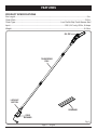
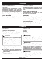
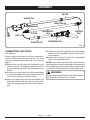
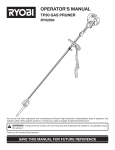
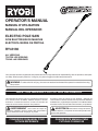
OPERATOR’S MANUAL MANUEL D’UTILISATION MANUAL DEL OPERADOR ELECTRIC POLE SAW SCIE ÉLECTRIQUE DE MANCHE ELÉCTRICA SIERRA DE PÉRTIGA RY43160 ALL VERSIONS TOUTES LES VERSIONS TODAS LAS VERSIONES Your pole saw has been engineered and manufactured to our high standard for dependability, ease of operation, and operator safety. When properly cared for, it will give you years of rugged, trouble-free performance. WARNING: To reduce the risk of injury, the user must read and understand the operator’s manual before using this product. SAVE THIS MANUAL FOR FUTURE REFERENCE Cette électrique de manche a été conçu et fabriqué conformément à nos strictes normes de fiabilité, simplicité d’emploi et sécurité d’utilisation. Correctement entretenu, cet outil vous donnera des années de fonctionnement robuste et sans problème. Su eléctrica sierra de pértiga ha sido diseñado y fabricado de conformidad con nuestras estrictas normas para brindar fiabilidad, facilidad de uso y seguridad para el operador. Con el debido cuidado, le brindará muchos años de sólido funcionamiento y sin problemas. AVERTISSEMENT : Pour réduire les risques de blessures, l’utilisateur doit lire et veiller à bien comprendre le manuel d’utilisation avant d’employer ce produit. ADVERTENCIA: Para reducir el riesgo de lesiones, el usuario debe leer y comprender el manual del operador antes de usar este producto. CONSERVER CE MANUEL POUR FUTURE RÉFÉRENCE GUARDE ESTE MANUAL PARA FUTURAS CONSULTAS TABLE OF CONTENTS TABLE DES MATIÈRES / ÍNDICE DE CONTENIDO Introduction........................................................................................................................................2 Introduction / Introducción Important Safety Instructions......................................................................................................... 3-4 Instructions importantes concernant la sécurité / Instrucciones de seguridad importantes Specific Safety Rules..................................................................................................................... 4-5 Règles de sécurité particulières / Reglas de seguridad específicas Symbols......................................................................................................................................... 6-7 Symboles / Símbolos Electrical.............................................................................................................................................8 Caractéristiques électriques / Aspectos eléctricos Features........................................................................................................................................ 9-10 Caractéristiques / Características Assembly.................................................................................................................................... 10-11 Assemblage / Armado Operation.................................................................................................................................... 12-15 Utilisation / Funcionamiento Maintenance............................................................................................................................... 16-20 Entretien / Mantenimiento Troubleshooting................................................................................................................................20 Dépannage / Corrección de problemas Warranty...........................................................................................................................................21 Garantie / Garantía Parts Ordering and Service................................................................................................ Back Page Commande de pièces et réparation / Pedidos de piezas y servicio.......................................................... Page arrière / Pág. posterior INTRODUCTION INTRODUCTION / INTRODUCCIÓN This product has many features for making its use more pleasant and enjoyable. Safety, performance, and dependability have been given top priority in the design of this product making it easy to maintain and operate. *** Ce produit offre de nombreuses fonctions destinées à rendre son utilisation plus plaisante et satisfaisante. Lors de la conception de ce produit, l’accent a été mis sur la sécurité, les performances et la fiabilité, afin d’en faire un outil facile à utiliser et à entretenir. *** Este producto ofrece numerosas características para hacer más agradable y placentero su uso. En el diseño de este producto se ha conferido prioridad a la seguridad, el desempeño y la fiabilidad, por lo cual se facilita su manejo y mantenimiento. Page 2 IMPORTANT SAFETY INSTRUCTIONS WARNING: Read and understand all instructions. Failure to follow all instructions listed below may result in electric shock, fire, and/or serious personal injury. READ ALL INSTRUCTIONS For safe operation, read and understand all instructions before using this product. Be familiar with all controls and proper use of the machine. Follow all safety instructions. Failure to follow all safety instructions listed below, can result in serious personal injury. Do not allow children or untrained individuals to use this unit. Thoroughly inspect the area where the equipment is to be used and remove all foreign objects. Wear eye protection with side shields, which is marked to comply with ANSI Z87.1, along with head protection when operating this equipment. Dress properly. Wear heavy long pants, long sleeves, boots, and gloves. Do not wear loose fitting clothing, short pants, sandals, or go barefoot. Do not wear jewelry of any kind. Secure long hair above shoulder level to prevent entanglement in moving parts. Keep all bystanders, children, and pets at least 50 ft. away. Stay Alert — Watch what you are doing; use common sense. Do not operate this unit when you are tired, ill, or under the influence of alcohol, drugs, or medication. Do not operate in poor lighting. Keep firm footing and balance. Do not overreach. Overreaching can result in loss of balance or exposure to hot surfaces. Keep all parts of your body away from any moving part. Inspect the unit before each use for loose fasteners, etc. Replace any damaged parts before use. When not in use, product should be stored indoors in a dry, locked up place—out of the reach of children. Use only original manufacturer’s replacement parts. Failure to do so may cause poor performance, possible injury, and will void your warranty. Do not, under any circumstance, use any attachment or accessory on this product which was not provided with the product or identified as appropriate for use with this product in the operator’s manual. Avoid dangerous environments. Do not use the product in damp or wet locations. Do not use in rain. Use the right appliance. Do not use the product for any job except that for which it is intended. Do not operate from steps, a ladder, rooftop, tree, or unstable support. Stable footing on a solid surface enables better control of the product in unexpected situations. Do not force the product. It will do the job better and with less likelihood of a risk of injury at the rate for which it was designed. DANGER — Keep hands away from cutting area. Keep both hands on handles when power is on. CAUTION — Blade coasts after being turned off. To reduce the risk of electric shock, this product has a polarized plug (one blade is wider than the other) and will require the use of a polarized extension cord. The plug will fit into a polarized extension cord only one way. If the plug does not fit fully into the extension cord, reverse the plug. If the plug still does not fit, obtain a correct polarized extension cord. A polarized extension cord will require the use of a polarized wall outlet. This plug will fit into the polarized wall outlet only one way. If the plug does not fit fully into the wall outlet, reverse the plug. If the plug still does not fit, contact a qualified electrician to install the proper wall outlet. Do not change the equipment plug, extension cord receptacle, or extension cord plug in any way. Do not abuse the cord. Never use the cord to carry the product or to disconnect the plug from an outlet. Keep cord away from heat, oil, sharp Page 3 — English IMPORTANT SAFETY INSTRUCTIONS edges, or moving parts. Replace damaged cords immediately. Damaged cords increase the risk of electric shock. Make sure your extension cord is in good condition. When using an extension cord, be sure to use one heavy enough to carry the current your product will draw. A wire gauge size (A.W.G.) of at least 16 is recommended for an extension cord 50 feet or less in length. If in doubt, use the next heavier gauge. The smaller the gauge number, the heavier the cord. An undersized cord will cause a drop in line voltage resulting in loss of power and overheating. WARNING: Use outdoor extension cords marked SW-A, SOW-A, STW-A, STOW-A, SJW-A, SJTWA, or SJTOW-A. These cords are rated for outdoor use and reduce the risk of electric shock. Ground Fault Circuit Interrupter (GFCI) protection should be provided on the circuit(s) or outlet(s) to be used for the product. Receptacles are available having built-in GFCI protection and may be used for this measure of safety. SPECIFIC SAFETY RULES Kickback is a dangerous reaction that can lead to serious injury. Kickback may occur when the moving chain contacts an object at the upper portion of the tip of the guide bar or when the wood closes in and pinches the chain in the cut. Contact at the upper portion of the tip of the guide bar can cause the chain to dig into the object and stop the chain for an instant. The result is a lightning-fast, reverse reaction which kicks the guide bar up and back toward the operator. If the chain is pinched along the top of the guide bar, the guide bar can be driven rapidly back toward the operator, which can cause loss of control and may result in serious injury. Do not rely exclusively upon the safety devices built into the product. With a basic understanding of kickback, you can reduce or eliminate the element of surprise. Sudden surprise contributes to accidents. Use pole saw for cutting wood only. Do not use for cutting non-wood items. Make sure that the area in which you are cutting is free from obstructions. Do not let the nose of the guide bar contact a log, branch, fence, or any other obstruction while you are operating the unit. Have a planned retreat path. Do not grasp the exposed cutting blades or cutting edges when picking up or holding the product. Cut only when visibility and light are adequate for you to see clearly. To protect yourself from electrocution, do not operate within 50 feet of overhead electrical lines. Before starting the motor, make sure the chain is not contacting any object. To protect yourself from falling branches, do not stand directly under the branch or limb being cut. This unit should not be held at an angle over 60° from ground level. Turn off the motor and make sure cutting attachment has stopped before setting unit down. Follow the sharpening and maintenance instructions for the saw chain. Use only the replacement guide bars and low kickback chains specified for the unit. Do not operate the saw with one hand! Serious injury to the operator, helpers, bystanders, or any combination of these persons may results from one hand operation. This saw intended for two-handed use. Use extreme caution when cutting small-sized brush and saplings because slender material may catch the saw chain and be whipped toward you or pull you off balance. When cutting a limb that is under tension, be alert for spring back so that you will not be struck when the tension in the wood fibers is released. To avoid accidental starting, never carry plugged in product with finger on switch. Be sure switch is off when plugging in. Page 4 — English SPECIFIC SAFETY SAFETY RULES RULES SPECIFIC Maintain product with care. Keep cutting edge sharp and clean for best performance and to reduce the risk of injury. Follow instructions for lubricating and changing accessories. Inspect cord periodically and, if damaged, have it repaired by an authorized service facility. Inspect extension cords periodically and replace if damaged. Keep handles dry, clean, and free from oil and grease. Check damaged parts. Before further use of the product, a guard or other part that is damaged should be carefully checked to determine that it will operate properly and perform its intended function. Check for alignment of moving parts, binding of moving parts, breakage of parts, mounting, and any other condition that may affect its operation. A guard or other part that is damaged should be properly repaired or replaced by an authorized service center unless indicated elsewhere in this manual. Disconnect the plug from power source when not in use, before servicing, and when changing accessories. Service on the product must be performed by qualified repair personnel only. Service or maintenance performed by unqualified personnel could result in injury to the user or damage to the product. If the power supply cord is damaged, it must be replaced only by the manufacturer or by an authorized service center to avoid risk. Save these instructions. Refer to them frequently and use them to instruct others who may use this product. If you loan someone this product, loan them these instructions also to prevent misuse of the product and possible injury. Page 5 — English SYMBOLS Some of the following symbols may be used on this product. Please study them and learn their meaning. Proper interpretation of these symbols will allow you to operate the product better and safer. SYMBOL NAME EXPLANATION Safety Alert Symbol Indicates a potential personal injury hazard. To reduce the risk of injury, user must read and understand operator’s manual before using this product. Always wear eye protection with side shields marked to comply with ANSI Z87.1, along with head protection. Read the Operator’s Manual Wear Eye and Head Protection Wet Conditions Alert Do not expose to rain or use in damp locations. Keep Bystanders Away Keep all bystanders at least 50 ft. away. Gloves Wear non-slip, heavy-duty protective gloves when handling the pole saw and the blade. Safety Footwear Wear non-slip safety footwear when using this equipment. Keep Tool Away from Electrical Lines/Keep Bystanders Away DANGER! Risk of electrocution! Keep tool 50 feet away from electrical lines. Keep all bystanders at least 50 ft. away. Electric Shock Failure to use in dry conditions and to observe safe practices can result in electric shock. No Hands Symbol Failure to keep your hands away from the blade will result in serious personal injury. V Volts Voltage A Amperes Current Hz Hertz Frequency (cycles per second) W Watt Power hrs Hours Time no No Load Speed Rotational speed, at no load Class II Construction Double-insulated construction Per Minute Revolutions, strokes, surface speed, orbits etc., per minute .../min Page 6 — English SYMBOLS The following signal words and meanings are intended to explain the levels of risk associated with this product. SYMBOL SIGNAL MEANING DANGER: Indicates an imminently hazardous situation, which, if not avoided, will result in death or serious injury. WARNING: Indicates a potentially hazardous situation, which, if not avoided, could result in death or serious injury. CAUTION: Indicates a potentially hazardous situation, which, if not avoided, may result in minor or moderate injury. CAUTION: (Without Safety Alert Symbol) Indicates a situation that may result in property damage. Page 7 — English ELECTRICAL DOUBLE INSULATION Double insulation is a concept in safety in electric power tools, which eliminates the need for the usual three-wire grounded power cord. All exposed metal parts are isolated from the internal metal motor components with protecting insulation. Double insulated tools do not need to be grounded. It is possible to tie the extension cord and power cord in a knot to prevent them from becoming disconnected during use. Make the knot as shown in figure 1, then connect the plug end of the power cord into the receptacle end of the extension cord. This method can also be used to tie two extension cords together. WARNING: The double insulated system is intended to protect the user from shock resulting from a break in the tool’s internal insulation. Observe all normal safety precautions to avoid electrical shock. NOTE: Servicing of a product with double insulation requires extreme care and knowledge of the system and should be performed only by a qualified service technician. For service, we suggest you return the product to your nearest authorized service center for repair. Always use original factory replacement parts when servicing. Fig. 1 **Ampere rating (on product data plate) 0-2.0 2.1-3.4 3.5-5.0 5.1-7.0 7.1-12.0 12.1-16.0 Cord LengthWire Size (A.W.G.) ELECTRICAL CONNECTION 25'16 16161614 14 This product has a precision-built electric motor. It should be connected to a power supply that is 120 volts, AC only (normal household current), 60 Hz. Do not operate this product on direct current (DC). A substantial voltage drop will cause a loss of power and the motor will overheat. If the product does not operate when plugged into an outlet, double-check the power supply. 50'16 16161414 12 EXTENSION CORDS See Figure 1. When using a power tool at a considerable distance from a power source, be sure to use an extension cord that has the capacity to handle the current the product will draw. An undersized cord will cause a drop in line voltage, resulting in overheating and loss of power. Use the chart to determine the minimum wire size required in an extension cord. Only round jacketed cords listed by Underwriter’s Laboratories (UL) should be used. When working outdoors with a product, use an extension cord that is designed for outside use. This type of cord is designated with “W-A” or “W” on the cord’s jacket. Before using any extension cord, inspect it for loose or exposed wires and cut or worn insulation. A proper extension cord is available at an authorized service center. 100'16 16141210 — **Used on 12 gauge - 20 amp circuit. NOTE: AWG = American Wire Gauge WARNING: Keep the extension cord clear of the working area. Position the cord so that it will not get caught on lumber, tools, or other obstructions while you are working with a power tool. Failure to do so can result in serious personal injury. WARNING: Check extension cords before each use. If damaged replace immediately. Never use the product with a damaged cord since touching the damaged area could cause electrical shock resulting in serious injury. Page 8 — English FEATURES PRODUCT SPECIFICATIONS Bar Length........................................................................................................................................ 8 in. Chain Pitch.....................................................................................................................................3/8 in. Chain Type....................................................................................... Low Profile Skip Tooth Narrow Kerf Input........................................................................................................120 V, AC only, 60 Hz, 6 Amps Weight..........................................................................................................................................8.5 lbs. OIL CAP TELESCOPING POLE LOCK-OUT BUTTON SCABBARD CORD RETAINER Fig. 2 Page 9 — English FEATURES KNOW YOUR POLE SAW See Figure 2. The safe use of this product requires an understanding of the information on the product and in this operator’s manual as well as a knowledge of the project you are attempting. Before use of this product, familiarize yourself with all operating features and safety rules. LOCK-OUT BUTTON To help prevent accidental starting, the lock-out button must be depressed along with the switch trigger. QUICK-VIEW OIL INDICATOR Semi-transparent bar lube reservoir that allows user to see when to add lubricant. CORD RETAINER SCABBARD A convenient cord retainer helps keep the extension cord connection secure during tool operation. The scabbard keeps the operator from coming in contact with the sharp blades when the tool is not in use. It also helps keep the blades from being nicked or damaged when the tool is in storage. TELESCOPING POLE The pole can be adjusted to different lengths for ease of use. ASSEMBLY UNPACKING PACKING LIST This product requires assembly. nCarefully remove the product and any accessories from the box. Make sure that all items listed in the packing list are included. Pole Saw Scabbard Operator’s Manual WARNING: WARNING: Do not use this product if any parts on the Packing List are already assembled to your product when you unpack it. Parts on this list are not assembled to the product by the manufacturer and require customer installation. Use of a product that may have been improperly assembled could result in serious personal injury. nInspect the product carefully to make sure no breakage or damage occurred during shipping. nDo not discard the packing material until you have carefully inspected and satisfactorily operated the product. n If any parts are damaged or missing, please call 1-800-860-4050 for assistance. If any parts are damaged or missing, do not operate this product until the parts are replaced. Use of this product with damaged or missing parts could result in serious personal injury. WARNING: Do not attempt to modify this product or create accessories not recommended for use with this product. Any such alteration or modification is misuse and could result in a hazardous condition leading to possible serious personal injury. WARNING: Do not connect to power supply until assembly is complete. Failure to comply could result in accidental starting and possible serious personal injury. Page 10 — English ASSEMBLY BUTTON HANDLE POLE LOWER COLLAR THREADED BASE CORD INTERMEDIATE POLE BUTTON UPPER COLLAR THREADED BASE POWERHEAD POLE Fig. 3 CONNECTING THE POLES See Figure 3. Before using the pole saw, a one-time assembly is required. When removed from the box, the three poles are connected by an electrical cord as shown above. nRemove the four (4) rubber cord protectors from inside the poles. This material protects the cord during shipping and MUST be discarded immediately. n Unscrew the lower collar from the threaded base on the intermediate pole and push back over the cord to the handle pole shaft as shown. nInsert the handle pole into the intermediate pole and slide together until you hear the button click. The tubes are egg-shaped and will only install one way. n Lower the collar on the handle pole to the threaded base on the intermediate pole and rotate clockwise to secure. nRepeat this process to attach the intermediate pole to the powerhead pole. NOTE: Once assembled correctly, handle pole and powerhead pole should not be able to separate from intermediate pole when pulled. Repeat above steps if poles can be separated from intermediate pole. WARNING: Failure to lock powerhead pole as directed above could result in serious injury or death. Page 11 — English OPERATION ADDING BAR AND CHAIN LUBRICANT DANGER: Never cut near power lines, electric cords, or other electric sources. If bar and chain jams on any electrical cord or line, DO NOT TOUCH THE BAR OR CHAIN, THEY CAN BECOME ELECTRICALLY LIVE AND VERY DANGEROUS! Continue to hold the pole saw by the insulated rear handle or lay it down and away from you in a safe manner. Disconnect the electrical service to the damaged line or cord before attempting to free the bar and chain from the line or cord. Contact with the bar, chain, other conductive parts of the pole saw, or live electric cords or lines will result in death by electrocution or serious injury. WARNING: Do not allow familiarity with this product to make you careless. Remember that a careless fraction of a second is sufficient to inflict serious injury. WARNING: Always wear eye protection with side shields marked to comply with ANSI Z87.1, along with head protection. Failure to do so could result in objects being thrown into your eyes and other possible serious injuries. See Figure 4 Use Bar and Chain Lubricant. It is designed for chains and chain oilers, and is formulated to perform over a wide temperature range with no dilution required. NOTE: Pole saw comes from the factory with no bar and chain oil added. Level should also be checked after every 20 minutes of use and refilled as needed. n Remove oil cap. n Carefully pour the bar and chain oil into the tank. n Wipe off excess oil. n Check and fill the oil tank when quick view oil indicator is below the second to last indicator line. n Repeat as needed. NOTE: Do not use dirty, used or otherwise contaminated oils. Damage may occur to the bar or chain. NOTE: It is normal for oil to seep from the saw when not in use. To prevent seepage, empty the oil tank after each use then run for one minute. When storing the unit for a long period of time (three months or longer) be sure the chain is lightly lubricated; this will prevent rust on the chain and bar sprocket. WARNING: CHAIN T LUBRICAN Do not use any attachments or accessories not recommended by the manufacturer of this product. The use of attachments or accessories not recommended can result in serious personal injury. OIL RESERVOIR CAP APPLICATIONS You may use this product for the purposes listed below: nLimbing nPruning QUICK VIEW OIL INDICATOR Fig. 4 Page 12 — English OPERATION CONNECTING TO POWER SUPPLY See Figure 5. This product is designed with a cord retainer that prevents the extension cord from being pulled loose while using. n Form a loop with the end of the extension cord. n Insert loop portion of extension cord through opening in the bottom of the rear handle and place over cord retainer. n Slowly pull loop against cord retainer until the slack is removed. n Plug product into extension cord. NOTE: Failure to remove all excess cord slack from extension cord retainer could result in plug loosening from receptacle. STARTING AND STOPPING See Figure 5. To start the motor: nConnect the pole saw to power supply. nPlace your thumb on the lock-out button and pull it completely towards you. nFully depress the switch trigger. To stop the motor: nRelease the switch trigger. LOCK-OUT BUTTON SWITCH TRIGGER CORD RETAINER Fig. 5 ADJUSTING TELESCOPING POLE See Figure 6. nDisconnect the pole saw from the power supply. nRotate the collar counterclockwise to loosen. nPush poles towards each other to shorten the pole or pull away from each other to lengthen the pole. NOTE: Extend the pole only to the length required to reach the limb being cut. Do not extend the handle above waist height. n When the desired length is achieved, rotate the collar clockwise to secure. NOTE: Adjust hand placement on the shaft of the pole saw to keep proper balance. Do not attempt to use the pole saw at a length which does not allow you to achieve proper footing and balance at all times. Page 13 — English OPERATION PREPARATION FOR CUTTING See Figures 7 - 8. nWear non-slip gloves for maximum grip and protection. n Maintain a proper grip on the unit whenever the motor is running. Use your right hand to firmly grip the rear handle while your left hand has a firm grip on the pole shaft. nHold unit firmly with both hands. Always keep your left hand on the pole shaft and your right hand on the rear handle, so your body is to the left of the chain line. Never use a left-handed (cross-handed) grip, or any stance that places your body or arm across the chain line. n Never stand directly under the limb you are cutting. nBe certain the collars are fully tightened before operating equipment; check them periodically for tightness during use to avoid serious injury. BASIC CUTTING PROCEDURE Follow the steps below to prevent damage to tree or shrub bark. Do not use a back-and-forth sawing motion. nMake a shallow first cut (1/4 of limb diameter) on the underside of the limb close to the main limb or trunk. n Make a second cut from the top side of the limb outboard from the first cut. Continue the cut through the limb until the limb separates from the tree. Be prepared to balance the weight of the tool when the limb falls. nMake a final cut close to trunk. N OTE: For second and final cuts (from top of limb or branch), hold front cutting guide against the limb being cut. This will help steady the limb and make it easier to cut. Allow chain to cut for you; exert only light downward pressure. If you force the cut, damage to the bar, chain, or motor can result. nRelease the trigger as soon as the cut is completed. COLLAR Fig. 6 LOAD SECOND CUT FIRST CUT 1/4 DIAMETER FINAL CUT Fig. 7 CUTTING GUIDE Fig. 8 Failure to follow proper cutting procedures will result in the bar and chain binding and becoming pinched or trapped in the limb. If this should happen: nStop the motor and disconnect from power supply. nIf the limb can be reached from the ground, lift the limb while holding the saw. This should release the “pinch” and free the saw. nIf the saw is still trapped, call a professional for assistance. Page 14 — English OPERATION LIMBING AND PRUNING See Figures 9 - 10. This unit is designed for trimming small branches and limbs up to 6 in. in diameter. For best results, observe the following precautions. n Plan the cut carefully. Be aware of the direction in which the branch will fall. n Branches may fall in unexpected directions. Do not stand directly under the branch being cut. nThe most typical cutting application is to position the unit at an angle of 60° or less, depending on the specific situation, as shown. As the angle of the pole saw shaft to ground increases, the difficulty of making the first cut (from the underside of limb) increases. nRemove long branches in several stages. n Cut lower branches first to allow the top branches more room to fall. nWork slowly, keeping both hands on the saw with a firm grip. Maintain secure footing and balance. nKeep the tree between you and the chain while limbing. Cut from side of tree opposite branch you are cutting. nDo not cut from a ladder; this is extremely dangerous. Leave this operation for professionals. n Do not make the flush cut next to the main limb or trunk until you have cut off the limb further out to reduce the weight. Following proper cutting procedures will prevent stripping the bark from the main member. nDo not use the pole saw for felling or bucking. n To prevent electrocution, do not operate within 50 ft. of overhead electrical lines. nKeep bystanders at least 50 ft. away. Page 15 — English 60° MAXIMUM Fig. 9 Fig. 10 MAINTENANCE WARNING: FLATS When servicing, use only identical replacement parts. Use of any other parts could create a hazard or cause product damage. WARNING: Fig. 11 Always wear eye protection with side shields marked to comply with ANSI Z87.1, along with head protection. Failure to do so could result in objects being thrown into your eyes and other possible serious injuries. WARNING: Before inspecting, cleaning or servicing the unit, stop the motor, wait for all moving parts to stop, and disconnect from power supply. Failure to follow these instructions can result in serious personal injury or property damage. GENERAL MAINTENANCE Avoid using solvents when cleaning plastic parts. Most plastics are susceptible to damage from various types of commercial solvents and may be damaged by their use. Use clean cloths to remove dirt, dust, oil, grease, etc. WARNING: Do not at any time let brake fluids, gasoline, petroleum-based products, penetrating oils, etc., come in contact with plastic parts. Chemicals can damage, weaken, or destroy plastic, which could result in serious personal injury. All chain saw service, other than the items listed in the instruction manual maintenance instructions, should be performed by competent chain saw service personnel. (For example, if improper tool is used to hold the flywheel in order to remove the clutch, structural damage to the flywheel could occur and subsequently could cause the flywheel to burst). APPROX .050 in. Fig. 12 CHAIN TENSION See Figures 11 - 12. WARNING: To avoid possible serious injury, never touch or adjust the chain while the motor is running. The saw chain is very sharp; always wear protective gloves when performing maintenance to the chain. nStop the motor and disconnect from power supply before setting the chain tension. Make sure the guide bar nut is loose to finger tight, turn the chain tensioning screw clockwise to tension the chain. Refer to Replacing the Bar and Chain for additional information. NOTE: A cold chain is correctly tensioned when there is no slack on the underside of the guide bar, the chain is snug, but it can be turned by hand without binding. nChain must be re-tensioned whenever the flats on the drive links hang out of the bar groove as shown in fig. 11. nDuring normal operation, the temperature of the chain will increase. The drive links of a correctly tensioned warm chain will hang approximately .050 in. out of the bar groove, as shown in fig. 12. Page 16 — English MAINTENANCE NOTE: New chain tends to stretch; check chain tension frequently and tension as required. DRIVECASE COVER CHAIN BAR CAUTION: Chain tensioned while warm, can be too tight upon cooling. Check the “cold tension” before next use. BAR NUT REPLACING THE BAR AND CHAIN SPROCKET See Figures 13 - 16. Fig. 13 CHAIN TENSIONING PIN WARNING: To avoid possible serious injury, stop the motor and disconnect from power supply before replacing the bar, chain, or performing any maintenance operation. nRemove the bar nut (7/16 in.) and drivecase cover. n The bar contains a bar stud slot that fits over the bar stud. The bar also contains a chain tensioning pin hole which fits over the chain tensioning pin. nPlace the bar onto the bar stud so that the chain tensioning pin fits into the chain tensioning pin hole. nFit the chain over the sprocket and into the bar groove. The cutters on the top of the bar should face toward the bar tip, in the direction of the chain rotation. nReplace the drivecase cover and install the bar nut. Tighten the bar nut finger tight only. The bar must be free to move for tension adjustment. nRemove all slack from chain by turning the chain tensioning screw clockwise, assuring that the chain seats into the bar groove during tensioning. nLift the tip of the bar up to check for sag. Release the tip of the bar, and turn the chain tensioning screw 1/2 turn clockwise. Repeat this process until sag does not exist. nHold the tip of the bar up and tighten the bar nut securely. nChain is correctly tensioned when there is no slack on the underside of the bar, the chain is snug, but it can be turned by hand without binding. DRIVECASE COVER BAR STUD BAR BAR NUT CHAIN TENSIONING PIN HOLE BAR STUD SLOT Fig. 14 CHAIN ROTATION SPROCKET CHAIN CHAIN TENSIONING SCREW Fig. 15 NOTE: If chain is too tight, it will not rotate. Loosen the bar nut slightly and turn adjusting screw 1/4 turn counterclockwise. Lift the tip of the bar up and retighten bar nut. Page 17 — English MAINTENANCE CHAIN OILER See Figure 17. nUse Premium Bar and Chain Lubricant. It is designed for chains and chain oilers and is formulated to perform over a wide temperature range with no dilution required. nRemove the cap and carefully pour approximately 2 oz. of bar and chain lubricant into the bar lube reservoir. nReplace the cap and tighten securely. nCheck and refill the bar lube reservoir every time the pole saw is used. NOTE: Do not use dirty, used, or otherwise contaminated lubricants. Damage may occur to the oil pump, bar, or chain. BAR NUT CHAIN MAINTENANCE See Figure 18. For smooth and fast cutting, the chain needs to be maintained properly. The following conditions indicate that the chain requires sharpening: n Wood chips are small and powdery n Chain must be forced through the wood during cutting n Chain cuts to one side During maintenance of the chain, consider the following: n Improper filing angle of the side plate can increase the risk of a severe kickback. n Depth gauge (or raker clearance) setting determines the height the cutter enters the wood and the size of the wood chip that is removed. Too much clearance increases the potential for kickback. Too little clearance decreases the size of the wood chip thus decreasing the chain's cutting ability. n If cutter teeth have hit hard objects such as nails and stones, or have been abraded by mud or sand on the wood, have service dealer sharpen chain. Fig. 16 REMOVE CAP BAR LUBE RESERVOIR Fig. 17 RAKER (DEPTH GAUGE) CLEARANCE Page 18 — English .025 in. Fig. 18 MAINTENANCE HOW TO SHARPEN THE CUTTERS See Figures 19 - 22. Be careful to file all cutters to the specified angles and to the same length, as fast cutting can be obtained only when all cutters are uniform. n Tighten the chain tension enough that the chain does not wobble. Do all of your filing at the midpoint of the bar. Wear gloves for protection. n Use a 5/32 in. diameter round file and holder. n Keep the file level with the top plate of the tooth. Do not let the file dip or rock. n Using light but firm pressure, stroke towards the front corner of the tooth. Lift file away from the steel on each return stroke. n Put a few firm strokes on every tooth. File all left hand cutters in one direction. Then move to the other side and file the right hand cutters in the opposite direction. Occasionally remove filings from the file with a wire brush. PARTS OF A CUTTER CUTTING CORNER TOP PLATE SIDE PLATE DEPTH GAUGE RIVET HOLE HEEL GULLET TOE Fig. 19 Fig. 20 CAUTION: Dull or improperly sharpened chain can cause excessive motor speed during cutting which may result in severe motor damage. WARNING: Improper chain sharpening increases the potential of kickback. Failure to replace or repair damaged chain can cause serious injury. Fig. 21 LEFT HAND CUTTERS RIGHT HAND CUTTERS Fig. 22 Page 19 — English MAINTENANCE STORING THE PRODUCT See Figure 23. Clean all foreign material from the product. Store idle unit indoors in a dry, well-ventilated area that is inaccessible to children. Keep away from corrosive agents such as garden chemicals and de-icing salts. nAlways place the scabbard on the saw bar when transporting or storing the pole saw. The scabbard is a snug fit and must be attached very carefully due to the sharp teeth on the saw chain. This is best done by grasping the scabbard at one end, in the center portion of the scabbard, and carefully sliding it over the chain as shown. Use caution to avoid the sharp teeth of the chain. SCABBARD Fig. 23 NOTE: The saw chain is very sharp. Always wear protective gloves when handling the chain. TROUBLESHOOTING PROBLEM CAUSE REMEDY B a r a n d c h a i n Check chain tension running hot and f o r o v e r t i g h t e n e d smoking. condition B a r l u b e re s e r v o i r empty Tension chain. Refer to Chain Tension earlier in this manual. M o t o r r u n s , Chain tension too but chain is not tight. rotating. Check guide bar and chain assembly. Check guide bar and chain for damage. Retention chain. Refer to Chain Tension earlier in this manual. Refer to Replacing the Bar and Chain earlier in this manual. Inspect guide bar and chain for damage. Check bar lube reservoir. CALL US FIRST For any questions about operating or maintaining your product, call the Ryobi® Help Line! Your product has been fully tested prior to shipment to ensure your complete satisfaction. Page 20 — English WARRANTY LIMITED WARRANTY STATEMENT Techtronic Industries North America, Inc., warrants to the original retail purchaser that this RYOBI® brand outdoor product is free from defect in material and workmanship and agrees to repair or replace, at Techtronic Industries North America, Inc.’s, discretion, any defective product free of charge within these time periods from the date of purchase. Three years if the product is used for personal, family or household use; 90 days, if used for any other purpose, such as commercial or rental. This warranty extends to the original retail purchaser only and commences on the date of the original retail purchase. Any part of this product found in the reasonable judgment of Techtronic Industries North America, Inc. to be defective in material or workmanship will be repaired or replaced without charge for parts and labor by an authorized service center for RYOBI® brand outdoor products (Authorized Ryobi Service Center). The product, including any defective part, must be returned to an authorized Ryobi service center within the warranty period. The expense of delivering the product to the service center for warranty work and the expense of returning it back to the owner after repair or replacement will be paid by the owner. Techtronic Industries North America, Inc.’s, responsibility in respect to claims is limited to making the required repairs or replacements and no claim of breach of warranty shall be cause for cancellation or rescission of the contract of sale of any RYOBI® brand outdoor product. Proof of purchase will be required by the dealer to substantiate any warranty claim. All warranty work must be performed by an authorized service dealer. This warranty is limited to ninety (90) days from the date of original retail purchase for any RYOBI® brand outdoor product that is used for rental or commercial purposes, or any other income-producing purpose. This warranty does not cover any product that has been subject to misuse, neglect, negligence, or accident, or that has been operated in any way contrary to the operating instructions as specified in this operator’s manual. This warranty does not apply to any damage to the product that is the result of improper maintenance or to any product that has been altered or modified. The warranty does not extend to repairs made necessary by normal wear or by the use of parts or accessories which are either incompatible with the RYOBI® brand outdoor product or adversely affect its operation, performance, or durability. In addition, this warranty does not cover: A.Tune-ups – Spark Plugs, Carburetor, Carburetor Adjustments, Ignition, Filters B. Wear items – Bump Knobs, Outer Spools, Cutting Lines, Inner Reels, Starter Pulleys, Starter Ropes, Drive Belts, Tines, Felt Washers, Hitch Pins, Mulching Blades, Blower Fans, Blower and Vacuum Tubes, Vacuum Bag and Straps, Guide Bars, Saw Chains Techtronic Industries North America, Inc., reserves the right to change or improve the design of any RYOBI® brand outdoor product without assuming any obligation to modify any product previously manufactured. ALL IMPLIED WARRANTIES ARE LIMITED IN DURATION TO THE STATED WARRANTY PERIOD. ACCORDINGLY, ANY SUCH IMPLIED WARRANTIES INCLUDING MERCHANTABILITY, FITNESS FOR A PARTICULAR PURPOSE, OR OTHERWISE, ARE DISCLAIMED IN THEIR ENTIRETY AFTER THE EXPIRATION OF THE APPROPRIATE THREE-YEAR OR NINETY-DAY WARRANTY PERIOD. TECHTRONIC INDUSTRIES NORTH AMERICA, INC.’S, OBLIGATION UNDER THIS WARRANTY IS STRICTLY AND EXCLUSIVELY LIMITED TO THE REPAIR OR REPLACEMENT OF DEFECTIVE PARTS AND TECHTRONIC INDUSTRIES NORTH AMERICA, INC., DOES NOT ASSUME OR AUTHORIZE ANYONE TO ASSUME FOR THEM ANY OTHER OBLIGATION. SOME STATES DO NOT ALLOW LIMITATIONS ON HOW LONG AN IMPLIED WARRANTY LASTS, SO THE ABOVE LIMITATION MAY NOT APPLY TO YOU. TECHTRONIC INDUSTRIES NORTH AMERICA, INC., ASSUMES NO RESPONSIBILITY FOR INCIDENTAL, CONSEQUENTIAL, OR OTHER DAMAGES INCLUDING, BUT NOT LIMITED TO, EXPENSE OF RETURNING THE PRODUCT TO AN AUTHORIZED RYOBI SERVICE CENTER AND EXPENSE OF DELIVERING IT BACK TO THE OWNER, MECHANIC’S TRAVEL TIME, TELEPHONE OR TELEGRAM CHARGES, RENTAL OF A LIKE PRODUCT DURING THE TIME WARRANTY SERVICE IS BEING PERFORMED, TRAVEL, LOSS OR DAMAGE TO PERSONAL PROPERTY, LOSS OF REVENUE, LOSS OF USE OF THE PRODUCT, LOSS OF TIME, OR INCONVENIENCE. SOME STATES DO NOT ALLOW THE EXCLUSION OR LIMITATION OF INCIDENTAL OR CONSEQUENTIAL DAMAGES, SO THE ABOVE LIMITATION OR EXCLUSION MAY NOT APPLY TO YOU. This warranty gives you specific legal rights, and you may also have other rights which vary from state to state. This warranty applies to all RYOBI® brand outdoor products manufactured by or for Techtronic Industries North America, Inc., and sold in the United States and Canada. To locate your nearest Authorized Ryobi Service Center, dial 1-800-860-4050. Page 21 — English OPERATOR’S MANUAL / ELECTRIC POLE SAW MANUEL D’UTILISATION / SCIE ÉLECTRIQUE DE MANCHE MANUAL DEL OPERADOR / ELÉCTRICA SIERRA DE PÉRTIGA RY43160 WARNING: This product and substances that may become airborne from its use may contain chemicals, including lead, known to the State of California to cause cancer, birth defects, or other reproductive harm. Wash hands after handling. CALIFORNIA PROPOSITION 65 AVERTISSEMENT : Ce produit ainsi que les substances rejetées dans l’air à la suite de son utilisation peuvent contenir des produits chimiques, notamment du plomb qui, selon l’État de la Californie, peuvent causer le cancer, des anomalies congénitales et d’autres dommages au système reproducteur. Bien se laver les mains après toute manipulation. PROPOSITION 65 DE L’ÉTAT DE CALIFORNIE ADVERTENCIA: Este producto y sustancias que puedan llegar a ser aerotransportadas por su uso pueden contener sustancias químicas (por ejemplo, plomo) consideradas por el estado de California como causantes de cáncer, defectos de nacimiento u otras alteraciones reproductivas. Lávese las manos después de utilizar el aparato. CALIFORNIA - PROPUESTA DE LEY NÚM. 65 RYOBI is a registered trademark of Ryobi Limited and is used pursuant to a license granted by Ryobi Limited. RYOBI est une marque déposée de RYOBI Limited et est utilisée en vertu d’une licence accordée par Ryobi Limited. RYOBI es una marca registrada de Ryobi Limited y se utiliza conforme a una licencia otorgada por Ryobi Limited. • PARTS AND SERVICE Prior to requesting service or purchasing replacement parts, please obtain your model and serial number from the product data plate. RY43160 • MODEL NO._______________________SERIAL NO.___________________________ • HOW TO OBTAIN REPLACEMENT PARTS: Replacement parts can be purchased online at www.ryobitools.com or by calling 1-800-860-4050. Replacement parts can also be obtained at one of our Authorized Service Centers. • HOW TO LOCATE AN AUTHORIZED SERVICE CENTER: Authorized Service Centers can be located online at www.ryobitools.com or by calling 1-800-860-4050. • HOW TO OBTAIN CUSTOMER OR TECHNICAL SUPPORT: To obtain Customer or Technical Support please contact us at 1-800-860-4050. • PIÈCES ET SERVICE Avant de faire la demande de service ou l’achat de pièces de remplacement, veuillez obtenir le numéro de série du modèle à partir de la plaque de données du produit. RY43160 • NUMÉRO DE MODÈLE_____________NUMÉRO DE SÉRIE____________________ • COMMENT OBTENIR LES PIÈCES DE REMPLACEMENT : Les pièces de remplacement peuvent être achetées en ligne sur le site www.ryobitools.com ou par téléphone au 1-800-860-4050. Les pièces de remplacement peuvent être obtenues à un de nos centres de service autorisés. • COMMENT TROUVER UN CENTRE DE SERVICE AUTORISÉ : Les centres de service autorisés peuvent être localisés en ligne au www.ryobitools. com ou en téléphonant au 1-800-860-4050. • COMMENT OBTENIR DE L’AIDE EN CONTACTANT LE SERVICE À LA CLIENTÈLE : Pour contacter le service à la clientèle pour une question technique ou pour tout autre renseignement, veuillez nous téléphoner au 1-800-860-4050. • PIEZAS DE REPUESTO Y SERVICIO Antes de solicitar servicio técnico o comprar piezas de repuesto, obtenga su modelo y número de serie de la placa de datos del producto. • NÚMERO DE MODELO_____________NÚMERO DE SERIE____________________ RY43160 • CÓMO OBTENER PIEZAS DE REPUESTO: Las piezas de repuesto se pueden comprar en nuestro sitio en la red mundial, en la dirección www.ryobitools.com o llamando al 1-800-860-4050. Las piezas de repuesto también se pueden obtener en uno de nuestros Centros de Servicio Autorizados. • CÓMO LOCALIZAR UN CENTRO DE SERVICIO AUTORIZADO: Puede encontrar los Centros de Servicio Autorizados visitando nuestro sitio en la red mundial, en la dirección www.ryobitools.com or by calling 1-800-860-4050. • CÓMO OBTENER SERVICIO O ASISTENCIA TÉCNICA AL CONSUMIDOR: Para obtener Servicio o Asistencia Técnica al Consumidor, sírvase comunicarse con nosotros llamando al 1-800-860-4050. TECHTRONIC INDUSTRIES NORTH AMERICA, INC. 1428 Pearman Dairy Road, Anderson, SC 29625 USA 1-800-860-4050 • www.ryobitools.com 988000-750 10-1-11 (REV:01)