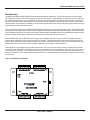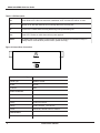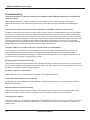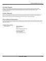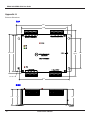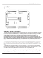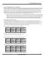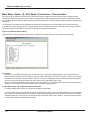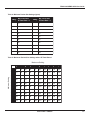
1
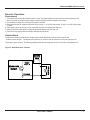
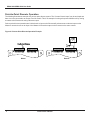
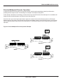
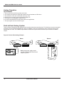
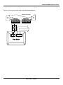
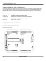
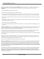
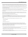
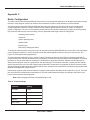
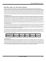
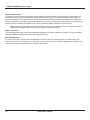
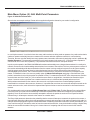
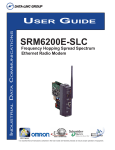
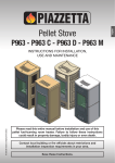
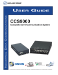
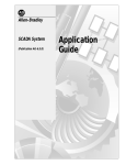
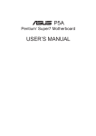
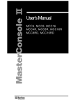
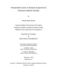
INDUSTRIAL DATA COMMUNICATIONS USER GUIDE DDAA1000/SRM/2.4 GHz Discrete/Analog Wireless Multiplexer It is essential that all instructions contained in the User Guide are followed precisely to ensure proper operation of equipment. Product User Guide FCC Notification This device complies with part 15 of the FCC rules. Operation is subject to the following conditions: 1) This device may not cause harmful interference and 2) This device must accept any interference received, including interference that may cause undesired operation. The device must be operated as supplied by Data-Linc Group. Any changes or modifications made to the device without the express written approval of Data-Linc Group may void the user’s authority to operate the device. Caution: This radio transmitter module has maximum transmitted output power of 500 mW. It is recommended that the transmit antenna be kept at least 23 cm away from nearby persons to satisfy FCC RF exposure requirements. Note: This equipment has been tested and found to comply with the limits for a Class A digital device, pursuant to part 15 of the FCC Rules. These limits are designed to provide reasonable protection against harmful interference in an industrial installation. This equipment generates, uses and can radiate radio frequency energy and, if not installed and used in accordance with the instructions, may cause harmful interference to radio communications. However, there is no guarantee that interference will not occur in a particular installation. If this equipment does cause harmful interference to radio or television reception, which can be determined by turning the equipment off and on, the user is encouraged to try to correct the interference by one or more of the following measures: Reorient or relocate the receiving antenna. Increase the separation between the equipment and receiver. Connect the equipment into an outlet on a circuit different from that to which the receiver is connected. Consult the dealer or an experienced radio/TV technician for help. Note: Whenever any Data-Linc Group series modem is placed inside an enclosure, a label must be placed on the outside of that enclosure which includes the modem’s FCC ID. The following types of antennas are approved for use with Data-Linc Group’s series modems. Consult Data-Linc Group Sales for particular model numbers. Only Data-Linc Group approved antennas can be legally used with this Data-Linc Group equipment. Antennas are available both as individual items or as part of a pre-made kit that includes cables. 2.4GHz Omni Directional Antenna 5dB Gain 2.4GHz Directional Antenna 6.6dB Gain 0dB Gain Note: The antenna used for this device must be professionally installed on a fixed-mounted permanent outdoor structure for satisfying RF exposure requirements, including antenna co-location requirements of 1.1307(b)(3). DATA-LINC GROUP PN 161-09981-002C DDAA1000/SRM/2.4GHz User Guide Table of Contents Page Introduction Discrete Operation Analog Operation Changing System or Radio Configurations ○ ○ ○ ○ ○ ○ ○ ○ ○ ○ ○ ○ ○ ○ ○ ○ ○ ○ ○ ○ Technical Support Return Material Authorization Contact Information ○ ○ ○ ○ ○ ○ ○ ○ Appendix A Enclosure Dimensions Appendix B System Configuration ○ ○ ○ ○ ○ ○ ○ ○ ○ ○ ○ ○ ○ ○ ○ ○ ○ ○ ○ ○ ○ ○ ○ ○ ○ ○ ○ ○ ○ ○ ○ ○ ○ ○ ○ ○ ○ ○ ○ ○ ○ ○ ○ ○ ○ ○ ○ ○ ○ ○ ○ ○ Modem Placement Locations PN 161-10007-002C ○ ○ ○ ○ ○ ○ ○ ○ ○ ○ ○ ○ ○ ○ ○ ○ ○ ○ ○ ○ ○ ○ ○ ○ ○ ○ ○ ○ ○ ○ ○ ○ ○ ○ ○ ○ ○ ○ ○ ○ ○ ○ ○ ○ ○ ○ ○ ○ ○ ○ ○ ○ ○ ○ ○ ○ ○ ○ ○ ○ ○ ○ ○ ○ ○ ○ ○ ○ ○ ○ ○ ○ ○ ○ ○ ○ ○ ○ ○ ○ ○ ○ ○ ○ ○ ○ ○ ○ ○ ○ ○ ○ ○ ○ ○ ○ ○ ○ ○ ○ ○ ○ ○ ○ ○ ○ ○ ○ ○ ○ ○ ○ ○ ○ ○ ○ ○ ○ ○ ○ ○ ○ ○ ○ ○ ○ ○ ○ ○ ○ ○ ○ ○ ○ ○ ○ ○ ○ ○ ○ ○ ○ ○ ○ ○ ○ ○ ○ ○ ○ ○ ○ ○ ○ ○ ○ ○ ○ ○ ○ ○ ○ ○ ○ ○ DATA-LINC GROUP ○ ○ ○ ○ ○ ○ ○ ○ ○ ○ ○ ○ ○ ○ ○ ○ ○ ○ ○ ○ ○ ○ ○ ○ ○ ○ ○ ○ ○ ○ ○ ○ ○ ○ ○ ○ ○ ○ ○ ○ ○ ○ ○ ○ ○ ○ ○ ○ ○ ○ ○ ○ ○ ○ ○ ○ ○ ○ ○ ○ ○ ○ ○ ○ ○ ○ ○ ○ ○ ○ ○ ○ ○ ○ ○ ○ ○ ○ ○ ○ ○ ○ ○ ○ ○ ○ ○ ○ ○ ○ ○ ○ ○ ○ ○ ○ ○ ○ ○ ○ ○ ○ ○ ○ ○ ○ ○ ○ ○ ○ ○ ○ ○ ○ ○ ○ ○ ○ ○ ○ ○ ○ ○ ○ ○ ○ ○ ○ ○ ○ ○ ○ ○ ○ ○ ○ ○ ○ ○ ○ ○ ○ ○ ○ ○ ○ ○ ○ ○ ○ ○ ○ ○ ○ ○ ○ ○ ○ ○ ○ ○ ○ ○ ○ ○ ○ ○ ○ ○ ○ ○ ○ ○ ○ ○ ○ ○ ○ ○ ○ ○ ○ ○ ○ ○ ○ ○ ○ ○ ○ ○ ○ ○ ○ ○ ○ ○ ○ ○ ○ ○ ○ ○ ○ ○ ○ ○ ○ ○ ○ ○ ○ ○ ○ ○ ○ ○ ○ ○ ○ ○ ○ ○ ○ ○ ○ ○ ○ ○ ○ ○ ○ ○ ○ ○ ○ ○ ○ ○ ○ ○ ○ ○ ○ ○ ○ ○ ○ ○ ○ ○ ○ ○ ○ ○ ○ ○ ○ ○ ○ ○ ○ ○ ○ ○ ○ ○ ○ ○ ○ ○ ○ ○ ○ ○ ○ ○ ○ ○ ○ ○ ○ ○ ○ ○ ○ ○ ○ ○ ○ ○ ○ ○ ○ ○ ○ ○ ○ ○ ○ ○ ○ ○ ○ ○ ○ ○ ○ ○ ○ ○ ○ ○ ○ ○ ○ ○ ○ ○ ○ ○ ○ ○ ○ ○ ○ ○ ○ ○ ○ ○ ○ ○ ○ ○ ○ ○ ○ ○ ○ ○ ○ ○ ○ ○ ○ ○ ○ ○ ○ ○ ○ ○ ○ ○ ○ ○ ○ ○ ○ ○ ○ ○ ○ ○ ○ ○ ○ ○ ○ ○ ○ ○ ○ ○ ○ ○ ○ ○ Appendix C Radio Configuration Main Menu Option (0): Set Operation Mode Main Menu Option (1): Set Baud Rate Main Menu Option (2): Edit Call Book Main Menu Option (3): Edit Radio Transmission Characteristics Main Menu Option (4): Show Radio Statistics Main Menu Option (5): Edit Multi-Point Parameters Main Menu Option (8): Password ○ ○ ○ ○ ○ ○ ○ ○ ○ ○ ○ ○ ○ ○ ○ ○ ○ ○ ○ ○ ○ ○ ○ ○ ○ ○ ○ ○ ○ ○ ○ ○ ○ ○ ○ ○ ○ ○ ○ ○ ○ ○ ○ ○ ○ ○ ○ ○ ○ ○ ○ ○ ○ ○ ○ ○ ○ ○ ○ ○ ○ ○ ○ ○ ○ ○ ○ ○ ○ ○ ○ ○ ○ ○ ○ ○ ○ ○ ○ ○ ○ ○ ○ ○ ○ ○ ○ ○ ○ ○ ○ ○ ○ ○ ○ ○ ○ ○ ○ ○ ○ ○ ○ ○ ○ ○ ○ ○ ○ ○ ○ ○ ○ ○ ○ ○ ○ ○ ○ ○ ○ ○ ○ ○ ○ ○ ○ ○ ○ ○ ○ ○ ○ ○ ○ ○ ○ ○ ○ ○ ○ ○ ○ ○ ○ ○ ○ ○ ○ ○ ○ ○ ○ ○ ○ Technical Specifications Troubleshooting ○ ○ ○ ○ ○ ○ ○ ○ ○ ○ ○ ○ ○ ○ ○ ○ ○ ○ ○ ○ ○ ○ ○ rev 9/04 ○ ○ 3 5 8 12 13 14 15 15 15 16 17 21 23 25 26 28 33 35 38 39 1 DDAA1000/SRM/2.4GHz User Guide 2 DATA-LINC GROUP PN 161-10007-002C DDAA1000/SRM/2.4GHz User Guide Introduction The DDAA1000/SRM and DD1000/SRM are discrete/analog signal multiplexers. They are designed to provide increased communication distance where wire lengths are too long or not possible. In general, these units behave as if they replace a set of wires between the two or more locations. These units are normally factory configured and eliminate the necessity of having to preset the system configurations. The units are ready for installation into the system upon receipt. If the system changes, these units do have the capability to be field reconfigured and to have access to the radio setup parameters using jumper settings and a serial cable to a PC. Two version of the product exist. The DDAA1000/SRM has both analog and discreet inputs and outputs. The DD1000/SRM has only the discrete inputs and outputs. Discrete (digital) connections and operations are the same for both of the models. Only the DDAA1000 has 4-20mA inputs and outputs. Both the DDAA1000/SRM and the DD1000/SRM have distinct master and remote units. Each system must have one and only one master, and can up to 8 remotes. Both the DDAA1000 and the DD1000 take an input at one end and reproduce it at the other end. The Master unit has a possible total of 8 discrete inputs, 8 discrete relay drive outputs. The Master has eight 4-20mA inputs and eight 4-20 mA outputs. When designing a system that use these units, keep in mind that if using more than one remote (8 possible) that the Master unit can never have more that 8 digital-in, 8 digital-out, 8 analog-in, and 8 analog-out. Communication is accomplished using radio transmissions. A six inch unity gain whip antenna is supplied with each unit for test purposes. Note that line of sight is required for communications. In some instances, under 1/2 mile (.80 km), line of sight may not be necessary. If line of sight does not exist or the units are to be mounted into grounded metal enclosures, an external antenna may be needed. If external antennas were not purchased with this equipment, contact Data-Linc Group for information. Figure 1: DDAA1000 and DD1000 8 7 6 5 4 3 2 1 G Contact Closure Input 8 7 6 5 4 3 2 1 G Contact Closure Outp ut Status CD Tx Rx Power (425) 882-2206 DDAA1000/SRM/M Pwr 4-20mA Output 4-20mA Input G 1 PN 161-10007-002C 2 3 4 5 6 7 8 G 1 2 3 4 5 6 7 8 DATA-LINC GROUP 3 DDAA1000/SRM/2.4GHz User Guide Table 1: LED Description CD Carrier Detect LED. When the units have established an RF Link this LED will be on solid. Tx Transmit LED. Will flash when the unit is sendng data to the receiving unit. Rx Receive LED. Flashes when receiving data being sent by transmitting unit. Pw r Power LED. Flashes on solid when unit has power applied. Status The status LED will be off when communication is working properly. LED flashes or stays on steadily when a communication problem exists. (Master unit only) Figure 2: Normal User Connection Power Antenna Antenna Connectoin Type Thread Type Standard Thread Gender Female Connector SMA Pow er Connector Dimensions of Post 2 mm Dimensions of Hole 6.5 mm Polarity Center Pin Positive Voltage 12VDC Nominal , 10.5-18VDC Current 160mA Idle, 660mA Peak on Transmit Teminal Block Wire Size 4 12-26 AWG DATA-LINC GROUP PN 161-10007-002C DDAA1000/SRM/2.4GHz User Guide Discrete Operation Requirements 1. The outputs of the units cannot directly drive a relay. The digital outputs are open collector current sinking to the common ground. An external power supply must be used to provide DC power to any relays. 2. The maximum voltage on the relay driver outputs is 24 VDC. 3. Ensure that the pull up voltage is sufficient for your relay. i.e. a 12 VDC relay needs 12 VDC, a 24 VDC relay needs 24 VDC. 4. Each digital output can sink up to 100 mA for the purpose of controlling the relay coil. 5. If driving inductive loads, place a voltage suppression diode across the relay coil. 6. There is one common ground for all input and output connections. Connections The discrete connection to the device is made via the terminals labeled “Contact Closure Input” and “Contact Closure Output.” The digital input expects a dry contact, such as a switch or even just a jumper wire. The output is open collector. The following diagram illustrates the output drive circuit connection for a discrete unit. Figure 3: Simplified Open Collector Customer Supplied Relay Output 1,2,3...,8 Common PN 161-10007-002C DC Supply +- DDAA1000 Output DATA-LINC GROUP 5 DDAA1000/SRM/2.4GHz User Guide Point-to-Point Discrete Operation The following illustrates an example of a point-to-point discrete system. The “Contact Closure Input” may be as simple as a bare wire or be connected to an output of an I/O module. This is an example of turning a lamp at the Master unit by closing a contact at the Remote unit using a discrete output. Point-to-point discrete operations are bi-directional. An input on the Remote will activate same numbered output on the Master. A contact closure on an input of the Master will close the output on the R emote on the same contact. Figure 4: Point-to-Point Discrete Operation Example DC Supply + - Dry Contact Closure 8 7 6 5 4 3 2 1 G Contact Closure Input 8 7 6 5 4 3 2 1 G 8 Contact Closure Outp ut Master 6 7 6 5 4 3 2 1 G Contact Closure Input 8 7 6 5 4 3 2 1 G Contact Closure Outp ut Remote DATA-LINC GROUP PN 161-10007-002C DDAA1000/SRM/2.4GHz User Guide Point-to-Multipoint Discrete Operation A multipoint system will involve two or more remote locations, which may be transmitting contact input information, providing discrete outputs or both. The following is an example of a multipoint configuration. In this example, the Master is transmitting a contact closure input to both Remotes. Note that input #1 on the Master will trigger the same numbered output on all Remote units at the same time. Since there are more remote inputs than master outputs, the contact closures at the Remote inputs are ‘OR’d at the Masters outputs. The closure of any Remote input will cause the Master output to be On (sinking current). If any Remote input is closed the Master output will be On for that position. For the Master output to be Off, all Remote inputs must be open (Off). Figure 5: Point-to-Multipoint Discrete Operation Example DC Supply + - 8 7 6 5 4 3 2 1 G Contact Closure Input 8 7 6 5 4 3 2 1 G Contact Closure Outp ut Dry Contact Closure Remote 0 8 7 6 5 4 3 2 1 G Contact Closure Input 8 7 6 5 4 3 2 1 G Contact Closure Outp ut DC Supply + - Master 8 7 6 5 4 3 2 1 G Contact Closure Input 8 7 6 5 4 3 2 1 G Contact Closure Outp ut Remote 1 PN 161-10007-002C DATA-LINC GROUP 7 DDAA1000/SRM/2.4GHz User Guide Analog Operation Specifications 1. This unit does not provide loop power to devices. 2. The outputs can operate on loops with a maximum total resistance of 300 ohms. 3. The resolution of this unit is 8 bits with accuracy of 2%. 4. All inputs use a common ground connection labeled “G”. 5. This system is not designed to replace PLCs. 6. It is not recommended to use this product with PLC applications. 7. The input signal must be a 4-20mA signal. Point-to-Point Analog System These units are bi-directional, they send and receive analog information both directions. The following is a common example of analog use for the DDAA1000/SRM units. Again, the Master’s input corresponds to the same numbered output on the Remote and vice versa. The 8 Master inputs match the 8 Remote outputs and the 8 Remote inputs match the 8 Master outputs. Figure 6: Point-to-Point Analog Example Master Remote Pwr Pwr 4-20mA Output 4-20mA Input G 1 2 3 4 5 6 7 8 G 1 2 3 4 5 6 4-20mA Output 4-20mA Input 7 8 G 1 2 3 4 5 6 7 8 G 1 2 3 4 5 6 7 8 13.7 Sensor with 4 -20 mA Output 8 Note: A loop power supply may be needed. The DDAA1000 unites do not supply loop power. DATA-LINC GROUP mA mA PN 161-10007-002C DDAA1000/SRM/2.4GHz User Guide Figure 7: Connection of a flow meter to the DDAA1000/SRM unit Master or Remote Pwr 4-20mA Output 4-20mA Input G 1 5 6 7 8 G 1 2 3 4 5 6 7 8 +- Loop Power 12 -24 VDC Supply B 2 3 4 A 4-20mA Out In from Sensor Flow Meter PN 161-10007-002C DATA-LINC GROUP 9 DDAA1000/SRM/2.4GHz User Guide Point-to-Multipoint Analog System Unlike the discrete versions, the system must be configured for where specific inputs and outputs are directed. Each unit is normally factory configured and designed to interface with the specific system. Alterations to this configuration are possible using an accessory cable and jumpers and software provided by Data-Linc Group. Reconfiguring the units requires the removal of the cover and uses a custom serial data cable connected to a computer. The reconfiguration of the Master and Remotes should normally be left to qualified personnel or performed under Data-Linc Group supervision Factory Configuration Process At the factory, each remote unit is given an address, which is zero (0) to seven (7). Each unit is then programmed for a specific number of analog inputs and outputs, which should to be predetermined prior to sale. Also consider if the system is to be expended in the future. Note that any system will have one master and a maximum of 8 remotes. Limitations of the Configuration Process Each master unit has eight analog inputs and eight analog outputs. These inputs and outputs can be spent in a variety of ways when configuring a multipoint system. Note that with analog operation, each remote unit’s input corresponds with a specific master output. Two remote units cannot share the same inputs and outputs as with the discrete section. The following is a sample diagram of a point to multipoint configuration. 10 DATA-LINC GROUP PN 161-10007-002C DDAA1000/SRM/2.4GHz User Guide Point-to-Multipoint Analog Operation A system is to be built where one analog input exist at one remote and one at another. The maximum possibility of master outputs is eight, so this is a valid configuration. Remote 0 being the first remote in the Master’s poll list will be assigned Master output one. Remote 1 being next in the poll list will be Master output two. Figure 8: Point-to-Multipoint Analog Example Remote 0 Pwr 4-20mA Output 4-20mA Input Master Outpu t from Remo Outpu te 0 t from Remo te 1 G 1 2 3 4 5 6 7 8 G 1 2 3 4 5 6 7 8 Note: A loop power supply may be needed. The DDAA1000 unites do not supply loop power. Sensor with 4 -20 mA Output Pwr 4-20mA Output 4-20mA Input G 1 2 3 4 5 6 7 8 G 1 2 3 4 5 6 7 8 13.7 Remote 1 Pwr mA 4-20mA Output 4-20mA Input G 1 2 3 4 5 6 7 8 G 1 2 3 4 5 6 7 8 mA Sensor with 4 -20 mA Output Note: A loop power supply may be needed. The DDAA1000 unites do not supply loop power. *** Systems with only one analog input on each remote PN 161-10007-002C DATA-LINC GROUP 11 DDAA1000/SRM/2.4GHz User Guide Changing System or Radio Configurations To access the system or radio setups the user must remove all connectors from the DDAA1000/SRM or DD1000/SRM, then remove the cover and change the jumpers at location P1 and P2, and add a serial data cable (SRM6200E-SLC), supplied by Data-Linc Group, to connector P3. These jumper settings must be returned to the RUN/RF settings after reconfiguring the system or the radio or the units will not operate. See layout drawing. There are 4 configurations of the jumpers. 1. RUN / RF Normal DDAA/1000 and DD1000/SRM operations 2. CONFIG / RF Serial port P3 to PC (computer) to access the radio parameters 3. CONFIG / PIC To reprogram the system configuration setup memory 4. RUN / EXT Factory use only - do not use If changing the system configuration go to Appendix B. If changing the radio parameters go to Appendix C. Figure 9: Layout Drawing 12 DATA-LINC GROUP PN 161-10007-002C DDAA1000/SRM/2.4GHz User Guide Technical Specifications Channels DD1000/SRM has 8 discrete inputs and 8 discrete outputs. DDAA1000/SRM has 8 discrete inputs, 8 discrete outputs, 8 analog inputs and 8 analog outputs. Channel Specifications Analog: 2% accuracy or better with a maximum output load of 300 ohms. Discrete: Open collector outputs which can handle up to 24V and can sink up to 100mA for controlling relay coil. Temperature 32o to 140 o F (0 o to 60 o C) Power 10.5 - 18 VDC. Maximum current draw is 660mA. RF Specifications Spread spectrum frequency hopping Modulation: GFSK Frequency Range: 2.4- 2.483GHz Channel Spacing: 230.4 kHz Error Detection: 32 bit CRC Operating Mode: Class A Method of Tuning: Digital Synthesizer RF Power: 500 mW Receiver Sensitivity: -105 dBm PN 161-10007-002C DATA-LINC GROUP 13 DDAA1000/SRM/2.4GHz User Guide Troubleshooting I have the units setup on a bench for testing, but the Master’s status LED keeps flashing or is solid and I do not have a carrier. When shipped, the units are setup for a maximum transmit power of 1 watt. If there are only a couple feet of separation between them, the supplied whip antenna may need to be removed. Note that this will not damage the unit. The units are installed in the field, but I have a flashing or solid LED on the status and no carrier. The Master’s status LED only comes on when a responce from a remote is not obtained after 3 tries, then the Master moves on to the next Remote. A solid light indicates that the Master can not connect to any remotes. A blinking light indicates that the Master has lost communication with at least one remote. Most likely problem is a radio line-of-sight problem exists If external antennas are being used, verify that they are grounded and that line of sight exists. Also verify that the input power is OK. A UPS is recommended in areas where clean power may not exist. If units are bench tested, and ther is no communications, then you may have a mis-configured system. If the system has been working and then fails, check for cable and antenna connections, and DC power levels. The power LED on one or both of my units is out and I have no communication. Try cycling power on either of the units, the resettable fuse may have tripped. If communications do not come up again, verify that there is power to the device. The supplied wall transformer output is nominally around 18VDC when the radio is not transmitting, and drops to 12 VDC when the transmitter is on. If the supply is okay and cycling power does not fix the problem, contact Data-Linc Group. My analog output reads 4mA all the time. Verify that the connection of the transducer at the transmitter is okay. Put a milliamp meter in the loop, and verify that the connected transducer is supplying more than 4mA into the unit. Verify that the correct current polarity is used. Note that Data-Linc Group unit does not supply loop power. My analog output is 0 or below 4mA. Contact Data-Linc Group. The analog output has failed. This is a hardware problem. The discrete output will not activate my relay. The discrete output of the DDAA1000 or DD1000 does not supply power for a relay coil. Refer to the open collector diagram for connections. My relay switches on and off constantly. Verify that the Master’s status LED does not light. The status LED refers to loss of RF communication data stream. Make sure the relay coil does not require more than 100mA. The discrete outputs can only sink 100mA. The relay never switches. Verify that the switch on the input side is wired properly to the DDAA1000 or DD1000. Check the discrete output with a multimeter. Set the meter for continuity and place the “+” lead on the “G” or common terminal and “-” on the correct discrete output. 14 DATA-LINC GROUP PN 161-10007-002C DDAA1000/SRM/2.4GHz User Guide Technical Support Data-Linc Group maintains a fully trained staff of service personnel who are capable of providing complete product assistance. They can provide you with technical, application and troubleshooting, spare parts and warranty assistance. Our technical staff is based in Bellevue, Washington USA and may be reached at (425) 882-2206 or e-mail [email protected] Product Warranty Data-Linc Group warrants equipment of its own manufacture to be free from defects in material and workmanship for one year from date of shipment to original user. Data-Linc Group will replace or repair, at our option, any part found to be defective. Buyer must return any part claimed defective to Data-Linc Group, transportation prepaid. Return Material Authorization If a part needs to be sent to the factory for repair, contact Data-Linc Group’s corporate office and request a Return Material Authorization (RMA) number. The RMA number identifies the part and the owner and must be included with the part when shipped to the factory. Contact Information Corporate Office Data-Linc Group 3535 Factoria Blvd. SE Suite 100 Bellevue, Washington 98006 USA Telephone: (425) 882-2206 Fax: (425) 867-0865 E-mail: [email protected] Web site: www.data-linc.com PN 161-10007-002C DATA-LINC GROUP 15 DDAA1000/SRM/2.4GHz User Guide Appendix A Enclosure Dimensions TOP 6.85 5.655 8 7 6 5 4 3 2 8 1 G 7 6 5 4 3 2 1 G CONTACT CLOSURE OUTPUT CONTACT CLOSURE INPUT STATUS CD Tx Rx 4.065 3.935 4.80 approx POWER DATA-LINC GROUP 3.18 (425) 882-2206 DDAA1000/SRM/M PWR 4 - 20mA INPUT G 1 2 3 4 5 4 - 20mA OUTPUT 6 7 8 G 1 2 3 4 5 6 7 8 Ø 0.19 6.35 SIDE 1.725 16 1.65 1.80 DATA-LINC GROUP PN 161-10007-002C DDAA1000/SRM/2.4GHz User Guide Appendix B Figure 10: PCB Layout DDAA1000 - DD1000 Configuration The system configuration parameters are stored in an EEprom memory. This memory can only be changed by the onboard microprocessor using serial commands via port P3. The easiest method is to use the Data-Linc Group program provided with the master unit, to be run on a PC. If the program is missing contact Data-Linc Group Technical Support. A DDAA1000/DD1000 system is normally factory pre-configured. Changes to the system are possible, but it is recommended that the user perform this function under direction of Data-Linc Group Technical Support personnel. If the utility program is missing, it is possible to change the setting using a PC with a terminal program, but Data-Linc Group help must be used as the system setting can be confusing. An internal knowledge of the microprocessor operation is vital to understand how to set the system memory. Setting any of the system configuration parameters wrong will make a broken system. To access the system configurations the user must remove all connectors from the DDAA1000/DD1000, the remove the cover, and change a set of jumpers at location P1 and P2 and add a serial data cable (SRM6200E-SLC) available from Data-Linc Group to connector P3. See Figure 10, PCB layout drawing. Use the CONFIG-PIC layout as shown on the PCB drawing. To change the system configuration, set the P1 and P2 jumpers as shown on the layout drawing. Use the CONFIG-RF layout as shown on the PCB drawing. The dark lines represent the three small jumpers. Then insert the Data-Linc Group serial cable into connector P3 located next to the power connector. Attach the serial cable to a PC. Remember that there are two different part numbers for Masters and Remotes. They contain different firmware. A Master cannot be made into a Remote, and a Remote cannot be made into a Master. However, either a Master or Remote can have the ability to reprogram an EEprom from either a Master or Remote. This involves removing and replacing the EEprom (U3) on the PCB. Not recommended for most users. PN 161-10007-002C DATA-LINC GROUP 17 DDAA1000/SRM/2.4GHz User Guide If you have the Data-Linc Group PC program DDAAEEprom.exe it is designed to run in Windows. Load the program DDAAEEprom.exe into your PC. Start the program. When the system layout window appears fill in the following information: 1. Select Model DDAA or DD1000 with mouse click. 2. The PCs Comm (serial port) number 1 or 2 with a mouse click. 3. The serial Baud rate that the DDAA1000/DD1000 uses to talk to the radio module. This is not the connection speed to the computer. This must match the Baud rate set in the radio module. The factory default for the radio module is 9600. 4. Select System Configuration as either a Point-to-Point (one remote) or a Multipoint system (more than one remote) with mouse click. 5. Select this unit is a Master or a Remote. This must agree with the code in the microprocessor. You can not change a units Master/Remote type in the field. 6. The number of remotes if a Multipoint System. 7. If programming a Multipoint Remote select Remote ID or address you are changing. Remotes have addresses of zero(0) to seven(7). If the unit is a DD1000 click on the “Make an EEprom” button and follow the prompting instructions on the screen. . If any previous setting are in conflict or you have not made a needed selection, the parameter will highlight to red. To proceed, correctly fill in the parameter and click the “Make an EEprom” again. The program will write several characters into the boxes at the bottom, and lower left of the display. These are the serial commands containing the system parameters that are sent and received by the DDAA1000/DD1000 units. Repeat this procedure once for each Master, and once for each Remote in the system. Make sure you change the address for each Remote. Each time the program finished making an EEprom, and if a printer is connected to the computer, you can click on the PRINT button on the lower right corner to make a record of the system configuration. It will be handy later when you call Data-Linc Group to try to figure out why your system won’t work. When done, click on the EXIT button at the lower right corner of the window. If the unit is a DDAA1000, fill in the Master DDAA chart. The ‘X’s in the chart are the system configuration. The Remotes ID is the left side of the chart, the IN columns are the 4-20ma input numbers on the Masters connectors. Assign analog input(s) to each Remote by clicking the cursor on the row (address) and column (input #) for the Remote and the input to use. This will toggle the ‘X’ on or off. Assign the analogs for Remote zero (0) first, then Remote one (1), Remote two (2) thru seven (7). If there are less than seven remotes toggle the remaining ‘X’s off. The default for the system is all 8 analog inputs assigned to Remote zero( 0). The program will not allow the user to assign analog inputs in a wrong order. If a wrong assignment is made then program removes the ‘X’ selection. The maximum number of rows used is set by the number of remotes selected in step 6 above. Do not leave any columns blank if a later column has an ‘X’. The data transfer from Master to Remote will stop when a blank filed is reached. Blank columns at the right side of the table are okay. Not all analog inputs need to be assigned, just no orphaned –empty columns. 18 DATA-LINC GROUP PN 161-10007-002C DDAA1000/SRM/2.4GHz User Guide The number of analog values received from a remote is the same as the number of analog inputs sent to a remote. If a DDAA remote unit has no analog input/outputs assigned it must have an address(1 to 7) higher than any remote using the analog input. i.e. All remotes using 4-20mA input/outputs must be assigned addresses lower than any digital only remotes. After filling in the chart click on the “Make an EEprom” button and follow the prompting instructions on the screen. If any previous setting are in conflict or have not been made the parameter will highlight to Red. To correct fill in the parameter and click the “Make an EEprom” again. The program will write several characters into the boxes at the bottom, and lower left of the display. These are the serial commands containing the system parameters that are sent and received by the DDAA1000/DD1000 units. Repeat this procedure once for each Master, and once for each Remote in the system. Make sure you change the address for each Remote. Each time the program finished making an EEprom, and if a printer is connected to the computer, you can click on the PRINT button on the lower right corner to make a record of the system configuration. It will be handy later when you call Data-Linc Group to try to figure out why your system won’t work. When done, click on the EXIT button at the lower right corner of the window. If you lost the program DDAAEEprom.exe either contact Data-Linc Group service for a new copy or you can use a terminal program such as “Hyper-terminal” with port settings of 9600 baud, 8 data bits, no parity and one stop bit. This process requires a very good understanding of how the units work internally or help from Data-Linc Group Technical Support. 1. Apply DC power to the unit. A line of characters will appear on the terminal screen. It must say: *DDAA EEPROM MENU** *SET CAPLCK B# 1=12 2=24 3=48 4=96 5=19 If not the connection is wrong, or more likely the terminal program’s baud setting is not 9600. Close the terminal connection, reset the baud to 9600 and reopen the terminal connection. Now remove and reapply the units DC power. If these instruction are confusing to you, do not proceed. Find someone who has computer knowledge of serial ports and terminal programs, and call Data-Linc Group service support. 2. Make sure the CapsLock light is set ON at your keyboard. 3. Now select the baud rate that matches the setting of the radio module. The most common setting are 5 for 19.2K baud, or 4 for 9600 baud. If your not sure use 5 and later check the radio baud setting to match. 4. Display shows ‘M or S’. Select ‘M’ if these settings are for a Master unit. Select ‘S’ if this is to be a Remote/Slave unit. If CapsLock not on the unit will jump back to step 1. 5. Display shows ‘#Slvs1-8’. It is asking for the number of remotes/slave units in the system. A point to point would be one (1). You can have as many as eight (8). Press 1 to 8. PN 161-10007-002C DATA-LINC GROUP 19 DDAA1000/SRM/2.4GHz User Guide 6. The unit will now ask for the number of ADs (analog inputs) on each Remote. ‘#ADsSlv0’. The question is repeated for each Remote unit. ‘#ADsSlv1’.etc. Any units that have no (zero) active analog channels must be put after any remotes that do have analog channels. Enter the number of analogs channels for each Remote. 7. The display now asks for the number of analog inputs at the Master unit. ‘0-8 MstrAD’ The number of master analog inputs must equal the total number of analog inputs entered for each remote in step 6 above. 8. The display now asks for the number of analog outputs on each Remote ‘#DAsSlv0’. The question is repeated for each Remote unit. ‘#DAsSlv1’ etc. These values must be the same as the numbers entered in step 6 above. 9. The display now asks for number of analog outputs at the Master unit. ‘0-8 MstrDA’ This number is the same as entered in step 7 above. 10. The display now prints out a status of your entries. Write these down and keep for use when you call Data-Linc Group technical support. Note the first line may say Master or Slave/Remote. Review the settings. The EEprom has been changed. The print out has been read from the changed EEprom. The data shown is from a master unit. The Remote display is similar. Mstr EEP: B# AD DA Slvs 5 3 3 3 ADs/Slave 1 2 0 0 0 0 0 0 DAs/Slave 1 2 0 0 0 0 0 0 Check 11. Remove DC power, remove the serial cable, replace the jumpers on P1 and P2 back to the RUN/NORMAL position. Repeat the procedure for all of the units that you are reconfiguring. 12. After all units are changed, bench test the system. The most likely problem is the baud rate setting does not match the setting in the radio modules. 20 DATA-LINC GROUP PN 161-10007-002C DDAA1000/SRM/2.4GHz User Guide Appendix C Radio Configuration The radio module in the DDAA1000/DD1000 can be set to suit your particular application. All adjustments are done through the built-in setup program, with a user interface that eliminates the need for setup diskettes or custom software. The radio modules used in the DDAA1000/DD1000 are factory pre-configured. The likely times the user would need to change a parameter would be to replace a defective radio module, add the repeater function to a radio, or change the system configuration. The user in encouraged to contact Data-Linc Group before making any changes, as a wrong setting may cause the radios to stop communicating. The main parameters that might need to be changed are: call book (phone) number network ID system operating mode repeater mode frequency key baud rate (if changing the radio) To access the radio setups the user must remove all connectors from the DDAA/DD1000, the remove the cover, and change a set of jumpers at location P1 and P2 and add a serial data cable supplied by Data-Linc Group to connector P3. See Figure 10, PCB layout drawing (Appendix B). To access the radio configuration menu, set the P1 and P2 jumpers as shown on the PCB layout drawing (Appendix B). Use the CONFIG-RF selection as shown on the PCB drawing. The dark lines represent the three small jumpers. Then insert the Data-Linc Group serial cable into connector P3 located next to the power connector. Attach the serial cable to a PC. Start a terminal program such as “Hyperterminal” with port settings of 19.2 K baud, 8 data bits, no parity and one stop bit. Apply DC power to the unit. Press the Configure button label SW1 located at the end opposite the power connector. While any terminal program that can be set to 19200 baud will work, examples for this manual were generated using the Microsoft Windows 2000 application “HyperTerminal.” Note that the computer setup communications to configure radio modules will always be at a baud rate of 19.2 K. The baud rate of the DDAA communications may be different. The radio module baud rate setting is for talking to the DDAA circuit board, not the computer terminal program. Note: When using HyperTerminal, set Handshaking to none. Table 2: Terminal Settings Parameter Setting Baud Rate 19200 Data Bits 8 Parity None Stop Bits 1 Flow Control None PN 161-10007-002C DATA-LINC GROUP 21 DDAA1000/SRM/2.4GHz User Guide When the setup program the main menu will appear on the screen. The main menu also displays the radios unique ID number and firmware version. The user selects the parameter group by pressing a single key. The next level menu is then displayed. Select the parameters you want to change with a single keystroke. Now you can enter the parameter or data value. To return to the previous menu press the ‘ESC’ escape key. When done making changes, press the ‘ESC’ key at least 3 times. Figure 11: Main Menu 22 DATA-LINC GROUP PN 161-10007-002C DDAA1000/SRM/2.4GHz User Guide Main Menu Option (0): Set Operation Mode When item (0) is selected, the Operation Mode Menu appears as shown in figure 12. The Operation Mode option is used to designate the method in which the particular DDAA1000/SRM will be used. The DDAA1000/SRM operates in a master to remote configuration; therefore, any radio modems that are intended to operate together must be set up as such. In a pointto-point setup, either the master or remote may be used on either end of the communications link. One consideration when setting up the radio modems is that a number of parameters are controlled by the settings in the master; therefore, you may wish to deploy the master on the communications end where you will have easier access to the radio modem. Figure 12: Mode Menu Shown below are example settings. Please refer to supplied configuration sheets for your modem’s configuration. (0) Point-to-point Master The DDAA1000/SRM operates in a master/remote configuration. When designated as a master in point-to-point mode, the radio modem will call any or all remotes it is instructed to call in the call book. The master determines the settings used for all Radio Transmission Characteristics, regardless of the settings in the remotes and/or repeaters. (1) Point-to-Point Remote When set up as a point-to-point remote, a DDAA1000/SRM will communicate with any master in its call book, either directly or through one or two repeaters. When functioning as a remote, the Entry to Call feature in the radio modem’s call book (Figure 13) is not operational. The remote will communicate with any master on the list that calls. (2) Point-to-Multi-Point Master The DDAA1000/SRM may be set to run in multi-point mode, which allows one master to simultaneously be in communication with numerous remotes. A point-to-multi-point master will communicate only with other radio modems designated as point-to-multi-point remotes or point-to-multi-point repeaters. (3) Point-to-Multi-Point Remote Setting (3) allows the radio modem to operate as a remote in a multi-point network. Please refer to the section entitled multi-point Operation, for more information on running a multi-point network. PN 161-10007-002C DATA-LINC GROUP 23 DDAA1000/SRM/2.4GHz User Guide (4) Point-to-Point Remote/Repeater Option 4 allows you to designate the radio modem to act as either a remote or a repeater, depending upon the instructions received from the master for the specific communications session. When a radio modem is placed in an ideal location, this setting offers the flexibility of using that radio modem as an end point in the communications link (remote) or to extend the link to a point further (repeater). These functions are not, however, available simultaneously (the radio modem cannot act as both a remote and a repeater at the same time). A word of caution: Configured as a repeater, a radio modem has no security features as explained below. When a radio modem is designated as a point-to-point remote/repeater, it will allow any master to use it as a repeater. (5) Point-to-Point Repeater Do not use this mode with the DDAA1000/DD1000 If a repeater is need in the system do not use a DDAA1000/DD1000. If and extended range of non-line-of-sight situation exists, use the Data-Linc Group SRM6000 radio modem as a repeater. When designated as a repeater, a radio modem behaves as a pass-through link. All settings for the call book, baud rates, and radio transmission characteristics are disabled. A repeater will connect with any master that calls it (the repeater must still be set up in the master’s call book). The use of one repeater in a communications link will reduce the top data throughput available when compared to a direct master to remote link (generally on the order of 50%). This impact is generally noticed only when using the radio modems at 115.2 Kbaud. The throughput does not decrease further if two repeaters are used. The highest baud rate that can be used in a DDAA1000/DD1000 is 19200 bps. (6) Point-to-Point Remote/Master Switchable Do not use this mode with the DDAA1000/DD1000 (7) Point-to-Multi-Point Repeater Do not use this mode with the DDAA1000/DD1000. See Mode 5 notes above. (F) Ethernet Options Do not use this mode with the DDAA1000/DD1000. 24 DATA-LINC GROUP PN 161-10007-002C DDAA1000/SRM/2.4GHz User Guide Main Menu Option (1): Set Baud Rate When option (1) is selected you will be able to change the radio modem’s RS-232 baud rate. This is the communication rate between the radio modem and the instrument to which it is connected. It is important to note that this is independent of the baud rate for the other radio modem(s) in the communication loop. For example, DDAA1000/SRMs may be used in an application to send data from remote process instrumentation to an engineer’s computer. In this application, the baud rate for the radio modem on the instrumentation might be set to 9600, and the radio modem on the computer might be set to 57,600 or 115,200. In general, it is desirable to set the baud rate to the highest level supported by the device to which it is connected. However, please note that this may actually result in slower data communications if the UART chipset of the connected device does not support higher data rates. The DDAA/DD1000 use 8 Data Bits/ no Parity, 1 Stop bit only. Do not change. These settings are not used when setting radio operating values. The default setting is 0 (8,N,1). Table 3: Available data word length and parity selections Menu Setting Data Bits Parity Stop Bits 0 8 None 1 1 7 Even 1 2 7 Odd 1 3 8 None 2 4 8 Even 1 5 8 Odd 1 Note: The RF parameter baud rate must match the internal set baud rate in the EEprom. A mismatched baud rate will cause communication to alway stop. ModBus RTU Do not use this mode with the DDAA1000/DD1000. PN 161-10007-002C DATA-LINC GROUP 25 DDAA1000/SRM/2.4GHz User Guide Main Menu Option (2): Edit Call Book If the DDAA1000/DD1000 system is only two (2) units, one Master and one Remote, then either Point-to-Point or Multipoint modes can be used. If the system has more than one Remote, then Point-to-Multipoint mode must be used. Use of the Call Book for multi-point systems is explained later in this chapter. The Call Book is an innovative feature in the DDAA1000/SRM that offers both security and flexibility in use. The Call Book accomplishes this by allowing the user to determine with which other DDAA1000/SRMs a given radio modem will communicate, based on the Call Book numbers for both the master and remote. The radio modem’s Call Book number is encoded in the microprocessor and identified on a label on the modem. The instructions provided in this section are for pointto-point mode only. Use of the Call Book for multi-point systems is explained later in this chapter. For two DDAA1000/SRM radio modems to communicate in point-to-point mode, three events must occur: 1. The call book number for the master must be listed in the Remote’s Call Book. 2. The call book number for the remote must be listed in the master’s Call Book. 3. The master must be programmed to call the remote. As shown in figure 3, the Call Book allows users to set up a list of up to 10 DDAA1000/SRMs to communicate with. Designate up to 2 repeaters to be used in communicating with a given radio modem, and tell the master which remote to call. To direct the master to call a remote, the Remote must be in the Call Book Menu. A specific remote may be called by entering (C) at the prompt, followed by the menu number corresponding to that remote. To call any available remote in the list, the user should enter C and then A (for All). Note: To call a remote through one or two repeaters, you must call that remote directly (as opposed to using the Call All option). When Call All is selected the master is not able to connect with any remotes through repeaters. This is because the master calls every remote in the list when instructed to call all and will connect with the first remote to respond. When calling through a repeater, the master must first call that repeater and establish a communications link with it prior to making contact with the remote. Figure 13: Call Book Menu Shown below are example settings. Please refer to supplied configuration sheets for your modem’s configuration. 26 DATA-LINC GROUP PN 161-10007-002C DDAA1000/SRM/2.4GHz User Guide Entering or Modifying Numbers in the Call Book Entering or modifying call book numbers in the Call Book is a straightforward process. When in the Call Book menu, select the entry number (0 – 9) you wish to edit. You will be prompted for the new number (formatting is automatic, you do not need to enter the dash). Once the number is entered (unless it is 000-0000) you will be asked for the call number of the first repeater to be used. If no repeater is to be used, enter the escape key; your entry will be complete and you will be back in the Call Book menu screen. If you enter a repeater number, you will then be prompted for the call number of the second repeater to use. If a second repeater is being used, enter the call number at this time; if not, enter the escape key. Once again, the radio modem will retain your entries, as shown in the updated Call Book menu screen. Note: It is important that the Call Book slots (0 – 9) are filled sequentially beginning with 0, the first slot in the book. Call Book numbers do not need to be entered in numerical order; however, there must not be any 000-0000 numbers in the middle of the list of good Call Book numbers. The reason for this is that when a master is instructed to Call All available remotes, it will call all remotes listed until it reaches the first number of 000-0000. If a valid call book number is entered after the all zero number, it will not be recognized as a valid number to be called by the master. Edit Call Book in Multi-Point Systems In a multi-point system, the remotes and repeaters are not listed in the master’s Call Book. When establishing such a system, it is necessary only to have the master’s Call Book number in each remote’s and repeater’s Call Book, and to have each repeater’s Call Book number in the Call Book of each remote which may potentially communicate through it. The following example shows the Call Books of a multi-point system comprised of a master, repeater and remote in which the remote can communicate either through the repeater or directly to the master: Multi-Point Master Call Book (Unit Call Book number 555-0001) Entry Number (0) 000-0000 (1) 000-0000 Repeater 1 Repeater 2 No call book number entries are necessary in the master’s Call Book The master’s Call Book may be programmed to call any entry Multi-Point Repeater Call Book (Unit Call Book number 555-0002) Entry Number (0) 555-0001 (1) 000-0000 Repeater 1 Repeater 2 Multi-Point Remote Call Book (Unit Call Book number 555-0003) Entry Number (0) 555-0001 (1) 555-0002 (2) 000-0000 PN 161-10007-002C Repeater 1 Repeater 2 DATA-LINC GROUP 27 DDAA1000/SRM/2.4GHz User Guide Main Menu Option (3): Edit Radio Transmission Characteristics When option (3) is selected in the main menu the screen in figure 14 appears, which allows the user to modify the radio transmission characteristics of the radio modems. As stated in the warning, these parameters are for the experienced user who has a good understanding of the principles of radio data transmission. They should be changed only after consulting this user guide. It is important to note that the radio parameters between any radio modems in communication will be determined by the settings for the master (except when in multi-point mode, see (4) RF Data Rate below). While the settings may be modified for the remote(s) and/or repeaters, they will be overridden by the master’s parameters. Figure 14: Radio Parameters Menu Shown below are example settings. Please refer to supplied configuration sheets for your modem’s configuration. (0) FreqKey Selection (0) in the Radio Parameters menu allows the user to modify the hopping patterns of the radio modems to minimize the interference with other Data-Linc Group radios in operation in the area. For instance, if there were 10 pairs of Data-Linc Group radios in operation within a factory or refinery, changing the Frequency Key would ensure that they would not jump onto the same frequencies at the same time for the same length of time. There are 15 choices available for the Frequency Key (0-9 and A-E). It is recommended that a list be maintained of the settings for each master to ensure that each is set to a different hopping pattern. (1) Max Packet Size and (2) Min Packet Size Selections For DDAA1000/DD1000 use the user should not change this parameter. (1) and (2) allow the user to designate the size of the packets (in bytes) used by the radio modem in its communication link. Packet size is determined by a combination of the settings entered by the user and the RF Data Rate. In addition, the Max Packet Size is a function of the setting selected for the Min Packet Size. Tables 3, 4 and 5 provide the packet sizes for each different combination of settings. 28 DATA-LINC GROUP PN 161-10007-002C DDAA1000/SRM/2.4GHz User Guide Table 4: Minimum Packet Size Settings (bytes) Setting Min Packet Siz e RF Data Rate = 2 Setting Min Packet Siz e RF Data Rate = 3 0 16 0 8 1 21 1 12 2 26 2 16 3 32 3 20 4 37 4 24 5 42 5 28 6 48 6 32 7 53 7 36 8 58 8 40 9 64 9 44 Table 5: Maximum Packet Size Settings where RF Data Rate=3 Minimum Setting Maximum Setting 0 1 2 3 4 5 6 7 8 9 0 8 24 40 56 72 88 104 120 136 152 1 12 28 44 60 76 92 108 124 140 156 2 16 32 48 64 80 96 112 128 144 160 3 20 36 52 68 84 100 116 132 148 164 4 24 40 56 72 88 104 120 136 152 168 5 28 44 60 76 92 108 124 140 156 172 6 32 48 64 80 96 112 128 144 160 176 7 36 52 68 84 100 116 132 148 164 180 8 40 56 72 88 104 140 136 152 168 184 9 44 60 76 92 108 124 140 156 172 188 PN 161-10007-002C DATA-LINC GROUP 29 DDAA1000/SRM/2.4GHz User Guide Table 6: Maximum Packet Size Settings where RF Data Rate=2 Minimum Setting Maximum Setting 0 1 2 3 4 5 6 7 8 9 0 15 36 58 79 100 121 143 164 185 206 1 20 42 63 84 105 127 148 169 190 212 2 26 47 68 90 111 132 153 175 196 217 3 31 52 74 95 116 137 159 180 201 222 4 36 58 79 100 121 143 164 185 206 228 5 42 63 84 105 127 148 169 190 212 233 6 47 68 90 111 132 153 175 196 217 238 7 52 74 95 116 137 159 180 201 222 244 8 58 79 100 121 143 164 185 206 228 249 9 63 84 95 127 148 169 190 212 233 254 (3) Xmit Rate There are two settings for the Transmit Rate parameter. For normal operation the DDAA1000/SRM should be set at Transmit Rate 1. Transmit Rate 0 is useful to qualitatively gauge signal strength. When set to Transmit Rate 0 the radio modems will transmit data back and forth continuously, and the strength of the signal may be gauged by viewing the Show Radio Statistics option. Due to the fact that the radio modems transmit continuously when Transmit Rate is set to 0 (whether or not they have data to send) they use radio frequency spectrum unnecessarily. Therefore, Transmit Rate 0 should be used only as a diagnostic tool and not for normal operation. (4) RF Data Rate The DDAA1000/SRM has two settings for the RF Data Rate (not to be confused with the RS232 Baud Rate). Setting 2 should be used when the radio modems are close together and data throughput is to be optimized. Setting 3 should be used when the radio modems are farther away and a solid data link is preferred over data throughput. Note: The RF Data Rate setting must be identical for all units in the system. Any radio modem with a different RF Data Rate than the master will not establish a communication link. 30 DATA-LINC GROUP PN 161-10007-002C DDAA1000/SRM/2.4GHz User Guide (5) RF Xmit Power The DDAA1000/SRM offers users the ability to modify the Transmission Power of the radio modem. There are 10 power settings available (1-10) which are roughly linear. Therefore a setting of 10 is full power and 1 is 10% power. The following guidelines should be followed when setting the RF Transmission Power: Table 6: Power Transmit Settings Setting P o w er L evel Used When 1-3 Low Pair of pairs of radio modems operating within the same or adjoning rooms. 4-6 Medium More than one pair of radio modems operating withi the same facility. 7-10 Full Normal operation extending beyond a facility. (6) Remote Security With option 6 the user may disable the radio modem’s security so it will accept a call from any other DDAA1000/SRM. The default setting is 0 where security is enforced (the caller’s call book number must be in the remote’s Call Book). With a setting of 1 security is disabled. As mentioned in mode 6, Remote Security must be set to 1 when the unit is operating in a point-to-point system where it may need to accept calls from more than 10 different DDAA1000/SRMs. However, it is important to note that when Remote Security is set to 1, the radio modem will accept calls from any other DDAA1000/SRM, and additional system security measures should be taken to prevent unauthorized access. (7) RTS to CTS For DDAA1000/DD1000 use the user should not change this parameter. Leave it disabled (0). (8) Retry Time Out The Retry Time Out parameter allows the use to determine when a remote will drop a connection to a master or repeater in multi-point mode. The default setting is 255, meaning that if one packet in 255 from the master is sent successfully to the remote, it will maintain a link. The lowest setting is 8, at which a remote will drop a connection much faster. The Retry Time Out parameter is useful when a multi-point system is used with a moving master or remotes. As the link gets weaker, a lower setting will allow a remote to drop it’s link and search for a stronger connection. While intended primarily for multi-point systems, the Retry Time Out parameter may also be modified in point-to-point systems. In point-to-point mode the Retry Time Out should not be set to a value of less than 151. PN 161-10007-002C DATA-LINC GROUP 31 DDAA1000/SRM/2.4GHz User Guide (9) Lowpower Mode For DDAA1000/DD1000 use the user should not change this parameter. Do not enable the low power mode. (A) High Noise Use the menu to indicate if the modem will be operated in an environment with a high degree of radio noise and interference. With a setting of 1, the rejection of interference is improved, at the cost of reduced range and/or throughput. (B) MCU speed Use this menu to set the speed of the MCU (processor) in the modem. Note: Only needed when the DDAA1000/SRM is set to 115.2K baud . But the DDAA1000/SRM is limited to 19.2K baud Setting Description Notes 0 L o w sp e e d Reduces current consumption 1 High speed Required for 230Kbaud 32 DATA-LINC GROUP PN 161-10007-002C DDAA1000/SRM/2.4GHz User Guide Main Menu Option (4): Show Radio Statistics Option (4) in the main menu allows the user to view data transmission statistics, which have been gathered by the Transceiver during the most recent session. Statistics are gathered during each data link and are reset when the next link begins. Ideally, noise levels should be below 30, and the difference between the average signal level and average noise level should be 15 or more. High noise levels tend to indicate other sources of RF interference, while low signal levels indicate a weak link. The “Local” stats are the statistics that are being gathered by the modem you are connected to while “Remote1, Remote2, and Remote3” are the stats of the repeater(s) that the modem you are attached to is using to get back to the master modem. The following sections provide information useful to the process of troubleshooting and improving radio links. Average Noise Level The average noise level indicates the level of background noise and interference at this modem and at each of the modems used as repeaters in the link. The number is an average of the noise levels measured at each frequency in the modems’ frequency hop table. The individual measurement values at each frequency hop channel are shown in the frequency table. The frequency table is accessed by pressing the ENTER key on the computer when the radio statistics menu is displayed. Average noise levels will typically fall in the range of 15 to 30. Average noise levels significantly higher than this are an indication of a high level of interference that may degrade the performance of the link. High noise levels can often be improved with bandpass filters, antenna placement or antenna polarization. Please contact Data-Linc Group for more information. Average Signal Level The average signal level indicates the level of received signal at this modem and at each of the modems used as repeaters in the link. For each of these, the signal source is the modem that transmits to it. The number is an average of the received signal levels measured at each frequency in the modem’s frequency hop table. The individual measurement values at each frequency hop channel are shown in the frequency table. The frequency table is accessed by pressing the ENTER key on the computer when the radio statistics menu is displayed. For a reliable link, the average signal level should be at least 30 higher than the average noise level reading. The table below provides an approximate conversion of average signal level values into the more common dBm (decibel milliwatts). Low Average Signal Levels can often be corrected with higher gain antennas, antenna placement, and use of repeaters. Contact Data-Linc Group for more information. Average Signal Level 41 49 60 66 85 Level in dBm -110 -100 -60 -80 -70 Overall Rcv Rate (%) The Overall Rcv Rate measures the percentage of data packets that were successfully transmitted from the master to the remote on the first attempt without requiring retransmission. A number of 75 or higher indicates a robust link that will provide very good performance even at high data transmission rates. A number of 25 or lower indicates a weak or marginal link that will provide lower data throughput. An Overall Rcv Rate of 100% will provide approximately 100 Kbaud of bandwidth with an RF data rate of 3 (Radio Transmission Parameters Menu) and approximately 150 Kbaud of bandwidth with an RF Data Rate of 2. These numbers are reduced approximately 50% if there are one or more repeaters in the network. PN 161-10007-002C DATA-LINC GROUP 33 DDAA1000/SRM/2.4GHz User Guide Number of Disconnects If, during the course of performing a link test, the link between the master and the remote is broken, and the radios lose carrier detect, the occurrence is recorded in the Number of Disconnects value. The value indicates the total number of disconnects that have occurred from the time the link test started until the radio was put into config mode. Under normal operating conditions, the number of disconnects should be 0. One or more disconnects may indicate a very weak link, the presence of severe interference problems or loss of DC power to the Master or Repeater if one is present. Note: a remote and/or repeater will record a disconnect if the system master is placed into configuration mode or has power interrupted while the remote and/or repeater is linked to the master Radio Temperature The radio temperature value is the current operating temperature of the radio in degrees C (Celsius.) For proper operation, DDAA1000/SRM radio modems must be in the range of 00 to 600 C. Multi-Point Operation In a multi-point system, a radio modem designated as a master is able to simultaneously be in communication with numerous remotes. In its simplest form, a multi-point network functions with the master broadcasting its messages to all remotes and the remotes responding to the master as appropriate 34 DATA-LINC GROUP PN 161-10007-002C DDAA1000/SRM/2.4GHz User Guide Main Menu Option (5): Edit Multi-Point Parameters Figure 15: Multi-Point Parameters Shown below are example settings. Please refer to supplied configuration sheets for your modem’s configuration. In a multi-point network, it is critical to know how many radio modems are being used as repeaters. Any radio modem that is used as a repeater essentially becomes a master to the remotes and other repeaters to which it is communicating. Therefore, the user must first identify how many repeaters are connected to the master by assigning a value in parameter (0) Number Repeaters. This parameter must also be set for each repeater in the system (i.e., in the event that a repeater is connected to one or more other repeaters). This parameter does need to be set for multi-point remotes. In point-to-point operation, the DDAA1000/SRM radio modems acknowledge every data packet transmitted. In a multi-point network, the remotes do not acknowledge transmissions from a master to the remotes. This is to prevent system overload. If the remotes acknowledged all data transmissions from the master in a large multi-point system, then all system capacity would be spent having the master listen for acknowledgments from the remotes. Because the transmission is not acknowledged by the remotes, 100% confidence does not exist that every remote has received every message from the master. To address this issue, the user may modify option (1) Master Packet Repeat, assigning a value between 0 (the packet is transmitted once) to 9 (the packet is repeated 9 times). For networks with solid RF links, this parameter would be set at the lower end of the scale (0-1). If the network has some weak or marginal links, it would be set toward the higher values. If a remote receives a packet from a master more than once, it will discard the repeated packets received. While packets transmitted from the master to the remotes in a multi-point network are not acknowledged, packets transmitted from remotes to the master are. However, it is possible that more than one remote will attempt to transmit to the master at the same time, and it is therefore important that a protocol exists to resolve contention for the master between remotes. This is addressed through parameters (2) Max Remote Retry and (3) Retry Odds. The Max Remote Retry setting defines how many times (0 to 9) the remote will attempt to retransmit a packet to the master before beginning to use a back-off algorithm. Once the remote has unsuccessfully attempted to transmit the packet the number of times specified in Max Remote Retry, it will attempt to transmit to the master on a random basis. The Retry Odds parameter determines the probability that the remote will attempt to retransmit the packet to the master; a low setting will assign low odds to the remote attempting to transmit and conversely a high setting will assign high odds. An example of how this parameter might be used would be when considering two different remotes in a multi-point network, one close in with a strong RF link and the other far from the master with a weak link. It may be desirable to assign a higher Retry Odd to the remote with the weaker link to give it a better chance of competing with the closer remote for the master’s attention. PN 161-10007-002C DATA-LINC GROUP 35 DDAA1000/SRM/2.4GHz User Guide Another parameter in a multi-point network is (4) DTR Connect. When set at (1), the remote will connect to the master if it is free when the DTR line goes high on the 9-pin RS232 connector. In setting (2), the radio modem will accumulate data in its buffer and transmit in a burst when the buffer is full. This mode is valuable when a network has many low data rate devices and it is desirable to increase overall network capacity. In setting (0), the radio modem will transmit when RS232 data is received. The repeater’s hopping pattern must also be set in a multi-point network; this is accomplished with parameter (5) Repeater Frequency. Setting this parameter is in contrast with point-to-point mode where the repeater automatically uses the master’s hopping pattern. The repeater may be programmed to either use the master’s hopping pattern selection (0) or its own selection (1). Option (6) NetWork ID allows multi-point networks to be established without the use of the Call Book. If the NetWork ID is set to any value lower than the default (255), the remotes in the multi-point network will communicate with the first multipoint master or repeater heard with the same NetWork ID. When the NetWork ID is used, multi-point masters and repeaters may be replaced without reprogramming all of the remotes in the network. In addition, this allows a remote to establish communications with different masters (though not at the same time) without having the call book numbers in the Call Book. This is very useful in mobile multi-point applications. (8) MultiMaster Synch is reserved for multi-point applications with concentrations of master units where it is necessary to reduce interference between the masters. Please contact the factory for more information on the use of this feature. The (9) 1PPS Enable/Delay This setting should not be changed from its default of 255. Contact the factory for further information. (A) Remote/Repeater The remote/repeater mode allows a DDAA1000/DD1000 in a multi-point system to simultaneously act as a remote and a repeater. When in this mode, a radio will repeat transmit any packets sent from a master as well as send them out the RS232 port. This allows a DDAA/DD1000 set as a slave/repeater to act as a remote at the same time. 0 disables this mode, 1 enables it. (B) Diagnostics The DDAA1000/DD1000 has no connection point for diagnostics. (C) SubNet ID The default setting is “Disabled.” Please see the SubNet ID section of this manual. (D) Radio ID Not used for DDAA1000/DD1000. 36 DATA-LINC GROUP PN 161-10007-002C DDAA1000/SRM/2.4GHz User Guide SubNet ID The DDAA1000/SRM series modems offer a SubNet ID system for use in multi-point networks using Network ID. This feature allows the users to dictate what path a given repeater or remote will use to achieve a link to the network master. For example, if a remote modem in a given network has line of sight to the network master and one or more repeaters, but only one repeater is close to that remote, SubNet ID can be used to link that master with the proper repeater only. Note: This feature can only be used in networks using Network ID with one or more repeaters. There are two components to SubNet ID. The first is the Xmit (transmit) SubNet ID, and the second is Rcv (receive) SubNet ID. The Xmit SubNet ID is used only by repeaters and is the ID that a repeater sends out when sending data to other repeaters or remotes. The Rcv SubNet ID is the ID that repeaters or remotes look for to receive data. Note: The master is not affected by these settings. Only repeaters and remotes use these settings. Remotes only use Rcv SubNet ID Modem configurations are as follows: Master No setting used Repeaters Any repeater that should be linked directly to the master should have the Rcv SubNet ID set to 0. Any repeater using another repeater as its link, needs the Rcv SubNet ID set to the Xmit SubNet ID of that repeater. The Xmit SubNet ID can be set to anything from 1 to E. Remotes Any remote that should be linked directly to the master should have the Rcv SubNet ID set to 0. Any remote using a repeater as its link should have the Rcv SubNet ID set to the Xmit SubNet ID of that repeater Main Menu Option (8): Password Caution: If the password feature is enabled and you want cannot remember the password, the radio modem will have to be returned to Data-Linc Group to have the password disabled. Use with caution. Option (8) in the Main Menu allows the user to set a password, which will prevent unauthorized users to change the configuration of the modem. Setting a Password To enable the Password feature choose (8) from the Main Menu. You will be prompted with “New PW?” (<esc> to exit) PN 161-10007-002C DATA-LINC GROUP 37 DDAA1000/SRM/2.4GHz User Guide To back out of the process and not enable the password, hit escape. To set a password, type in exactly 4 characters. At any point in the process you can cancel by hitting the escape key. Once the 4 characters have been entered, you will be prompted with “<enter> to accept, <esc> to quit”. At this point, if you wish to accept the password entered and enable the feature, press the enter key. The password that you have chosen is displayed on the line above (please note that the password is case sensitive). To quit the process and not enable the password, press escape. Changing a Password Once the password feature has been enabled, it is possible to change to a new password. To enter a new password select (8) from the Main Menu. You will be prompted with “Enter Security Code”. Enter the current password. Once the password has been entered correctly (it is case sensitive) you will be prompted to enter the new password. At any point this process may be cancelled by pressing escape. Disabling Password The process to disable the password is similar to the process to change the password. However, when prompted to enter the new password, the following procedure needs to be followed: 1. Hold the “Alt” key down and using the number key pad (not the numbers across the top of the keyboard) type “0255” 2. Release the “Alt” key 3. Repeat steps 1 and 2 three more times (this will enter 0255 a total of four times). 4. You will be prompted with “<Enter> to accept, <esc> to quit. 5. Hit the “Enter” key to disable the password or hit the escape key to keep the password 38 DATA-LINC GROUP PN 161-10007-002C DDAA1000/SRM/2.4GHz User Guide DDAA1000/SRM and DD1000/SRM Placement Locations Placement of your DDAA1000/DD1000 is likely to have a significant impact on its performance. In general, the rule of thumb with the DDAA1000/DD1000 is that the higher the placement of the antenna, the better the communication. In practice you should also place the radio itself away from computers, telephones, answering machines, and other similar equipment. To improve the data link, Data-Linc Group offers directional and omni directional antennas with cable lengths ranging from 10 to 100 feet. When using an external antenna, placement of that antenna is critical to a solid data link. Other antennas in close proximity are a potential source of interference. It is also possible that slight adjustments in antenna placement (as little as 2 feet) will solve noise problems. In extreme cases, such as when the radio modem is located close to pager or cellular telephone transmission towers, Data-Linc Group offers a band pass filter to reduce the out of band noise. PN 161-10007-002C DATA-LINC GROUP 39