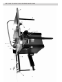
1
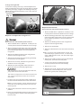
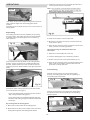
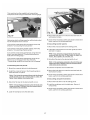
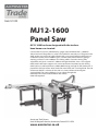
Code: 501198
MJ12-1600
Panel Saw
MJ12-1600 has been designed with the trade or
keen home user in mind.
Constructed in cast iron, welded heavy gauge steel and fitted with a 1,600mm
alloy extrusion sliding table, it is robust and stable for everyday use. The good sized,
deep section cast iron main table is fitted with a cast iron extension table giving a
combined surface of 825 x 800mm, plus a further steel plate extension giving a
working surface of 1,265 x 800mm. The sliding table is smooth running, fully
adjustable, and gives a travel of 1,300mm through the blade. A cross-cut support
table, with a telescopic support arm, can be positioned anywhere on the sliding
table and has a telescopic fence 1,200-2,200mm long, enough for full size boards. A
powerful 2.2kW 1ph motor drives both the main blade and a scoring blade. The size
of the main blade is a choice of 254, 305 or 315mm, without removing the
scoring blade. The scoring blade is easy to adjust through the
table top and can be retracted below the surface.
when not required.
Axminster Tool Centre,
Unit 10 Weycroft Avenue, Axminster, Devon EX13 5PH
www.axminster.co.uk
CONTENT
SPECIFICATIONS
SAFETY
Safety Instructions for Power Tools
Additional Safety Instructions for Panel Saws
Protecting Kickback
SITE CONSIDERATIONS
GETTING TO KNOW YOUR PANEL SAW
UNPACKING
Piece Inventory
Clean Up
ASSEMBLY
Moving & Placing Saw Base Unit
Install the extension table
Install the support leg
Install the rip fence rail
Install the rear support rail
Install the rear extension table
Install the main blade elevation
& angle handwheel
Fitting the rip fence and align the rail
Install the swing arm assembly
Install the Sliding panel assembly
Adjust the sliding panel level
Install the cross cut table
Install the cross cut fence
1
2
2
3
3
4
5
7
7
7
8
8
8
9
9
9
9
9
10
10
10
11
11
11
Install the hold down
Install the dust port
Install the blade guard
Install the dust hose support
Install dust hoses
REPLACEMENT & ADJUSTMENT
Replace the main blade
Replace and adjusting the scoring blade
Replace and adjust the riving knives
Replace the main belt
Replace the scoring belt
Sliding Table Parallel Adjustment
OPERATIONS
Rip Cutting
Crosscutting
Miter Cutting
MAINTENANCE
ELECTRICAL
Main switch
Limit switch
Thermo cut-out
Wiring Diagram
TROUBLESHOOTING
PARTS LIST & DIAGRAMS
11
12
12
12
12
13
13
14
14
14
15
15
16
16
16
18
19
19
19
19
19
20
21
22
SPECIFICATIONS
Model
Motor power
Major table size
Extension table (Cast iron)
Extension table (Steel plate)
Rear extension table
Sliding panel size
Cross cut table size
Cross cut fence
Main blade size
Main blade speed
Scoring blade size
Scoring blade speed
Max cut depth
MJ12-1600
230V/400V ~, 50Hz, 3000 W
385x800 mm
MJ12-1800
MJ12-2000
230V/400V ~, 50Hz, 3000 W
385x800 mm
230V/400V ~, 50Hz, 3000 W
385x800 mm
440x800 mm
440x800 mm
440x800 mm
440x800 mm
440x800 mm
440x800 mm
310x500 mm
310x500 mm
310x500 mm
1600 x 270 mm
1800 x 270 mm
2000 x 270 mm
680x580 mm
680x580 mm
680x580 mm
1200-2200 mm
1200-2200 mm
1200-2200 mm
315x30x3 mm
315x30x3 mm
315x30x3 mm
4000 rpm
4000 rpm
4000 rpm
90x20x3 mm
90x20x3 mm
90x20x3 mm
5800 rpm
5800 rpm
5800 rpm
100 mm @ 90 O(315)
100 mm @ 90 O(315)
100 mm @ 90 O(315)
80 mm @ 45 O(315)
80 mm @ 45 O(315)
80 mm @ 45 O(315)
Max distance-blade to rip fence
1220 mm
1220 mm
1220 mm
Max cross cut width
Sliding panel stroke
Packing size
1350 mm
1350 mm
1350 mm
1600 mm
1800 mm
2000 mm
940x765x1010 mm
940x765x1010 mm
940×765×1010 mm
1660x250x320 mm
Weight(N.W/G.W)
Noise level (Unload)
1860x250x320 mm
250/290 kg
255/295 kg
85 dB( A)
85 dB( A)
2060×250×320 mm
260/300 kg
85dB(A)
NOTE: The above specifications and the constructions were current at the time this manual was published, but
because of our policy of continuous improvement, we reserve the right to change specifications and the
constructions without notice and without incurring obligations.
1
)
)
should be in accordance with amperage rating. An
undersized cord will cause a drop in line voltage
resulting in loss of power and overheating. Your
extension cord must also contain a ground wire.
Always repair or replace extension cords if they
become damaged.
SAFETY
For Your Own Safety, Read Instruction Manual
Before Operating this Equipment
10. WEAR PROPER APPAREL. DO NOT wear loose
clothing, gloves, neckties, rings, bracelets, or other
jewelry which may get caught in moving parts. Nonslip footwear is recommended. Wear protective hair
covering to contain long hair.
The purpose of safety symbols is to attract your
attention to possible hazardous conditions. This
manual uses a series of symbols and signal words
which are intended to convey the level of
importance of the safety messages. The
progression of symbols is described below.
Remember that safety messages by themselves do
not eliminate danger and are not a substitute for
proper accident prevention measures.
11. ALWAYS USE SAFETY GLASSES. Also use face or
dust mask if cutting operation is dusty. Everyday
eyeglasses only have impact resistant lenses, they
are NOT safety glasses.
12. SECURE WORK. Use clamps or a vise to hold work
when practical. It is safer than using your hand and
frees both hands to operate tool.
Indicates an imminently hazardous situation which,
if not avoided, WILL result in death or serious injury.
13. DO NOT OVERREACH. Keep proper footing and
balance at all times.
Indicates a potentially hazardous situation which, if
not avoided, COULD result in death or serious
injury.
14. MAINTAIN TOOLS WITH CARE. Keep tools sharp
and clean for best and safest performance. Follow
instructions for lubricating and changing
accessories.
Indicates a potentially hazardous situation which, if
not avoided, MAY result in minor or moderate injury.
It may also be used to alert against unsafe
practices.
15. USE RECOMMENDED ACCESSORIES. Consult
the instruction manual for recommended
accessories. The use of improper accessories may
cause risk of injury.
16. REDUCE THE RISK OF UNINTENTIONAL
STARTING. On machines with magnetic contact
starting switches there is a risk of starting if the
machine is bumped or jarred. Always disconnect
from power source before adjusting or servicing.
Make sure switch is in OFF position before
reconnecting.
This symbol is used to alert the user to useful
information about proper operation of the
equipment.
Safety Instructions for Power Tools
17. MANY WOODWORKING TOOLS CAN
“KICKBACK” THE WORKPIECE toward the
operator if not handled properly. Know what
conditions can create “kickback” and know how to
avoid them. Read the manual accompanying the
machine thoroughly.
1. KEEP GUARDS IN PLACE and in working order.
2. REMOVE ADJUSTING KEYS AND WRENCHES.
Form a habit of checking to see that keys and
adjusting wrenches are removed from tool before
turning on.
4. DO NOT USE IN DANGEROUS ENVIRONMENT. DO
NOT use power tools in damp or wet locations, or
where any flammable or noxious fumes may exist.
Keep work area well lighted.
18. CHECK DAMAGED PARTS. Before further use of
the tool, a guard or other part that is damaged
should be carefully checked to determine that it will
operate properly and perform its intended function.
Check for alignment of moving parts, binding of
moving parts, breakage of parts, mounting, and any
other conditions that may affect its operation. A
guard or other part that is damaged should be
properly repaired or replaced.
5. KEEP CHILDREN AND VISITORS AWAY. All children
and visitors should be kept at a safe distance from
work area.
19. NEVER LEAVE TOOL RUNNING UNATTENDED.
TURN POWER OFF. DO NOT leave tool until it
comes to a complete stop.
6. MAKE WORKSHOP CHILD PROOF with padlocks,
master switches, or by removing starter keys.
20. NEVER OPERATE A MACHINE WHEN TIRED, OR
UNDER THE INFLUENCE OF DRUGS OR
ALCOHOL. Full mental alertness is required at all
times when running a machine.
3. KEEP WORK AREA CLEAN. Cluttered areas and
benches invite accidents.
7. DO NOT FORCE TOOL. It will do the job better and
safer at the rate for which it was designed.
21. NEVER ALLOW UNSUPERVISED OR UNTRAINED
PERSONNEL TO OPERATE THE MACHINE. Make
sure any instructions you give in regards to the
operation of the machine are approved, correct,
safe, and clearly understood.
8. USE RIGHT TOOL. DO NOT force tool or attachment
to do a job for which it was not designed.
9. USE PROPER EXTENSION CORD. Make sure your
extension cord is in good condition. Conductor size
2
Additional Safety Instructions for Panel
Saws
No list of safety guidelines can be complete.
Every shop environment is different. Always
consider safety first, as it applies to your
individual working conditions. Use this and
other machinery with caution and respect.
Failure to do so could result in serious
personal injury, damage to equipment, or poor
work results.
1. SAFETY ACCESSORIES. Always use the blade
guard and riving knife on all ''through-sawing''
operations. Through-sawing operations are those
when the blade cuts completely through the workpiece.
2. KICKBACK. Be familiar with kickback. Kickback
happens when the work-piece is thrown towards the
operator at a high rate of speed. Until you have a
clear understanding of kickback and how it occurs,
DO NOT operate this table saw!
Statistics prove that most common accidents
among table saw users can be linked to
kickback. Kickback is typically defined as the
high-speed expulsion of stock from the table
saw toward its operator. In addition to the
danger of the operator or others in the area
being struck by the flying stock, it is often the
case that the operator's hands are pulled into
the blade during the kickback.
3. WORKPIECE CONTROL. Make sure the work-piece
is placed in a stable position on the table and is
either supported by the rip fence or the crosscut
table during cutting operations.
4. PUSH STICK. Always use a push stick when ripping
narrow stock.
5. OPERATOR POSITION. Never stand or have any
part of your body directly in-line with the cutting path
of the saw blade.
Preventing Kickback
Never attempt freehand cuts. If the work-piece is not
fed perfectly parallel with the blade, a kickback will
likely occur. Always use the rip fence or crosscut
fence to support the work-piece.
6. REACHING OVER SAW BLADE. Never reach behind
or over the blade with either hand while the saw is
running. If kickback occurs while reaching over the
blade, hands or arms could be pulled into the
spinning saw blade.
Make sure the riving knife is always aligned with the
blade. A misaligned riving knife can cause the workpiece to bind or stop the flow of the cut, resulting in
an increased chance of kickback. If you think that
your riving knife is not aligned with the blade, check
it immediately!
7. USING THE RIP FENCE AND THE CROSSCUT
FENCE TOGETHER DURING A CUTTING
OPERATION. When using the crosscut fence, the
work-piece should never be contacting the rip fence
while the saw blade is cutting.
8. STALLED BLADE. Turn the saw off before
attempting to "free" a stalled saw blade.
Ensure that your table slides parallel with the blade;
otherwise, the chances of kickback are extreme.
Take the time to check and adjust the sliding table.
9. COMFORTABLE CUTTING OPERATIONS. Avoid
awkward operations and hand positions where a
sudden slip could cause your hand to move into the
spinning saw blade.
Use the riving knife during every cut. The riving
knife helps maintain the kerf in the work-piece after
it is cut, therefore, reducing the chance of kickback.
Feed cuts through to completion. Anytime you stop
feeding a work-piece that is in the middle of a cut,
the chance of binding, resulting in kickback, is
greatly increased.
10. EXPERIENCING DIFFICULTIES. If at any time you
are experiencing difficulties performing the intended
operation, stop using the machine! Contact your
agent.
11. BLADE HEIGHT. Always adjust the blade to the
proper height above the work-piece.
Protecting Yourself from Kickback
12. DAMAGED SAW BLADES. Never use blades that
have been dropped or otherwise damaged.
Even if you know how to prevent kickback, it may
still happen. Here are some tips to reduce the
likelihood of injury if kickback DOES occur:
13. RIVING KNIFE ALIGNMENT. Only operate the saw
if the riving knife is aligned with the main blade.
Stand to the side of the blade during every cut. If a
kickback does occur, the thrown
Work-piece usually travels directly in front of the
blade.
Always wear safety glasses or a face shield. In the
event of a kickback, your eyes and face are the most
vulnerable part of your body.
Like all machines there is danger associated
with this Sliding Panel Saw. Accidents are
frequently caused by lack of familiarity or
failure to pay attention. Use this machine with
respect and caution to lessen the possibility of
operator injury. If normal safety precautions
are overlooked or ignored, serious personal
injury may occur.
Never, for any reason, place your hand behind the
blade. Should kickback occur, your hand will be
pulled into the blade.
Use a push stick to keep your hands farther away
from the moving blade. If a kickback occurs, the
push stick will most likely take the damage that your
hand would have received.
3
SITE CONSIDERATIONS
General Condition:
1.Electrical connection: Steady state voltage: 0.9-1.1
of nominal voltage.
Frequency: 0.99-1.01 of nominal frequency
continuously; 0.98-1.02 short time
The mains connection must have maximum16A fuse.
Electrical supply which has protection devices of
under-voltage, over-voltage, over-current as well as
a residual current device (RCD) which maximum
residual current rated at 0.03A.
2. Altitude are not exceeding 1000m,
Maximum ambient air temperature is +40 OC,
minimum ambient air temperature is not less than
+5 OC,
Storage and transportion temperature range is
-25 OC~+55 OC.
The relative humidity does not exceed 50% at a
maximum temperature of +40 OC, higher relative
humidity may be permitted at lower temperature
(e.g. 90%@ 20 OC).
3600mm
Lighting and Outlets
Lighting should be bright enough to eliminate shadow
and prevent eye strain. Electrical circuits should be
dedicated or large enough to handle combined motor
amp loads. Outlets should be located near each
machine so power or extension cords are not
obstructing high-traffic areas. Be sure to observe local
electrical codes for proper installation of new lighting,
outlets, or circuits.
Floor Load
This machine represents a moderately large weight
load in a small footprint. Most commercial shop floors
will be adequate for the weight of the machine. Some
floors may require additional support. Contact an
architect or structural engineer if you have any question
about the ability of your floor to handle the weight.
Dust Collector
As a rule, this machine must be vacuumed during use. A
time relayed socket is available as an accessory. In
addition, the vacuum performance must be sufficient to
achieve the required negative pressures and a
maximum air speed of 20m/sec at the connector.
To ensure sufficient upright stability of the machine
it should be bolted to floor. For this purpose 4 holes
are provided in the machine' s bracket of workstand.
Read the manual before assembly and operation.
Become familiar with the machine and it's
operation before beginning any work. Serious
personal injury may result if safety or operational
information is not understood or followed.
Working Clearances
Working clearances can be thought of as the distances
between machines and obstacles that allow safe
operation of every machine without limitation. Consider
existing and anticipated machine needs, size of
material to be processed through each machine, and
space for auxiliary stands and/or work tables. Also
consider the relative position of each machine to one
another for efficient material handling. Be sure to allow
yourself sufficient room to safely run your machines in
any foreseeable operation.
Consider existing and anticipated needs, size of
material to be processed through each machine, and
space for auxiliary stands, work tables or other
machinery when establishing a location for your saw.
See above figure for the maximum working clearances
of the Sliding Panel Saw.
4
GETTING TO KNOW YOUR SLIDING PANEL SAW
5
A. Crosscut Table–Provides a wide, stable platform for
supporting full-size panels during crosscutting
operations.
K. Blade Angle Hand-wheel–Adjust the angle of the
saw blades.
L. Mitre Gauge–This gauge aligns the wood for a
cross-cut.
B. Flip Stops–Used for quick measurements for
crosscutting.
M. Rip Fence–Fully adjustable with fine adjustments.
Fence face can be positioned for standard cutting
operations, or in the lower position for blade guard
clearance during narrow ripping operations.
C. Crosscut Fence–Used during crosscutting
operations. Features a scale and multiple flip-style
stopblocks for precise, repeatable crosscutting
operations.
N. Fence Assembly Lock Down lever–Secures the
fence assembly into position along the fence rail.
D. Roller–Used for supporting full-size panels during
crosscutting operations.
P. Fine-Adjust Knob–Precisely adjusts the fence.
E. Sliding Panel–Conveniently glides the work-piece
through the blade with effortless precision and ease.
Q. Rip Fence Rail–Provides the support for rip fence.
F. Blade Guard–Fully-adjustable blade guard allows
high visibility of the cutting operation while
maintaining maximum protection around the saw
blade.
R. Support Leg–Provides the support for the extension
table.
S. Main Blade Angle Lock Knob–Secures the angle of
main blade.
G. Rear extension table
T. Hold Down w/Mitre Gauge – Holds the work-piece for
sliding or mitre cutting .
H. Power Switch–Start/stops the machine and has
emergency stop function.
J. Blade Elevation Hand-wheel–Adjust the height of
the main saw blade.
U
V
1 2
3
W
U. Riving Knife–Maintains kerf during cutting
operations. This function is crucial to preventing
kickback caused by the kerf closing behind the
blade.
1. Scoring Blade Alignment Screw–Adjusts the
lateral movement of the scoring blade.
2. Scoring Blade Lock Screw–Locks the scoring blade
after adjusted.
V. Main Blade–Performs the cutting operations.
3. Scoring Blade Elevation Screw–Adjusts the height
of the scoring blade.
W. Scoring Blade–Small cutting blade that rotates
opposite the main saw blade. The blade scores the
workpiece before the actual cutting operation is
performed; thus, preventing tear-out in laminate
materials. The scoring blade is adjustable forward
and backward, up and down, and in thickness of kerf.
6
UNPACKING
The Sliding Panel Saw is shipped from the
manufacturer in a carefully packed crate. If you
discover the machine is damaged after you have
signed for delivery, please call Customer Service
immediately for advice. When you are completely
satisfied with the condition of your shipment, you
should inventory its parts.
The Sliding Panel Saw is a heavy
machine. DO NOT over-exert yourself
while unpacking or moving your
machine you will need assistance and
power equipment. Serious personal
injury may occur if safe moving
methods are not followed.
Clean Up
The unpainted surfaces are coated with a light oil to
protect them from corrosion during shipment. Remove
this protective coating with a solvent cleaner or citrusbased degreaser. To clean thoroughly, some parts may
need to be removed. For optimum performance from
your machine, make sure you clean all moving parts or
sliding contact surfaces that are coated. Avoid chlorinebased solvents as they may damage painted surfaces
should they come in contact.
Do not use gasoline or other petroleum-based
solvents to clean with. They have low flash
points which make them extremely flammable. A
risk of explosion and burning exists if these
products are used.
Some metal parts may have sharp edges on
them after they are formed. Please examine
the edges of all metal parts before handling
them. Failure to do so could result in injury.
Many of the solvents commonly used to clean
machinery can be toxic when inhaled or
ingested. Always work in well ventilated areas
far from potential ignition sources when dealing
with solvents. Use care when disposing of waste
rags and towels to be sure they do not create fire
or environmental hazards.
Piece Inventory
After all the parts have been removed from the carton,
you should have:
Main crate
Main saw unit
Cast iron extension table
Steel plate extension table w/support leg
Rear extension table w/support
Swing arm assembly (inside main saw unit)
Cross cut table
Roller, cross cut
Blade guard
2-1/2" dust hose
Dust port
Mitre gauge
Hand wheels (2)
Hardwares
Tools
13-15 mm open head wrench
Arbor wrench
Arbor pin
3, 4, 5, 6 mm "L" wrench
Push stick
(Some parts are inside the main saw unit)
Edge shoe
Rail crate
Rip fence
Rip fence rail
Rear support rail
Sliding table
Sliding table carrier
Support leg, sliding carrier
Cross cut fence
Hold down w/fence
Flip stop
7
ASSEMBLY
1 . Attach the Cast iron extension table to major table
with 4-M8x20 hex head screws / washers .
Moving & Placing Saw Base Unit
The Sliding Panel Saw is a heavy machine. Serious
personal injury may occur if safe moving methods
are not followed. To be safe, you will need
assistance and power equipment when moving the
shipping crate and removing the machine from the
crate.
Use lifting straps with a minimum of 500 kgs lifting
capacity. If the lifting strap breaks, serious personal
injury may occur.
Fig 2
1. Remove the top of crate and position the forklift forks
together and directly above the saw.
2 . Center the extension table over the edges and tap it.
Check the surface alignment.
2. Place four lift rings onto Saw Base Unit and place two
lifting straps over the forks and attach the lifting rings
.
3. Insert a wood block for protecting the main switch.
Major Table
Fig 3
Wood Block
Extension Table
4. Lift the saw base unit and move it to your
predetermined location.
5. Before lowering the saw into position, place four
rubber blocks under the frame.
View From Front
6. Lower the saw on the floor.
Extension Table
Major Table
Tap Here
View From Top
Major Table
Tap Here
Extension Table
3 . Tighten 4-screws with 13 mm open head wrench.
Attach the steel plate extension table to cast iron
extension table , Aligned and tighten them as “install the
cast iron extension table”.
Fig 1
Install the extension table
Fig 4
Take out the cast iron extension table, steel plate
extension table and rear extension table from the Saw
Base Unite crate.
The cast iron extension table is heavy part that
weighs over 35 kgs. To be safer, you will need
assistance.
8
Install the support leg
Fig 7
1. Attach the support leg to steel plate extension table
with 2-M8x20 Hex head screws, washers and nuts.
And tighten them.
2 . Adjust the support leg ensure the steel plate
extension table at the same lever with the cast iron
extension table.
Install the rip fence rail
1. Place 5-M8x25 square head screws, washers and
hex nuts onto major table and extension tables
(washers and nuts inside table). The nuts only need
to be turn a few turn so there is an adequate gap to fit
the rip fence rail.
Install the rear extension table
1. Attach the rear extension table to the rear portion of
major table with 2-M8x16 hex head screws washers,
hex nuts.
2. Remove the left end cap of rip fence rail. Slide the
slot on the rip fence rail over 5-bolts. Adjust each bolt
to fit the rail closely to table.
3. Push the rail against the tables and hand tight each
hex nut. The rail needs further adjustment.
2. Place the bracket onto rear panel of saw base unit
with a M8x16 hex head screw, another end of bracket
mounted to rear extension table with a M8x16 hex
head screw.
4. Put the left end cap onto rail, and tighten it with taping
screws.
3. Align the rear extension 0.5mm lower than the major
table.
Rip Fence Rail
Fig 5
Fig 8
Support Leg
Install the main blade elevation & angle
handwheel
1. Fitting the elevation handwheel(1) and angle
handwheel (2) onto the elevation and angle shaft.
Rip Fence
Rail
Square Head
Screw
2. Tighten the set screws with 3mm 'L' wrench.
Fig 9
Fig 6
1
Install the rear support rail
Attach the rear support rail onto the cast iron and
steel plate extension tables, with 4-M8x25 square
head screws, washers and nuts, tighten them.
9
2
Fitting the rip fence and align the rail
1.Move the blade tilt to 0˚ (blade 90˚ to table), and raise
the main blade as the way up.
2 . Place the cross-cut table support (A) onto the swing
arm assembly, and hand tighten the lock nuts. The
support needs further adjustment.
2.Fit the profile of the rip fence carrier into the opposite
profile on the rip fence rail.
Install the Sliding panel assembly
3.Slide the rip fence touch the main blade.
1 . Place 2 sets of star-type screws (include 8mm
washer, insert, screw guide) into the lower slot of
sliding panel carrier ( see above 14).
4. Tap the right end of rip fence rail to ensure the '0'
scale on rail aligned with the red line on lens of rip
fence carrier.
Fig 12
Fig 10
2. Put the sliding panel assembly onto the sliding panel
supports, and lay two star-type screws as fig 15 show.
Fig 13
C
A
Install the swing arm assembly
1 . Place 4 M8x30 hex head screws to mount the swing
arm assembly to the saw base unit, and keep the arm
on horizontal level.
B
3. Tighten two star-type screws.
Fig 11
A
Fig 14
4. Install the support leg to the sliding carrier.
10
Adjust the sliding panel level:
Install the cross cut fence
1 . Place a level rule (cross cut fence) on to major table
and sliding panel .
1. Drop the cross cut fence into the forward or rear guide
pin hole.
2. Loosen 4-M8x25 hex screws(A) , adjust the M8x40
hex screw(B) to adjust the sliding panel level(fig 13).
2. Tighten the knurled nut.
3. Then re-tighten 4-M8x25 hex screws (A).
3. Turn the “Z” lock plate to quick aligning the fence to
table.
4. To fine adjust, using 3 mm “L” wrench to adjust 4M8x12 set screws(C).
4 .Turn the star type screw and clamped the fence in
position.
Install the push handle and lock pin
5. Slide the flip stop(D) into the fence.
1 . Sliding the M12x1.75 T-nut into the sliding panel and
thread in push handle(D) with a 17 mm open end
wrench.
6.Place a T-nut into the top slot of fence, thread the
stud of hold-down on fence.
7.If need, put the hold down arm onto the stud (E).
2. Insert the star-type lock pin (E) into sliding panel, and
lock the M10 hex nut on the opposite side.
E
D
Fig 1
D
D
Fig 15
E
Install the cross cut table
1. Slide two M8x70 carriage bolts with T- l blocks into the
side slot of sliding panel . Attached the crosscut table
to sliding panel .
2. Use 2 wing nuts mounted the cross cut table to sliding
panel.
3 . Use 2 M6x30 Hex head scews mounted the cross cut
table to support(B).
Install the hold down /Mitre Gauge
4 . Adjust 4-M12 thin hex nut (C) to adjust the cross cut
table on the line with sliding panel.
1. Slide the hold down/Mitre Gauge onto the sliding
table and push it as far as possible. And lock the hold
down/mitre gauge on table with the star-type lock
handle (A) locked.
5. Then tighten 4-M12 thin nut (C).
2. A ligned the Mitre Gauge fence on it.
Fig 16
Fig 18
B
C
11
Install the dust port
Install dust hoses
Place the dust port onto the bottom of rear panel,
tighten it with 4 M6x12 pan head screws washers and
nuts (nuts inside stand).
Fig 19
1. Install the 2” dust hose onto the blade guard with 2”
hose clamp.
2. Put the 2” dust hose onto dust hose support, keep
free with the working table.
3. Another end of 2” dust hose clamps to the main dust
port on the bottom of rear panel.
4. Install 4” dust hose to main dust port with 4” hose
clamp
Fig 22
Install the blade guard
The riving knife cuts 3 slot for different blade size.
For PS10 the blade guard mounts to the 254 slot.
For PS12, if using the 254 mm blade place the blade
guard onto 254 slot; if using the 305 or 315 mm place
the blade onto 315 slot.
Fig 23
Fig 20
Install the dust hose support
Fig 24
To install the dust hose support onto the rear portion of
steel plate extension table with 2 M6x20 hex head
screws washers and nuts( nuts under the table).
Fig 21
12
REPLACEMENT & ADJUSTMENT
Fig 25
Replace the main blade
Disconnect the saw from the power source!
The main blade dimension suitable for MJ12 machine is
254x30x3( outer diameter, core diameter, thickness),
305x30x3, 315x30x3mm.
Replace and adjusting the scoring blade
But any time you change blade thickness, the
appropriate sized riving knife and scoring blade
must also be changed to match the size of main
blade you install.
To change main blade:
1. Move the blade tilt to 0˚ (Blade 90˚ to table) on the
control panel and raise the blade as far as it will go.
Disconnect the saw from the power source!
Suitable for machine is 90x20x3( outer diameter, core
diameter, thickness) mm Tapered Scoring Blade.
To replace scoring blade:
1. Move the blade tilt to 0˚ (Blade 90˚ to table) on the
control panel and raise the blade as far as it will go.
2. Move the sliding panel all the way to the right and
remove two M6x12 pan head screws to expose the
internal blade guard that covers the blades and
riving knife.
2. Move the sliding panel all the way to the left and
remove two M6x12 pan head screws to expose the
internal blade guard that covers the blades and
riving knife.
3. Remove the blade guard from the riving knife to
expose the mounting assembly.
4. Remove the table insert.
3. Remove the blade guard from the riving knife to
expose the mounting assembly.
5. Insert the arbor pin into the hole on blade inner
flange and locks the blade.
4. Remove the table insert.
5. Insert the arbor pin into the hole on blade inner
flange and locks the blade.
6. Using the arbor wrench, remove the arbor nut that
secures the main blade (turn clockwise to loosen).
6. Using the arbor wrench, remove the arbor nut that
secures the main blade (turn anti-clockwise to
loosen).
7. Remove the arbor flange and the old main blade.
8. Install the new main blade, replace the arbor flange
and nut, and tighten the arbor nut to secure the
main blade.
If you changed blade diameter sizes during this
procedure, now is the time to adjust the riving knife.
(Just for MJ12 )
7. Remove the arbor flange and the old scoring blade.
8. Install the new scoring blade, replace the arbor
flange and nut, and tighten the arbor nut to secure
the scoring blade.
Fig 26
If the kerf thickness is different from your old blade,
the scoring blade kerf and riving knife thickness
must match the new main blade kerf.
9. Make sure the correct size riving knife is installed
and aligned with the blade.
10. Move the internal blade guard back into its original
position, next to the blades, and center the sliding
panel.
11. Align the scoring blade to the main blade .
13
To align s coring blade:
Fig 28
Loosen the cl a mpi n g screw (A). Late ra l adjustment i s
made vi a adjusting scr e w (B). the h eight setting is m a de
via setti n g s c rew (C ) . r e tighten the cla m pin g screw (A ) .
A d just the s co r i n g blade l aterally so it i s i n line with the
main sa w -bla d e.
3- 8mm
Fig 27
B
C
A
R epl a ce th e ma i n belt
D is c onnect the saw fr om the pow er source!
1. Move t he bl a de t i lt to 0˚ (Blad e 90˚ t o table) on the
control p anel and raise the blad e as far a s i t w i ll go.
R e place and adjust t he riving knives
2 . Move t he slidin g pan e l a l l th e way t o the left and
remove two M6 x 12 pan head scr e ws to expo s e t h e
i n ternal blade guard that covers th e bl a des and
riving k nife .
Disconnect the saw from the power s our c e !
3 . Remove the blade guard fro m the rivi n g k n ife t o
expos e the mo u nting assembly.
1 . Mo v e t h e blade t ilt to 0˚ (Blade 90˚ t o tab l e) on the
control panel and rais e the blade as far as it will g o .
4 . Remove the main b l ade.
2. Mo v e t h e s l iding panel all the way t o the right and
remove tw o M6x12 pan head scre w s to expose th e
internal blade gua r d that cov e rs the blades and
riving knife.
5 . Remove 3 M8x18 A l len screw and remove the chip
house.
Note To r emov e lower 2 -M8x 1 8 A l len s crews, the
main blade angle s y stem tilt to 30˚, to remove the
upper 1-M8x18 Al le n screw , t h e main blade angle
s y stem tilt to 0˚ .
3. Remove th e bl a de g u ard from the riving knife t o
e x pose the mounting assemb l y.
4. Remove th e center bolt in the moun t ing assembly
to remo v e the mounting pla t e.
6 . Remove the 4 Allen scre w s on t h e to p and bo t t o m
of left p anel, and remo v e the lef t panel.
5. Remove th e cu rr ently installed riving knife and
install the correc t rivin g knife.
7 . Loo s en motor a mount 4-M8x40 hex hea d
s c rews(A) and loosen t h e te n sion bol t (B).
6. Replace th e m o unting plat e and threa d in the
center b o lt with o ut completely tighte n ing it.
8 . R e move the V-be l t.
9 . R e place n e w V- b elt, t ighten mot o r bolt s an d the
te n sion bol t , close t he le f t panel, a n d re-m o unt
blade i nner guard, b lade, blade gu a rd.
Th e riving knife i s c arved with d i fferent b lade size,
just p u t the carv e d l i ne u nder table.
Th e ce n ter car r i a ge bolt i s mounted in a h o rizon t al
slot, so the rivi n g knife can mov e far o r nea r the
m a in b lade.
7. Posi t ion t h e riv i ng k nife abou t 3mm to 8mm away
from the nearest c a rbide tooth on the main b l ade.
N ote Fo r a quick ga u ge, u se t he 3 m m h ex wren c h
to find the c orrect spacing between the blade and
the rivi n g knife.
8. Tig h ten t he center b o lt to secure the riv i ng knife in
p o sitio n .
9. Mo v e the int e rnal blade guard (fr o m step 4) bac k to
its orig i nal posit i on, and m ove the slid i ng p anel
back to center.
Fig 29
14
2. Raise the main blade up as far as it will go.
Fig 30
3. Mark the center of the blade with a felt tip pen. This
will allow you to take your measurements from the
exact same place on the blade.
4. Move the sliding panel all the way to one end, and
using a precision ruler, measure the gap between
the edge of the panel and your mark on the blade as
shown in Fig 32.
A
Fig 32
B
Blade
Sliding
Table
Mitre
Slot
Replace the scoring belt
B
A
Disconnect the saw from the power source!
1. Move the blade tilt to 0˚ (Blade 90˚ to table) on the
control panel and lower the blade as far as it will go.
2. Remove the 4 Allen screws on the top and bottom
of right panel, and remove the left panel.
5. Move the other end of the sliding panel in front of
the blade and measure the gap.
3. Push the tension pulley as far as it will go as arrow
show.
If the gap is the same on both sides, then the sliding
panel is already parallel with the main blade.
4. Remove the old belt and replace new belt.
If the gap on one side is different than the other, then
continue with step6.
5. Re-mount the right panel.
Fig 31
6. Move the end of the sliding panel that needs to be
adjusted in front of the blade.
7. Loosen the two hex head screws (C) and light tap
the sliding carrier support to adjust the gap.
C
Sliding Panel Parallel Adjustment
Disconnect the saw from the power source!
Now is the point in the assembly process to make the
sliding panel parallel with the main saw blade and
secure the sliding panel to the saw base.
Besides the tools included with the saw, this procedure
requires you to have a precision ruler, a felt tip pen, and
the assistance of another person.
To adjust the sliding panel parallel with the main
blade:
1. Set the blade to 0˚ on the control panel (90˚ with the
cast iron table).
Fig 33
8. Repeat steps 7 until the gap between your mark on
the blade and the edge of the sliding panel is even at
both ends.
9. Tighten the four hex head screws (C) and secure
supports in place
10. Now tighten the two star-type screws that secure
the sliding panel to the base.
15
3. Install the crosscut fence in the guide pin holes and
lock it in place with the knurled nut.
OPERATIONS
Note First, drop the crosscut fence into the forward
guide pin hole, turn the "Z"lock plate to align the
fence, then tighten the knurled nut.
Fig 34
Your safety is important. To preventing work-piece kickback, slide the edge shoe into sliding panel when
needed.
The edge shoe can slide into the front or rear portion of
sliding panel.
Rip Cutting
Fig 37
The sliding panel saw has the capability of rip cutting
full size panels. The sliding panel removes the burden
of sliding a large and heavy panel over a stationary
table surface.
4. Set either flip stop to the desired width-of-cut.
5. Load the workpiece onto the table saw.
6. Mount the hold down arm onto the stud and lock the
work-piece in place.
Fig 35
7. Once all the necessary safety precautions have been
taken, perform the cutting operation.
Rip cutting using the traditional table saw
technique:
1. Slide the crosscut table out of the way.
2. Lock the sliding panel into a stationary position.
3. Position the rip fence to the desired width-of-cut.
This saw also has the capability of rip cutting smaller
boards, using the machine as a traditional table saw.
Smaller, lighter boards are easier to slide across the
stationary cast iron table surface to the right of the saw
blade.
4. Once all the necessary safety precautions have been
taken, load the workpiece onto the table saw and
perform the cutting operation.
Crosscutting
With the crosscut fence mounted in the forward
position, the sliding panel saw has the capability of
crosscutting full size panels.
Fig 38
Fig
Fig 36
36
Determine which cutting operation will be best suited
for the workpiece to be ripped.
To use the sliding table, read the instructions titled
“Rip cutting with the sliding panel.”
With the crosscut fence mounted in the rear position,
this machine also has the capability of crosscutting
smaller panels.
Fig 39
To use the machine as a traditional table saw, skip
ahead to “Rip cutting using the traditional table saw
technique.”
Rip cutting with the sliding panel:
1. Mount the crosscut table to the sliding panel.
2. Slide and secure the crosscut table to the end of the
sliding table opposite the sliding table handle.
16
Miter Cutting
Note If the workpiece extends to the left of the saw
blade more than 1200mm, then the crosscut fence
slide needs to be extended.
The cross cut table built two scales for forward and rear
mount fence to perform mitre cut.
4. Load the workpiece onto the table saw.
5. Mount the hold down arm onto the stud and lock the
work-piece in place.
6. Once all the necessary safety precautions have
been taken, perform the cutting operation.
To perform a miter cut using the hold down w/mitre
gauge:
Fig 41
Also the sliding panel built a scale for hold down to
perform mitre cut.
Fig 44
1. Mount the hold down onto sliding panel and fit a cut
fence.
2. Position the hold down w/mitre gauge at the
desired angle and use the ratchet lever to lock the
mitre gauge in position.
3. Load the workpiece onto the sliding panel. Secure
the workpiece with clamp.
4. Once all the necessary safety precautions have
been taken, perform the cutting operation.
Fig 46
Lastly, this machine has the capacity of mitre cutting
work-piece using the mitre gauge.
To perform a miter cut using the cross cut fence:
1. Mount the cross cut fence onto the cross cut table.
2. Position the cross cut fence at the desired angle
and use the ratchet lever to lock the cross cut fence
in position.
Fig 45
3.Position the flip stop according to the length of the
workpiece you want to cut off to the left of the blade.
18
MAINTENANCE
ELECTRICAL
Main switch
Always disconnect power to the machine before
performing maintenance. Failure to do this may
result in serious personal injury.
This machine is equipped with a knee touch no-volt
release main switch and a limit switch.
Cleaning
The main switch is equipped a large size touch panel,
during performance cutting work, any part of man body
touched the switch panel, it can bring the saw stop.
Cleaning the sliding panel saw is relatively easy.
Vacuum excess wood chips and sawdust, and wipe off
the remaining dust with a dry cloth. If any resin has built
up, use a resin dissolving cleaner to remove it. Treat all
cast iron and unpainted steel with a non-staining
lubricant after cleaning.
Once a week:
Clean sliding panel surface and grooves.
Clean the cast iron or steel plate saw table.
Clean the roller guide ways for the sliding table.
Clean the aluminum rip fence and sliding grooves.
Clean the rip fence bracket.
Once a month:
Vacuum inside the motor cabinet.
Miscellaneous
Always be aware of the condition of your machine.
Routinely check the condition of the following items and
repair or replace as necessary:
Loose mounting bolts.
Worn switch.
Worn or damaged blade.
Worn or damaged blade guard.
Fig 47
Limit switch
The limit switch is mounted under the inner guard, if
your make scoring blade or main blade replacement,
remove the inner guards, the limit switch keep “off”
position. Reduce the risk of unintentional starting.
V-Belts
To ensure optimum power transmission from the motor
to the blade and to the hydraulic pump, the V-belts must
be in good condition (free from cracks, fraying and
wear) and operate under proper tension. Check the Vbelts at least every 3 months; more often if the saw is
used daily.
Fig 48
Replace the belts, if needed.
Thermo cut-out
Bearings
The bearings are sealed and pre-lubricated and require
no lubrication during their usable life. However, your
saw components will operate at their best if the bearing
surfaces are kept cleanthis is especially important for
the trunnion bearings.
There is thermo cut-out inside the motor, this device
protect the motor from being damaged in high
temperature's condition. When the motor's temperature
is too high the fuse will shut off automatically, you
should check the reasons to cause the high
temperature or be carried out by qualified specialists at
once. The thermo cut-out will return to normal
automatically once the temperature low down.
19
LIMIT SWITCH
ELECTRO-MAGENETIC SWITCH
LIMIT SWITCH
ELECTRO-MAGENETIC SWITCH
TROUBLESHOOTING
Symptom
Possible Cause
Possible Solution
1. Check power line for proper voltage.
2. Inspect all lead connections on motor for loose
or open connections.
Motor will not start.
1. Low voltage.
2. Open circuit in motor or loose connections.
Motor will not start; fuses or
circuit breakers blow.
1. Inspect cord or plug for damaged insulation and
shorted wires.
2. Inspect all connections on motor for loose or
2. Short circuit in motor or loose connections.
shorted terminals or worn insulation.
3. Incorrect fuses or circuit breakers in power line. 3. Install correct fuses or circuit breakers.
Motor overheats.
1. Motor overloaded.
2. Air circulation through the motor restricted.
1. Short circuit in line cord or plug.
1. Reduce load on motor.
2. Clean out motor to provide normal air
circulation.
1. Inspect connections on motor for loose or
Motor stalls (resulting in blown 1. Short circuit in motor or loose connections.
shorted terminals or worn insulation.
fuses or tripped circuit).
2 Correct the low voltage conditions.
2. Low voltage.
3. Incorrect fuses or circuit breakers in power line. 3. Install correct fuses or circuit breakers.
4. Reduce load on motor.
4. Motor overloaded.
Machine slows when operating.
1. Feed workpiece slower.
1. Applying too much pressure to workpiece.
2. Tighten belts.
2. Belts loose
Loud, repetitious noise coming
1. Pulley setscrews or keys are missing or loose. 1. Inspect keys and setscrews. Replace or tighten
from machine.
if necessary.
2. Tighten fan or shim cover.
2. Motor fan is hitting the cover.
3. Replace V-belts.
3. V-belts are defective
Blade is not square w/miter slot
or fence is not square to blade 1. Blade is warped.
2. Table top is not parallel to blade.
3. Fence is not parallel to blade
Fence hits table top when
sliding on to the table.
Blade does not reach 90°.
Blade hits insert at 45°.
1. Replace blade.
2. Make table parallel to blade.
3. Make fence parallel to blade.
1. Front rail is bolted too low on table.
2. Rear rail is bolted too low on the table.
1. Raise front rail.
2. Raise rear rail.
1. 90° stop bolt is out of adjustment.
1. Adjust 90° stop bolt.
1. Hole in insert is inadequate.
2. Table out of alignment.
3. Blade position is incorrect.
1. File or mill the hole in the insert.
2. Align table.
3. Adjust blade position.
Blade will not go beneath table 1. Table top too low.
1. Raise table top w/washers.
surface.
1. Remove hand wheel and adjust key.
1. Hand wheel key is inserted too far.
2. Roll pin or setscrew in worm gear is contacting 2. Inspect roll pins and setscrews in the worm
Hand wheels won't turn.
gear. Tighten if necessary.
geared trunnion.
Workpiece has chip out on the
bottom edge.
Sliding table saw does not cut
square.
1. Scoring blade height is incorrect.
2. Scoring blade is not aligned with the main
blade.
3. Scoring blade kerf does not match the main
blade.
1. Sliding table is not parallel to blade.
2. Rip fence is not parallel to blade.
3. Cross cut fence is not perpendicular to the
blade.
1. Adjust the height of scoring blade.
2. Align the scoring blade.
3. Change the scoring blade.
1. Adjust the sliding table.
2. Adjust the fence.
3. Adjust the cross cut fence perpendicular to the
blade.
Disconnect power to the machine when performing any troubleshooting. Failure to do this may result in serious
personal injury.
21
PARTS LIST & DIAGRAMS
Parts List Diagram A
No
Description
A-1
Hex screw M8x20
No
A-22
Description
Cover, switch box
A-2
Washer 8mm
A-23
Plastic plate
A-3
Hex nut M8
A-24
Strain relief
A-4
Front panel, saw base
A-25
Switch box
A-5
Pan head screw M6x12
A-26
External washer 4mm
A-6
Washer 6mm
A-27
Ground plate
A-7
Dust port
A-28
Washer 4mm
A-8
Riveted nut
A-29
Pan head screw M4x12
A-9
Right panel, saw base
A-30
Hold screw, push stick
A-10
Hex nut M6
A-31
Push stick
A-11
Rear panel, saw base
A-32
Internal guard
A-12
Left panel, saw base
A-33
Mount plate
A-13
Rubber feet
A-34
Pan head screw M5x16
A-14
Pan head screw M5x20
A-35
Rubber seal
A-15
Washer 5mm
A-36
Angle bracket
A-16
Wire clamp
A-37
Pan head screw M4x10
A-17
Hex nut M5
A-38
Angle bracket
A-18
Knee touch plate
A-39
Pan head screw M4x50
A-19
Taping screw ST4.2x20
A-40
Limit switch
A-20
Saw base frame
A-41
Hex nut M4
A-21
Main switch
A-42
Allen screw M6x12
Parts List Diagram B
No
B-1
Description
Star-type, lock handle
No
B-22
Description
Carriage bolt M6x40
B-2
Flat washer 8mm
B-23
Stud, hold down
B-3
Hex screw M8x25
B-24
Star-type knob, hold down
B-4
Hex screw M8x40
B-25
Arm, hold down
B-5
screw
B-26
Allen screw M5x16
B-6
T-base, adjust
B-27
Scale, sliding table
B-7
Bracket, sliding carrier
B-28
Disc, hold down
B-8
Stop screw
B-29
Circle ring 8mm
B-9
T-base, adjust
B-30
Pin, hold down
B-10
T-nut, sliding carrier
B-31
spring, hold down
B-11
Hex nut M8
B-32
Stud, hold down
B-12
Bracket, sliding carrier
B-33
Circle ring 12mm
B-13
Allen screw M8x32
B-34
Eccentric, hold down
B-14
Sunk head screw M8X25
B-35
Handle, hold down
B-15
Wing nut
B-36
Handle knob, hold down
B-16
Washer 6mm
B-37
End cap, fence
B-17
Mitre gauge, hold down
B-38
Fence, mitre gauge
B-18
Ratchet lever
B-39
Hex head screw M8x16
B-19
Flat washer 10mm
B-40
Upper support
B-20
Star-type lock handle
B-41
Allen screw M8x25
B-21
T-block
B-42
Disc, insert
22
Parts List Diagram B
No
cont...
Description
No
Description
B-43
Lower support
B-71
Hex nut M10
B-44
Adjustable disc
B-72
Lock guide
B-51
Scew guide
B-73
T-nut, push handle
B-52
Taping screw ST4.2x12
B-74
Set screw M8x12
B-53
End cap, sliding panel
B-75
Insert, ball frame
B-54
Allen screw M5x8
B-76
Roll pin 2x8
B-55
Sliding panel set
B-77
Ball 1/2"
B-56
End cap, sliding panel
B-78
Ball frame
B-57
Stop plate
B-79
Ball frame
B-58
Stop plate
B-80
End cap, sliding rail
B-59
Sunk head screw M6x18
B-81
Sliding table rail
B-60
"Z" lock plate
B-82
End cap, sliding rail
B-61
Sunk head screw M6x20
B-83
Allen screw M6x10
B-62
Eccentric cam
B-84
Sunk head screw M8x20
B-63
Push handle
B-85
Lock nut M8
B-64
Bush, push handle
B-86
Lock nut M6
B-65
End cap, knob
B-87
Thread stud
B-66
Star-type knob, lock pin
B-88
Hex nut M8
B-67
Roll pin 3x18
B-89
T-block
B-68
Bush, lock pin
B-90
Edge shoe
B-69
Spring, lock pin
B-91
Startype screw M8x20
B-70
Lock pin
B-92
Washer 8mm
Parts List Diagram C
No
Description
No
Description
C-1
Arbor nut (left)
C-25
Stop screw
C-2
Outer flange
C-26
Allen screw M10x30
C-3
Saw blade
C-27
Lock nut M8
C-4
V-belt 680mm
C-28
Riving knife bracket
C-5
Pulley, blade
C-29
Connection rod
C-6
Flat key 5x5x20
C-30
Sunk head screw M8x20
C-7
Arbor shaft
C-31
Bush, connection rod
C-8
Bearing 6201-2RS
C-32
Sunk head screw M8x30
C-9
Arbor shaft sleeve
C-33
Hex screw M6x65
C-10
Arbor shaft bush
C-34
Knurled nut for motor base
C-11
Circle ring 40mm
C-35
Motor base
C-12
Mount block, riving knife
C-36
Taping screw ST4.2x26
C-13
Collar stop
C-37
Set screw M6x10
C-14
Set screw M8x12
C-38
Handwheel, main blade
C-15
Spacer, elevation gear
C-39
Handle
C-16
Hex screw M8x20
C-40
Pan head screw M6x16
C-17
Washer 8mm
C-42
Washer 6 ]mm
C-18
Block plate
C-43
Housing, knob
C-19
Riving knife
C-44
Angle connection knob
C-20
Knurled nut
C-45
Roll pin 4x28
C-21
Carriage bolt M10x60
C-46
Angle adjust thread
C-22
Set screw M8x20
C-47
Elevation nail A
C-23
Set screw M8x20
C-48
Elevation connection rod
C-24
Hex nut M8
C-49
Elevation nail B
23
Parts List Diagram C
No
cont...
Description
No
Description
C-50
Spacer, elevation gear
C-79
Angle bracket
C-51
Hex nut M6
C-80
Angle pointer
C-52
Adjusting frame
C-81
Washer 4mm
C-53
Circle ring 24mm
C-82
Spring washer 4mm
C-54
Knuckle
C-83
Pan head screw M4x10
C-55
Thin hex nut M12
C-84
Bracket, worm gear
C-56
Elevation gear
C-85
Chip house
C-57
Lock block
C-86
Allen screw M8x18
C-58
Motor
C-87
Hose clamp 100mm
C-59
Hex screw M8x40
C-88
Hex screw M6x25
C-60
Flat key 8x7x50
C-89
Dust hose Dia.100 x 800mm
C-61
Set screw M6x8
C-92
Arbor pin
C-62
Set screw M6x6
C-94
Roll pin 4x20
C-63
Pulley, motor
C-95
Spacer, lock lever
C-64
Hex screw M8x25
C-96
Allen screw M6x25
C-65
Lock washer 8mm
C-97
Swing plate, lock lever
C-66
Angle lock block
C-98
Bush, lock lever
C-67
Angle cradle
C-99
Lock lever, elevation
C-69
Hex nut M12
C-100
Handle, lock lever
C-70
Lock washer12mm
C-101
Spring, lock lever
C-71
Worm gear
C-102
Taping screw ST4.2x10
C-72
Lock bolt, guard
C-103
Blade guard, half
C-73
Hex screw M8x20
C-104
Blade guard, half
C-74
Thread, worm gear
C-105
Segment, blade guard
C-76
Flat washer 8mm
C-106
Segment, blade guard
C-77
Star-type screw M8x20
C-107
Lock washer 8mm
C-78
Pan head screw M5x12
No
Description
Parts List Diagram D
No
Description
D-1
Taping screw ST4.2x12
D-20
T-nut M5
D-2
Rear plate, fence
D-21
Washer 5mm
D-3
Bottom plate, fence
D-22
Pan head screw M5x10
D-4
Sunk head screw M5x8
D-23
Set screw M6x6
D-5
Fence
D-24
Fine adjusting handle
D-6
Wing nut
D-25
Coil spring, fine adjust
D-7
Screw guide
D-26
Eccentric arbor
D-8
Sunk head screw M6x12
D-27
Frame, fine adjust gear
D-9
Carriage screw M6x70
D-28
Gear rod, fine adjust
D-10
Fence plate
D-29
Core gear
D-11
Pan head screw M4x10
D-30
Washer 4mm
D-12
Circle ring
D-31
Rubber sticker
D-13
Len
D-32
End cap, fence carrier
D-14
Allen screw M6x16
D-33
Lock shaft, fine adjust
D-15
End cap, fence carrier
D-34
Screw guide
D-16
Fence carrier
D-35
Fence "L" shape
D-17
Lock handle, fence
D-36
Lock plate
D-18
Hex nut M8
D-37
End cap, lock handle
D-19
Eccentric shaft
D-38
Front plate, fence
24
Parts List Diagram E
No
Description
No
E-42
Description
Hex screw M8x30
E-1
Scale, cross cut table
E-2
Washer 6mm
E-43
Hex screw M10x25
E-3
Scale, cross cut table
E-44
Sunk head screw M6x12
E-4
Allen screw M6x12
E-45
T-nut, extension fence
E-5
Eccentric cam
E-46
Lock plate
E-6
Washer 8mm
E-47
T-block
E-7
Sunk head screw M6x10
E-48
Scale
End, extension fence
E-8
"Z" lock plate
E-49
E-9
"Z" lock plate
E-50
Carriage bolt M6x38
E-10
Hex screw M8x20
E-51
Screw guide
E-11
Lock nut M6
E-52
Flip stop base
E-12
Hex nut M6
E-53
Knurled knob
E-13
End cap, cross cut table
E-54
Spring, flip stop
E-14
Cross cut table
E-55
Set screw
E-15
Roller
E-56
Spacer , ratchet lever
E-16
Hex screw M8x12
E-57
Ratchet lever, Flip stop
E-17
Bracket, roller
E-58
Allen screw M8x20
E-18
Bracket, roller
E-59
Stud, flip stop
E-20
Support rod, cross cut table
E-60
Flip stop
E-22
Thin hex nut M10
E-61
Scale, extension fence
E-24
Swing arm, extension
E-62
Extension fence
E-25
Pan head screw M5x1 2
E-63
Scale, cross cut fence
E-26
Insert, swing arm
E-64
Taping screw ST4.2 x12
E-27
Woolen sheet
E-65
End cap, cross cut fence
E-28
Block
E-66
Lock stud, cross cut fence
E-29
Roll
E-67
T-block
E-30
Bearing 6101
E-69
Flat washer M8
E-31
Spacer, roll
E-70
Spacer, lock handle
E-32
Pan head screw M5x6
E-33
Eccentric shaft
E-34
Swing arm
E-35
Hex screw M6x35
E-36
Stop collar
E-37
Bearing 6202
E-38
Shaft, swing arm
E-39
Hex screw M8x50
E-40
Thin nut M16
E-41
Support, swing arm
E-71
Star-type lock handle
E-72
Wing nut M8
E-73
Stud, cross cut table
E-74
T-block
E-75
Knurled knob, fence
E-76
End cap, swing arm
E-77
T-block, hold down
E-78
Washer 12 mm
E-79
Stud, hold down
Parts List Diagram F
No
Description
No
Description
F-1
Hex nut M8
F-7
Hex screw M6x12
F-2
Outer flange, scoring blade
F-8
Washer 6mm
F-3
Scoring blade
F-9
Pulley, scoring blade
F-4
Arbor, scoring blade
F-10
Circle ring 40mm
F-5
Bearing 6100-RS
F-11
Set screw M6x6
F-6
Flat belt
F-12
Adjusting shaft
25
Parts List Diagram F
No
F-13
cont...
Description
Housing, arbor
No
Description
F-26
Lock nut M10
F-14
Spacer, scoring blade
F-27
Washer 10mm
F-15
Set screw M8x18
F-28
Tension spring
F-16
Eccentric shaft
F-29
Spacer, tension spring
F-17
Spring
F-30
Tension pulley bracket
F-18
Base, arbor
F-31
Tension pulley
F-19
Allen screw M6x12
F-33
Spacer, tension pulley
F-20
Stop screw
F-34
Allen screw M10x60
F-21
Hex nut M6
F-35
Pulley drive
F-23
Elevation, scoring blade
F-36
End cap, pulley drive
F-24
Hex nut M10
F-37
Hex screw m6x8
F-25
Allen screw M6x18
F-38
Coil spring
Parts List Diagram G
No
G-1
Description
Rear extension table
No
Description
G-20
Dust hose support
G-2
Washer 8mm
G-21
Washer 6mm
G-3
Hex nut M8
G-22
Hex screw M6x20
G-4
Set screw M6x12
G-23
Hex nut M6
G-5
Hex screw M8x16
G-26
Adjustable disc
G-6
Flat washer 10mm
G-27
Lower, support
G-7
Rea table support
G-28
Disc insert
G-8
Set screw M10x70
G-29
Allen screw M8x25
G-9
Hex nut M10
G-30
Upper, support
G-10
Major table
G-31
Taping screw ST4.2x12
G-11
Table insert
G-32
Washer 4mm
G-12
Sunk head screw M5x10
G-33
Right end cap, front rail
G-13
Hex screw M8x20
G-34
T-Nut M5
G-14
Front rail
G-35
Rack, fence
G-15
Square head screw M8x25
G-37
Lock washer 5mm
G-16
Extension table
G-38
Pan head screw M5x8
G-17
Steel extension table
G-39
Left end cap, front rail
G-18
Hose clamp 30mm
G-40
Scale, rail
G-19
Dust hose 30mm dia.x3240mm
G-41
Rear rail
Parts List Diagram H
No
Description
No
Description
H-1
Mitre gauge knob
H-11
Mitre gauge rod
H-2
Washer 6mm
H-12
Washer 6mm
H-3
Mitre gauge base
H-13
Knurled nut
H-4
H-5
indicator
screw
H-6
End cap, Gauge fence
H-7
Gauge fence
H-8
Sunk head screw M5x8
H-9
Roller, guage
H-10
Carriage bolt M6x32
26
DIAGRAM
A
27
28
29
DIAGRAM D
30
31
DIAGRAM F
32
33
DIAGRAM
H
34
DIAGRAM J
Parts List Diagram J
No
J-1
Description
Washer 16mm
( optional)
No
Description
J-9
Washer 12mm
J-2
Castor
J-10
Bushing bracket
J-3
Roll pin 4x30
J-11
Support, pull rod
J-4
Bracket castor
J-12
Hex screw M10x55
J-5
Allen screw M12x50
J-13
Pull rod
J-6
Bracket castor
J-14
Bolt, bracket
J-7
Washer 10mm
J-15
Shaft, castor
J-8
Hex screw M12x80
J-16
Lift ring
35
Please dispose of packaging for the product in a responsible manner. It is suitable for recycling. Help to
protect the environment, take the packaging to the local recycling centre and place into the appropriate
recycling bin.
Only for EU countries
Do not dispose of electric tools together with household waste material. In observance of European
Directive 2002/96/EC on waste electrical and electronic equipment and itsimplementation in accordance
with national law, electric tools that have reached the end of their life must be collected separately and
returned to an environmentally compatible recycling facility.