1
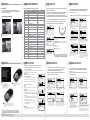
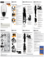
INSTALLATION
INSTALLATION (SURFACE MOUNT)
Camera Parts and ID Setup
Installation Using Surface Mount Bracket
1
1
2
3
2
4
5
Main Body
3
6
4
5
5
7
6
7
Bottom of Main Body
x12 Analog PTZ Outdoor
Quick Start Guide
8
8
9
Version 1.01
9
Surface Mount
Bracket
10
This equipment has been tested and found to comply with the limits for a Class A digital device, pursuant to part 15 of the FCC Rules.
These limits are designed to provide reasonable protection against harmful interference when the equipment is operated in a
commercial environment. This equipment generates, uses, and can radiate radio frequency energy and, if not installed and used in
accordance with the instruction manual, may cause harmful interference to radio communications. Operation of this equipment in a
residential area is likely to cause harmful interference in which case the user will be required to correct the interferenece at his own
expense.
10
Dome Cover
- Protects the camera module from outside environment.
- Do not detach protection film from the dome cover
before finishing all installation to protect
dome cover from scratches or dust.
Lockup Screw
Fixes main body to the surface mount bracket.
Fan
Fan for temperature control.
BNC Video Cable
Main video output cable.
9P Terminal Block Slot
9P terminal block that is connected with cables is
inserted in this slot.
LED & Reset Button
LED for active(yellow light), power(red light) status
and Reset button for reset camera.
ID Setup Switch
Specify the camera ID.
The ID number of the camera is set using binary
numbers.
- If you want to control a certain camera, you must
match the camera ID with ‘CAM ID’ setting of DVR or
keyboard controller.
- The range of Camera ID is 0~255.
- All cameras have a factory default Camera ID of 1.
- Camera ID will be effective without having to reboot
the camera.
¾” Pipe Mounting Hole
- This is used to pass the cables to the cameras.
- When water protection is needed, connect the ¾” pipe
through this hole, then pass the cables through the
pipe.
Mounting Hole (x4)
This is used to attach the surface mount bracket to the
ceiling.
Surface Mount Bracket
The camera’s main body protects the camera’s wires.
This part is required when installing the camera with
an Indoor Accessory.
Drilling the Hole
on the Ceiling
1
2
Rubber Gasket
2
Installation Using Sunshield Dome*
1
Ceiling Mount
Option
Disassemble the main body with the
surface mount before installation the
camera.
Template Sheet
1
Pass cables through
3/4” holes & mount
Bracket.
3
2
Drilling 4 Holes on the Ceiling
Using provided template sheet, drill a hole
(30mm diameter) on the ceiling panel to
pass cables.
Fixing the Surface Mount Bracket
Pass the cables through the ¾” pipe hole,
and screw the surface mount bracket to the
ceiling.
Rubber Gasket
- Before installing the gasket, the hole in the
center is to be cut by knife when only necessary.
3
4
4
4
5
!
Installation Using Ceiling / Wall Mount Bracket*
Alarm Output
- It connects to the alarm lights, siren or lamps,
and it is activated according to the OSD menu
setting.
- There are 1 Alarm Output and it is relay
contact type. Therefore, you do not have to
care about polarity, AC/DC, and isolations
between channels. Care must be taken for the
power capacity of relay contact type.
- The sensor types are normal open and
normal close.
1
Power Input Slot
Alarm Output Slot
Alarm Input/Sensor Slot
DWC-P12CM
Indoor Ceiling Mount*
1
RS-485 Slot
Main Body + Surface Mount Bracket
2
Alarm Input/Sensor
- It connects to IR sensor, IrDA sensor or door
switch. If the sensor is activated, it can activate
to move camera to the specific angle and to
connect the alarm device.
- A cable of the sensor should connect to input
1 or 2, and the other should be connected to
‘COM’ slot.
- The sensor types are normal open and
normal close.
2
COM
DWC-P12CMS
Sunshield Ceiling Mount
3
(Not Included)
2
1
3
(Not Included)
DWC-P39POLM
Pole Mount
(Not Included)
5
6
COM
Screw & Plastic Anchor-4pcs
4
Torx Wrench
DWC-P12WMS
Sunshield Wall Mount
(Not Included)
DWC-P39CNM
Corner Mount
7
RS-485 Communication (Keyboard Controller/
DVR)
For PTZ control, connect this line to keyboard
and DVR.
To control multiple cameras at the same time,
RS-485 communication lines of them are
connected in parallel as shown below.
Power
- Please check the correct rated power.
- The rated power is marked on the bottom of
the camera.
(Not Included)
4
Keyboard
Controller/DVR
2
09 1 9 2 0 1 2
Wall Mount Option
Fixing the Sunshield Dome
Pass the cables through the hole of the
Sunshield Dome. Screw the Sunshield Dome to
the ceiling mount bracket.
Connecting the Cables to the Terminal Block
Connect the cables to the terminal block and
then put the terminal block in the slot of the
main body.
Connecting the Terminal Block
Put the terminal block connected to the
cables in the slot of the main body.
Fixing the Main Body
Screw the main body to the surface mount
bracket by screwing 4 lock-up screws.
Detaching the Protection Film
Detach the protection film from the dome
cover after finishing all installation.
Accessories are optional and sold separately.
7
Check Points before Operation
1. Before power is applied, please check the cables carefully.
2. The camera ID of the controller must be identical to that of the camera to be
controlled. The camera ID can be check in the system information of OSD menu.
Rubber
Gasket
3. If your controller supports multi-protocols, the protocol must be changed to
match to that of the camera.
2
1
8
2
Rubber
Gasket
3
3
4
5
4
5
7
4
Fixing the Ceiling Mount Bracket
1. Drill a hole (20mm diameter) on the pipe of
the bracket to pass the cables.
2. On the fixed anchor bolts, attach the
rubber gasket and screw the ceiling
mount bracket.
First Time Bootup and Initial Testing
Rubber Gasket
~
Accessories are optional and sold separately.
Disassemble the main body with the surface
mount before installation the camera.
Drilling a Hole on the Ceiling and Fixing
the Anchor Bolts
To install the ceiling mount bracket, drill four
holes (6mm diameter/50mm depth) on the
ceiling and insert the anchor bolts into the
hole.
INSTALLATION
1
1
6
7
3
Camera 1 Camera 2 Camera n
TEL: (866) 446-3595
www.Digital-Watchdog.com / [email protected]
Technical Support Hours: Monday-Friday 8:30AM to 8:00PM EST
Ceiling Mount Option
6
Thank you for purchasing Digital Watchdog’s Super Speed Dome PTZ Outdoor Dome Camera.
Before installing the camera, please verify your model and read this guide carefully.
!
6
7
5
Terminal Block Connections
DWC-P12WM
Indoor Wall Mount
5
7
The following items are included with the PTZ camera
9P Terminal Block
6
Detaching the Protection Film
Detach the protection film from the dome
cover after finishing all installation.
3
Rubber Gasket
5
Fixing the Main Body
Screw the main body to the surface mount
bracket by screwing 4 lock-up screws.
INSTALLATION (INDOOR)
Rubber Gasket
2
3
INSTALLATION
Quick Manual
1
Connecting the Cables and the Terminal Block
Connect the cables to the terminal block and
then put the terminal block in the slot of the
main body.
PREPARATION
Manual CD
2
3
4
Wall Mount
Option
Rubber
Gasket
5
To disconnect power from the mains, pull out the mains cord plug.
When install the product, ensure that the plug is easily accessible.
Template Sheet
INSTALLATION (OUTDOOR)
!
Disassemble the main body with the
surface mount before installation the camera.
Drilling 4 Holes on the Ceiling/ Wall and Fixing
the Anchor Bolts
To install the ceiling mount bracket, drill four
holes (6mm diameter/50mm depth) on the
ceiling and insert the anchor bolts into the
hole.
Fixing the Ceiling Mount Bracket
1. Drill a hole (20mm diameter) on the pipe of
the bracket to pass the cables.
2. On the fixed anchor bolts, attach the rubber
gasket and screw the ceiling mount bracket.
Fixing the Surface Mount Bracket
Pass the cables through the hole of the surface
mount bracket, screw the surface mount
bracket to the ceiling mount bracket.
Connecting the Cables to the Terminal Block
Connect the cables to the terminal block and
then put the terminal block in the slot of the
main body.
Connecting the Terminal Block
Put the terminal block connected to the cables
in the slot of the main body.
Fixing the Main Body
Screw the main body to the surface mount
bracket by screwing 4 lock-up screws.
Detaching the Protection Film
Detach the protection film from the dome
cover after finishing all installation.
4. If you changed camera protocol by changing DIP switch, the change will be
effective after you reboot the camera.
5. Since the operation method can be different for each controller available, refer
to the manual for your controller if camera cannot be controlled properly.
9
Preset and Pattern Function Pre-check
Check how to operate preset, pattern, scan and group
function with keyboard controller/DVR in advance to operate
camera function using them.
(Refer to system keyboard manual)
Start OSD Menu
Using the OSD menu, preset, pattern, scan, group and alarm
input function can be configured for each application.
Enter ‘Preset key + 95’.
Auto Calibration
If the camera is continuously subjected to very
high temperatures (over 50°C or 122°F) for a long
period, the camera can lose focus and produce
blurry images. In this case, it is recommended to
turn on AUTO CALIBRATION by running preset 165.
If you execute AUTO CALIBRATION, the camera
will calibrate its focus for 10 seconds every 24
hours. To turn OFF this function, please run
preset 166.
Accessories are optional and sold separately.
6
8
OSD MENU (FOR DW’S VMAX, VMAX480 & VMAX Flex)
Preset 95
Some preset numbers are reserved to special functions.
Preset 95 is reserved for starting the camera’s OSD menu.
For a complete list of all the reserved presets, see the PTZ12X’s
complete manual or page 19.
1
Select Full Screen view on the selected PTZ camera
2
Right-Click the screen & Select ‘PTZ’
4
3
By using the scan function, you can make the camera to move between 2
preset positions repeatedly.
When the scan function runs, the camera moves from the preset assigned
as the 1st point to the preset assigned as the 2nd point in Clockwise
direction. Then the camera moves from the preset assigned as the 2nd
point to the preset assigned as the 1st point in Counterclockwise direction.
Preset #
Function
On/Off
95
131~134
141~148
151~158
161~164
Set key +
161~164
165
166
167
Set key +
167
170
171
174
175
176
177
178
179
190
191
192
193
194
200
201
Enters Into OSD Menu
Pattern Function 1 ~ 4
Scan Function 1 ~ 8
Group Function 1 ~ 8
Relay 1~ 4 Output
Relay 1~ 4 Output
ON
ON
ON
ON
OFF
ON
Auto Calibration
Auto Calibration
Zoom Proportional Jog
Zoom Proportional Jog
ON
OFF
ON
OFF
BLC Mode
BLC Mode
Camera Focus Mode
Camera Focus Mode
Camera Focus Mode
Day & Night Mode
Day & Night Mode
Day & Night Mode
OSD Display Mode
OSD Display mMode
OSD Display Mode
All Privacy Mask display
All PrivacyMask display
Digital zoom
Digital zoom
OFF
HIGH
AUTO
MANUAL
SEMI-AUTO
AUTO
NIGHT
DAY
AUTO (except privacy mask)
OFF (except privacy mask)
ON (except privacy mask)
OFF
ON
ON
OFF
Accessing the OSD Menu
Right-Click the screen again, & select ‘Preset’
Enter 95 to access the OSD menu
In case that the preset assigned as the 1st point is same as the preset
assigned as the 2nd point, the camera turns on its axis by 360° in CW
direction and then it turns on its axis by 360° in CCW direction.
FUNCTION SETUP
- - - - - - - - - - - - - - - - - - - <PRESET SETUP>
<SCAN SETUP>
<PATTERN SETUP>
<GROUP SETUP>
<SCHEDULE SETUP>
A preset is a pre-defined position for the camera. Setup 127
presets, excluding 95, which is reserved for menu access.
PRESET SETUP- UNIDENTIFIED.
If a selected preset is already defined, camera will move to the pre-defined position. If a
selected preset is not defined, ‘UNDEFINED’ will appear.
<EDIT SCENE>
FUNCTION SETUP
Redefine the current preset scene position(i.e. PTZ).
- - - - - - - - - - - - - - - - - - - - - - - - - - 1. Using joystick, move camera to the desired position.
forward to save, or backwards to cancel all changes.
2
6
To move to a sub-menu
Once you have selected the sub-menu
you want to enter, scroll the mouse’s
wheel forward.
2
3
2
7
!
To exit a sub-menu
When you have completed all desired modifications,
scroll the mouse’s wheel forward to save changes,
or backwards to return to the Root menu and cancel
all changes
- - - - - - - - - - - - - - - - - - - - - - - - - - -
SCAN SPEED
CLEAR SCAN
1
NOT USED
NOT USED
SCAN NO.
Selects the scan number to edit. If a selected scan has not
defined, ‘NOT USED’ is displayed in 1st position and
2nd position.
1ST POS. / 2 ND POS.
Set up the 2 position for scan function. If a selected preset is
not defined, ‘UNDEFINED’ will be displayed as shown
below.
30/SEC
CANCEL
BACK
EXIT
SCAN SPEED
Sets the scan speed.
4
PRESET SETUP- DEFINED PRESET
<LABEL>
Edit a label for the selected preset. Max. 10 characters.
1
PRESET 1
NOT USED
UNDEFINED
SCAN SPEED 30/SEC
SCAN
NO.
1ST POS.
2ND POS.
!
CAM ADJUST
- WB and AE can be set up independently for each preset.
- GENERAL: WB/ AE settings will follow the camera’s setup for
both options under ‘ROOT MENU>CAMERA SETUP’ menu.
- SPECIAL:
- Each special WB/AE value will the activated when the
camera runs the selected preset. During jog operation,
general WB/AE value will be applied.
- If ‘SPECIAL’ is selected, any changes made to the general
camera settings for WB and AE will not apply to the
preset’s WB/ AE settings.
ALARM OUT
Relay output can be linked with a specific preset run.
‘ - ‘means off, ‘1’ means on.
PRESET SETUP
PRESET NO.
<EDIT SCENE>
1
UNDEFINED
Note: to properly setup a scan for the camera,
be sure to have at least 2 Presets setup..
EDIT SCENE
-PRESET1
- - - - - - - - - - - - - - - - - - - - - - - - - - -
Pattern function is when a camera memorizes the path (mostly
curve path) created by a joystick controller and revives the
path exactly as it memorized for an assigned time.
1
<PRESET SETUP>
<SCAN SETUP>
<PATTERN SETUP>
<GROUP SETUP>
<SCHEDULE SETUP>
1
UNDEFINED
CLEAR PATTERN CANCEL
<EDIT PATTERN>
BACK
EXIT
- - - - - - - - - - - - - - - - - - - - - - - - - - -
- - - - - - - - - - - - - - - - - - - - - - - - - - -
- - - - - - - - - - - - - - - - - - - - - - - - - - -
BACK
EXIT
EDIT PATTERN
FUNCTION SETUP
PATTERN SETUP
PATTERN NO.
BACK
EXIT
Select the pattern number you wish to setup.
If a selected pattern is not defined, ‘UNDEFINED’
will be displayed as shown.
EDIT PATTERN
10
In the Root Menu,
go to Function Setup> Schedule Setup
PRESET SETUP
PRESET NO.
1
- - - - - - - - - - - - - - - - - - - - - - - - - - -
<EDIT SCENE>
2 <LABEL>
3 CLR PRESET
CAM ADJUST
4 ALARM OUT
CANCEL
GENERAL
-
MOVE TO START POSITION
[NEAR:START/ FAR:CANCEL]
0/0/x1/E
By using joystick, move the camera
to the start position with appropriate
zoom. Using the mouse’s wheel,
scroll near to save and start recording,
or far to cancel all changes.
SCHEDULE SETUP
[NEAR:SAVE / FAR:DELETE]
0/0/x1/E
Move the camera using the Joystick controller
or the computer mouse in the desired pattern.
The total memory size is displayed in the form
of a bar. Using the mouse’s wheel, scroll bear to save
patterm, or scroll far to cancel all changes.
BACK
EXIT
12
EDIT GROUP
1
- - - - - - - - - - - - - - - - - - - - - - - - - - -
NO. ACTION NO. DWELL OPT
1 NONE
2 NONE
3 NONE
4 NONE
5 NONE
- - - - - - - - - - - - - - - - - - - - - - - - - SAVE
[ :MOVE CURSOR]
CANCEL [ : CHANGE VAL.]
- - - - - - - - - - - - - - - - - - - - - - - - - -
Using the mouse, click on the top and bottom of the
screen to scrol down the options. Select from
Preset, Pattern, Scan. Click on the right side of the
screen to save selection and move to the next tab to
the right.
EDIT GROUP
1
- - - - - - - - - - - - - - - - - - - - - - - - - - -
NO. ACTION NO. DWELL OPT
- - - - - - - - - - - - - - - - - - - - - - - - - 1 PATTERN 1 00:03 1
2 NONE
3 NONE
4 NONE
5 NONE
- - - - - - - - - - - - - - - - - - - - - - - - - [NEAR:EDIT ACT]
SAVE
CANCEL [FAR :EDIT END]
When you finish setting up an ACTION,
press Near or Enter key to one-upper-level
menu. Move to the next action and repeat setup
as necessary. When you have completed entering
all desired actions, scrol near to save changes,
or far to cancel all changes.
15
SCHEDULE SETUP
- - - - - - - - - - - - - - - - - - - - - - - - - - -
MASTER ENABLE
OFF
DAY TIME ACT NO ON
1 UNDEFINED
2 UNDEFINED
3 UNDEFINED
4 UNDEFINED
5 UNDEFINED
6 UNDEFINED
7 UNDEFINED
BACK
Select the schedule you wish to modify, and using the
mouse’s wheel, scroll near to enter Edit mode.
1
- - - - - - - - - - - - - - - - - - - - - - - - - - -
MOVE TO TARGET POSITION
[NEAR:SELECT/FAR:CANCEL]
0/0/x1/E
Select the Group you wish to modify. If a group
is not defined, ‘UNDEFINED’ will be displayed
as shown.
The schedule function allows running an appropriate function
like preset, scan, pattern, group, home move at designated
day and time.
To setup a schedule, at leaset 1 Preset, 1 scan, 1 pattern, and 1
group should be setup.
4 patterns are available and maximum 1000 communication
commands can be stored in a pattern.
<PRESET SETUP>
<SCAN SETUP>
<PATTERN SETUP>
<GROUP SETUP>
<SCHEDULE SETUP>
1
UNDEFINED
CANCEL
SCHEDULE SETUP
Please consult the manual for further instructions on how
to use a computer mouse to operate the OSD Menu
TEL: (866) 446-3595
www.Digital-Watchdog.com / [email protected]
Technical Support Hours: Monday-Friday 8:30AM to 8:00PM EST
Using the mouse, continue editing the desired
information. Enter the action’s number, Dwell
time between each action, and the numebr of
repetitions under OPT.
13
In the Root Menu,
go to Function Setup> Pattern Setup
BACK
EXIT
1
NO. ACTION NO. DWELL OPT
- - - - - - - - - - - - - - - - - - - - - - - - - 1 PATTERN 1 00:03 1
2 NONE
3 NONE
4 NONE
5 NONE
- - - - - - - - - - - - - - - - - - - - - - - - - SAVE
[ :MOVE CURSOR]
CANCEL [ : CHANGE VAL.]
- - - - - - - - - - - - - - - - - - - - - - - - - - -
- - - - - - - - - - - - - - - - - - - - - - - - - - -
1
1
- - - - - - - - - - - - - - - - - - - - - - - - - - -
SCAN SETUP
- - - - - - - - - - - - - -
BACK
EXIT
Select the first action in the group.
Click with the mouse on the right side
of the screen to enter edit mode.
EDIT GROUP
GROUP SETUP
- - - - - - - - - - - - GROUP NO.
CLEAR GROUP
<EDIT GROUP>
NO. ACTION NO. DWELL OPT
- - - - - - - - - - - - - - - - - - - - - - - - - 1 NONE
2 NONE
3 NONE
4 NONE
5 NONE
- - - - - - - - - - - - - - - - - - - - - - - - - SAVE
[NEAR:EDIT ACT]
CANCEL [FAR :EDIT END]
CLEAR SCAN
Deletes the current scan data.
- - - - - - - - - - - - - - - - - - - - - - - - - - -
BACK
EXIT
>
5 Using mouse, click on area of the screen
labeled:
UP: to scroll up the menu
DOWN: to scroll down the menu
Left: Vertically move from one edit tab
to the one to its left
RIGHT: Vertically move from one
edit tab to the one to its right.
SCAN SETUP
SCAN
NO.
1ST POS.
2ND POS.
- - - - - - -
BACK
EXIT
1. CW direction
FUNCTION SETUP
2. Using your USB mouse, scroll the mouse’s wheel
>
Down
FUNCTION SETUP
- - - - - - - - - - - - - - - - - - - <PRESET SETUP>
<SCAN SETUP>
<PATTERN SETUP>
<GROUP SETUP>
<SCHEDULE SETUP>
2. CCW direction
<PRESET SETUP>
<SCAN SETUP>
<PATTERN SETUP>
<GROUP SETUP>
<SCHEDULE SETUP>
TO EDIT THE PRESET’S SCENE
>
1
Right
To setup a group, at leaset 1 preset, 1 scan, 1 pattern must be setup.
- - - - - - - - - - - - - - - - - - - - - - - - - - -
BACK
EXIT
PATTERN SETUP
PRESET SETUP
Up
and/or scans. Maximum 8 group can be stored. Each group can
have max 20 actions.
In the Root Menu,
go to Function Setup> Group Setup
- - - - - - -
11
1
Left
1st POS.
2nd POS.
The group function allows you to run sequence of presets, pattern,
EDIT GROUP
9
OSD MENU (CONTROL THROUGH THE DVR)
GROUP SETUP
SCAN SETUP
RESERVED PRESETS
14
MASTER ENABLE
OFF
DAY TIME ACT NO ON
OFF
1 ALL 00:00 HOM
2 UNDEFINED
3 UNDEFINED
4 UNDEFINED
5 UNDEFINED
6 UNDEFINED
7 UNDEFINED
BACK
Select the days of the week you wish
to set for this schedule. Select from
All, WKD (Every day except Saturday
and Sunday), or Sun~Sat. When you are
done, click on the right corner of the screen
to move to the next edit section.
SCHEDULE SETUP
- - - - - - - - - - - - - - - - - - - - - - - - - - -
MASTER ENABLE
ON
DAY TIME ACT NO ON
ON
1 MON 01:20 HOM
2 WED 07:00 PRS 12 ON
3 THU 11:4 0 SCN 3 ON
4 ALL 12:00 SCN 1 ON
5 UNDEFINED
6 UNDEFINED
7 UNDEFINED
BACK
Continue to edit the time of the day, the act you wish
to run at that time (home, preset, pattern, scan, group),
select the act no for a specific action. When you are
complete, to enable the schedule select ON. Using
the mouse’s wheel, scroll near to save changes or far
to cancel.
To enable the camera to start running the schedules,
make sure the specific schedule is enabled, and
also MASTER ENABLE on the top of the screen is ON.
16