1
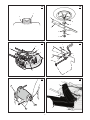
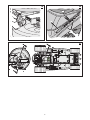
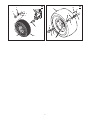
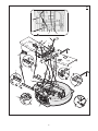
M10/30
HERITAGE TRACTOR
CODE 134E
INSTRUCTION BOOK
CAUTION: Read and
follow all instructions.
Code
134E
Serial No.
290000001
Issue 02/2009
Part No. 111-3047 (Rev A)
1742440
Revision A
2
1
2
3
8
1
4
7 (25x3)
2
5
6 (17x146)
4 (17x47)
1
1
5 (1001054)
3
2
6
1
4
3
6 (2x82)
4
3
2
6 (2x82)
1
8
4
6
7 (14x79)
5
5
4
3
7
9
2
6
5
1
8
9
1
7
3
7
8
6
2
B
A
9
10
11
12
7
1
1
5
3
2
3
4
14
13
1
2
7
6
5
1
2
4
3
16
15
1
2
3
3
1
4
2
5
6
4
7
18
17
1
1
3
3
9/16
2
2
3
5
20
19
1
4
5
3
21
6
22
5
6
23
10
12
11
4
7
4
9
8
6
3
7
2
13
1
2
7
21
7
10
8
10
1
6
11
4
3
3
7
9
4
5
5
8
25
1
2
3
6
5
4
MAX+ 90N MAX+ 150N
9
8
7
10
11
13
12
26
1
10
2
4
3
11
12
5
6
7
13
14
15
8
9
27
25x3
17x146
327349
1001054
17x47
2x82
14x79
9
LIMITED WARRANTY
Hayter Limited warrants to the original user / purchaser that this unit shall be free from defects in material and
workmanship under normal use and service for a period of three years from the date of purchase. The manufacturer of the engine furnish their own warranty and services are provided through their authorised network (Refer
to “Engine Warranty Statement”). To qualify for the full benefit of the warranty, the warranty registration card must
be returned within 60 days of purchase. Subject to the conditions and exclusions noted in this limited warranty, we
shall at our option, repair or replace any warranted part during the applicable period. If you are in doubt or experience any difficulty, please consult a Hayter Authorised Service Dealer for clarification.
To qualify for the extended warranty (second and third year) of the three year limited warranty, the machine must
have annual services carried out by an Authorised Hayter Service Dealer. These chargeable services should be
carried out within 12 and 24 months of the date of purchase.
Excluded from the extended warranty period are those items which are subject to normal wear and tear e.g. tyres,
wheels, cutterblades, cables, batteries and other consumable wearing parts.
All consumer machines which are fitted with a genuine Hayter friction disc as original equipment, before use, are
covered by a Lifetime Warranty against the engine crankshaft bending. Note: friction washers, blade brake
units and other such devices are not applicable. Only machines fitted with a genuine Hayter friction disc, which
are used in accordance with the recommended operating and maintenance procedures, are covered.
This warranty does not apply to any unit that has been tampered with, altered, misused, abused or used for hire,
and will become invalid if non genuine Hayter parts are fitted. This warranty does not cover minor mechanical
adjustments unless they are due to defective materials or workmanship. Consult the Owner’s Handbook or a
Hayter Authorised Service Dealer for assistance when making these adjustments.
A warranty period of 90 days applies to machines used for commercial purposes.
To make a warranty claim, return the unit to a Hayter authorised dealer along with proof of purchase stating the
machine serial number and date of purchase. The service receipt(s) or this Owner’s Handbook with the 1st/2nd
year service boxes fully completed, must be produced as proof of entitlement to the extended warranty period.
Subject to the conditions and exclusions in this limited warranty, the authorised dealer will, at our option, repair or
replace any warranted part within the duration of the warranty period.
This limited warranty gives you specific legal rights and is in addition to any statutory rights to which you may be
entitled and your statutory rights are not affected by this warranty. If you need additional information concerning
this written warranty, or assistance in obtaining services, please write to:
HAYTER LIMITED, Service Department, Spellbrook, Bishop’s Stortford, Hertfordshire CM23 4BU.
1st
Year
Service
Record
2nd
Year
Service
Record
Date . . . . . . . . . . . . . . . . . . . . . . . . . . . . . . . . . . . . . . . . .
Signed . . . . . . . . . . . . . . . . . . . . . . . . . . . . . . . . . . . . . . . .
Date . . . . . . . . . . . . . . . . . . . . . . . . . . . . . . . . . . . . . . . . .
Signed . . . . . . . . . . . . . . . . . . . . . . . . . . . . . . . . . . . . . . . .
10
CONTENTS
LIMITED WARRANTY
10
INTERNATIONAL PICTORIALS
11
OWNER’S INFORMATION
12
SAFE OPERATION PRACTICES
12
ASSEMBLY
13
OPERATION
14
MAINTENANCE CHART
17
MAINTENANCE
17
TROUBLESHOOTING CHART
20
INTERNATIONAL PICTORIALS
IMPORTANT: The following pictorials are
located on your unit or on literature supplied
with the product. Before you operate the
unit, learn and understand the purpose for
each pictorial.
NOTE: Illustrations and pictorials begin on
page 2.
5
DANGER: Keep People, Especially
Children, Away From Unit.
Control And Operating Pictorials
6
DANGER: No Step.
1
Engine Start
7
DANGER: Keep Feet And Hands Away
From Rotating Blade.
2
Lights
8
DANGER: Disconnect Spark Plug Wire
Before Servicing Unit.
3
Engine Run
4
Engine Stop
5
Engine Run
6
Brake
7
Parking Brake
8
Clutch
9
Slow
9
Safety Warning Pictorials (Figure 25)
1
2
3
4
WARNING
IMPORTANT: Read Owner’s Manual Before
Operating This Machine.
WARNING: Thrown Objects. Keep
Bystanders Away. Read User Instructions
Before Operating This Machine.
WARNING: Hot Surface.
10 WARNING: Use Caution When Connecting
Or Disconnecting Accessories.
11 WARNING: Crushed Fingers.
12 IMPORTANT: Follow Instructions In Owner’s
Manual To Level The Deck.
13 WARNING: Stay Clear Of Mower Blade As
Long As Engine Is Running.
WARNING: Do Not Use This Machine On
Slopes Greater Than 10 Degrees.
(Figure 26)
10 Fast
11 Choke
12 Oil
13 Blade Rotation Control
14 Raise
15 Fuel
11
OWNER’S INFORMATION
Know your product: If you understand the unit
and how the unit operates, you will get the best
performance. As you read this manual, compare
the illustrations to the unit. Learn the location
and the function of the controls. To help prevent
an accident, follow the operating instructions
and the safety rules. Keep this manual for future
reference.
1.
2.
3.
WARNING: Look for this symbol to indicate
important safety precautions. This symbol
indicates: “Attention! Become Alert! Your
Safety Is At Risk.”
Responsibility Of The Owner
WARNING: This cutting machine is
capable of amputating hands and feet
and throwing objects. Failure to
observe the following safety instructions
could result in serious injury or death to the
operator or bystanders.
4.
5.
The responsibility of the owner is to
follow the instructions below.
SAFE OPERATION PRACTICES
For Ride-On (Riding)
Rotary Mower Machines
Training
1.
2.
3.
4.
5.
6.
Read the instructions carefully. Be familiar
with the controls and the proper use of the
equipment.
Never allow children or people unfamiliar
with these instructions to use the mower.
Local regulations may restrict the age of the
operator.
Never mow while people, especially
children, or pets are nearby.
Keep in mind that the operator or user is
responsible for accidents or hazards
occurring to other people or their property.
Do not carry passengers.
All drivers should seek and obtain
professional and practical instruction. Such
instruction should emphasize:
a. the need for care and concentration
when working with ride-on machines;
b. control of a ride-on machine sliding on a
slope will not be regained by the
application of the brake. The main
reasons for loss of control are:
•
insufficient wheel grip;
•
being driven too fast;
•
inadequate braking;
•
the type of machine is unsuitable
for its task;
•
lack of awareness of the effect of
ground conditions, especially
slopes;
•
incorrect hitching and load
distribution.
8.
Preparation
6.
While mowing, always wear substantial
footwear and long trousers. Do not operate
the equipment when barefoot or wearing
open sandals.
Thoroughly inspect the area where the
equipment is to be used and remove all
objects which may be thrown by the
machine.
WARNING - Petrol is highly flammable.
a. Store fuel in containers specifically
designed for this purpose.
b. Refuel outdoors only and do not smoke
while refuelling.
c. Add fuel before starting the engine.
Never remove the cap of the fuel tank
or add petrol while the engine is running
or when the engine is hot.
d. If petrol is spilled, do not attempt to start
the engine but move the machine away
from the area of spillage and avoid
creating any source of ignition until
petrol vapours have dissipated.
e. Replace all fuel tanks and container
caps securely.
Replace faulty silencers.
Before using, always visually inspect to see
that the blades, blade bolts and cutter
assembly are not worn or damaged.
Replace worn or damaged blades and bolts
in sets to preserve balance.
On multi-blade machines, take care as
rotating one blade can cause other blades
to rotate.
Operation
1.
2.
3.
4.
5.
6.
7.
Do not operate the engine in a confined
space where dangerous carbon monoxide
fumes can collect.
Mow only in daylight or in good artificial
light.
Before attempting to start the engine,
disengage all blade attachment clutches
and shift into neutral.
Do not use on slopes of more than 10
degrees.
Remember there is no such thing as a
“safe” slope. Travel on grass slopes
requires particular care. To guard against
overturning:
a. do not stop or start suddenly when
going up or downhill;
b. engage clutch slowly, always keep
machine in gear, especially when
travelling downhill;
c. machine speeds should be kept low on
slopes and during tight turns;
d. stay alert for humps and hollows and
other hidden hazards;
e. never mow across the face of the slope,
unless the mower is designed for this
purpose.
Use care when pulling loads or using heavy
equipment.
a. Use only approved drawbar hitch
points.
b. Limit loads to those you can safely
control.
c. Do not turn sharply. Use care when
reversing.
d. Use counterweight(s) or wheel weights
when suggested in the Instruction Book.
Watch out for traffic when crossing or near
roadways.
12
9.
10.
11.
12.
13.
14.
15.
16.
17.
18.
Stop the blades rotating before crossing
surfaces other than grass.
When using any attachments, never direct
discharge of material toward bystanders nor
allow anyone near the machine while in
operation.
Never operate the mower with defective
guards or shields, or without safety
protective devices in place.
Do not change the engine governor settings
or overspeed the engine. Operating an
engine at excessive speed may increase
the hazard of personal injury.
Before leaving the operator’s position
a. disengage the power take-off and lower
the attachments;
b. change into neutral and set the parking
brake;
c. stop the engine and remove the key.
Disengage drive to attachments, stop the
engine, and disconnect the spark plug
wire(s) or remove the ignition key
a. before cleaning blockages or
unclogging chute;
b. before checking, cleaning or working on
the mower;
c. after striking a foreign object. Inspect
the mower for damage and make
repairs before restarting and operating
the equipment;
d. if the machine starts to vibrate
abnormally (check immediately).
Disengage drive to attachments when
transporting or not in use.
Stop the engine and disengage drive to
attachment
a. before refuelling;
b. before removing the grass catcher;
c. before making height adjustment unless
adjustment can be made from the
operator’s position.
Reduce the throttle setting during engine
run-out and, if the engine is provided with a
shut-off valve, turn the fuel off at the
conclusion of mowing.
Before and when backing, look behind and
down for small children.
Use extra care when approaching blind
corners, shrubs, trees or other objects that
may obscure vision.
Maintenance and Storage
1.
2.
3.
4.
5.
6.
7.
8.
9.
On multi-blade machines, take care as
rotating one blade can cause other blades
to rotate.
When machine is to be parked, stored or left
unattended, lower the cutting means unless
a positive mechanical lock is used.
Keep all nuts, bolts, and screws tight to be
sure the equipment is in safe working
condition.
Never store the equipment with petrol in the
tank inside a building where fumes may
reach an open flame or spark.
Allow the engine to cool before storing in
any enclosure.
To reduce the fire hazard, keep the engine,
silencer, battery compartment and petrol
storage area free of grass, leaves, or
excessive grease.
Check the grass catcher frequently for wear
or deterioration.
Replace worn or damaged parts for safety.
If the fuel tank has to be drained, this should
be done outdoors.
ASSEMBLY
4.
All fasteners are in the parts bag. Do not discard
any parts or material until the unit is assembled.
WARNING: Before doing any
assembly or maintenance to the
mower, remove the wire from the
spark plug.
NOTE: In this instruction book, left and right
describe the location of a part with the
operator on the seat.
NOTE: Illustrations and pictorials begin on
page 2.
NOTE: To assemble the following loose
parts, use the fasteners shown at full size in
Figure 27.
How To Install The Seat (Figure 1)
1.
2.
3.
4.
Carefully remove the plastic bag from the
seat (1).
Raise the seat support (2) and secure in
the UP position with the seat support rod
(6).
Align the holes in the seat (1) to the holes in
the seat support (2). Fasten the seat (1) to
the seat support (2) with the fasteners (4)
and (5).
Check the operating position of the seat (1).
If the seat (1) needs to be adjusted, loosen
the two wing bolts (5). Slide the seat (1)
forward or backward along the seat
adjusting holes (3). Tighten the wing bolts
(5).
How To Assemble The Steering Wheel
(Figure 2)
1.
2.
3.
4.
5.
Make sure the front wheels point forward.
Slide the tube (1) into the console (2).
Make sure the end of the tube (1) fits over
the steering bushing (3).
Attach the steering wheel (4) to the
steering post (5) with screw (7) and
washer (6).
Slide the steering wheel (4) and steering
post (5) into the tube (1) and console (2).
Push on the steering wheel (4). The
steering post (5) will lock onto the pinion
gear. Pull on the steering wheel (4). Make
sure that the steering post (5) is locked in
place.
Some models have an optional insert (8) in
the parts bag. Attach the insert (8) to the
centre of the steering wheel (4).
Maintenance Free Battery (Figure 3)
IMPORTANT: Before you attach the battery
cables to the battery, check the battery date.
The battery date tells if the battery must be
charged.
1.
2.
3.
Raise the seat support and secure in the UP
position with the seat support rod.
Check the top of the battery (1) for the
location of the battery date.
If the battery (1) is put into service before
the battery date, the battery cables can be
attached without charging the battery (1).
See “How To Install The Battery Cables”.
If the battery (1) is put into service after the
battery date, the battery (1) must be
charged. See “How To Charge The
Maintenance Free Battery”.
How To Charge The Battery (Figure 3)
WARNING: When you charge the
battery, do not smoke. Keep the
battery away from any sparks. The
fumes from the battery acid can cause an
explosion.
1.
2.
3.
4.
5.
To disconnect the battery retainer (2) from
the battery tray (3), push in on the lower
end of the battery retainer (2).
Remove the battery (1) from the right side
of the unit.
Remove the protective cap from the battery
terminal.
Use a 12 volt battery charger to charge the
battery (1). Charge at a rate of 6 amperes
for one hour. If you do not have a battery
charger, have an authorized service centre
charge the battery.
Install the battery (1) and secure with the
battery retainer (2). Make sure the
positive (+) terminal (4) is on the right
side.
How To Install The Battery Cables
(Figure 3)
WARNING: To prevent sparks, fasten
the red cable to the positive (+)
terminal before you connect the black
cable.
1.
2.
3.
Remove the protective cap from the battery
terminal.
Fasten the red cable (5) and terminal
cover (9) to the positive (+) terminal (4)
with the fasteners (6) and (7).
Fasten the black cable (8) to the negative
(-) terminal with the fasteners (6) and (7).
Check The Tires
Check the air pressure in the tires. Tires with too
much air pressure will cause the unit to ride
rough. Also, the wrong air pressure will keep the
mower housing from cutting level. The correct
air pressure is: Front Tires 0,97 BAR (14 PSI),
Rear Tires 0,69 BAR (10 PSI). The Tires were
over inflated for shipment.
Check The Level Of The Mower Housing
Make sure the level of cut is still correct. After
you mow a short distance, look at the area that
was cut. If the mower housing does not cut
level, see the instructions on “How To Level The
Mower Housing” in the Maintenance section of
this instruction book.
How To Prepare The Engine
NOTE: The engine was shipped from the
factory filled with oil. Check the level of the
oil. Add oil as needed.
See the engine manufacturer’s instructions for
the type of petrol and oil to use. Before you use
the unit, read the information on safety,
operation, maintenance, and storage.
13
WARNING: Follow the engine
manufacturer’s instructions for the
type of petrol and oil to use. Always
use a safety petrol container. Do not smoke
when adding petrol to the engine. When
inside an enclosure, do not fill with petrol.
Before you add petrol, stop the engine. Let
the engine cool for several minutes.
Important! Before You Start Mowing
❐ Check the engine oil.
❐ Fill the fuel tank with petrol.
❐ Check the level of the mower
housing.
❐ Check the air pressure of the tyres.
❐ Attach the battery cables.
Final Assembly
1.
2.
Check all fasteners. Make sure all fasteners
are properly installed and are tight.
Check installation. Make sure all parts are
correctly installed.
WARNING: Make sure that the grass
bagger is properly assembled and
correctly installed. The Grass Bagger
must only be used when fully assembled and
correctly installed.
OPERATION
NOTE: Illustrations and pictorials begin on
page 2.
Location Of Controls (Figure 4)
Blade Rotation Control (1): Use the blade
rotation control to start and stop the rotation of
the blade.
3.
4.
blade in the ENGAGE position (9).
To stop the blade, move the blade rotation
control (1) to the DISENGAGE position
(8). Before you leave the operator’s
position, make sure the blade(s) has
stopped rotating.
Before you ride the unit across a sidewalk
or a road, move the blade rotation control
(1) to the DISENGAGE position.
Clutch / Brake Pedal (2): The pedal has two
functions. The first function is a clutch. The
second function is a brake.
WARNING: Always keep your hands
and feet away from the blade,
deflector opening, and the mower
housing when the engine runs.
Ignition Switch (3): Use the ignition switch to
start and stop the engine.
How To Engage The Transmission
Speed Control Lever (4): The speed and
direction of travel is controlled by the speed
control lever. Use the speed control lever to
select either forward or reverse.
Lift Lever (5): Use the lift lever to change the
height of cut.
Parking Brake Lever (6): Use the parking
brake lever to engage the brake when you leave
the unit.
Throttle Control Lever (7): Use the throttle
control lever to increase or decrease the speed
of the engine.
Attachments
This unit can use many different attachments. This
unit can pull attachments like a lawn sweeper, a
lawn aerator, or a hopper spreader. This unit can
not use attachments that engage the ground like a
plough, a disk harrow, or a cultivator.
For trailer and pull-behind attachments, the
maximum weight is 90 kg (200 lbs).
Do not operate on a slope that is greater than
10 degrees when using a pull-behind
attachment or trailer.
How To Use The Throttle Control
(Figure 4 and Figure 5)
Use the throttle/choke control (7) to increase
or decrease the speed of the engine.
1. Move the throttle/choke control (7)
completely forward to the CHOKE position
to start a cold engine.
2. The FAST position is marked with a detent.
For normal operation and when using a
grass bagger, move the throttle control to
the FAST position. For maximum charging
of the battery and for a cooler running
engine, operate the engine in the FAST
position.
3. The engine governor is set at the factory for
maximum performance. Do not adjust the
governor to increase the speed of the
engine.
How To Use The Blade Rotation Control
(Figure 4 and Figure 6)
Use the blade rotation control (1) to engage
the blade(s).
1. Before you start the engine, make sure the
blade rotation control (1) is in the
DISENGAGE position (8).
2. To rotate the blade, move the blade
rotation control (1) forward to lock the
To allow the unit to be pushed, it was shipped
with the automatic drive disconnect in the
PUSH position (A, Figure 7). Before operating,
the automatic drive disconnect must be set in
the DRIVE position (B, Figure 7).
1. The engine must be off.
2. The automatic drive disconnect is located
under the left side of the seat deck, next to
the hydrostatic transaxle.
3. To engage the transmission, unlatch the
automatic drive disconnect. The transmission is now connected and ready
to operate.
4. To release the transmission and push the
unit, pull and twist the automatic drive
disconnect. Latch the automatic drive
disconnect in the PUSH position (A, Figure
7). The transmission is now released and the
unit can be pushed.
NOTE: In cold weather, the heavy viscosity
oil in the transmission will make the unit
difficult to push.
How To Use The Speed Control Lever
The Hydrostatic Drive is very easy to operate.
The drive system has a clutch/brake pedal on
the left side (Figure 8) and a speed control
lever on the right side (Figure 10).
To Drive Forward:
1. The automatic drive disconnect must be in
the DRIVE position (B, Figure 7).
2. Completely push the clutch/brake pedal
forward to stop the unit (see Figure 8). Keep
your foot on the pedal.
3. Move the speed control lever to the
NEUTRAL position (see Figure 10).
4. Slowly release your foot from the
clutch/brake pedal (see Figure 8). Do not
keep your foot on the pedal.
5. Move the throttle control to the FAST
position (see Figure 9).
6. Slowly push the speed control lever
forward to the desired speed (see Figure
10). To reduce forward speed, slowly pull the
speed control lever to the desired speed.
To Drive in Reverse:
1. Always disengage blades and look down
and behind before and while backing.
2. Move the speed control lever to the
NEUTRAL position (see Figure 10).
3. To go backward, move the speed control
lever to the REVERSE position.
14
How To Use The Parking Brake
(Figure 7)
1.
2.
3.
4.
Completely push the clutch/brake pedal
(2) forward.
Lift the parking brake lever (6).
Remove your foot from the clutch/brake
pedal (2) and then release the parking
brake lever (6). Make sure the parking
brake will hold the unit.
To release the parking brake (6),
completely push the clutch/brake pedal (2)
forward. The parking brake will
automatically release.
WARNING: Before you leave the
operator’s position, move the shift
lever to the neutral (N) position. Set
the parking brake. Move the blade rotation
control to the DISENGAGE position. Stop the
engine and remove the ignition key.
How To Change The Cutting Height
(Figure 11)
To change the cutting height, raise or lower the
lift lever (5) as follows.
1. Move the lift lever (5) forward to lower the
mower housing and back to raise the mower
housing.
2. When you ride on a sidewalk or road, move
the lift lever (5) to the highest position and
move the blade rotation control (1) to the
DISENGAGE position.
How To Stop The Unit (Figure 4)
1.
2.
3.
4.
Completely push the clutch/brake pedal
(2) forward to stop the unit. Keep your foot
on the pedal.
Move the blade rotation control (1) to the
DISENGAGE position.
Move the shift lever (4) to the NEUTRAL
position.
Set the parking brake (6).
WARNING: Make sure the parking
brake will hold the unit.
5.
6.
Move the throttle control (7) to the SLOW
position.
To stop the engine, turn the ignition key (3)
to the OFF position. Remove the key.
How To Transport The Unit
To transport the unit, follow the steps below.
1. Move the blade rotation control to the
DISENGAGE position.
2. Raise the lift lever to the highest position.
3. Move the throttle control to a position
between SLOW and FAST.
4. To go faster, move the shift lever to a faster
speed.
How To Install The Side Discharge
Attachment (Figure 12)
7.
8.
WARNING: To prevent the engine
from starting, disconnect the wire
from the spark plug. Make sure the
attachment clutch/blade rotation control is in
the DISENGAGE position.
9.
The mulcher cover (1) lets you mulch the grass
for a clean, fine cut. To discharge the grass out
the side, install the side discharge attachment
(2) as follows.
1. Remove the two wingnuts (3) that secure
the mulcher cover (1).
2. Lift the mulcher cover (1). Mount the side
discharge attachment (2) onto the same
bolts that secured the mulcher cover (1).
3. Secure the side discharge attachment (2)
with the wingnuts (3).
4. To mulch, remove the side discharge
attachment (2) and mount the mulcher
cover (1) to the mower housing with the
wingnuts (3).
How To Operate With The Mower
Housing
WARNING: The mulch cover is a
safety device. Do not remove the
mulch cover. The deflector forces the
discharged material toward the ground.
Always keep the deflector in the down
position. If the deflector is damaged, replace
the deflector with an original equipment part
from an authorized service centre.
IMPORTANT: When you operate with the
mower housing, always operate with the
throttle control in the FAST position.
1.
2.
3.
4.
5.
6.
Start the engine.
Move the lift lever to a height of cut position.
In high or thick grass, cut the grass in the
highest position first and then lower the
mower housing to a lower position.
Move the throttle control to the SLOW
position.
Slowly move the blade rotation control to
the ENGAGE position.
Push the clutch/brake pedal completely
forward.
Move the shift lever to one of the speed
settings.
NOTE: When you mow in heavy grass or
mow with a bagger, put the shift lever in
the slowest speed.
Slowly release the clutch/brake pedal.
Move the throttle control to the FAST
position. If you need to go faster or slower,
stop the unit and move the shift lever to
another speed setting.
Make sure the level of cut is still correct.
After you mow a short distance, look at the
area that was cut. If the mower housing
does not cut level, see the instructions on
“How To Level The Mower Housing” in the
Maintenance section.
WARNING: For better control of the
unit, select a safe speed.
How To Operate On Hills
WARNING: Do not ride up or down
slopes that are too steep to back
straight up. Never ride the unit across
a slope.
1.
2.
3.
4.
5.
Before you ride up or down a hill, move the
shift lever to the slowest speed.
Do not stop or change speed settings on a
hill. If you must stop, quickly push the
clutch/brake pedal forward and set the
parking brake.
To start again, make sure the shift lever is in
the slowest speed. Move the throttle control
to the SLOW position. Slowly release the
pedal.
If you must stop or start on a hill, always
have enough space for the unit to roll when
you release the brake and engage the
clutch.
Be very careful when you change directions
on a hill. When on a slope or in a turn on a
hill, move the throttle control to the SLOW
position to help prevent an accident.
Before Starting The Engine
Add Petrol
WARNING: Always use a safety petrol
container. Do not smoke when adding
petrol to the fuel tank. Do not add
petrol when you are inside an enclosure.
Before you add petrol, stop the engine and
let the engine cool for several minutes.
(Figure 13) Fill the fuel tank (1) to the FULL (2)
position with regular unleaded petrol. Do not use
premium unleaded petrol. Make sure the petrol
is fresh and clean. Leaded petrol will increase
deposits and shorten the life of the valves.
How To Start The Engine
WARNING: The electrical system has
an operator presence system that
includes a sensor switch for the seat.
These components tell the electrical system
if the operator is sitting on the seat. This
system will stop the engine when the
operator leaves the seat. For your
protection, always make sure this system
operates correctly.
NOTE: The engine will not start unless you
depress the clutch/brake pedal and move the
blade rotation control to the DISENGAGE
position.
1.
2.
3.
4.
5.
NOTE: If the engine does not start after
four or five tries, move the throttle
control to the FAST position. Again try to
start the engine. If the engine will not
start, see the TROUBLE SHOOTING
CHART.
Check The Oil
NOTE: The engine was shipped from the
factory filled with oil. Check the level of the
oil. Add oil as needed. See the engine
manufacturer’s instructions for the type of
petrol and oil to use.
6.
1.
7.
Make sure the unit is level.
NOTE: Do not check the level of the oil
while the engine runs.
2.
3.
Check the oil. Follow the procedure in the
engine manufacturer’s instructions.
If necessary, add oil until the oil reaches the
FULL mark on the dipstick. The quantity of
oil needed from ADD to FULL is shown on
the dipstick. Do not add too much oil.
15
Push the clutch/brake pedal completely
forward. Keep your foot on the pedal.
Move the shift lever to the neutral (N)
position.
Make sure the blade rotation control is in
the DISENGAGE position.
Move the throttle control completely forward
to the CHOKE or FAST position. Some
models have a separate choke knob. Pull
the choke knob to the full CHOKE position.
Turn the ignition key to the START position.
Slowly move the throttle control to the
SLOW position.
To start a hot engine, move the throttle
control to a position between FAST and
SLOW.
Mowing And Bagging Tips
1.
2.
3.
4.
5.
6.
7.
For a lawn to look better, check the cutting
level of the mower housing. See “How To
Level The Mower Housing” in the
Maintenance section.
For the mower housing to cut level, make
sure the tyres have the correct amount of air
pressure.
Every time you use the unit, check the
blade. If the blade is bent or damaged,
immediately replace the blade. Also, make
sure the nut for the blade is tight.
Keep the blade(s) sharpened. Worn blades
will cause the ends of the grass to turn
brown.
Do not cut or bag grass that is wet. Wet
grass will not discharge correctly. Let the
grass dry before cutting.
Use the left side of the mower housing to
trim near an object.
Discharge the cut grass onto the mowed
area. The result is a more even discharge of
cut grass.
8.
9.
10.
11.
12.
13.
When you mow large areas, start by turning
to the right so that the cut grass will
discharge away from shrubs, fences,
driveways, etc. After one or two rounds,
mow in the opposite direction making left
turns until finished.
If the grass is very high, cut two times to
decrease the load on the engine. First cut
with the mower housing in the highest
position and then lower the mower housing
for the second cut.
For better engine performance and an even
discharge of the cut grass, always operate
the engine with the throttle in FAST position.
When you use a bagger, operate the engine
with the throttle in FAST position and the
shift lever in first or second gear.
For better cutting performance and a quality
cut, mow with the shift lever in one of the
slower speeds.
After each use, clean the bottom and top of
the mower housing for better performance.
Also, a clean mower housing will help
prevent a fire.
16
Mulching Tips
When you use a mulcher attachment, the grass
is cut into very small pieces. These small pieces
will quickly break down. Because the nutrients
are returned to the soil, the lawn will need less
fertilizer. To correctly mulch the grass, follow the
steps below.
1. Set the throttle in the FAST position.
Operate the mower at a slower ground
speed. If ground speed is too fast, the grass
will not have an even cut.
2. Keep a sharp edge on the blade. A blade
that is not sharp will cause the ends of the
grass to become brown.
3. Make sure the grass is dry. Wet grass is
difficult to cut.
4. Set the height of the mower housing so that
only the top third of the grass is cut. If the
grass is too high, set the height of the
mower housing to the maximum height.
Then, lower the mower housing for the
second cut. Also, instead of using the full
width of the mower housing, mulch at half
the width.
5. Clean the bottom of the mower housing.
Grass and other debris can keep the mower
from working correctly.
6. If the grass grows fast, mulch more often.
7. If an area needs improvement, mulch a
second time.
MAINTENANCE CHART
FREQUENCY
MAINTENANCE REQUIRED
COMMENTS
Daily or before each use
Maintenance engine.
Refer to the Engine Owner’s Manual.
Examine blade(s).
Check for cracks, wear, and excessive damage.
Remove debris from unit and mowing area.
Examine all rotating and sliding parts.
Check tire inflation.
Refer to the Maintenance section.
Verify that the mower housing is level.
Refer to the Maintenance section.
Examine V-belts.
Check for cracks, wear, and excessive damage.
Check brake operation.
Refer to the Operation and Maintenance sections.
After completion of first
5 hours
Change oil.
Refer to the Engine Owner’s Manual.
After 25 hours
Maintenance engine.
Refer to the Engine Owner’s Manual.
Remove, examine, sharpen, and balance blade(s).
Refer to Maintenance section.
Check adjustments:
a. Blade Rotation Control
b. Brake
c. Clutch
d. Steering
Refer to Maintenance section.
Lubricate chassis and mower housing.
Refer to Where to Lubricate instructions.
Check the muffler:
a. Torque
b. For wear or burn out
c. Condition of spark arrestor (if applicable).
Refer to Maintenance section.
Prepare engine for storage.
Refer to the Engine Owner’s Manual.
Drain fuel system.
Refer to warnings in the Owner’s Manual.
Add fuel stabilizer.
Refer to the Engine Owner’s Manual.
Before storage of 30 days
or more
Prepare battery for storage:
a. Remove from unit.
b. Fully charge.
c. Move to cool dry place.
MAINTENANCE
NOTE: Illustrations and pictorials begin on
page 2.
General Recommendations
1.
2.
3.
4.
The owner’s responsibility is to maintain this
product. This will extend the life of the
product and is also necessary to maintain
warranty coverage.
Check the spark plug, drive brake, lubricate
the unit, and clean the air filter once a year.
Check the fasteners. Make sure all
fasteners are tight.
Follow the Maintenance section to keep the
unit in good operating condition.
WARNING: Before you make an in
spection, adjustment, or repair to the
unit, disconnect the wire to the spark
plug. Remove the wire from the spark plug to
prevent the engine from starting by accident.
NOTE: Torque is measured in foot pounds
(metric Nm). This measurement describes
how tight a nut or bolt must be. The torque is
measured with a torque wrench.
Inspect Blade (Figure 14)
2.
WARNING: Before you inspect or
remove the blade, disconnect the wire
to the spark plug. If the blade hits an
object, stop the engine. Check the unit for
damage. The blade has sharp edges. When
you hold the blade, use gloves or cloth
material to protect your hands.
3.
If you keep the blade (1) sharp and inspect the
blade for damage, the blade will cut better and
be more safe to operate. Frequently check the
blade for excessive wear, cracks, or other
damage. Frequently check the nut (3) that holds
the blade (1). Keep the nut (3) tight. If the blade
hits an object, stop the engine. Disconnect the
wire to the spark plug. See if the blade is bent or
damaged. Check the blade adapter (5) for
damage. Before you operate the unit, replace
damaged parts with original equipment parts.
See the authorized service center in your area.
Every three years, have an authorized service
person inspect the blade or replace the old
blade with an original equipment part.
5.
How To Remove And Install The Blade
(Figure 14)
1.
Remove the mower housing. See the
instructions on “How To Remove The
Mower Housing”.
17
4.
6.
7.
8.
Use a piece of wood to keep the blade from
rotating.
Remove the nut (3) that holds the
blade (1).
Check the blade (1) and the blade adapter
(5) according to the instructions for “Inspect
Blade”. Replace a badly worn or damaged
blade with an original equipment blade. See
an authorized service centre in your area.
Clean the top and bottom of the mower
housing. Remove all the grass and debris.
Mount the blade (1) and blade adapter (5)
on the mandrel (6).
Mount the blade (1) so that the hi-lift
edges (7) are up. If the blade is upside
down, the blade will not cut correctly and
can cause an accident.
Fasten the blade (1) with the original
washers and nut (3). Make sure the outside
rim of the Belleville washer (2) is against
the blade (1).
WARNING: Always keep the nut (3)
tight that holds the blade (1). A loose
nut or blade can cause an accident.
9.
Tighten the nut (3) that holds the blade (1)
to a torque of 30 foot pounds (41,5 Nm).
10. Install the mower housing. See “How To
Remove The Mower Housing”.
How To Check The Blade Rotation
Control
WARNING: To prevent an injury, the
blade rotation control must operate
correctly.
In normal usage, the blade rotation control will
not require an adjustment. However, if the
cutting performance decreases or the quality of
cut is poor, make the following changes.
1. When you mow, make sure the throttle
control is in the FAST position.
2. (Figure 6) Move the blade rotation control
(1) to the DISENGAGE position (8).
3. Stop the engine. Disconnect the wire from
the spark plug.
4. Check the blade(s). Keep a sharp edge on
the blade(s). A blade that is not sharp will
cause the tips of the grass to become
brown.
5. If the quality of cut has not improved,
replace the mower drive belt. See “How To
Replace The Mower Drive Belt”. If the
replacing the belt does not correct the
problem, take the unit to an authorized
service center.
6. Move the blade rotation control (1) to the
DISENGAGE position (8). Stop the engine.
Disconnect the wire from the spark plug.
7. (Figure 15) Check the operation of the
blade brake. Rotate the pulley with your
hand. Make sure that the brake pad (7) is
pressed tightly against the pulley.
WARNING: If the brake pad (7) does not
press tightly against the pulley, take the
unit to an authorized service centre.
8.
(Figure 6) Move the blade rotation control
(1) to the ENGAGE position (9).
9. (Figure 15) Check the pads for the blade
brake (7). If the pads are excessively worn
or damaged, replace the brake pad
assemblies. Correct replacement parts and
assistance are available from an authorized
service center.
10. Attach the wire to the spark plug. Mow for a
short distance and again check the
operation of the blade rotation control.
11. When you move the blade rotation control to
the DISENGAGE position, all movement will
stop within five seconds. If there is
movement of the belt or the blades continue
to rotate, engage and disengage the blade
rotation control five times to remove any
excess rubber from a new mower drive belt.
If you need assistance, take the unit to an
authorized service center.
How To Check And Adjust The Clutch
(Figure 16)
If the motion drive belt is loose, the clutch will
slip when; going up a hill, pulling a heavy load,
or the unit will not move forward. Adjust the
clutch as follows.
WARNING: Before you make an in
spection, adjustment, or repair to the
unit, disconnect the wire to the spark
plug. Remove the wire from the spark plug to
prevent the engine from starting by accident.
1.
Check the routing of the motion drive belt.
Make sure the belt is installed correctly and
is inside all the belt guides.
2.
3.
4.
5.
6.
7.
Remove the cotter pin (1), washer (2), and
brake spring (3) from the adjustable
nut (4).
Disconnect the adjustable nut (4) from the
brake lever assembly (5).
Align the hole in the brake lever (5) with the
rear of the slot in the frame.
Push the clutch rod (6) toward the rear.
Turn the adjustable nut (4) until the nut will
fit through the hole in the brake lever (5).
Assemble the adjustable nut (4) to the
brake lever (5) and to the brake spring (3).
Fasten with the washer (2) and cotter
pin (1).
If the belt still slips after the clutch has been
adjusted, then the motion drive belt is worn
or damaged and must be replaced. See
“How To Replace The Motion Drive Belt”.
How To Charge The Battery (Figure 3)
WARNING: When you charge the
battery, do not smoke. Keep the
battery away from any sparks. The
fumes from the battery acid can cause an
explosion.
1.
2.
3.
WARNING: To prevent sparks, fasten
the red cable to the positive (+) terminal
before you connect the black cable.
4.
How To Check And Adjust The Drive
Brake (Figure 17)
5.
1. The location of the drive brake is on the left
side of the gear box (see Figure 17).
2. Make sure the parking brake is set and the
automatic drive disconnect is in the PUSH
position (A, Figure 7).
3. Push the unit. If the rear wheels rotate,
adjust the brake pads as follows:
a. Release the parking brake.
b. Remove the brake arm spring (1) and
cotter pin (2) that secures the castle nut
(3).
c. Insert a 0.020 in. feeler gauge between
the brake rotor and top brake puck, then
set the brake by finger tightening or
loosening the castle nut.
d. Install a new cotter pin to secure the
castle nut, and then install the brake arm
spring.
e. Engage the parking brake.
f. Push the unit. If the rear wheels do not
turn, the drive brake is correctly adjusted.
g. Release the parking brake.
6.
If the mower housing is level, the blade will cut
easier and the lawn will look better.
WARNING: Before you make an
inspection, adjustment, or repair to
the unit, disconnect the wire to the
spark plug. Remove the spark plug wire to
prevent the engine from starting by accident.
1.
2.
3.
4.
5.
6.
To charge or clean the battery (1), remove the
battery (1) from the unit as follows.
WARNING: To prevent sparks,
disconnect the black battery cable (8)
from the negative (-) terminal before
you disconnect the red cable (5).
WARNING: The battery contains
sulphuric acid which is harmful to the
skin, eyes and clothing. If the acid
gets on the body or clothing, wash with
water.
1.
2.
3.
4.
Disconnect the black cable (8) from the
negative (-) terminal.
Disconnect the red cable (5) from the
positive (+) terminal (4).
To disconnect the battery retainer (2) from
the battery tray (3), push in on the lower
end of the battery retainer (2).
Remove the battery (1) from the right side
of the unit.
18
Fasten the red cable (5) to the positive (+)
terminal (4) with the fasteners as shown.
Fasten the black cable (8) to the negative
(-) terminal with the fasteners as shown.
Connect the battery retainer (2) to the
battery tray (3).
How To Level The Mower Housing
NOTE: If you cannot correctly adjust the
drive brake, replace the brake pads. Correct
replacement parts and assistance are
available from an authorized service center.
How To Remove The Battery (Figure 3)
Before you charge the battery (1), remove
the battery (1).
To charge the battery (1), use a 12 volt
battery charger. Charge at a rate of 6
amperes for 1 hour.
Install the battery (1).
7.
8.
9.
Make sure the unit is on a hard flat surface.
Check the air pressure in the tires. If the air
pressure is incorrect, the mower housing
will not cut level. Make sure the tires are
inflated to: Front Tires 0,97 BAR (14 PSI),
Rear Tires 0,69 BAR (10 PSI).
Open the cover (5).
(Figure 18) Move the lift lever (1) to the
LEVEL ADJUSTMENT position (2).
(Figure 18 and 19) Loosen the front and
rear adjuster knobs (4). Make sure both
sides of the mower housing are sitting on a
flat surface. Also, make sure the lift links
and adjuster plates are loose and can easily
move up or down.
Tighten the front and rear adjuster knobs
(4). Make sure the adjuster knobs (4) are
tight. If necessary, use a wrench to tighten
the adjuster knobs (4). For plastic adjuster
knobs (4), tighten to a torque of 7 foot
pounds (9,5 Nm). For metal adjuster knobs
(4), tighten to a torque of 10 foot pounds
(13,5 Nm).
(Figure 20) Raise the lift lever (1) from the
LEVEL ADJUSTMENT position (2) to a
CUTTING HEIGHT position (3).
Close the cover (5).
Mow for a short distance. If the height of cut
is not level, repeat the above steps.
CAUTION: Do not operate with the mower
housing in the LEVEL ADJUSTMENT
position (2). If you operate in the LEVEL
ADJUSTMENT position (2), the mower
housing and blade will be damaged.
Where To Lubricate (Figure 21)
Models with grease fittings:
Lubricate with grease gun.
How To Remove The Mower Housing
How To Replace The Fuse
1.
If the fuse is blown, the engine will not start.
Remove the fuse and replace with a 15 amp.
automotive fuse.
2.
Apply grease with a brush to the
areas shown.
Lubricate the areas shown
with engine oil.
NOTE: Apply grease to the steering gear
assembly.
CAUTION: If the unit is operated in dry areas
that have sand, use a dry graphite spray to
lubricate the unit.
Check the Tires
Check the air pressure in the tires. Tires with too
much air pressure will cause the unit to ride
rough. Also, the wrong air pressure will keep the
mower housing from cutting level. The correct
air pressure is: Front Tires 0,97 BAR (14 PSI),
Rear Tires 0,69 BAR (10 PSI).
How To Replace The Mower Drive Belt
(Figure 15)
1.
2.
3.
Remove the mower housing. See the
instructions on “How To Remove The
Mower Housing”.
Pull the belt retainer (1) away from the
idler pulley (2) and remove the mower
drive belt (3).
Pull the brake pad (7) away from the jackshaft pulley (4) and remove the mower
drive belt (3).
NOTE: Replace the mower drive belt (3)
with an original equipment belt from an
authorized service center.
4.
5.
6.
7.
A correct replacement part or assistance is
available from an Authorized Service Centre
in your area.
To install the motion drive belt, reverse the
above steps.
Install the mower housing. See the
instructions on “How To Install The Mower
Housing”.
Before you mow, check the blade rotation
control. See the instructions on “How To
Adjust The Blade Rotation Control”.
(Figure 6) Move the blade rotation control
(1) to the DISENGAGE position (8).
(Figure 18) Move the lift lever (1) to the
LEVEL ADJUSTMENT position (2).
NOTE: Make sure the lift lever (1) is locked in
the LEVEL ADJUSTMENT position (2).
3.
(Figure 24) Remove the hair pins and the
washers from the rear suspension arms
(3). See illustrations “C” and “D”.
4. Remove the hair pins and washers from the
suspension links (4). See illustrations “A”
and “B”.
5. Disconnect the extension spring (5) from the
blade control rod (6). See illustration “E”.
6. Disconnect the front hanger (9) from the
frame support. See illustration “F”.
7. Remove the mower drive belt (7) from the
stack pulley (8). See illustration “G”.
8. Pull the mower housing away from the right
side of the unit.
9. To operate without the mower housing,
move the lift lever to the TOP position.
10. To install the mower housing, reverse the
above steps.
11. Make sure the mower drive belt (7) is
inside all the belt guides (10) and is also
below the spacer tube (11).
How To Install The Wheels
If the wheels must be removed for service,
make sure they are installed as follows:
Front Wheel (Figure 22)
1.
2.
3.
Make sure the valve stem (2) is to the
outside. Slide the front wheel (1) onto the
spindle (3).
Fasten the front wheel (1) with washers
(4) and cotter pin (5). Bend the ends of the
cotter pin (5) apart to keep the front wheel
(1) on the spindle (3).
If your model has hub caps (6), install the
hub caps (6). Make sure the washers (4)
hold the hub caps (6) in place.
Rear Wheel (Figure 23)
1.
2.
3.
4.
5.
Install the washers (7) and spacer (8) onto
the axle (9).
Mount the square key (10) in the key slot
(11).
Make sure the valve stem (2) is to the
outside. Align the slot in the rear wheel (12)
with the square key (10). Slide the rear
wheel (12) on the axle (9).
Fasten the rear wheel (12) with washer (7)
and e-ring (13).
If your model has hub caps (6), install the
hub caps (6). Make sure the washer (7)
holds the hub caps (6) in place.
19
Storage (over 30 days)
At the end of each year, prepare the unit for
storage as follows.
1.
2.
3.
Drain the fuel from the carburettor and the
fuel tank. Change the engine oil. See the
engine manufacturer’s instructions.
Clean the entire unit.
Charge the battery.
How To Order Replacement Parts
The replacement parts are shown either on the
back pages of this Operator’s Manual or in a
separate Illustrated Parts List (IPL).
Use only manufacturer’s authorized or approved
replacement parts. Do not use attachments or
accessories not specifically recommended for
this unit. In order to obtain proper replacement
parts you must supply the model number of your
mower (see nameplate).
Replacement parts, except for the engine,
transmission, transaxle or differential, are
available from the store where the mower was
purchased or a service shop recommended by
the store.
Warranty service is available only through
Authorized Service Dealers. Locate your
nearest dealer in our locator map at
www.murray.com.
Replacement parts for the engine, transaxle, or
transmission, are available from the
manufacturer’s authorized service center found
in the commercial pages of the telephone
directory. Also, see the individual engine or
transmission warranties to order replacement
parts.
When ordering the following information is
required:
(1) The Model Number
(2) Serial Number
(3) Part Number
(4) Quantity
TROUBLESHOOTING CHART
PROBLEM: The engine will not start.
1.
2.
3.
4.
5.
6.
7.
Follow the steps, “How To Start The Engine”
in this book.
Electric-Start Models: Clean the battery
terminals. Tighten the cables.
Check for a loose wire. Tighten the limit
switches. (See the wiring diagram.)
Drain the fuel tank. Clean the fuel line.
Replace the fuel filter.
Remove the spark plug(s). Move the throttle
to the SLOW position. Turn the ignition key
to the ON position. Try to start the engine
several times. Install the spark plug.
Replace the spark plug.
Adjust the carburettor.
PROBLEM: The engine will not turn
over.
1.
2.
3.
4.
5.
Follow the steps, “How To Start The Engine”
in this book.
Electric-Start Models: Charge the battery.
Replace the fuse.
Check the wiring harness for damage or a
loose connection. Repair the damaged wire.
Electric-Start Models: replace the solenoid.
Recoil-Start Models: replace the module.
PROBLEM: The engine is difficult to
start.
1.
2.
3.
Adjust the carburetor.
Replace the spark plug.
Replace the fuel filter.
PROBLEM: The engine stops when the
blades are engaged.
PROBLEM: The mower housing does
not cut level.
1.
1.
2.
3.
2.
Check the wiring harness for damage or a
loose connection. Repair the damaged wire.
Grass bag must be installed (applies only to
model with rear discharge grass bag).
PROBLEM: On slopes, the engine
stops.
1.
Mow up and down slopes. Never mow
across a slope.
PROBLEM: The engine will not idle.
1.
2.
3.
4.
5.
Replace the spark plug.
Clean the air filter.
Adjust the carburetor.
Adjust the throttle control.
Drain the fuel tank. Clean the fuel line.
Replace the fuel filter.
PROBLEM: The unit will not move when
the clutch is engaged.
1.
2.
3.
Check the motion drive belt. Make sure the
belt is installed correctly.
Adjust the clutch.
Replace the motion drive belt.
1.
2.
Clean the air screen.
Check the oil.
Adjust the carburetor.
Replace the fuel filter.
PROBLEM: Excessive vibration.
1.
2.
3.
4.
5.
Replace the blade.
Check for loose engine bolts.
Decrease the air pressure in the tyres.
Adjust the carburetor.
Check for a damaged belt or damaged
pulley. Replace the damaged parts.
1.
2.
3.
4.
5.
1.
2.
3.
4.
2.
Check the mower drive belt. Make sure the
belt is installed correctly.
Replace the mower drive belt.
1.
2.
3.
4.
1.
2.
3.
4.
5.
PROBLEM: The engine does not run
smooth at fast speed.
1.
PROBLEM: The unit moves slower or
stops when the clutch is engaged.
PROBLEM: The grass does not
discharge correctly.
6.
7.
PROBLEM: The mower blades will not
rotate.
PROBLEM: A hot engine causes a
decrease in power.
PROBLEM: The engine does not run
smooth or has a loss of power.
Check the oil.
Clean the air filter.
Clean the air screen.
Replace the spark plug.
The engine is working too hard. Use a lower
gear.
Adjust the carburetor.
Replace the fuel filter.
Check the air pressure in the tyres.
Adjust the level of the mower housing.
Check the front axle. If the front axle does
not freely pivot, loosen the axle bolt(s).
6.
7.
Stop the engine. Clean the mower housing.
Raise the height of cut.
Replace or sharpen the blade(s).
Move the shift lever to a slower speed.
Move the throttle control to the FAST
position.
Replace the spring for the blade idler.
Clean the extension tube and the connector
tube (applies only to model with rear
discharge grass bag).
Replace the spark plug.
Adjust the throttle control.
Clean the air filter.
Replace the fuel filter.
20
Adjust the clutch.
Replace the motion drive belt.
PROBLEM: When the clutch/brake
pedal is released, belt noise can be
heard.
1.
2.
Temporary belt noise does not change the
operation of the unit. If belt noise is
continuous, check the routing of the belt.
Make sure the belt is inside all belt guides.
If the noise is continuous, adjust the clutch.
PROBLEM: The rear wheels spin over
uneven terrain.
1.
Check the front axle. If the front axle does
not freely pivot, loosen the axle bolt(s).
21
22
23
BRIGGSandSTRATTON Yard Power Products Group
Copyright © 2009 Briggs & Stratton Corporation
Milwaukee, WI USA. All Rights Reserved