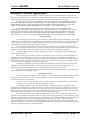
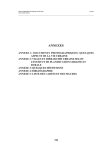
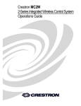
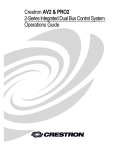
1
Crestron QM-RMC
Room Media Controller
Operations Guide
This document was prepared and written by the Technical Documentation department at:
Crestron Electronics, Inc.
15 Volvo Drive
Rockleigh, NJ 07647
1-888-CRESTRON
All brand names, product names and trademarks are the property of their respective owners.
©2003 Crestron Electronics, Inc.
Crestron QM-RMC
Room Media Controller
Contents
Room Media Controller: QM-RMC
1
Introduction ..........................................................................................................1
Features and Functions...........................................................................1
Specifications .........................................................................................3
Physical Description...............................................................................4
Memory..................................................................................................7
Industry Compliance ..............................................................................9
Setup.....................................................................................................................9
Hardware Hookup ..................................................................................9
Establishing Communication with the QM-RMC ................................10
Troubleshooting Communications .......................................................13
Compiling and Uploading a Program to the Control System ...............15
Uploading Web pages to the QM-RMC...............................................16
Updating the Operating System ...........................................................17
Advanced Console Commands ............................................................18
Programming the QM-RMC...............................................................................18
Programming with the Crestron AppBuilder .......................................19
Programming with SIMPL Windows...................................................19
Problem Solving .................................................................................................25
Troubleshooting ...................................................................................25
Further Inquiries...................................................................................28
Firmware Upgrades..............................................................................28
Future Updates .....................................................................................28
Software License Agreement..............................................................................29
Return and Warranty Policies.............................................................................31
Merchandise Returns / Repair Service .................................................31
CRESTRON Limited Warranty ...........................................................31
Operations Guide – DOC. 6161
Contents • i
Crestron QM-RMC
Room Media Controller
Room Media Controller:
QM-RMC
Introduction
Features and Functions
The QM-RMC is a low cost IP management tool to help facilities easily control
and monitor A/V devices. This powerful, compact control system enables serial,
IR, and Ethernet devices such as projectors, switchers, TVs, and other A/V
equipment to be controlled over IP networks. QM-RMC is an ideal solution for
colleges, universities, and other multi-room installations. It is a full-scale control
system with complete support of all Crestron e-Control® 2 and power
applications.
Functional Summary
Operations Guide – DOC. 6161
•
Powerful 2-Series processor, based on Motorola’s ColdFire®
technology, with non-volatile memory.
•
Native e-mail client
•
Supports DHCP, DNS and SSL (refer to the notes following this
summary).
•
Supports XPanel IE/EXE/PDA control (Crestron e-Control®2).
•
Programmable logic via SIMPL Windows, including SIMPL+®
•
Flash memory and DRAM.
•
Two bi-directional COM ports with built-in serial drivers for
controlling devices over RS-232.
•
One IR port - compatible with Crestron ST-SPL IR-Splitter, for IRControl of up to five different devices, programmable via the hundreds
of IR device drivers available in the Crestron databases.
•
Four digital input ports for direct connection of power sensors, pressure
sensors, door sensors, room occupancy sensor, etc.
•
A 10/100 Ethernet LAN port with built-in Web server and support for
DHCP; and support for all Crestron e-Control power applications and
Crestron RoomView™ A/V facility monitoring and management
software.
•
When used with Crestron RoomView™, provides remote power
control and management of A/V devices, including: monitoring lamp
life of projectors, device status to ensure proper equipment operations,
room occupancy, equipment use log, and device and room security.
Room Media Processor: QM-RMC • 1
Room Media Controller
Crestron QM-RMC
NOTE: DHCP (Dynamic Host Configuration Protocol) is a network protocol
that enables a DHCP server to automatically assign an IP address to an
individual computer's TCP/IP stack software. DHCP assigns a number
dynamically from a defined range of numbers (i.e., a scope) configured for a
given network.
NOTE: DNS stands for Domain Name Service (or System). Its primary use is
to translate, or resolve, the IP number for a computer (e.g., 129.79.5.208) from
an alphanumeric name.
NOTE: SSL, or Secure Socket Layer, is the most commonly used protocol for
Web security. In addition to providing security for HTTP (Web hypertext)
transactions, SSL works with other TCP/IP standards such as IMAP mail and
LDAP directory access. For a security standard such as SSL to work, the
browser and the Web server must both be configured to use it.
The QM-RMC is a stand-alone processor with all of the capabilities of a 2Series processor, without the Cresnet® port. The QM-RMC is programmed with
SIMPL Windows and has a built-in web server, native email client, supports
DHCP and DNS, as well as SSL (Secure Socket Layer - Industry standard
network security native to all Crestron 2-Series control systems). Versatile
enough to operate as a standalone control system, the QM-RMC is also ideally
suited for integration with an MP2E, MC2E or the CP2E low-cost room control
solutions.
The QM-RMC provides a 10/100 Ethernet port with support for DHCP and a
built-in Web server, so users can control serial devices from any computer on
the LAN, WAN, or even the Internet. Create customized Web pages using
Crestron VisionTools® Pro-e software, eliminating the need for third-party Web
page design software.
In fact, the new Crestron e-Control® 2 technology gives Web pages the same
look and feel as Crestron’s TPS ISYS® touchpanel pages, with almost zero
latency. This means you can add multi-mode buttons, gauges, sliders, subpages
and high-resolution graphics to your Web page projects, and the runtime
performance will be the same as with TPS touchpanels. Crestron e-Control 2
also generates standalone executables allowing users to launch from their
Windows® desktop, or Windows XP/Windows, CE StrongARM, XScale, Web
Tablet/Handheld PC, or Pocket PC 2002 PDA.
Some applications that QM-RMC can be used to monitor include: remote power
control/management of A/V devices, lamp life of projectors, device status to
ensure proper equipment operations, room occupancy, and room and/or device
security. It can also be used to remotely lock out projector/display controls from
unwanted users or to log equipment usage. Combined with the power of
Crestron RoomView™ software, hundreds of rooms with QM-RMCs can be
centrally monitored as to the status of all the above-mentioned functions by
multiple AV-personnel using PC/laptops connected to their LAN/WAN/Internet.
2 • Room Media Processor: QM-RMC
Operations Guide - DOC. 6161
Crestron QM-RMC
Room Media Controller
Specifications
Specifications for the QM-RMC are given in the following table.
QM-RMC Specifications
SPECIFICATION
DETAILS
®
CPU
32-Bit Motorola 5272 ColdFire Processor
Processor Speed
63 MIPS (Dhrystone 2.1 Benchmark)
Memory
36MB (4MB flash, 32MB SDRAM, 256KB NVRAM)
Ports/Connectors
1
2
LAN
One – RJ-45 10/100 BaseT Ethernet port
INFRARED – Serial
Input
One – 2-Position Mini connector IR port (Supports up to five
IR devices)
INPUT
COM (A & B)
One – 5-Position Mini connector (four inputs and GND)
Two – DB9 bidirectional serial ports (RS-232) baud rate up to
115,200 bps (Port B is used for initial communication and
setup).
12VDC
One – Male receptacle for external power pack (included)
Reset Buttons
HW-R
Initiates system hardware reset
SW-R
System restart with or without program
Power Requirements
6 W (0.5 Amp @ 12 VDC) power supply included
Initial Firmware Release
3.052
Environmental
Temperature
41° to 113°F (5° to 45°C)
Environmental Humidity
10% to 90% RH (non-condensing)
Dimensions & Weight
Height:
Width:
Depth:
Weight:
1.43 in (3.63 cm)
4.65 in (11.81 cm)
5.24 in (13.31 cm)
1.34 lb (0.61 kg)
1. For more information on system memory usage, refer to “Memory” on page 7.
2. For more information on controls, ports, and indicators, refer to “Physical Description” on page 4.
Operations Guide – DOC. 6161
Room Media Processor: QM-RMC • 3
Room Media Controller
Crestron QM-RMC
Physical Description
The QM-RMC is housed in a black enclosure with labels on the front and rear
panels. On the front of the unit there are six LEDs for indicating the unit’s
current status, two LEDs on the LAN connector, and two reset buttons. All
connections, except for the Ethernet and power connections, are made on the
back of the unit. There are four rubber feet on the base of the unit for stability
and to prevent slippage. Refer to the physical views shown below.
Front and Rear Views
Physical Dimensions
4.65 in
(11.81 cm)
1.43 in
(3.63 cm)
4 • Room Media Processor: QM-RMC
5.24 in
(13.31 cm)
Operations Guide - DOC. 6161
Crestron QM-RMC
Room Media Controller
Controls and Indicators
The QM-RMC front panel indicators and controls are described as follows.
12VDC
0.5A
LAN
COM A
IR
COM B
INPUT
HW-R
SW-R
PWR
ACT
QM-RMC
COM A
LED indicates COM A port activity.
COM B
LED indicates COM B port activity. Constant blinking indicates that the port is
used for remote console connection.
IR
LED indicates IR port activity.
INPUT
LED indicates input activity.
HW-R
Pressing this button initiates system hardware reset. (Same effect as
disconnecting and reconnecting power.)
SW-R
Pressing this button in combination with the HW-R button performs a system
restart without loading the program (refer to “Troubleshooting
Communications” on page 13). Press HW-R momentarily while pressing and
holding SW-R to reboot.
Pressing SW-R alone while the system is running restarts the program, and puts
the unit at a default IP address. COM B port becomes a remote console
connection.
PWR (Power)
This green LED illuminates when the unit is connected to and receives 12 VDC
power from an external power pack.
ACT (LAN)
This LED illuminates when the QM-RMC communicates with any device on the
network.
Operations Guide – DOC. 6161
Room Media Processor: QM-RMC • 5
Room Media Controller
Crestron QM-RMC
Front Panel Ports
The QM-RMC front panel ports are illustrated and described as follows.
LAN
LAN
Green
Yellow
8
1
An 8-position RJ-45 port (labeled LAN) is used for connection to the Ethernet,
providing local area network or Web access (cable is not supplied). The port
also contains two light-emitting diodes (LEDs). The green LED on the right
side of the port is a link status LED and illuminates when the card is connected
to a working network. The yellow LED on the left side flashes to indicate
Ethernet activity. Refer to the following table for the Ethernet connector
signals and use an appropriate cable.
LAN 8-Position RJ-45 Connector Specifications
PIN
SIGNALS
1
TD +
2
TD -
3
RD +
4
Connected to pin 5
5
Connected to pin 4
6
RD -
7
Connected to pin 8
8
Connected to pin 7
PIN 8
PIN 1
NOTE: To determine the location of pin 1, hold the cable so that the end of
the eight pin modular jack is facing away from you, with the clip up and
copper side down. Pin 1 is on the far right.
Default Ethernet Ports
80 = Web
41794 = Crestron Com
41795 = Viewport/Debug
12VDC
0.5A
12VDC, 0.5A (Power Supply)
This male connector can be used to supply 12 VDC power to the QM-RMC
from an external power pack (included).
CAUTION: Use only Crestron power supplies for Crestron equipment.
Failure to do so could cause equipment damage or void the Crestron warranty.
6 • Room Media Processor: QM-RMC
Operations Guide - DOC. 6161
Crestron QM-RMC
Room Media Controller
Rear Panel Ports
The QM-RMC rear panel ports are illustrated and described as follows.
INPUT
INPUT
1234G
This connector provides four software programmable digital inputs. Inputs are
Schmidt trigger type (nominal 2.5 V threshold) with 24 V input tolerance. For
detailed information, refer to “Slot 2: C21-DI04” on page 21.
Digital inputs are rated 0 – 24 VDC, 20K ohms input impedance.
IR
IR
S G
COM A
A 2-position mini-connector is a mini-implementation of a single PRO2 IR
port. The output is labeled S (signal) and G (ground). Infrared output is rated
up to 1.2 MHz, at data rates up to 9600 baud. Serial protocols include oneway RS-232. For detailed information, refer to “Slot 1: C2I-IR1” on page 20.
COM B
COM (A & B)
These two DB9 (male) software programmable, bi-directional serial ports are
available for RS-232 communication, with hardware and software
handshaking and modem control. Speeds are rated up to 115,200 bps.
COM B is used as the console port.
Standard COM DB9 Pinout
PIN
DIRECTION
DESCRIPTION
1
TO QM-RMC
(DCD) Data Carrier Detect
2
To QM-RMC
(RXD) Receive Data
3
From QM-RMC
(TXD) Transmit Data
4
From QM-RMC
(DTR) Data Terminal Ready
5
Common
(SG) Signal Ground
7
From QM-RMC
(RTS) Request To Send
8
To QM-RMC
(CTS) Clear To Send
9
To QM-RMC
(RI) Ring Indicator
Memory
The QM-RMC has 36MB of built-in memory (non-volatile and volatile). The
total of 36MB is specified as follows: 4MB flash (non-volatile), 32MB SDRAM
(volatile), and 256KB NVRAM (battery backed up). Flash memory contains the
file system inside the 2-Series control engine. Non-volatile memory contains
information that is retained after the loss of electrical power. Volatile memory is
lost after a power failure. Refer to the following lists for a breakdown of
memory usage for program-related information stored in the unit.
Operations Guide – DOC. 6161
Room Media Processor: QM-RMC • 7
Room Media Controller
Crestron QM-RMC
Flash
1.
SIMPL Program (.smw)
2.
SIMPL+ Modules (.usp/.ush)
3.
Operating System (.cuz file)
The 4MB flash memory consists of approximately 1.5MB used for firmware,
and approximately 2.5MB available for SIMPL, SIMPL+, and Web pages. The
files that reside in flash conform to a flat directory structure. The following table
presents the structure of the overall file system.
Flash File Structure
TOP LEVEL
SECONDARY LEVEL
\
DESCRIPTION
Root of the file system
DISPLAY
Legacy directory used in
Crestron Isys® panels to
hold display lists
SYS
Contains various system
configuration files
SETUP
Legacy directory used in
Crestron Isys® panels to
hold display lists
HTML
Web pages
SIMPL
Control system program
files
SPLUS
SIMPL+ module files
USER
Used for user-defined files
MAILBOX
Directory contains the user
mailbox file
CFØ
The mounting point for the
compact flash files.
\CFØ\DISPLAY
Directory used to hold
display files
\nvram
The mounting point for
NVRAM disk files
Although the file system is case insensitive, the case is preserved to maintain file
checksums.
Non-volatile
1.
SIMPL+ Variables (Default if no options are specified, or using
"nonvolatile" qualifier or #DEFAULT_NONVOLATILE)
2.
Signals explicitly written to NVRAM* (by symbols such as Analog
RAM, Analog RAM from database, Serial RAM, Serial RAM from
database, Analog Non-volatile Ramp, Digital RAM, etc.)
*Commonly used for presets (volume/lighting/dial #s).
3.
8 • Room Media Processor: QM-RMC
Portions of the NVRAM may be set aside for implementing an
“NVRAM Disk”. This can be used to provide file system access from
SIMPL+.
Operations Guide - DOC. 6161
Crestron QM-RMC
Room Media Controller
NOTE: If you extract NVRAM values to a file (Viewport, File transfer | Save
NVRAM to File), to simplify restoring them in the event of file corruption or to
distribute to identical control systems, remember that NVRAM values are position
sensitive in the program. When saving the NVRAM is crucial to your application,
it is recommended to place all symbols and/or modules that use NVRAM at the
beginning of your program. When NVRAM (.nvr file) is re-installed, all the values
should line up with the program. If the program is modified, and new logic that
uses NVRAM is placed before any older symbols using NVRAM, the previously
stored values will not line up and your presets will have to be re-entered.
NOTE: The new NVRAMDISK command (available in CUZ files later than
3.030), will fail unless it can determine the amount of NVRAM used by the
program, to ensure that the NVRAM is not overwritten. Programs compiled in
SIMPL Windows version 2.04.11 or later can provide this information. In the
event of a failure of the NVRAMDISK command, ensure that your program has
been recompiled in an appropriate version of SIMPL Windows and reloaded.
Volatile (DRAM)
1.
Digital, analog and serial signal values
2.
SIMPL+ Variables (Default if no options are specified, or if "volatile"
qualifier is used, or #DEFAULT_VOLATILE is used)
DRAM is used by the operating system for dynamic storage of variables, signals
and other constructs used at runtime. The actual amount of DRAM used at any
given time depends on the particular program that is running, i.e., usage is
variable, or dynamic, during normal operation.
Industry Compliance
As of the date of manufacture, the QM-RMC has been tested and found to
comply with specifications for CE marking and standards per EMC and
Radiocommunications Compliance Labelling (N11785).
NOTE: This device complies with part 15 of the FCC rules. Operation is
subject to the following two conditions: (1) this device may not cause harmful
interference, and (2) this device must accept any interference received, including
interference that may cause undesired operation.
Setup
Hardware Hookup
Refer to the following hookup diagram and, aside from attaching power last,
complete the connections in any order.
NOTE: To prevent overheating, do not operate this product in an area that
exceeds the environmental temperature range listed in the specifications table.
Consideration must be given if installed in a closed or multi-unit rack assembly
since the operating ambient temperature of the rack environment may be greater
than the room ambient. Contact with thermal insulating materials should be
avoided on all sides of the unit.
Operations Guide – DOC. 6161
Room Media Processor: QM-RMC • 9
Room Media Controller
Crestron QM-RMC
NOTE: The maximum continuous current from equipment under any external
load conditions shall not exceed a current limit that is suitable for the minimum
wire gauge used in interconnecting cables. The ratings on the connecting unit's
supply input should be considered to prevent overloading the wiring.
Front Connections
12VDC
0.5A
LAN
COM A
IR
COM B
INPUT
HW-R
SW-R
PWR
ACT
QM-RMC
LAN Connection
Power Connection
Rear Connections
INPUT
1 2 3 4 G
IR
S G
COM B
COM A
CRESTRON ELECTRONICS INC. ROCKLEIGH, N.J. 07647
Four Analog/Digital
Inputs
IR Output
Connection
Serial Port
Connections
NOTE: COM B is shared for device control and serial console connection.
Establishing Communication with the QM-RMC
Before uploading a program to the QM-RMC or performing diagnostic
functions, you must connect the QM-RMC system to the PC. The connection
can be either serial or TCP/IP.
NOTE: For laptops and other PCs without a built-in RS-232 port, Crestron
recommends the use of PCMCIA cards, rather than USB-to-serial adapters. If a
USB-to-serial adapter must be used, Crestron has tested the following devices
with good results:
Belkin (large model) F5U103
I/O Gear GUC232A
Keyspan USA-19QW
Other models, even from the same manufacturer, may not yield the same results.
Serial Connection
Connect the COM B port on the QM-RMC control system to one of the COM
ports (usually COM 1) on the PC. Use a null-modem RS-232 cable with DB9
female connectors on both ends. Most commercially available cables are
10 • Room Media Processor: QM-RMC
Operations Guide - DOC. 6161
Crestron QM-RMC
Room Media Controller
acceptable; they should have at least five pins for transmit, receive, ground, and
hardware handshaking (pins 2, 3, 5, 7 and 8).
Serial console connection may be established only if SW-R button is pressed
and held during power up, or if pressed and held at the same time HW-R is
momentarily pressed.
NOTE: The Viewport utility performs multiple system tasks, primarily via an
RS-232 or TCP/IP connection between the control system and a PC. It is used to
observe system processes, upload new operating systems and firmware, change
system and network parameters, and communicate with network device consoles
and touchpanels, among many other tasks. Viewport can also function as a
terminal emulator for generic file transfer. All of these functions are accessed
through the commands and options in the Viewport menus. Viewport is
available through the SIMPL Windows and Crestron VisionTools® (VT Pro-e)
software.
Open the Crestron Viewport and click Setup | Communication Settings to
display the “Port Settings” window. Then click RS-232 as the connection type.
NOTE: Changes in communication settings are not saved after the QM-RMC is
rebooted. It reverts to default settings.
The PC communication settings specified here should match the protocol that
the QM-RMC expects. The settings are as follows:
Operations Guide – DOC. 6161
•
Port = COM 1 through COM 8. Select the correct COM port on the PC.
•
Baud rate = 115200 (You can set the PC and the control system to a
different baud rate, by using the Functions | Set Baud Rate command.
•
Parity = None.
•
Number of data bits = 8.
•
Number of stop bits = 1.
•
Hardware handshaking (RTS/CTS) enabled.
•
Software handshaking (XON/XOFF) not enabled.
Room Media Processor: QM-RMC • 11
Room Media Controller
Crestron QM-RMC
“Port Settings” Window:
Default PC Settings for RS-232 Communication with the QM-RMC
To verify communication, click Diagnostics | Establish Communications
(Find Rack). This should display a window that gives the COM port and baud
rate.
TCP/IP Connection
Before you can communicate with the QM-RMC over TCP/IP, you must use the
RS-232 connection just described to configure the unit’s TCP/IP settings. Obtain
the static address from the network administrator.
1. Open Viewport and click Functions | Set Control System IP
Information.
2. Enter the IP address, IP mask and default router in the text fields. All of
these terms are explained in detail in the Crestron e-Control Reference
Guide, Doc. 6052. The latest version is available as a PDF on the
Crestron website (www.crestron.com).
3. Click OK to set the new IP information.
Once you have assigned the IP settings, you can continue to communicate with
the QM-RMC using the RS-232 connection, or you can establish a TCP/IP
connection.
For TCP/IP, use CAT5 straight through cables with 8-pin RJ-45 connectors to
connect the LAN port on the QM-RMC and the LAN port on the PC to the
Ethernet hub. Alternatively, you can use a CAT5 crossover cable to connect the
two LAN ports directly, without using a hub. The following figure illustrates
pinouts for straight through and crossover RJ-45 cables. Pins 4, 5, 7, and 8 are
not used.
12 • Room Media Processor: QM-RMC
Operations Guide - DOC. 6161
Crestron QM-RMC
Room Media Controller
RJ-45 Pinouts
Once the cable connections are made, open the Crestron Viewport and click
Setup | Communication Settings on the menu to display the “Port Settings”
window. Then click TCP/IP as the connection type. Enter the IP address of the
QM-RMC.
“Port Settings” Window
To verify communication, click Diagnostics | Establish Communications
(Find Rack). This should display a window that gives the IP address and port
number.
Troubleshooting Communications
Use the following checklist if communication cannot be established with the
QM-RMC.
Operations Guide – DOC. 6161
1.
Verify that you are using the correct cables. As described
previously, an RS-232 connection requires a null modem. TCP/IP
connection requires a CAT5 cable with 8-pin RJ-45 connectors.
2.
With a serial connection, verify that the correct COM port on the
PC has been selected. Some computers have more than one COM
port; some may be internal (e.g., for a modem). Consult the
Room Media Processor: QM-RMC • 13
Room Media Controller
Crestron QM-RMC
manufacturer’s documentation for further information about the
COM ports on your PC.
3.
Ensure that you have a serial connection to Port B, and reset the
control system as follows:
a.
Open Viewport and click Setup | Communications Settings
to display the “Port Settings” window. Choose RS-232 as the
connection type.
b.
Set the baud rate of the PC to 115200.
c.
Set the baud rate of the QM-RMC control system to 115200,
as follows:
-
Press and release the HW-R button on the unit’s front
panel.
-
Press and hold the SW-R button for approximately three
to five seconds. The Viewport console should display the
following message:
Viewport Message
QMRMC>
Control Console
Changing to default Comm Specs. 115200 N81 RTS/CTS
Switch to new settings….
Bypassing Program Load!!!
d.
14 • Room Media Processor: QM-RMC
Release the SW-R button.
If communication still cannot be established:
-
Remove power from the control system.
-
Press and hold the SW-R button on the front panel of the
QM-RMC.
-
Reapply power to the control system.
-
The Viewport console should display the message shown
above.
-
Release the SW-R button.
e.
Select Set Baud Rate on the Viewport Functions menu (or
press F8) and choose any baud rate from the drop-down list.
This will attempt to establish a connection at the indicated
baud rate. If the connection is successful, both the PC and the
control system will be set to the new baud rate. The QM-RMC
will return to its original communication settings when the
program reinitializes.
f.
Reinitialize the unit by recycling the power or pressing the
HW-R button while pressing and holding the SW-R button. If
the connection is established, the Viewport console should
display some text and the QMRMC> prompt.
g.
If communication still cannot be established, contact Crestron
customer service.
Operations Guide - DOC. 6161
Crestron QM-RMC
Room Media Controller
Compiling and Uploading a Program to the
Control System
After you have completed your SIMPL Windows program for the QM-RMC,
you must compile and upload the program to the control system.
To compile the program, simply click the Convert/Compile button
on the
SIMPL Windows toolbar, or select Project | Convert/Compile (you can also
press F12). A status bar indicates the progress of the compile operation. After
the operation is complete, a window displays information about the program
such as the number and type of signals, and memory usage.
The compiled program is stored as an SPZ file in the same directory as the
source file. There are a number of ways to upload an SPZ file to the control
system.
1. Immediately after compiling the program you have the option to transfer
the file to the control system.
2. Alternatively, click the Transfer button
on the SIMPL Windows
toolbar, or open Viewport and click File Transfer | Send Program.
3. Click Browse, locate the SPZ file and click Open. This displays the
program's header information and enables one or both of the What to
Send check boxes. If the program does not contain any SIMPL+
modules, only the SIMPL Program check box is enabled. If it does
contain SIMPL+ modules, then the SIMPL+ program(s) check box is
also enabled. Select one or both check boxes and then click Send
Program to begin the transfer.
NOTE: Unlike X-Generation processors, the 2-Series processor does not
require a permanent memory image. Also, the 2-Series adds the ability to
automatically retrieve the current program from the control system. Simply
verify that the Retrieve Current Program Before Overwriting check box is
selected.
You can also click Report Program Information or F7 from Diagnostics in
Viewport to display the header information of the currently loaded program.
Program information is also displayed in the Viewport console whenever power
is removed and re-applied to the QM-RMC.
Operations Guide – DOC. 6161
Room Media Processor: QM-RMC • 15
Room Media Controller
Crestron QM-RMC
“Send Program” Window
Uploading Web pages to the QM-RMC
The QM-RMC provides a built-in Web server for e-Control applications. The
QM-RMC allots 2.5 MB of memory for “user files” such as Web pages,
mailbox, and the compiled SPZ program file.
VisionTools Pro-e
In most cases, you create a VisionTools Pro-e browser project to generate the
Web pages for uploading to the QM-RMC.
For e-Control projects:
When an e-Control browser project is created, VT Pro-e automatically creates a
folder with the name of the project and a .web extension. This web project folder
itself contains a Java subfolder, in addition to all the HTML files that are sent to
the QM-RMC. In VT Pro-e, the target type is BROWSER.
For e-Control 2 projects:
When an e-Control 2 project is created, VT Pro-e automatically creates a folder
with the name of the project and a .xweb extension. The web project folder
contains all the necessary e-Control 2 files. In VT Pro-e, the target type is
XPANEL.
In designing and creating a browser project, keep in mind that you must assign
an IP ID to all the project pages and specify the IP address of the QM-RMC.
(For further information on this procedure, refer to the VT Pro-e online help
file.)
Viewport
To transfer the Web pages to the QM-RMC, use the File Transfer | Send Web
Pages command.
The options are to send an entire project, only files that have changed, or a
single HTML file. With the “Transfer Entire Project” option, click OK when
16 • Room Media Processor: QM-RMC
Operations Guide - DOC. 6161
Crestron QM-RMC
Room Media Controller
reminded to select a default page, and then browse to the appropriate VT Pro-e
.web project folder. Select the file that was designated as the “first” page of the
project. This will be the default Web page that is displayed whenever the IP
address of the control system is accessed by a Web browser. Click Open, and
then OK to begin the transfer.
If any files in the VT Pro-e project change, the changed files can be transferred
to the QM-RMC without resending the entire project by choosing the “Only
Transfer Files that have Changed” option. Here again, browse to the .web
project folder and select the default page. Click Open, and then OK to transfer
the changed files.
Finally, selecting “Transfer Single File” can send a single HTML file. Browse to
the file and click Open. Then specify the file’s relative path (from the root
directory) and click OK.
NOTE: For e-Control2, you can choose the default “Main.HTML” name or you
can change the name.
SIMPL Windows
For each IP ID in the VT Pro-e browser project, there must be one
corresponding e-Control PC Interface symbol defined in the SIMPL Windows
program. The PC Interface symbol is one of the Ethernet Modules that can be
dropped into the C2ENET-1 card slot.
As with all Ethernet devices, the PC Interface must receive an entry in the IP
Table of the QM-RMC. Here the IP ID must match the IP ID that was assigned
in VT Pro-e, while the IP address must be set to a loopback: 127.0.0.1, when
hosting internal.
Updating the Operating System
As with all 2-Series control systems, operating system files for the QM-RMC
have a .cuz extension. You can obtain .cuz updates (when available) from the
Downloads | Software Updates section of the Crestron website. To download an
update, click the .cuz file, choose the Save to Disk option, and then specify the
directory where the update is stored.
NOTE: In some cases Microsoft's Internet Explorer may append a .zip extension
to a downloaded .cuz file. For example, a file called "C2-1008.cuz" may appear
as "C2-1008.cuz.zip." If this happens, rename the file, removing the .zip
extension.
NOTE: Crestron software and any files on the website are for Authorized
Crestron dealers and Crestron Authorized Independent Programmers (CAIP)
only. New users may be required to register to obtain access to certain areas of
the site (including the FTP site).
To upload the new .cuz to the control system:
Operations Guide – DOC. 6161
1.
Open Viewport and select File | Update Control System.
2.
Browse to the .cuz file and click Open to start the transfer.
3.
After the transfer is complete, the QM-RMC automatically reboots. To
confirm the transfer, click Diagnostics | Check Operating System
Version. The Viewport console should display the new .cuz version
number.
Room Media Processor: QM-RMC • 17
Room Media Controller
Crestron QM-RMC
Advanced Console Commands
The SIMPL Windows online help file provides a full listing of console
commands that are valid for 2-Series control systems. You can access the QMRMC console in a variety of ways: via a serial connection (RS-232) with a PC
connected to port B, over Ethernet via the LAN port, or through Telnet, among
many other methods. It is also possible to issue console commands through
logic, by adding a Console symbol to the SIMPL Windows program.
The Console symbol is only visible in the Symbol Library when “Special” is
selected as the Symbol Set. Click Edit | Preferences. In the Symbol Set area of
the General tab, select Special as shown in the following graphic.
"SIMPL Windows Preferences" Window
Console commands are provided for advanced programmers. However, most
functions and commands can be selected from the various Viewport menus.
NOTE: For more information on console commands, refer to the 2-Series
Console Command Reference Guide (Doc. 6002). The latest version can be
obtained from the Downloads | Product Manuals section of the Crestron website
(www.crestron.com).
Programming the QM-RMC
Have a comment about Crestron
software?
Direct software related
suggestions and/or complaints to
Crestron via e-mail
([email protected]). Do not
forward and queries to this
address. Instead refer to “Further
Inquiries” on page 29 for
assistance.
You can create a program that allows you to control the QM-RMC control
system using the Crestron programming tools Crestron Application Builder™
(AppBuilder) and SIMPL Windows. These tools are intended for users with
different levels of programming knowledge. The flexibility of each tool is
proportional to the degree of programming expertise (i.e., the more flexible, the
more a programmer needs to know and account for). Of course, one can initiate
programming using the easiest method (Crestron AppBuilder) and use advanced
techniques that are available from SIMPL Windows to customize the job.
18 • Room Media Processor: QM-RMC
Operations Guide - DOC. 6161
Crestron QM-RMC
Room Media Controller
Following are the minimum software requirements for the PC:
•
SIMPL Windows version 2.04.11, with Library Update 234 or later.
(Also requires SIMPL+ Cross Compiler version 1.1). Crestron
Database version 15.9.9 or later for use with SIMPL Windows.
•
(Optional) VisionTools Pro-e software version 3.1.1.7 for designing
touchpanel pages.
•
(Optional) Crestron Application Builder version 1.2.3 software for
automatic residential and commercial programming of the QM-RMC as
a control system. As of press time, this version of Crestron Application
Builder had not been released. Please check the Crestron FTP site.
•
(Optional) DEAL for Windows IR learning software version 3.01
•
(Optional) Crestron RoomView™ version 2.0.0.3
Programming with the Crestron AppBuilder
Crestron AppBuilder is easier
to use for the beginning
programmer, and much faster
for all programmers. However
it does not allow the degree of
flexibility and control that
SIMPL Window does.
NOTE: The QM-RMC can be optionally programmed with Crestron
Application Builder version 1.2 software for automatic residential and
commercial programming of the QM-RMC as a control system. As of press
time, this version of Crestron Application Builder had not been released. Please
check the Crestron FTP site.
The Crestron AppBuilder interface guides you through a few basic steps for
designating rooms and specifying the control system, touchpanels, devices, and
functionality. The Crestron AppBuilder then programs the system, including all
touchpanel projects and control system logic.
The Crestron AppBuilder is fully integrated with the Crestron suite of software
development tools, including SIMPL Windows, VT Pro-e, Crestron Database,
User IR Database, and User Modules Directory. The Crestron AppBuilder
accesses these tools behind the scenes, enabling you to easily create robust
systems.
Programming with SIMPL Windows
NOTE: The following are acceptable file extensions for programs that include
a QM-RMC, developed for specific control system types:
projectname.smw (source file)
projectname.spz (compiled file for 2-Series)
projectname.usp (source code module for SIMPL+)
SIMPL Windows is the Crestron graphical, Windows-based development tool
for programming control systems. The SIMPL Windows interface provides two
workspaces: the Configuration Manager, for configuring the control system,
touchpanels, and controlled network devices; and Program Manager, for
designing the logic and functionality of the control system.
In addition, you can use the powerful Crestron Viewport utility to accomplish
multiple system tasks, such as uploading the program to the control system and
performing diagnostic functions. Together with the Crestron Database, these
tools provide you with the essential components you need to program the QMRMC. Crestron software is available from the Crestron website
(www.crestron.com)—registration is required for downloading.
Operations Guide – DOC. 6161
Room Media Processor: QM-RMC • 19
Room Media Controller
Crestron QM-RMC
NOTE: Crestron software and any files on the website are for Authorized
Crestron dealers and Crestron Authorized Independent Programmers (CAIP)
only. New users may be required to register to obtain access to certain areas of
the site (including the FTP site).
NOTE: The information in this section assumes that the reader has knowledge
of SIMPL Windows. If not, refer to the extensive help information provided
with the software.
QM-RMC Device Library Symbols
In Configuration Manager, drag the QM-RMC from the Control Systems folder
of the Device Library to System Views.
System View of QM-RMC
Slot 1: C2I-IR1 Port A
Port A is the only port in Slot 1.
The C2I-IR1 provides one IR output port (A) for controlling devices via IR or
one-way RS-232. (Depending on the control format, additional equipment such
as IR emitters, splitters, receivers, and remote control transmitters may be
required).
To add an IR device, drag the device from the Crestron, Project, or User IR
Database to the C2I-IR1 port. The Crestron database contains hundreds of IR
driver files, covering most IR devices on the market today. The IR port requires
one IRP2 (infrared emitter probe) installed on each IR device. One end of the
emitter is installed on or near the IR sensor window of the controlled device
while the other end plugs into the C2I-IR1 port.
No more than four IR emitters should be connected to the IR port (the maximum
is five emitters when using the ST-SPL resistor/divider). In addition, if more
than two emitters are connected to the IR port then a 100 ohm resistor should be
placed between signal and ground for each emitter. Thus four emitters would
require four resistors.
Alternatively, the ST-MB (master blaster) IR sprayer can "spray" IR signals 90
degrees. It eliminates the need for IR probes and resistors, and can be positioned
20 • Room Media Processor: QM-RMC
Operations Guide - DOC. 6161
Crestron QM-RMC
Room Media Controller
to reach all devices. It is designed to handle multiple IR codes so that only one
sprayer is needed for many devices.
NOTE: The C2I-IR1 port does not support simultaneous IR and RS-232
control. That is, an IR driver cannot be stacked on the port together with a oneway serial driver. The control format must be of one type. Use only one 1-way
Serial Driver or up to five IR drivers.
In addition, the IR port does not have negative voltage and thus may not provide
the full voltage range required by some RS-232 devices (although nearly all RS232 devices will operate properly). In these cases the DB9 serial COM ports can
be used instead.
Slot 2: C2I-DI04
Slot 2 provides four digital input ports: <o1> through <o4>
Signals
•
Digitals: <o1> through <o4>
Description
The C2I-DIO4 provides four digital inputs for connection of external sensors or
other contact closure devices. The <o> outputs are a logical high until it detects
the presence of a low on the corresponding input.
The built-in port supports dry contact closure to ground.
Slot 3: C2I-COM2-232 - Port A and Port B
The C2I-COM2-232 provides two COM ports (A and B) for controlling serial
devices over RS-232.
NOTE: Does not support RS-422 or RS-485.
Each COM port has a built-in two-way serial driver.
To program a serial driver or serial device expand the C2I-COM-2 in Program
View and drag the item to Detail View.
Operations Guide – DOC. 6161
Room Media Processor: QM-RMC • 21
Room Media Controller
Crestron QM-RMC
Signals
•
Serial input for one-way and two-way serial drivers: <tx$> (transmit)
•
Serial output for two-way serial drivers: <rx$> (receive)
•
Digital inputs for two-way serial drivers: <rts> (request to send), <dtr>
(data terminal ready), <in1> through <in2000> and <break>
•
Digital output for two-way serial drivers: <cts> (clear to send),
<RingIn> (ring indicator), <CarrierDetect>, <dsr> (data set ready).
•
Digital input: <enable>
•
Parameters: <str1>, <str2>, <delimiter>
The <tx$> (transmit) and <rx$> (receive) signals send and receive serial strings
using whichever communication format, or protocol, the serial device requires.
This protocol is usually described in the manufacturer's documentation and
includes the transmission speed (baud rate), error checking (parity), number of
data bits and stop bits, and any hardware or software handshaking that may be
required to control the flow of data.
Slot 4: C2ENET-1
The C2ENET-1 network interface card provides one LAN port with an RJ-45
connector for connecting the QM-RMC to the Ethernet network.
The card provides 252 IP IDs for Ethernet devices.
To facilitate network functions and diagnostics, SIMPL Windows provides one
device extender for the C2ENET-1 card: Device Status.
To add the device extender, right-click the C2ENET-1 card in Program View,
point to Insert Device Extender and click Device Status.
To program an Ethernet device or device extender, expand the C2ENET-1 card
in Program View and drag the item to Detail View.
22 • Room Media Processor: QM-RMC
Operations Guide - DOC. 6161
Crestron QM-RMC
Room Media Controller
Sub-Slot 4.1 (Device Extender): Device Status
Speed Key Name: devstat
Signal
•
Digital output: <offline>
Description
The Device Status symbol is a device extender for plug-in control cards,
including the C2ENET-1 card. It reports the connection status of the card.
The <offline> input goes high for as long as a card is unavailable for polling or
is physically disconnected from its Ethernet slot. The <offline> input goes low
when the card is online.
Slot 5: C21-C2N-RMC2E-FRONTPANEL
The C2I Front Panel is the non-programmable front panel of the QM-RMC and
other 2-Series control systems and does not provide an LCD display or push
buttons.
Converting Programs and Modules Created for other
Systems
A useful feature of SIMPL Windows is that you can convert a program created
for another type of control system, simply by changing the target to a QM-RMC.
To do this you first open the program, and then replace the existing control
system with the QM-RMC. That is, drag the QM-RMC from the Control
Systems folder onto the existing control system in System Views, and click Yes
when prompted to confirm the replacement.
If the program contains SIMPL+ or User modules, the conversion might
generate error messages. This is because modules and programs often contain
symbols with “ambiguous” signals. For example, the inputs of the Serial to
Analog symbol can be defined as either analog or serial. Although X-Generation
processors support ambiguous signals, the 2-Series processor requires all signal
types to be strictly defined.
If the program you want to convert contains SIMPL+ or User modules, Crestron
recommends that you first compile each module before converting the larger
program. In this way, the compiler can resolve any ambiguous signals in the
modules and minimize errors when the larger program is converted.
Converting SIMPL+ Modules for 2-Series
Operations Guide – DOC. 6161
1.
Open the SIMPL+ module you want to convert.
2.
Choose the 2-Series processor as the target by clicking the toolbar
button, as shown in the following illustration.
Room Media Processor: QM-RMC • 23
Room Media Controller
Crestron QM-RMC
SIMPL+ Toolbar
NOTE: Note that you can select both X and 2-Series as the targets, so that the
module works for both types of control systems. However, you are limited to
SIMPL+ keywords and functions that are supported on both systems. If you do
not choose a target, then the module may or may not work, depending on the
constructs that are used.
3.
Save and compile the module by clicking the Save and Compile
toolbar button; alternatively, click Save and Compile on the Build
menu (or press F12).
Converting User Modules
1.
Open the User module you want to convert.
2.
Click Project | Edit Program Header.
3.
Click 2-Series in the Target Control System Classes list box.
You can select other types of control systems as well, but then you are limited to
symbols that are supported by all of these platforms. The module may still work
on unselected control systems so long as unsupported symbols are not used.
Selecting a control system means that you are requiring the module to work
there.
“Module Header Information” Window
24 • Room Media Processor: QM-RMC
Operations Guide - DOC. 6161
Crestron QM-RMC
Room Media Controller
After you convert each module in a program, you can convert the program as
described previously: drag the QM-RMC onto the existing control system in
System Views and click Yes to confirm the replacement.
For further information about compile-time errors and detailed explanations
about working with modules, refer to the SIMPL Windows online help file.
Problem Solving
Troubleshooting
The following table provides corrective action for possible trouble situations. If
further assistance is required, please contact a Crestron customer service
representative.
QM-RMC Troubleshooting
TROUBLE
POSSIBLE
CAUSE(S)
CORRECTIVE ACTION
PWR LED
does not
illuminate.
Control system is not
receiving power.
Verify that the DC output plug is properly
attached to the control system and that
the adaptor is securely plugged into an
outlet.
Compilation
Error
RLCMCVT166
&
RLCMCVT177
Poor analog versus serial
signal definition in the
SIMPL Windows program.
Confirm properly defined signal
definition in the program.
System locks
up.
Various.
Press front panel SW-R and HW-R
buttons at the same time to bypass
program and communicate directly with
processor (refer to “Troubleshooting
Communications” on page 13).
System does
not function.
Various.
Refer to the “System Monitor” procedure
following this table.
Incorrect power supply.
Use a Crestron power supply.
IR or serial port not
connected properly.
Verify connections and tighten serial
cables.
Used wrong IR/Serial port.
Verify that proper IR or serial port is
defined.
Serial cable miswired.
Verify that serial cable is wired correctly
for RS-232.
A/V system
device does
not respond.
System Monitor
The System Monitor allows you to reload firmware into the QM-RMC in the
event that you cannot load the firmware in the normal mode.
Perform the following procedure to correct the “System does not function”
trouble situation (in reference to Corrective Action).
If the system does not function, perform the following procedure:
Operations Guide – DOC. 6161
1.
Connect DB9 null-modem RS-232 cable between the PC and QMRMC COM port B. Refer to “Hardware Hookup” on page 9.
2.
Open Viewport and select Setup | Communication Settings to open
the “Port settings” window.
Room Media Processor: QM-RMC • 25
Room Media Controller
Crestron QM-RMC
3.
In the window, select RS-232 (Connection Type), 57600 (Baud Rate),
N (Parity), 8 (Data Bits), 1 (Stop Bits), RTS/CTS On, XON/XOFF
Off, and click OK.
4.
Power down the QM-RMC.
5.
While powering up the QM-RMC, press and hold ATL and K on the
keyboard until the following text (or similar) appears in Viewport.
System Monitor [v1.001 (0001)]
12-19-01 16:25:23 32MB RAM, 4MB FLASH
CS>
NOTE: After this, you can increase the baud rate to 115200 (for faster
communication) by pressing F8 on the keyboard and then selecting 115200 from
the “Set Baud Rate” window.
6.
At the Viewport prompt, type: erase and press Enter. The following
text appears in Viewport.
CS>erase
->25%->50%->75%->100%
Done
CS>
7.
Press ALT and O (not zero) on the keyboard. The “Open” window
appears. Click: File Transfer | Update Control System.
8.
Find and select the correct firmware file (.CUZ) and click Open.
9.
Once “Completed Successfully” appears in Viewport, type quit at the
Viewport prompt and press Enter.
Battery Replacement
A Lithium battery is used to power the system clock within the QM-RMC.
Under normal conditions, it lasts for approximately 10 years. In the event that
the clock fails, only an authorized technician should replace it. Refer to the
following caution statement.
CAUTION: Danger of explosion if battery is incorrectly replaced.
Replace only with the same or equivalent type recommended by the
manufacturer. Dispose of used batteries according to the manufacturer's
instructions.
Passthrough Mode
Passthrough mode enables Viewport access to any serially controlled device on
the network. That is, it allows direct communication between the PC and a
network device (effectively "passing through" the QM-RMC). While
Passthrough mode is running, the program currently in memory is suspended
and will not execute. When Passthrough mode is exited, the program resumes
operation.
Entering Passthrough mode for COM port B reinitializes it, which clears the
data for that port.
To establish communication, click Functions | Enter Passthrough Mode. Then
select the connection type that exists between the QM-RMC and the device. The
26 • Room Media Processor: QM-RMC
Operations Guide - DOC. 6161
Crestron QM-RMC
Room Media Controller
choices are Slot (for devices connected to the control system via one of the card
slots on the back panel), or Ethernet. If the connection is through a card slot then
select the slot number from the Slot drop-down list. For Ethernet, select the IP
ID.
NOTE: The IP ID and associated IP address of the Ethernet device must be
listed in the IP Table.
Specify the port (Port A or Port B) that the device is connected to, if applicable.
Next, specify the serial protocol that the device expects. The parameters include
the baud rate, parity, the number of data bits and stop bits, the protocol (RS232), and the settings for software or hardware handshaking. This information is
provided by the manufacturer’s documentation.
“Passthrough Mode” Window
The PC is now communicating directly with the device.
To exit Passthrough mode, simply click Functions | Exit Passthrough Mode. A
system reboot also exits the Passthrough mode.
Operations Guide – DOC. 6161
Room Media Processor: QM-RMC • 27
Room Media Controller
Crestron QM-RMC
Further Inquiries
If after reviewing this Operations Guide, you cannot locate specific information
or have questions, please take advantage of the Crestron award winning
customer service team by calling:
•
In the US and Canada, call the Crestron corporate headquarters at
1-888-CRESTRON [1-888-273-7876].
•
In Europe, call Crestron International at +32-15-50-99-50.
•
In Asia, call Crestron Asia at +852-2341-2016.
•
In Latin America, call Crestron Latin America at
+5255-5093-2160.
•
In Australia and New Zealand, call Crestron Pacific at
+613-9480-2999.
Firmware Upgrades
To take advantage of all the QM-RMC features, it is important that the unit
contains the latest firmware available. Therefore, please check the Crestron
website (http://www.crestron.com/downloads/software_updates.asp) for the
latest version of firmware. Not every product has a firmware upgrade, but as
Crestron improves functions, adds new features, and extends the capabilities of
its products, firmware upgrades are posted. If you have questions regarding
upgrade procedures, contact Crestron customer service.
Future Updates
As Crestron improves functions, adds new features, and extends the capabilities
of the QM-RMC, additional information may be made available as manual
updates. These updates are solely electronic and serve as intermediary
supplements prior to the release of a complete technical documentation revision.
Check the Crestron website (www.crestron.com) periodically for manual update
availability and its subjective value. Updates are available from the Downloads |
Product Manuals section and are identified as an “Addendum” in the Download
column.
28 • Room Media Processor: QM-RMC
Operations Guide - DOC. 6161
Crestron QM-RMC
Room Media Controller
Software License Agreement
This License Agreement (“Agreement”) is a legal contract between you (either an individual or a single business
entity) and Crestron Electronics, Inc. (“Crestron”) for software referenced in this guide, which includes computer software and,
as applicable, associated media, printed materials, and “online” or electronic documentation (the “Software”).
BY INSTALLING, COPYING, OR OTHERWISE USING THE SOFTWARE, YOU REPRESENT THAT YOU
ARE AN AUTHORIZED DEALER OF CRESTRON PRODUCTS OR A CRESTRON AUTHORIZED INDEPENDENT
PROGRAMMER AND YOU AGREE TO BE BOUND BY THE TERMS OF THIS AGREEMENT. IF YOU DO NOT
AGREE TO THE TERMS OF THIS AGREEMENT, DO NOT INSTALL OR USE THE SOFTWARE.
IF YOU HAVE PAID A FEE FOR THIS LICENSE AND DO NOT ACCEPT THE TERMS OF THIS
AGREEMENT, CRESTRON WILL REFUND THE FEE TO YOU PROVIDED YOU (1) CLICK THE DO NOT ACCEPT
BUTTON, (2) DO NOT INSTALL THE SOFTWARE AND (3) RETURN ALL SOFTWARE, MEDIA AND OTHER
DOCUMENTATION AND MATERIALS PROVIDED WITH THE SOFTWARE TO CRESTRON AT: CRESTRON
ELECTRONICS, INC., 15 VOLVO DRIVE, ROCKLEIGH, NEW JERSEY 07647, WITHIN 30 DAYS OF PAYMENT.
LICENSE TERMS
Crestron hereby grants You and You accept a nonexclusive, nontransferable license to use the Software (a) in machine
readable object code together with the related explanatory written materials provided by Creston (b) on a central processing unit
(“CPU”) owned or leased or otherwise controlled exclusively by You, and (c) only as authorized in this Agreement and the
related explanatory files and written materials provided by Crestron.
If this software requires payment for a license, you may make one backup copy of the Software, provided Your
backup copy is not installed or used on any CPU. You may not transfer the rights of this Agreement to a backup copy unless the
installed copy of the Software is destroyed or otherwise inoperable and You transfer all rights in the Software.
You may not transfer the license granted pursuant to this Agreement or assign this Agreement without the express
written consent of Crestron.
If this software requires payment for a license, the total number of CPU’s on which all versions of the Software are
installed may not exceed one per license fee (1) and no concurrent, server or network use of the Software (including any
permitted back-up copies) is permitted, including but not limited to using the Software (a) either directly or through commands,
data or instructions from or to another computer (b) for local, campus or wide area network, internet or web hosting services; or
(c) pursuant to any rental, sharing or “service bureau” arrangement.
The Software is designed as a software development and customization tool. As such Crestron cannot and does not
guarantee any results of use of the Software or that the Software will operate error free and You acknowledge that any
development that You perform using the Software or Host Application is done entirely at Your own risk.
The Software is licensed and not sold. Crestron retains ownership of the Software and all copies of the Software and
reserves all rights not expressly granted in writing.
OTHER LIMITATIONS
You must be an Authorized Dealer of Crestron products or a Crestron Authorized Independent Programmer to install
or use the Software. If Your status as a Crestron Authorized Dealer or Crestron Authorized Independent Programmer is
terminated, Your license is also terminated.
You may not rent, lease, lend, sublicense, distribute or otherwise transfer or assign any interest in or to the Software.
You may not reverse engineer, decompile, or disassemble the Software.
You agree that the Software will not be shipped, transferred or exported into any country or used in any manner
prohibited by the United States Export Administration Act or any other export laws, restrictions or regulations (“Export Laws”).
By downloading or installing the Software You (a) are certifying that You are not a national of Cuba, Iran, Iraq, Libya, North
Korea, Sudan, or Syria or any country to which the United States embargoes goods (b) are certifying that You are not otherwise
prohibited from receiving the Software and (c) You agree to comply with the Export Laws.
If any part of this Agreement is found void and unenforceable, it will not affect the validity of the balance of the
Agreement, which shall remain valid and enforceable according to its terms. This Agreement may only be modified by a writing
signed by an authorized officer of Crestron. Updates may be licensed to You by Crestron with additional or different terms. This
is the entire agreement between Crestron and You relating to the Software and it supersedes any prior representations,
discussions, undertakings, communications or advertising relating to the Software. The failure of either party to enforce any
right or take any action in the event of a breach hereunder shall constitute a waiver unless expressly acknowledged and set forth
in writing by the party alleged to have provided such waiver.
Operations Guide – DOC. 6161
Room Media Processor: QM-RMC • 29
Room Media Controller
Crestron QM-RMC
If You are a business or organization, You agree that upon request from Crestron or its authorized agent, You will
within thirty (30) days fully document and certify that use of any and all Software at the time of the request is in conformity with
Your valid licenses from Crestron of its authorized agent.
Without prejudice to any other rights, Crestron may terminate this Agreement immediately upon notice if you fail to
comply with the terms and conditions of this Agreement. In such event, you must destroy all copies of the Software and all of its
component parts.
PROPRIETARY RIGHTS
Copyright. All title and copyrights in and to the Software (including, without limitation, any images, photographs,
animations, video, audio, music, text, and “applets” incorporated into the Software), the accompanying media and printed
materials, and any copies of the Software are owned by Crestron or its suppliers. The Software is protected by copyright laws
and international treaty provisions. Therefore, you must treat the Software like any other copyrighted material, subject to the
provisions of this Agreement.
Submissions. Should you decide to transmit to the Crestron website by any means or by any media any materials or
other information (including, without limitation, ideas, concepts or techniques for new or improved services and products),
whether as information, feedback, data, questions, comments, suggestions or the like, you agree such submissions are
unrestricted and shall be deemed non-confidential and you automatically grant Crestron and its assigns a non-exclusive, royaltytree, worldwide, perpetual, irrevocable license, with the right to sublicense, to use, copy, transmit, distribute, create derivative
works of, display and perform the same.
Trademarks. CRESTRON and the Swirl Logo are registered trademarks of Crestron Electronics, Inc. You shall not
remove or conceal any trademark or proprietary notice of Crestron from the Software including any back-up copy.
GOVERNING LAW
This Agreement shall be governed by the laws of the State of New Jersey, without regard to conflicts of laws
principles. Any disputes between the parties to the Agreement shall be brought in the state courts in Bergen County, New Jersey
or the federal courts located in the District of New Jersey. The United Nations Convention on Contracts for the International
Sale of Goods, shall not apply to this Agreement.
CRESTRON LIMITED WARRANTY
CRESTRON warrants that: (a) the Software will perform substantially in accordance with the published
specifications for a period of ninety (90) days from the date of receipt, and (b) that any hardware accompanying the Software
will be subject to its own limited warranty as stated in its accompanying written material. Crestron shall, at its option, repair or
replace or refund the license fee for any Software found defective by Crestron if notified by you within the warranty period. The
foregoing remedy shall be your exclusive remedy for any claim or loss arising from the Software.
CRESTRON shall not be liable to honor warranty terms if the product has been used in any application other than that
for which it was intended, or if it as been subjected to misuse, accidental damage, modification, or improper installation
procedures. Furthermore, this warranty does not cover any product that has had the serial number or license code altered,
defaced, improperly obtained, or removed.
Notwithstanding any agreement to maintain or correct errors or defects Crestron, shall have no obligation to service or
correct any error or defect that is not reproducible by Crestron or is deemed in Crestron’s reasonable discretion to have resulted
from (1) accident; unusual stress; neglect; misuse; failure of electric power, operation of the Software with other media not
meeting or not maintained in accordance with the manufacturer’s specifications; or causes other than ordinary use; (2) improper
installation by anyone other than Crestron or its authorized agents of the Software that deviates from any operating procedures
established by Crestron in the material and files provided to You by Crestron or its authorized agent; (3) use of the Software on
unauthorized hardware; or (4) modification of, alteration of, or additions to the Software undertaken by persons other than
Crestron or Crestron’s authorized agents.
ANY LIABILITY OF CRESTRON FOR A DEFECTIVE COPY OF THE SOFTWARE WILL BE LIMITED
EXCLUSIVELY TO REPAIR OR REPLACEMENT OF YOUR COPY OF THE SOFTWARE WITH ANOTHER COPY OR
REFUND OF THE INITIAL LICENSE FEE CRESTRON RECEIVED FROM YOU FOR THE DEFECTIVE COPY OF THE
PRODUCT. THIS WARRANTY SHALL BE THE SOLE AND EXCLUSIVE REMEDY TO YOU. IN NO EVENT SHALL
CRESTRON BE LIABLE FOR INCIDENTAL, CONSEQUENTIAL, SPECIAL OR PUNITIVE DAMAGES OF ANY KIND
(PROPERTY OR ECONOMIC DAMAGES INCLUSIVE), EVEN IF A CRESTRON REPRESENTATIVE HAS BEEN
ADVISED OF THE POSSIBILITY OF SUCH DAMAGES OR OF ANY CLAIM BY ANY THIRD PARTY. CRESTRON
MAKES NO WARRANTIES, EXPRESS OR IMPLIED, AS TO TITLE OR INFRINGEMENT OF THIRD-PARTY RIGHTS,
MERCHANTABILITY OR FITNESS FOR ANY PARTICULAR PURPOSE, OR ANY OTHER WARRANTIES, NOR
AUTHORIZES ANY OTHER PARTY TO OFFER ANY WARRANTIES, INCLUDING WARRANTIES OF
MERCHANTABILITY FOR THIS PRODUCT. THIS WARRANTY STATEMENT SUPERSEDES ALL PREVIOUS
WARRANTIES.
30 • Room Media Processor: QM-RMC
Operations Guide - DOC. 6161
Crestron QM-RMC
Room Media Controller
Return and Warranty Policies
Merchandise Returns / Repair Service
1.
No merchandise may be returned for credit, exchange, or service without prior
authorization from CRESTRON. To obtain warranty service for CRESTRON
products, contact the factory and request an RMA (Return Merchandise
Authorization) number. Enclose a note specifying the nature of the problem, name
and phone number of contact person, RMA number, and return address.
2.
Products may be returned for credit, exchange, or service with a CRESTRON Return
Merchandise Authorization (RMA) number. Authorized returns must be shipped
freight prepaid to CRESTRON, Cresskill, N.J., or its authorized subsidiaries, with
RMA number clearly marked on the outside of all cartons. Shipments arriving freight
collect or without an RMA number shall be subject to refusal. CRESTRON reserves
the right in its sole and absolute discretion to charge a 15% restocking fee, plus
shipping costs, on any products returned with an RMA.
3.
Return freight charges following repair of items under warranty shall be paid by
CRESTRON, shipping by standard ground carrier. In the event repairs are found to
be non-warranty, return freight costs shall be paid by the purchaser.
CRESTRON Limited Warranty
CRESTRON ELECTRONICS, Inc. warrants its products to be free from manufacturing defects in
materials and workmanship under normal use for a period of three (3) years from the date of
purchase from CRESTRON, with the following exceptions: disk drives and any other moving or
rotating mechanical parts, pan/tilt heads and power supplies are covered for a period of one (1)
year; touchscreen display and overlay components are covered for 90 days; batteries and
incandescent lamps are not covered.
This warranty extends to products purchased directly from CRESTRON or an authorized
CRESTRON dealer. Purchasers should inquire of the dealer regarding the nature and extent of the
dealer's warranty, if any.
CRESTRON shall not be liable to honor the terms of this warranty if the product has been used in
any application other than that for which it was intended, or if it has been subjected to misuse,
accidental damage, modification, or improper installation procedures. Furthermore, this warranty
does not cover any product that has had the serial number altered, defaced, or removed.
This warranty shall be the sole and exclusive remedy to the original purchaser. In no event shall
CRESTRON be liable for incidental or consequential damages of any kind (property or economic
damages inclusive) arising from the sale or use of this equipment. CRESTRON is not liable for
any claim made by a third party or made by the purchaser for a third party.
CRESTRON shall, at its option, repair or replace any product found defective, without charge for
parts or labor. Repaired or replaced equipment and parts supplied under this warranty shall be
covered only by the unexpired portion of the warranty.
Except as expressly set forth in this warranty, CRESTRON makes no other warranties, expressed
or implied, nor authorizes any other party to offer any warranty, including any implied warranties
of merchantability or fitness for a particular purpose. Any implied warranties that may be imposed
by law are limited to the terms of this limited warranty. This warranty statement supercedes all
previous warranties.
Trademark Information
All brand names, product names, and trademarks are the sole property of their respective owners. Windows is a registered
trademark of Microsoft Corporation. Windows95/98/Me/XP and WindowsNT/2000 are trademarks of Microsoft
Corporation.
Operations Guide – DOC. 6161
Room Media Processor: QM-RMC • 31
Crestron Electronics, Inc.
15 Volvo Drive Rockleigh, NJ 07647
Tel: 888.CRESTRON
Fax: 201.767.7576
www.crestron.com
Operations Guide – DOC. 6161
07.03
Specifications subject to
change without notice.