1
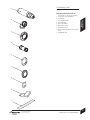
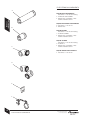
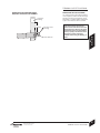
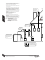
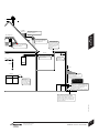
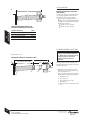
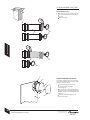
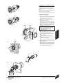
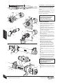
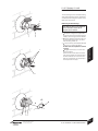
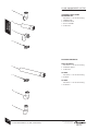
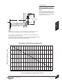
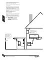
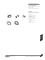
INSTRUCTION MANUAL
FLUE KIT INSTALLATION
7 716 191 155
7 716 191 086
ROOM SEALED TELESCOPIC FLUE
PLUME MANAGEMENT SYSTEM
60/100 HORIZONTAL FLUE
FOR USE WITH WORCESTER APPLIANCES:
Greenstar FS 30CDi Regular, Greenstar FS 42CDi Regular, Greenstar
Highflow 440CDi, Greenstar Highflow 550CDi.
DO NOT USE WITH ANY OTHER MODEL OF APPLIANCE.
UK/IE
8 718 682 335b (09.2008)
CONTACT INFORMATION
WORCESTER, BOSCH GROUP:
MAIN RECEPTION:
01905 754624
MAIN FAX:
01905 754619
TECHNICAL SUPPORT: 08705 266241
SERVICE:
08457 256206
SPARES:
01905 752571
LITERATURE:
01905 752556
TRAINING:
01905 752526
SALES:
01905 752640
WEBSITE:
www.worcester-bosch.co.uk
INSTALLATION INSTRUCTIONS
PLEASE READ THESE INSTRUCTIONS CAREFULLY BEFORE STARTING INSTALLATION.
THESE INSTRUCTIONS ARE APPLICABLE ONLY TO THE PRODUCT(S) STATED ON
THE FRONT COVER OF THIS MANUAL.
THE INSTRUCTIONS APPLY IN THE UK & EIRE ONLY AND MUST BE FOLLOWED EXCEPT
FOR ANY STATUTORY OBLIGATION.
THIS PRODUCT MUST BE INSTALLED BY A GORGI REGISTERED ENGINEER. FAILURE
TO INSTALL CORRECTLY COULD LEAD TO PROSECUTION.
IF YOU ARE IN ANY DOUBT CONTACT WORCESTER TECHNICAL SUPPORT.
DISTANCE LEARNING AND TRAINING COURSES ARE AVAILABLE FROM WORCESTER,
BOSCH GROUP.
PLEASE LEAVE THESE INSTRUCTIONS WITH THE USER OR AT THE GAS METER AFTER
INSTALLATION OR SERVICING.
ABBREVIATIONS:
Ø
Diameter
RS
Room sealed flue
SYMBOLS:
Cutting required
No cutting required
INSTALLATION INSTRUCTIONS
INSTALLATION INSTRUCTIONS
8 718 682 335b (09.2008)
SAFETY &
REGULATIONS
CONTENTS
SAFETY & REGULATIONS
2
INSTALLATION REGULATIONS
2
PRODUCT
INFORMATION
SAFETY PRECAUTIONS
ROOM SEALED TELESCOPIC FLUE:
TELESCOPIC FLUE COMPONENTS
3
FLUE EXTENSION COMPONENTS
4
PREINSTALLATION
PRODUCT INFORMATION
PRE-INSTALLATION
TERMINAL OUTLET POSITIONS
FLUE LENGTHS
FLUE MEASURING & CUTTING
5, 6, 7
8
9, 10
11
EXTENDED FLUE INSTALLATION
12
FLUE TERMINAL PLUME MANAGEMENT
13
COMMISSIONING
STANDARD FLUE INSTALLATION
INSTALLATION
INSTALLATION
PLUME MANAGEMENT SYSTEM:
PRODUCT INFORMATION
PLUME MANAGEMENT SYSTEM COMPONENTS
14
PRE-INSTALLATION
TERMINAL OUTLET POSITIONS
PLUME MANAGEMENT OPTIONS & MEASURING
15
16, 17
18
SERVICING
& SPARES
FLUE LENGTHS
STANDARD PLUME MANAGEMENT INSTALLATION
19
EXTENDED PLUME MANAGEMENT INSTALLATION
20
CONVERSION
KITS
INSTALLATION
SERVICING & SPARES
21
FAULT FINDING
& DIAGRAMS
SPARE PARTS
INSTALLATION INSTRUCTIONS
8 718 682 335b (09.2008)
CONTENTS
1
SAFETY &
REGULATIONS
SAFETY PRECAUTIONS
INSTALLATION REGULATIONS
IF YOU SMELL GAS:
Failure to install correctly could lead to
prosecution.
DON'T SMOKE OR STRIKE MATCHES.
DON'T TURN ELECTRICAL SWITCHES ON OR OFF.
DO PUT OUT NAKED FLAMES.
DO OPEN DOORS AND WINDOWS.
DO KEEP PEOPLE AWAY FROM THE AREA AFFECTED.
DO TURN OFF THE CONTROL VALVE AT THE METER.
The flue system and associated components
must be installed only by a competent person
in accordance with, and comply to, the current:
Gas Safety (Installation & Use) Regulations
1998, Building Regulations, Building Standards
(Scotland) (Consolidation), Building
Regulations (Northern Ireland), IS 813 (Eire)
and any other local requirements.
DO CALL YOUR GAS COMPANY.
The relevant Standards should be followed,
including:
BENCHMARK:
A Benchmark check list is provided by the manufacturer at the rear of the appliance
instruction manual for the installer to complete, including their CORGI registration
number, to confirm that the boiler has been installed, commissioned and serviced
according to the manufacturer’s instructions.
IMPORTANT: The completed Benchmark check list will be required in the event of any
warranty work and may be required by the local Building Control Inspector.
FITTING & MODIFICATIONS:
BS5440:1 : Flues and ventilation for gas
appliances of rated heating not exceeding
70kW (net) : Flues
BS5440:2 : Flues and ventilation for gas
appliances of rated heating not exceeding
70kW (net) : Air Supply
BS6798 : Installation of gas fired boilers of
rated input up to 70kW (net)
Where no specific instruction is given,
reference should be made to the relevant
codes of Practice.
Fitting the flue system may only be carried out by a competent engineer in accordance
with these instructions and the relevant Installation Regulations.
Flue systems must not be modified in any way other than as described in the fitting
instructions.
Painting of the plume management kit is not permitted.
Any misuse or unauthorised modifications to the flue or associated components could
invalidate the warranty. The manufacturer accepts no liability arising from any such
actions, excluding statutory rights.
Timber framed buildings:
Where the flue system is to be fitted into a
timber framed building the guidelines laid
down in BS5440: Part 1 and IGE "Gas
Installations in Timber Frame Buildings” should
be adhered to.
• Flue terminals must be positioned to avoid combustion products entering into
buildings.
• The flue must be fitted and terminated in accordance with the recommendations
of BS5440 : Part 1.
• The flue must not cause an obstruction.
• Discharge from the flue outlet must not be a nuisance.
• Flue gases have a tendency to plume and in certain weather conditions a white
plume of condensation will be discharged from the flue outlet which could be
regarded as a nuisance.
• There should be no restriction preventing the clearance of combustion products
from the terminal.
• The air inlet/outlet duct and the terminal of the boiler must not be closer than 25mm
to any combustible material. Detailed recommendations on protection of combustible
materials are given in BS 5440:1
• A protective terminal guard must be fitted if the terminal is 2m or less above a
surface where people have access. The guard must be spaced equally (minimum
50mm) around the flue and fixed to the wall with plated screws.
SERVICING:
The appliance and flue system should be regularly serviced by a competent, qualified
engineer (such as British Gas or other CORGI registered personnel) using approved
spares, to help maintain the economy, safety and reliability of the appliance.
The plume management kit must be visually inspected - annually.
2
SAFETY PRECAUTIONS &
INSTALLATION REGULATIONS
INSTALLATION INSTRUCTIONS
8 718 682 335b (09.2008)
TELESCOPIC FLUE
COMPONENTS
A
Ø60/100mm TELESCOPIC FLUE KIT:
Part Number: 7 716 191 155 including:
A TELESCOPIC FLUE ASSEMBLY:
C FLUE CONNECTOR.
D FLUE ADAPTOR.
E WALL SEAL INNER.
F WALL SEAL OUTER.
G ACCESSORY PACK.
H INSTALLATION INSTRUCTIONS & CHECK
LIST.
C
PRODUCT
INFORMATION
B 93° ELBOW.
B
J ALUMINIUM TAPE.
D
E
F
G
H
J
INSTALLATION INSTRUCTIONS
8 718 682 335b (09.2008)
TELESCOPIC FLUE COMPONENTS
3
FLUE EXTENSION COMPONENTS
A
Ø60/100 990mm EXTENSION KIT:
Part Number: 7 716 191 083 including:
PRODUCT
INFORMATION
A EXTENSION TUBE ASSEMBLY.
E GREASE PACK, CONTAINING 2 No.8.
SCREWS & GREASE SACHET.
Ø60/100 220mm SHORT FLUE EXTENSION:
B Part Number: 7 716 191 133
B
E GREASE PACK.
Ø60/100 90° BEND:
Part Number: 7 716 191 084 including:
C 90° BEND ASSEMBLY.
E GREASE PACK, CONTAINING 2 No.8.
SCREWS & GREASE SACHET.
Ø60/100 45° BEND:
Part Number: 7 716 191 085 including:
D 45° BEND x2.
C
E GREASE PACK, CONTAINING 2 No.8.
SCREWS & GREASE SACHET.
Ø60/100 BRACKET WALL FIXING KIT:
F Part Number: 7 716 191 092
D
E
F
4
FLUE EXTENSION COMPONENTS
INSTALLATION INSTRUCTIONS
8 718 682 335b (09.2008)
TERMINAL OUTLET POSITIONS
REDIRECTING FLUE DISCHARGE FROM A
Ø60/100mm TELESCOPIC FLUE TERMINAL
REDIRECTING THE FLUE DISCHARGE:
Opening in
building
Min.
1500mm
Direction of flue
discharge
Plume deflector
INSTALLATION INSTRUCTIONS
8 718 682 335b (09.2008)
The flue terminal outlet position must
follow those stated in the relevant
appliance Instruction Manual and when
redirecting the flue discharge the outlet
terminal must also be at least 1500mm
from any opening in the direction of the
discharge to prevent combustion
products from entering the building, as
shown.
TERMINAL OUTLET POSITIONS
PREINSTALLATION
The Telescopic flue terminal plume deflector
can be adjusted to redirect the flue discharge
allowing some plume management control,
alternatively, a complete plume management
system can be fitted to the flue terminal.
5
• The flue must be fitted and terminated in accordance
with the recommendations of BS5440 : Part 1.
• The flue must not cause an obstruction.
• Discharge and any noise from the flue outlet must not
cause a nuisance.
• Flue gases have a tendency to plume and in certain
weather conditions a white plume of condensation
will be discharged from the flue outlet. Where this
could be a nuisance, for example, near security lighting,
an alternate position should be found.
500mm clearance to
any vertical structure
on a roof, 600mm to
another flue or 1500mm
to an open flue.
PREINSTALLATION
• The air inlet/outlet duct and the terminal of the boiler
must not be closer than 25mm to any combustible
material.
Detailed recommendations on
protection of combustible materials are
given in BS 5440: Part 1
500mm
• A protective terminal guard must be fitted if the
terminal is 2m or less above a surface to which people
have access.
The guard must be spaced equally (minimum 50 mm)
around the flue and fixed to the wall with plated
screws. See Contact Information (inside front cover).
NOTE:
300mm
VELU
All measurements are the minimum
clearances equired.
Terminals must be positioned so to
avoid combustion products entering
the building.
200mm
DRAINP
200mm below eaves
and 75mm below
gutters, pipes and
drains
25mm
600mm minimum
clearance from
a skylight to a
vertical flue
500mm
600mm
500mm
600mm
600mm distance to a boundary,
unless it will cause a nuisance.
BS 5440: Part 1 recommends
that care is taken when siting
terminals in relation to
boundaries
Boundary
500mm
6
TERMINAL OUTLET POSITIONS
Vertical flue clearance 500mm
to non-combustible building
material, and 1,500mm clearance
to combustible building material
INSTALLATION INSTRUCTIONS
8 718 682 335b (09.2008)
00mm
DORMER
WINDOW
VELUX WINDOW
1500mm between a vertical flue
terminal and a window
or dormer window
PREINSTALLATION
1500mm
400mm
400mm from a pitched roof
or in regions with heavy
snow fall 500mm
2000mm below a Velux window,
600mm above or to either side
of the Velux window
The flue cannot be
lower than 1000mm
from the top of a light
well due to the build
up of combustion
products
1200mm
300mm
RAINPIPE
1200mm between terminals
facing each other
300mm
300mm to an
internal or
external corner
1500mm
300mm
Window
Clearance no less than 200mm
from the lowest point of the
balcony or overhang
300mm
NOTE:
Installations in carports
are not recommended
300mm above,
below and either
side of an opening
door, air vent or
opening window
300mm
1,200mm from an opening on the same
wall (ie: door or window leading into a
dwelling) in a carport with both sides
open,to prevent the build up of
combustion products.
600mm to a surface facing a terminal.
Flue clearances must be at least
300mm from the ground. Terminal
guards must be fitted if the flue is less
than 2 metres from the ground or if a
person could come into contact with
the flue terminal.
8 716 115 089a
5mm
INSTALLATION INSTRUCTIONS
8 718 682 335b (09.2008)
TERMINAL OUTLET POSITIONS
7
FLUE LENGTHS
1
L
Ø60/100mm HORIZONTAL TELESCOPIC
FLUE LENGTHS:
The maximum effective straight flue lengths
(L) are stated opposite for the relevant
appliance and must not be exceeded.
1
Measure the total straight length (L)
along the flue route, then add the following
to length (L) to check the maximum flue
length is not exceeded:
2000mm for each 90° bend.
EFFECTIVE MAXIMUM STRAIGHT FLUE
LENGTHS for Ø60/100mm Telescopic flue:
PREINSTALLATION
Appliance description
Greenstar FS 30CDi Regular
1000mm for each 45° bend.
L max.
4000mm
Greenstar FS 42CDi Regular
4000mm
Greenstar Highflow 440CDi
4000mm
Greenstar Highflow 550CDi
4000mm
FLUE MEASURING & CUTTING
Do not exceed the maximum straight
length for a horizontal Ø60/100mm flue
or a Ø60mm plume management system
(if used) as stated in the relevant
appliance Instruction Manual or
addendum.
All dimensions in mm.
1 Example with one extension tube:
L
CUT LENGTH WITH ONE
EXTENSION = L - 410mm
10
400
110
Cutting the flue to an exact measure is not
normally required as the telescopic flue terminal
allows for adjustment.
1
B
A
C
E
D
Measure the flue length (L) from the
boiler inner case (A) along the flue route
to the outside wall (D).
Note, the terminal end projects beyond the
outside wall by the distance shown opposite.
A - Boiler inner case.
B - Flue connector.
C - Flue extension tube socket.
D - Outside wall.
E - Aluminium tape over terminal screwed
joint.
8
FLUE LENGTHS
FLUE MEASURING & CUTTING
INSTALLATION INSTRUCTIONS
8 718 682 335b (09.2008)
FLUE MEASURING & CUTTING
1
Flue bends:
1
950mm
1145mm
Connecting flue bends increases the
effective pipe length and an allowance
must be made for the different connectors.
The example opposite shows dimensions
for two 90° bends connected to a standard
flue extension.
Adjusting the standard terminal length:
2
530mm
Secure with screw provided and seal
joint with the aluminium tape supplied.
310mm
Reducing the standard terminal length:
3
Remove securing screws (C) to detach
the terminal assembly from the connector.
Slide terminal section (B) from the
terminal assembly and discard.
A
B
PREINSTALLATION
2
Extend tube (A) by withdrawing from
tube (B) to achieve the flue length required,
310- 530mm.
To use terminal (A) without cutting
remove the location lug (D) on the inner
flue tube (E) and remove any burrs.
To reduce the terminal length further:
4
3
Mark the length required for the terminal
(F) as shown (min. 130mm) and cut square,
taking care not to damage the tubes.
Remove any burrs and chamfer the outer
edge of the tubes to assist ease of
connection and prevent seal damage.
C
NOTE: The aluminium tape is not required
when reducing the terminal.
A
B
Reducing extended flue tube length:
D
E
Only cut straight extension tubes
5
Mark flue extension (G) to the required
distance measuring from the socket end
and cut square taking care not to damage
the tubes.
Remove any burrs and chamfer the outer
edge of the tubes to assist ease of
connection and prevent seal damage.
4
F
130mm
MIN
Required distance
5
G
INSTALLATION INSTRUCTIONS
8 718 682 335b (09.2008)
FLUE MEASURING & CUTTING
9
FLUE MEASURING & CUTTING
Y
Y
FLUE OUTLETS (X or Y):
X
1
2
3
Remove seal (B) from flue adaptor (A).
Cut square to mark, as shown, deburr
and clean.
Replace seal (B).
2
X
1
A
B
INSTALLATION
3
2
Y
1
A
B
3
B
C
CONVERT FROM REAR FLUE OUTLET:
E
D
The boiler is supplied ready to fit a rear flue
outlet. To flue from the sides or top of the boiler,
follow the procedure below:
1
Remove the required side or top
'knock-out' panel (A) from the
outer casing (B).
2
Remove the flue outlet blanking plate
comprising: cover (D) and gasket (E) from
the inner casing (C) by removing the three
screws (F).
3
Refit the outlet blanking plate over
the rear flue outlet.
F
A
B
10
FLUE MEASURING & CUTTING
INSTALLATION INSTRUCTIONS
8 718 682 335b (09.2008)
STANDARD FLUE INSTALLATION
1
NOTE: to ease assembly of the flue components,
grease seals lightly with the solvent-free grease
supplied.
B
Check all the seals are seated properly in the grooves
provided and are in good condition.
All flue joints must be sealed to prevent leakage of
condensate and flue products.
Installing the standard flue:
2
1
Set the flue terminal (B) to the distance
required, secure with screw and seal joint
with the aluminium tape supplied.
2
Slide the inner wall seal (C) onto the
terminal (B) as shown.
If fitting from inside the building; slide
the outer wall seal (K) onto terminal (B).
B
3
TOP
TOP
Position terminal (B) through the flue
opening in the wall to the outside of the
building by the distance shown.
The flue terminal (B) MUST be fitted
with the 'TOP' uppermost to allow the
correct fit and use of the plume
management system.
B
K
If fitting from the outside of the building;
slide the outer wall seal (K) onto terminal
(B) to fit against the outer wall.
4
A
C
Position connector (A) with ‘TOP’
uppermost to align with the three holes in
the boiler inner casing (E).
3
110
mm
Secure using three hexagonal bolts (F).
TOP
4
Roll the boiler into position on the floor
mounting frame.
INSTALLATION
C
A
A
5
Push-fit adaptor (G) into elbow (H) until
secured by the clip.
6
Slide adaptor (G) into the inner flue tube
of terminal (B) and push elbow (H) into
flue outlet (J) until secured by the retaining
clips ensuring a good seal is made.
F
E
G
5
Clip
H
6
G
H
E
J
INSTALLATION INSTRUCTIONS
8 718 682 335b (09.2008)
STANDARD FLUE INSTALLATION
11
2m
EXTENDED FLUE INSTALLATION
1m
52mm
NOTE: to ease assembly of the flue components,
grease seals lightly with the solvent-free grease
supplied.
104mm
Check all the seals are seated properly in the grooves
provided and are in good condition.
TOP
D
B
C
All flue joints must be sealed to prevent leakage of
condensate and flue products.
A
1
TOP
All horizontal flue sections must rise by
at least 52mm for each metre away from
the boiler to ensure that condensate
flows back into the boiler for safe
discharge via the condensate waste pipe.
3
A
D
2
Installing an extended flue:
B
F
4
Secure connector (A) to flue extension
(B) using two screws (D).
3
Support the weight of flue extension (B)
and position connector (A) with ‘TOP’
uppermost to align with the three holes in
the boiler inner casing (E).
4
Push-fit adaptor (G) into elbow (H) until
secured by the clip.
5
Push-fit the adaptor (G) into the inner
flue tube of terminal (B) and push elbow
(H) into flue outlet (J) until secured by the
retaining clips.
6
Slide a support clamp (C) (not supplied)
onto additional flue extensions (B).
INSTALLATION
5
Secure using three hexagonal bolts (F).
G
H
H
B
E
Working from the boiler, fit the
extension/s with support clamp/s as
required, to take the weight of the flue.
J
Drill two holes (180° apart if possible)
through the outer flue tube of each
extension taking care NOT to drill the inner
flue tube and secure with screws (K) as
shown.
K
6
7
B
C
K
B
C
N
9
L
8
Position terminal assembly (N) through
the flue opening in the wall to the outside
of the building by the distance shown.
9
Fit terminal assembly (N) into the last
extension (B).
The flue terminal (N) MUST be fitted
with the 'TOP' uppermost to allow the
correct fit and use of the plume
management system.
M
TOP
Drill the outer flue tubes and fix with
screws (K).
M
8
10
10 If fitting from the outside of the building;
slide the outer wall seal (M) onto terminal
(N).
K
110m
12
Slide the inner wall seal (L) onto terminal
(N).
If fitting from inside the building; slide
the outer wall seal (M) onto terminal (N)
as shown.
7
B
Slide a support clamp (C) (not supplied)
onto a flue extension (B) as shown.
2
E
G
Clip
1
EXTENDED FLUE INSTALLATION
m
INSTALLATION INSTRUCTIONS
8 718 682 335b (09.2008)
FLUE TERMINAL PLUME
MANAGEMENT
The flue discharge can be redirected allowing
some plume management control, alternatively,
a complete plume management system can be
fitted to the flue terminal.
2
A
Redirecting the flue discharge:
Important: should you wish to use the
plume deflector please use the additional
grease enclosed to ensure that an
adequate seal is retained.
1
1
Remove screws (A) and terminal end (B).
2
Spread the extra grease supplied into
the groove that runs around the terminal
outlet (C) to ensure a good seal is retained.
3
Turn the detached end section (B) over
to plume deflecting position, as shown
and refit using screws (A).
4
Loosen screws (D) and rotate the terminal
end (B & C) to redirect the plume.
B
C
A
Retighten screws (D) to secure in the
required position.
NOTE: the flue terminal outlet has built-in
stops to limit rotation for horizontal fluing
to allow condensate to run back into the
boiler for safe disposal. Do not attempt to
force beyond the limit stops.
INSTALLATION
DO NOT rotate the complete flue terminal
assembly.
3
B
±80°
4
D
C B
INSTALLATION INSTRUCTIONS
8 718 682 335b (09.2008)
FLUE TERMINAL PLUME MANAGEMENT
13
A
PLUME MANAGEMENT SYSTEM
COMPONENTS
COMPONENTS Ø60mm PLUME
MANAGEMENT KIT:
Part Number: 7 716 191 086 including:
PRODUCT
INFORMATION
A TERMINAL BEND
B
B EXTENSION 500mm
C OUTLET ASSEMBLY
D CLAMP PACK
C
D
EXTENSION COMPONENTS:
Ø60mm EXTENSION:
E
Part Number: 7 716 191 087 including:
E EXTENSION 1000mm
F CLAMP PACK
F
90° BEND:
Part Number: 7 716 191 088 including:
G 90° BEND
45° BEND:
Part Number: 7 716 191 089 including:
H 45° BEND x2
G
H
14
PLUME MANAGEMENT SYSTEM COMPONENTS
INSTALLATION INSTRUCTIONS
8 718 682 335b (09.2008)
FLUE LENGTHS
Ø60/100mm HORIZONTAL TELESCOPIC
FLUE LENGTHS with a Plume Management
System:
The maximum effective straight flue lengths
(L) are stated opposite for the relevant
appliance together with the length (M) of the
Plume Management system connected, these
lengths must not be exceeded.
A
M
min. 500mm
max. 4500mm
L
PREINSTALLATION
B
NOTE:
In addition to (A) & (B), no more than two 90° bends or four 45° bends (alternatively, one
90° bend and two 45° bends) can be added to the Plume management system.
Use the graph below to determine the permissible plume management length that can
be used with your effective flue length ‘L’.
The effective flue length can be determined by adding together all the straight flue lengths
and the effective lengths of the bends used, 2000mm for each 90º bend and
1000mm for each 45º bend (Refer to page 8 in this manual).
Flue length L versus plume management kit
‘Effective Flue length ‘L’ mm
4000
3500
3000
2500
2000
1500
1000
500
700
900
1100
1300
1500
1700
1900
2100
2300
2500
2700
2900
3100
3300
3500
3700
3900
4100
4300
4500
Plume management length allowed ‘M’ mm
INSTALLATION INSTRUCTIONS
8 718 682 335b (09.2008)
FLUE LENGTHS
15
• The flue must be fitted and terminated in accordance
with the recommendations of BS5440 : Part 1.
• The flue must not cause an obstruction.
• Discharge and any noise from the flue outlet must not
cause a nuisance.
• Flue gases have a tendency to plume and in certain
weather conditions a white plume of condensation
will be discharged from the flue outlet. Where this
could be a nuisance, for example, near security lighting,
an alternate position should be found.
PREINSTALLATION
• The air inlet/outlet duct and the terminal of the boiler
must not be closer than 25mm to any combustible
material.
Detailed recommendations on
protection of combustible materials are
given in BS 5440: Part 1
• A protective terminal guard must be fitted if the terminal
is 2m or less above a surface to which people have
access.
The guard must be spaced equally (minimum 50 mm)
around the flue and fixed to the wall with plated
screws. See Contact Information (inside front cover).
NOTE:
All measurements are the minimum
clearances equired.
Terminals must be positioned so to
avoid combustion products entering
the building.
200mm
300mm
Internal/external
corners can be reduced
to 150mm providing the
flue gas outlet has
300mm clearance.
600mm distance to a
boundary, unless it will
cause a nuisance. BS
5440-1 recommends
that care is taken when
siting terminals in
relation to boundaries.
150mm
balcony
200mm
100mm
25mm
200mm
boundary
150mm
25mm
window
drainpipe
16
TERMINAL OUTLET POSITIONS
INSTALLATION INSTRUCTIONS
8 718 682 335b (09.2008)
150mm
PREINSTALLATION
TERMINAL OUTLET POSITIONS
The flue cannot be more
than 1000mm from the top
of a light wall due to
build-up of combustion
1,000mm
1200mm
1,200mm between
terminals facing each other.
The plume kit can flue through a flat
roof, providing it is open to the sides
or ends & the hole is suitably
weatherproofed.
Ensure that clearance from openings
etc. are maintained.
300mm
300mm
200mm
150mm
300mm
150mm
300mm
Clearances less than 200mm from lowest
part of balcony or overhang. Installations
in carports are not recommended.
150mm
window
door
INSTALLATION INSTRUCTIONS
8 718 682 335b (09.2008)
window
1200mm from an opening in carport on
same wall i.e. door or window leading
into dwelling.
600mm to a surface facing a terminal.
TERMINAL OUTLET POSITIONS
17
PLUME MANAGEMENT OPTIONS
& MEASURING
C
A
C
A
M
Min.
500mm
B
D
The diagrams (opposite) show the
components required for typical plume
management configurations.
D
B
M
H
IMPORTANT:
All plume management sections must
rise away from the terminal by a
minimum of 173mm per metre (10°) to
allow the condensate to drain back to
the boiler.
E
C
A
E
B
PREINSTALLATION
A
F
B
D
D
H
C
G
Plume management kit:
M
H
A TERMINAL BEND
E
B EXTENSION 500mm
C OUTLET ASSEMBLY
D CLAMP
G
Plume management optional kits:
E EXTENSION TUBE 1000mm
F 90° BEND
G 45° BEND
H CLAMP
C
A
D
10°
B
H
E
H
E
10°
Measure (M) must be a minimum of
500mm and must not exceed the
maximum straight length for a horizontal
Ø60/100mm flue or a Ø60mm plume
management system as stated in the
relevant appliance Instruction Manual
or addendum.
M
346mm
173mm
1m
MEASURING FOR A PLUME MANAGEMENT
SYSTEM:
All boilers have a maximum permissible plume
management length (ie.4500mm). This distance
is stated in the boiler literature.
2m
1
1
P
2
Measure the plume management flue (M)
from the centre of terminal (N), along the
required route to the end of the plume
outlet (P).
Q
Additional bends:
115mm
2
10mm
M
635mm
450mm
R
Adding bends to the plume management
system reduces the straight plume
management length. An additional 90
degree bend reduces the straight flue
length by 1500mm and an additional 45
degree bend reduces the straight flue
length by 750mm.
For example:
10mm
70mm
N
18
PLUME MANAGEMENT OPTIONS & MEASURING
Using two 45 degree bends will reduce the
permissible length by 1500mm. The maximum
straight plume management length is 4500mm,
therefore, the maximum length of the straight
sections used with the bends is 3000mm.
Q
INSTALLATION INSTRUCTIONS
8 718 682 335b (09.2008)
STANDARD PLUME
MANAGEMENT INSTALLATION
NOTE: to ease assembly of the flue components,
grease seals lightly with the solvent-free grease
supplied.
Check all the seals are seated properly in the
grooves provided and are in good condition.
All flue joints must be sealed to prevent leakage
of condensate and flue products.
4
Fitting the standard plume management
system:
3
F
1
Remove screws (C) and discard the
complete terminal end (D).
2
Fit the terminal bend (E) to the terminal
outlet and refix screws (C) to secure.
G
Rotate terminal bend (E) for angled fluing.
65mm
E
C
F
4
NOTE: the flue terminal outlet has built-in
stops to limit rotation for horizontal fluing
to allow condensate to run back into the
boiler for safe disposal. Do not attempt to
force beyond the limit stops.
±80°
2
All plume management sections must
rise by at least 173mm per metre (10°)
from the terminal to ensure that
condensate flows back into the boiler.
C
1
D
L
CLAMPS
Mark, drill (protecting bend (E) from
debris) and fit clamp wall plug (G).
4
Screw clamp (F) into wall plug (G) to the
required distance as shown.
5
Push-fit the extension tube (H) as far as
possible into bend (E), then withdraw
10mm to allow for expansion.
6
Secure extension (H) to wall with clamp
(M) in position shown, using screws (J).
7
Push-fit outlet assembly (L) as far as
possible into the extension tube (H).
Rotate the outlet assembly (L) to the
direction required and secure to the
extension (H) with self-tapping screw (K)
supplied.
7
6
3
INSTALLATION
DO NOT rotate the complete flue terminal
assembly.
M
K
6
J
M
CONNECTORS
5
10mm
INSTALLATION INSTRUCTIONS
8 718 682 335b (09.2008)
H
E
STANDARD PLUME MANAGEMENT INSTALLATION
19
EXTENDED PLUME
MANAGEMENT INSTALLATION
E
NOTE: to ease assembly of the flue components,
grease seals lightly with the solvent-free grease
supplied.
C
Check all the seals are seated properly in the
grooves provided and are in good condition.
All flue joints must be sealed to prevent leakage
of condensate and flue products.
2
1
Remove screws (C) and discard the
complete terminal end (D).
2
Fit the terminal bend (E) to the terminal
outlet and secure reusing screws (C).
C
D
3
1
Rotate terminal bend (E) for angled fluing.
DO NOT rotate the complete flue terminal
assembly.
NOTE: the terminal bend (E) has built-in
stops to limit rotation for horizontal fluing
to allow condensate to run back into the
boiler for safe disposal. Do not force the
bend beyond its limit stops.
INSTALLATION
L
H
CONNECTORS
All plume management sections must
rise by at least 173mm per metre (10°)
from the terminal to ensure that
condensate flows back into the boiler.
7
G
K
4
4
F
6
Screw clamps (F) into wall plugs (G) to
the required distance as shown.
10mm
J
M
M
6
CLAMPS
5
H
F
Work from the terminal bend (C) connecting
and clamping to support the weight of the
extensions.
5
Push-fit the extension tubes/bends as
far as possible into the connectors (H),
then withdraw each one by 10mm to allow
for expansion.
6
Align extension clamps (M) in position
as shown and secure with screws (J).
7
Push-fit outlet assembly (L) as far as
possible into the extension tube connector
(H).
Rotate the outlet assembly (L) to the
direction required and secure to the
extension with self-tapping screw (K)
supplied.
65mm
5
F
Mark, drill (protecting bend (E) from
debris) and fit clamp wall plugs (G).
4
J
G
4
H
6
5
M
±80°
3
E
20
EXTENDED PLUME MANAGEMENT INSTALLATION
INSTALLATION INSTRUCTIONS
8 718 682 335b (09.2008)
SERVICING & SPARE PARTS
SERVICING & MAINTENANCE:
The plume management kit must be visually
inspected - annually.
DO NOT paint the plume management kit!
SPARE PARTS:
Ø60/100mm Telescopic horizontal flue:
1
2
3
1 Flue Connector:
Part No. 8 716 114 137 0
2 Flue adaptor:
Part No. 8 718 680 382 0
3 Terminal outlet assembly:
Part No. 8 716 111 209 0
5
Part No. 8 716 111 211 0
5 Wall seal outer:
Part No. 8 716 111 212 0
SERVICING
& SPARES
4
4 Wall seal inner:
INSTALLATION INSTRUCTIONS
8 718 682 335b (09.2008)
STANDARD PLUME MANAGEMENT INSTALLATION
21
Dedicated to heating comfort
Worcester, Bosch Group
Cotswold Way, Warndon, Worcester WR4 9SW
Tel. 01905 754624 Fax. 01905 754619
Worcester, Bosch Group is a brand name of Bosch Thermotechnology Ltd.
worcester-bosch.co.uk
22
8 718 682 335b (09.2008)