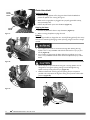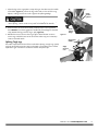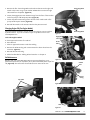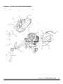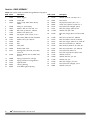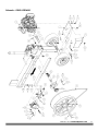
1
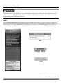
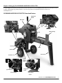
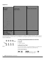
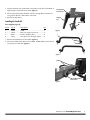
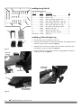
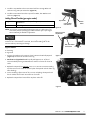
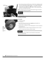
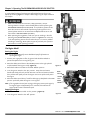
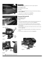
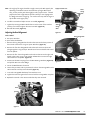
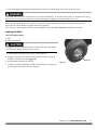
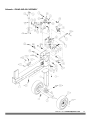
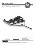
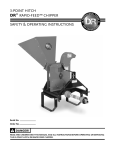
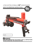
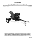
DR® PREMIER RAPIDFIRE™ LOG SPLITTER SAFETY & OPERATING INSTRUCTIONS Serial No. Order No. Original Language DR Power Equipment Toll-free phone: 1-800-DR-OWNER (376-9637) Fax: 1-802-877-1213 Website: www.DRpower.com Read and understand this manual and all instructions before operating the DR PREMIER RAPIDFIRE LOG SPLITTER. Table of Contents Chapter 1: General Safety Rules............................................................................................................................................................ 3 Chapter 2: Setting Up The DR PREMIER RAPIDFIRE LOG SPLITTER ................................................................................................ 7 Chapter 3: Operating The DR PREMIER RAPIDFIRE LOG SPLITTER ................................................................................................. 13 Chapter 4: Maintaining The DR PREMIER RAPIDFIRE LOG SPLITTER .............................................................................................. 16 Chapter 5: Troubleshooting .................................................................................................................................................................. 22 Chapter 6: Parts Lists and Schematic Diagrams .................................................................................................................................. 24 Conventions used in this manual This indicates a hazardous situation, which, if not avoided, could result in death or serious injury. This indicates a hazardous situation, which, if not avoided, could result in minor or moderate injury. This information is important in the proper use of your machine. Failure to follow this instruction could result in damage to your machine or property. Serial Number and Order Number A Serial Number is used to identify your machine and is located on the Serial Number Label on your machine. An Order Number is used to check and maintain your order history and is located on the upper left portion of your packing slip. For your convenience and ready reference, enter the Serial Number and Order Number in the space provided on the front cover of this manual. Additional Information and Potential Changes DR Power Equipment reserves the right to discontinue, change, and improve its products at any time without notice or obligation to the purchaser. The descriptions and specifications contained in this manual were in effect at printing. Equipment described within this manual may be optional. Some illustrations may not be applicable to your machine. 2 DR® PREMIER RAPIDFIRE™ LOG SPLITTER Chapter 1: General Safety Rules Read this Safety & Operating Instructions manual before you use the DR RAPIDFIRE LOG SPLITTER. Become familiar with the operation and service recommendations to ensure the best performance from your machine. If you have any questions or need assistance, please contact us at www.DRpower.com or call toll-free 1-800-DR-OWNER (376-9637) and one of our Technical Support Representatives will be happy to help you. Labels Your DR PREMIER RAPIDFIRE LOG SPLITTER carries prominent labels as reminders for its proper and safe use. Shown below are copies of all the Safety and Information labels that appear on the equipment. Take a moment to study them and make a note of their location on your LOG SPLITTER as you set up and before you operate the unit. Replace damaged or missing safety and information labels immediately. #35220 #25044 #13758 #35185 CONTACT US AT www.DRpower.com 3 Protecting Yourself and Those Around You This is a high-powered machine, with moving parts operating with high energy. You must operate the machine safely. Unsafe operation can create a number of hazards for you, as well as anyone else in the nearby area. Always take the following precautions when using this machine: Keep in mind that the operator or user is responsible for accidents or hazards occurring to other people, their property, and themselves. Always wear protective goggles or safety glasses with side shields while using the Log Splitter to protect your eyes from possible thrown debris. Avoid wearing loose clothing or jewelry, which can catch on moving parts. We recommend wearing gloves while using the Log Splitter. Be sure your gloves fit properly and do not have loose cuffs or drawstrings. Wear shoes with non-slip treads when using your Log Splitter. If you have safety shoes, we recommend wearing them. Do not use the machine while barefoot or wearing open toed sandals. Wear long pants while operating the Log Splitter. Use ear protectors or ear plugs rated for at least 20 dba to protect your hearing. Keep bystanders at least 50 feet away from your work area at all times. Stop the engine when another person or pet approaches. Safety for Children and Pets Tragic accidents can occur if the operator is not alert to the presence of children and pets. Children are often attracted to the machine and the splitting activity. Never assume that children will remain where you last saw them. Always follow these precautions: Keep children and pets at least 50 feet from the working area and ensure they are under the watchful care of a responsible adult. Be alert and turn the machine off if children or pets enter the work area. Never allow children to operate the Log Splitter. Safety with Gasoline - Powered Machines Gasoline is a highly flammable liquid. Gasoline also gives off flammable vapor that can be easily ignited and cause a fire or explosion. Never overlook the hazards of gasoline. Always follow these precautions: Never run the engine in an enclosed area or without proper ventilation as the exhaust from the engine contains carbon monoxide, which is an odorless, tasteless, and deadly poisonous gas. Store all fuel and oil in containers specifically designed and approved for this purpose and keep away from heat and open flame, and out of the reach of children. Replace rubber fuel lines and grommets when worn or damaged and after 5 years of use. Fill the gasoline tank outdoors with the engine off and allow the engine to cool completely. Don't handle gasoline if you or anyone nearby is smoking, or if you're near anything that could cause it to ignite or explode. Reinstall the fuel tank cap and fuel container cap securely. If you spill gasoline, do not attempt to start the engine. Move the machine away from the area of the spill and avoid creating any source of ignition until the gas vapors have dissipated. Wipe up any spilled fuel to prevent a fire hazard and properly dispose of the waste. Allow the engine to cool completely before storing in any enclosure. Never store a machine that has gas in the tank, or a fuel container, near an open flame or spark such as a water heater, space heater, clothes dryer or furnace. 4 DR® PREMIER RAPIDFIRE™ LOG SPLITTER Safety with Gasoline - Powered Machines (continued) Never tamper with the engine’s governor setting. The governor controls the maximum safe operation speed and protects the engine. Over-speeding the engine is dangerous and will cause damage to the engine and to the other moving parts of the machine. If required, see your authorized dealer for engine governor adjustments. Keep combustible substances away from the engine when it is hot. Never cover the machine while the muffler is still hot. Do not operate the engine with the air cleaner or the carburetor air intake cover removed. Removal of such parts could create a fire hazard. Do not use flammable solutions to clean the air filter. The muffler and engine become very hot and can cause a severe burn; do not touch. Safety with Electric - Powered Machines Never overlook the hazards of electricity. Always follow these precautions: Never open the switch box or motor cover. Never attempt any electrical repairs yourself. If in doubt, consult a qualified electrician, visit our website at www.DRpower.com or contact DR Power Equipment for toll-free support at: 1-800-dr-owner (376-9637) for help or information. Never use an extension cord that is not rated for outdoor use. Never operate the Log Splitter if there is an electrical hazard present. Never operate the Log Splitter in wet conditions and always store under cover. Never operate the Log Splitter with a damaged electrical cord or damaged extension cord. Never pull on the electrical cord to move the machine. Always grasp the electrical cord plug when unplugging the cord from the outlet; never pull the plug out by the cord. Make sure your fingers do not touch the metal prongs when plugging or unplugging. Never operate the Log Splitter unless the electrical cord is plugged into a properly grounded GFCI protected electrical outlet, which supplies 110-120v power, and is protected by a 20-amp circuit breaker. Never tamper with safety devices. Check their proper operation regularly. If you are using an extension cord, keep the connection between the electrical cord and the extension cord well away from any water. Never use an extension cord longer than 25 feet and smaller than 12 awg in diameter, or longer than 50 feet and smaller than 10 awg in diameter; the cord will produce a voltage drop that will prevent the motor from supplying full power and may cause damage to the motor. Use of a smaller diameter (larger awg number) extension cord could result in melting of the insulation or even create a fire. Always keep the electrical cord and/or extension cord away from excessive heat, oil, and sharp objects. Towing ALWAYS check before towing to make certain your Splitter is correctly and securely attached to the machine you are towing with. ALWAYS allow for added length of the Splitter behind you when turning, parking and in all towing situations. ALWAYS be careful when backing up. You could jackknife your Splitter if care is not taken. NEVER exceed 3 mph. when towing your Splitter. NEVER allow anyone to sit or ride on your Splitter. NEVER carry any cargo on your Splitter. Do travel slowly over rough terrain, on hillsides, and around curves to prevent tipping. Do not tow the Splitter near the edge of a ditch or excavation. CONTACT US AT www.DRpower.com 5 General Safety Operating this Log Splitter safely is necessary to prevent or minimize the risk of death or serious injury. Unsafe operation can create a number of hazards for you. Always take the following precautions when operating this Log Splitter: Your Log Splitter is a powerful tool, not a plaything. Exercise extreme caution at all times. The machine is designed to split logs. Do not use it for any other purpose. Know how to stop the Log Splitter quickly; see “stopping the engine” in chapter 3. Never operate your unit on a slippery, wet, muddy, or icy surface. Exercise caution to avoid slipping or falling. See manufacturer’s instructions for proper operation and installation of accessories. Only use accessories approved by DR Power Equipment. Never use the machine without ensuring that all guards and shields are in place. Never, under any conditions, remove, bend, cut, fit, weld, or otherwise alter standard parts on the Log Splitter. This includes all shields and guards. Modifications to your machine could cause personal injuries and property damage and will void your warranty. Allow only one person to operate the Log Splitter at any time. If the machine should start making an unusual noise or vibration, For Gas Engine: Shut down the engine, disconnect the spark plug wire, keeping it away from the spark plug to prevent accidental starting, For Electric Motor: Shut off the Motor, Unplug the Power Cord. Wait 5 minutes for machine to cool down then inspect for damage. Vibration is generally a warning of trouble. Check for damaged parts and clean, repair and replace as necessary. Never tamper with safety devices. Check their proper operation regularly. Before performing any maintenance or inspection procedure on the Log Splitter, For Gas Engine: Shut down the engine, disconnect the spark plug wire, keeping it away from the spark plug to prevent accidental starting, For Electric Motor: Shut off the Motor, Unplug the Power Cord. Wait 5 minutes for machine to cool down. Never allow people who are unfamiliar with these instructions to use the Log Splitter. Allow only responsible individuals who are familiar with these rules of safe operation to use your machine. Never overload or attempt to split logs beyond the recommendations listed in this manual. Personal injury or damage to the machine could result. While using the Log Splitter, don't hurry or take things for granted. When in doubt about the equipment or your surroundings, stop the machine and take the time to look things over. Never operate the machine when under the influence of alcohol, drugs, or medication. Use the machine only in daylight. Stay alert for hidden hazards or traffic. Keep all nuts and bolts tight and keep the equipment in good operating condition. A Note to All Users Under California law, and the laws of some other states, you are not permitted to operate an internal combustion engine using hydrocarbon fuels without an engine spark arrester. This also applies to operation on US Forest Lands. All DR PREMIER RAPIDFIRE LOG SPLITTERS shipped to California, New Mexico and Washington State are provided with spark arresters. Failure of the owner or operator to maintain this equipment in compliance with state regulations is a misdemeanor under California law and may be in violation of other state and/or federal regulations. Contact your State Park Association or the appropriate state organization for specific information in your area. No list of warnings and cautions can be all-inclusive. If situations occur that are not covered by this manual, the operator must apply common sense and operate this DR PREMIER RAPIDFIRE LOG SPLITTER in a safe manner. Contact us at www.DRpower.com or call 1-800-DR-OWNER (376-9637) for assistance. 6 DR® PREMIER RAPIDFIRE™ LOG SPLITTER Chapter 2: Setting Up The DR PREMIER RAPIDFIRE LOG SPLITTER It may be helpful to familiarize yourself with the controls and features of your DR PREMIER RAPIDFIRE LOG SPLITTER as shown in Figure 1 before beginning these procedures. If you have any questions at all, please feel free to contact us at www.DRpower.com. DR PREMIER RAPIDFIRE LOG SPLITTER Controls and Features Engagement Handle Belt Guard Safety Interlock Lever Flywheel Choke Lever Throttle Lever Belt Splitting Wedge Ram Gas Fill Cradle Starter Cord Frame Stand Pneumatic Tires Off Circuit Breaker Switch On Ignition Switch Gasoline Engine On/Off Switch Electric Motor Figure 1 CONTACT US AT www.DRpower.com 7 Specifications HP Output Torque Fuel Capacity Oil Capacity Voltage Full Load Current (Amps) Power (Watts) Hertz Phase Overload Protection Outlet Cord Frame Gauge Belt Size Ground Clearance Flywheel Weight (lbs.) Flywheel RPM Maximum Log Length Maximum Log Diameter Cycle Time (sec.) Splitting Force Wedge Height Wheel size Machine Height Machine Length w/ Table Machine Length w/out Table Machine Width Weight w/ Table (lbs.) Weight w/out Table (lbs.) GAS ENGINE ELECTRIC MOTOR 3 3.5 ft-lbs (4.7 N-m) .53 gal / 2.1 qt (2 L) .37 qt / 11.8 oz. (0.35L) - 0.5 1.47 ft-lbs (2 N-m) @ Full Load 115 6.7 360 60 1 Thermal Breaker 11" .25" 4L-750 3" 55 400 18" 30" 2.5 Out splits 22 ton Hydraulic 6.2" 4x11 46" 80" 62" 25" 285 235 .25" 4L-750 3" 55 400 18" 30" 2.5 Out splits 22 ton Hydraulic 6.2" 4x11 46" 80" 62" 25" 275 225 *The diameter listed is indicative of the maximum suggested size - a small log can be difficult to split when it contains knots or a particularly tough fiber. On the other hand, it may not be difficult to split logs with regular fibers even if its diameter exceeds the maximum indicated above. Assembling the DR PREMIER RAPIDFIRE LOG SPLITTER 2 1 Figure 2 Tools needed: Jack Stand Two 9/16" Wrenches Installing the Frame Stand The Frame Stand hardware is in the Product Package. Do not install the Frame Stand at this time if you have a Table accessory (install Table first). Hardware Supplied (Figure 2): Item # Part # Description Qty 1 ............. 32104 .............. Bolt, Carriage, 3/8-16 X 1", GR5, ZP......... 4 2 ............. 33333 .............. Nut, Nylon Lock, Flanged, 3/8-16 ............ 4 8 DR® PREMIER RAPIDFIRE™ LOG SPLITTER 1. Support the Beam with a Jack Stand or equivalent so the front of the Beam is high enough to install the Frame Stand (Figure 3). Carriage Bolt and Locknut 2. Secure the Support Leg to the Beam with four Carriage Bolts and Locknuts using a 9/16" Wrench. Bolt head on stand side. 3. Remove the Jack Stand. Beam Support Leg Installing the Cradle Kit Jack Stand Parts Supplied (Figure 2): Item # Part # Description Qty 1 ............. 34496 .............. Cradle..................................................... 2 2 ............. 33350 .............. Bolt, Hex, Flange, 3/8-16 X 2"............... 4 3 ............. 28551 .............. Washer, Saddle, 3/8 X 1" ...................... 4 4 ............. 33333 .............. Nut, Nylon Lock, Flanged, 3/8-16......... 4 Figure 3 1 1. Remove the Hardware from the Cradles (Figure 4). 2 3 2. Secure the Cradles to the Beam with the Bolts, Saddle Washers and Locknuts using two 9/16" Wrenches (Figure 5). 4 Figure 4 Cradles Bolt, Saddle Washer and Locknut Figure 5 CONTACT US AT www.DRpower.com 9 4 6 3 5 Installing the Log Table Kit Parts Supplied (Figure 6): Item # 10 9 8 7 1 Part # Description Qty 1 .................... 34503 ....... Bracket, Log Table .......................................1 2 .................... 32105 ....... Mount, Tray .................................................2 3 .................... 33351 ....... Bolt, Hex, Flange, 3/8-16 X 1.25"................4 4 .................... 22912 ....... Bolt, HHCS, 3/8-16 X 4.5", GR5, ZP ...........2 5 .................... 32104 ....... Bolt, Carriage, 3/8-16 X 1", GR5, ZP...........4 6 .................... 15043 ....... Bolt, HHCS, 3/8-16 X 1-1/4", ZP ................4 7 .................... 33333 ....... Nut, Nylon Lock, Flanged, 3/8-16...............10 8 .................... 18081 ....... Washer, Lock, 3/8" ......................................4 9 .................... 11239 ....... Washer, Flat, 3/8", USS ..............................2 10 .................. 11241 ....... Washer, Flat, 5/16" USS, ZP .......................4 Not Shown.... 31363 ....... Table, Log ....................................................1 Installing Log Table with Support Leg 1. Place a Jack Stand under the Beam to lift it up. 2 2. Loosely install a Tray Mount on both side of the Beam with Flange Bolts and Locknuts using two 9/16" Wrenches (Figure 7). 3. Install the front of the Tray to the Beam with four Bolts, Flat Washers and Lock Washers using a 9/16" Wrench (Figure 8). Figure 6 4. Install the Table to the Tray Mounts with four Carriage Bolts and Locknuts using a 9/16" Wrench (Figure 9). Bolts and Locknuts Carriage Bolt and Locknut Tray Mount Figure 7 Tray Mounts Table Beam Figure 8 10 Bolt, Lock Washer and Flat Washer DR® PREMIER RAPIDFIRE™ LOG SPLITTER Figure 9 5. Install the Tray Bracket to the Frame Stand with four Carriage Bolts and Locknuts using two 9/16" Wrenches (Figure 10). 6. Install the Frame Stand onto the Tray with four Bolts, Flat Washers and Locknuts (Figure 11). Adding Oil and Gasoline (gas engine model) Engine Oil Fuel See Engine Manual for specific Engine capacities and specifications Unleaded gasoline NOTE: Use only the recommended high detergent engine oil. Other types of oil could cause problems operating your machine. Please refer to your Engine Owner’s Manual for detailed oil information. Tray Bracket Carriage Bolts and Locknuts Frame Stand Figure 10 Support Leg with Tray Bracket The Engine must be level to get an accurate reading when adjusting the amount of oil. If the machine is not level, the oil level reading will not be accurate and may cause engine damage. Bolt, Flat Washer and Locknut Supplies Needed: Clean Rag Engine Oil 1. Position the machine so the Engine is level. Remove the Oil Fill/Dipstick (Figure 12) and clean the end of it with a rag. Figure 11 2. Machines are shipped with no oil. Initially add approx, 8 oz. of the oil recommended by the Engine Manufacturer. Wait one minute for the oil to settle. 3. Replace the Dipstick, but DO NOT screw it in to ensure an accurate reading and then remove it to check the oil level (clean the Dipstick with the clean rag after checking). 4. Continue adding a few ounces of oil at a time, rechecking the Dipstick until the oil reaches the fill mark. Be careful not to overfill. 5. Replace the Dipstick and screw all the way down when full. Oil Dipstick Figure 12 CONTACT US AT www.DRpower.com 11 Gas Cap 6. Remove the Gas Fill Cap and fill the Gas Tank with fresh, unleaded gas (with a minimum of 85 Octane) to approximately 1" to 1-1/2" below the top of the fill neck to allow for fuel expansion (Figure 13). Be careful not to overfill. Install the Gas Fill Cap before starting the engine. See your Engine Owner’s Manual for more detailed information. NOTE: To refill the gas tank, turn the engine OFF and let the engine cool at least five minutes before removing the gas fill cap. We highly recommend the use of fuel treatments in your fuel to prevent Carburetor fouling. Figure 13 Check the Tire Pressure Tools Needed: Tire Pressure Gauge Air Compressor 1. Remove the Valve Stem Protective Cap (Figure 14) and check the tire pressure with a Tire Pressure Gauge. Valve Stem Protective Cap 2. Check what the manufacturers recommended pressure is that is stamped on the side of the Tire. 3. If the pressure is too low, add air through the Valve Stem with an air hose. 4. Replace the Valve Stem Protective Cap when finished. Figure 14 Do not over inflate the tires. Inflate to the manufacturers recommended pressure found on the tires. 12 DR® PREMIER RAPIDFIRE™ LOG SPLITTER Chapter 3: Operating The DR PREMIER RAPIDFIRE LOG SPLITTER It may be helpful to better familiarize yourself with the features of your Log Splitter by reviewing Figure 1 in Chapter 2 before beginning the steps outlined in this chapter. Read and understand all instructions, safety precautions, and/or warnings listed in “Chapter 1 General Safety Rules” before operating this DR PREMIER RAPIDFIRE LOG SPLITTER. If any doubt or question arises about the correct or safe method of performing anything found in this manual, please contact our Customer Service Representatives at our toll free number: 1-800-DR-OWNER (376-9637). When operating the Log Splitter, make sure you are standing in the safe operating area (OPERATOR ZONE) as shown in Figure 15. You must stay in the safe operating area at all times when the ram is in motion (whether extending or retracting). Never place any part of your body into a position that causes an unsafe operating condition. Operator Zone Gas Engine Model Starting the Engine Note: See the Engine Manual for more detailed and specific information on operating the Engine. TOP VIEW 1. Position your Log Splitter on flat, dry ground and chock the Wheels to prevent the Splitter from moving during use. 2. Move the choke control lever to the CHOKE position to the right (should only be needed if the engine is cold) (Figure 16). Figure 15 3. Move the throttle control lever to the FAST “Rabbit” position. 4. Turn the Ignition Switch to the “On” position. Grasp the recoil starter handle and slowly pull until you feel resistance. Let the cord retract a little bit then pull the cord rapidly to start the engine. One or two pulls usually starts the engine. 5. Move the choke control lever (if used for cold engine) slowly back to the RUN position (to the left) when the engine is running well. Note: If the Log Splitter has not been running (cold engine), warm up the engine by running the engine at half throttle for 3 to 4 minutes, then advance the engine throttle control to maximum speed. Choke Lever Throttle Lever Off Starter Handle On Engine Switch Stopping the Engine 1. Move the Throttle Lever to Idle “Turtle” position ((Figure 16). 2. Turn the Ignition Switch to the “Off” position. Figure 16 CONTACT US AT www.DRpower.com 13 Electric Motor Model Circuit Breaker Switch Starting the Motor 1. Position your Log Splitter on flat, dry ground and chock the Wheels to prevent the Splitter from moving during use. 2. Make sure the Log Splitter is plugged into a properly grounded 15 Amp, GFCI protected outlet. 3. Pull the On/Off Switch up to start the Motor (Figure 17). On/Off Switch Figure 17 Stopping the Motor 1. Push the On/Off Switch down to stop the Motor (Figure 17). 2. When not using the Splitter unplug the Cord. Splitting Note: All logs should be no longer than 18". Use the following photos for the correct and incorrect methods of splitting logs. Never split a log using an incorrect or unsafe method. Do not place your hands on the ends of the log when loading the Log Splitter. This is a very UNSAFE method and could result in injury to your hands (Figure 18). Do not reach or step across the beam while the Log Splitter is running. This is a very UNSAFE method which could cause personal injury or even death. Figure 18 Never attempt to split wood across the grain. The Log Splitter was not designed for cross-grain splitting. Doing so could damage the Log Splitter and may cause personal injury (Figure 19). Make sure both ends of the log you are splitting are cut as square as possible. This will prevent the log from sliding out of position while under pressure (Figure 20). Figure 19 Figure 20 14 DR® PREMIER RAPIDFIRE™ LOG SPLITTER 1. Place the log on the Log Splitter. Grasp the log on the sides near the middle of the block (Figure 21). Center the log, side-to-side, on the rail of the Log Splitter, making sure that one end is against the Splitting Wedge. Hands on Sides of Wood The engagement Handle must be held fully forward against the hard stop when splitting. Failure to do so may result in kickback of the Handle. 2. With one hand, lift and hold the Safety Interlock Lever in the up position then RAPIDLY move the Engagement Handle fully forward against the hard stop (towards the log) until the Log is split (Figure 22). 3. Release the Lever as soon as the Log is split to allow the Ram to return. Continuing to hold the Lever at the end of the stroke may put unnecessary stress on the Rack Teeth. Wood Against Wedge Figure 21 Engagement Handle Splitting Tough Logs If the Ram stops before the end of the stroke while splitting a tough Log, quickly push the Lever back to prevent stress on the Belts. Let the Ram return and the Flywheels to gain momentum to allow for another full power split. Safety Interlock Lever 2 1 Figure 22 CONTACT US AT www.DRpower.com 15 Chapter 4: Maintaining The DR PREMIER RAPIDFIRE LOG SPLITTER Regular maintenance is the way to ensure the best performance and long life of your machine. Please refer to this manual and the engine manufacturer's owner's manual for maintenance procedures. Service intervals listed in the checklist below supersede those listed in the engine manufacturer's owner's manual. Before performing any maintenance procedure or inspection, stop the engine, wait five minutes to allow all parts to cool. Disconnect the spark plug wire, keeping it away from the spark plug. Regular Maintenance Checklist PROCEDURE BEFORE EACH USE Check Engine Oil Level Check General Equipment Condition Perform Rail Maintenance Check Belt Check the condition of the electrical cord. Grease Rack Grease Engagement Fittings Check Tire Pressure Clean Engine Exterior and Cooling Fins Change Engine Oil Replace Air Filter Replace Spark Plug EVERY 5 HOURS EVERY 10 HOURS EVERY 25 HOURS EVERY 100 HOURS ▲ ▲ ▲ ▲ ▲ ▲ ▲ 1st time 5 hours ▲ ▲ ▲ ▲ ▲ Engine Service Refer to the engine manufacturer’s manual for engine maintenance. Lubrication All Bearings of your Splitter are sealed units and should have sufficient lubricant to last the life of your machine with normal use. Perform machine lubrication per the following instructions. Safety Interlock Lever Greasing the Engagement Fittings Short Flange Bolts Left Side Guard Short Flange Bolts Two 9/16" Wrenches 9/16" Socket and Ratchet Extended Hose Grease Gun with all Purpose Grease Clean Rags 1. Remove the long Flange Bolt and Locknut that secures the lower portion of the Guards to the Frame using two 9/16" Wrenches (Figure 23). Long Flange Bolt Figure 23 16 Tools and Supplies needed: DR® PREMIER RAPIDFIRE™ LOG SPLITTER 2. Remove the five short Flange Bolts and Locknuts that secure the Guard Flanges together using two 9/16" Wrenches and remove the left side Guard from the Splitter. Short Flange Bolts 3. Remove the four short Flange Bolts and Locknuts that secure the right side Guard to the Frame using a 9/16" Socket and Ratchet to remove the right side Guard from the Splitter (Figure 24). 4. Grease the Engagement Lever Grease Fittings from the front of the machine with a few pumps of All Purpose Grease (Figure 25). 5. Grease the Yoke Grease Fittings from the rear of the machine with a few pumps of All Purpose Grease (Figure 26). Right Side Guard 6. Reinstall the Guards in the reverse order that they were removed. Changing Engine Oil (Gas Engine Model) One of the easiest methods to remove oil from this Engine is to use a siphon style Oil Extractor. If you do not have one you can purchase it from us at www.DRpower.com. Tools and Supplies needed: Clean Approved Container for used Oil 10mm Wrench 1. Place an approved Container under the Oil Plug. Short Flange Bolts Figure 24 Engagement Lever Grease Fitting 2. Remove the Oil Drain Plug with a 10mm Wrench to drain the Oil into the Container (Figure 27). 3. Reinstall the Oil Drain Plug. 4. Add oil as described in “Adding Oil and Gasoline” in Chapter 2. Rail Maintenance Between each use of the LOG SPLITTER, we recommend applying a rust preventative (Fluid Film or equivalent) to any bare metal areas on the top of the rail (Figure 28). This will assure the smoothest return action of the ram. Figure 25 Handle Yoke Grease Fitting Top of Rail Figure 26 Figure 28 Drain Plug Oil Dipstick Figure 27 CONTACT US AT www.DRpower.com 17 Greasing the Rack It is important to grease the Rack every 5 hours for proper operation. Tools and Supplies needed: Ram Bearing Spring General Purpose Lithium Grease Clean Rags 1. Pull out the Ram and slide both return Spring ends from the Ram Bearing hardware (Figure 29). 2. Pull the Rack out and grease the Teeth (Figure 30). Figure 29 3. Reinstall the Spring ends when finished greasing. Changing and Adjusting the Belt Tools and Supplies needed: Two 9/16" Wrenches DR Belt Rack Teeth 1. Remove the long Flange Bolt and Locknut that secures the lower portion of the Guards to the Frame using two 9/16" Wrenches (Figure 31). Figure 30 2. Remove the five short Flange Bolts and Locknuts that secure the Guard Flanges together using two 9/16" Wrenches and remove the left side Guard from the Splitter. Safety Interlock Lever Short Flange Bolts 3. Loosen the front two Engine Mount Pivot Bolts and Locknuts with two 9/16" Wrenches (Figure 32). 4. Loosen the rear two Angle Setting Bolts with Flat Washers using two 9/16" Wrench. 5. Pivot the Mount up slightly and remove the Belt (Figure 33). Left Side Guard Short Flange Bolts Long Flange Bolt Figure 31 Loosen Belt Flywheel Pulley Tighten Angle Belt Setting Bolts Engine Mount Pivot Bolts Figure 32 18 DR® PREMIER RAPIDFIRE™ LOG SPLITTER Figure 33 Belt Note: The weight of the Engine should be enough to tension the Belts properly but depending on hardware looseness and cleanliness of Engine Mount pivot area, you may need to push down slightly to aid in proper tension. The Belt performs best with a slight amount of slack to allow for some slippage when the Wedge encounters a tough log. Too much tension may stall the engine or slip the belt on the engine pulley. Safety Interlock Lever Left Side Guard 6. Install the new Belt and adjust tension as needed (Figure 33). 7. Tighten the two Engine Mount Bolts that are at the center of the machine (shown) first and then tighten the outer two Bolts (Figure 32). Short Flange Bolts 8. Reinstall the Guard (Figure 31). Short Flange Bolts Adjusting the Rack Alignment Figure 34 Tools needed: Long Flange Bolt Short Flange Bolts Two 9/16" Wrenches 9/16" Socket and Ratchet 1. Remove the long Flange Bolt and Locknut that secures the lower portion of the Guards to the Frame using two 9/16" Wrenches (Figure 34). 2. Remove the five short Flange Bolts and Locknuts that secure the Guard Flanges together using two 9/16" Wrenches and remove the left side Guard from the Splitter. Right Side Guard 3. Remove the four short Flange Bolts and Locknuts that secure the right side Guard to the Frame using a 9/16" Socket and Ratchet to remove the right side Guard from the Splitter (Figure 35). 4. Disconnect the Return Springs from the Ram Bearing Hardware (Figure 36) and pull the Ram out to the Wedge. Short Flange Bolts Figure 35 5. Center the Rack between the Frame. 6. Loosen the Jam Nuts with a 9/16" Wrench and turn the Carriage Bolts with a 10mm Wrench until they touch the Rack (Figure 37). 7. Turn each Carriage Bolt back away from Rack two turns. 8. Tighten the Locknuts against the Frame to lock the Carriage Bolts into place. 9. Replace the Guards in the reverse order that they were removed. Spring Ram Bearing Carriage Bolts Jam Nut Frame Jam Nut Figure 36 Rack Figure 37 CONTACT US AT www.DRpower.com 19 Adjusting the Steel Bushing Over Center Tools needed: Safety Interlock Lever Short Flange Bolts 1. Remove the long Flange Bolt and Locknut that secures the lower portion of the Guards to the Frame using two 9/16" Wrenches (Figure 38). 2. Remove the five short Flange Bolts and Locknuts that secure the Guard Flanges together using two 9/16" Wrenches and remove the left side Guard from the Splitter. Left Side Guard Short Flange Bolts Two 9/16" Wrenches 9/16" Socket and Ratchet Long Flange Bolt Figure 38 Short Flange Bolts Right Side Guard 3. Remove the four short Flange Bolts and Locknuts that secure the right side Guard to the Frame using a 9/16" Socket and Ratchet to remove the right side Guard from the Splitter (Figure 39). 4. Loosen the Stop Bolt Jam Nuts (Figure 40). 5. Lift the Safety Interlock Lever and push the Engagement Handle forward to position the Steel Bushing Yoke as close to vertical as you can and hold it there (Figure 41). 6. Rotate the Stop Bolts until they touch the Steel Bushing Yoke. Turn the Bolt back out of the Frame counterclockwise 1-1/4 revolutions. Tighten the Jam Nuts with a 9/16" Wrench to lock the Stop Bolts at this position. Do not adjust more than 1-1/4 revolutions when adjusting off center. Adjustment too far off center will not allow the Rack Teeth to engage fully and will cause damage to the Splitter. Short Flange Bolts Figure 39 Over Center Position Vertical Position Forward Stop Adjustment Handle Yoke Steel Bushing Jam Nuts Pinion Rack Stop Bolts Figure 40 20 DR® PREMIER RAPIDFIRE™ LOG SPLITTER Back of Yoke Figure 41 7. Push the Engagement Handle all the way forward to confirm the Steel Bushing Yoke is moving just past center. The Handle Yoke must move just past center as it contacts the Bolt Stop. If it is at the center position, or off center in the wrong direction, the force of splitting a log will be transferred through the Engagement Handle and could cause injury. When using the Splitter for the first time after this adjustment, split smaller diameter logs with no knots to verify that the adjustments are correct before trying larger diameter tougher logs. If you have any questions please contact us at www.DRpower.com or call 1-800-DR-OWNER (376-9637) for assistance. Replacing the Wheels Tools and Supplies needed: Pliers Jack and Jack Stands The Splitter must be supported carefully so it does not tip over when jacking or it could cause Splitter damage or personal injury. 1. Jack the Splitter off the ground and secure with Jack Stands. 2. Straighten the ends of the Cotter Pin with Pliers so the Cotter Pin can be pulled from the hole in the Axle (Figure 42). 3. Pull the Wheel assembly from The Axle. 4. Install the new/repaired Wheel Assembly and secure with a new Cotter Pin by bending the ends of the Cotter Pin with Pliers. Cotter Pin Figure 42 CONTACT US AT www.DRpower.com 21 Chapter 5: Troubleshooting Most problems are easy to fix. Consult the Troubleshooting Table below for common problems and their solutions. If you continue to experience problems, contact us at www.DRpower.com or call toll-free 1-800-DR-OWNER (376-9637) for support. Before performing any maintenance procedure or inspection, stop the engine, wait five minutes to allow all parts to cool. Disconnect the spark plug wire, keeping it away from the spark plug. Troubleshooting Table SYMPTOM POSSIBLE CAUSE The gas engine won’t start. Is the ignition switch in the “On” position? Are you using fresh, clean gas? If the gas is old, change it. Use a fuel stabilizer if you keep gas longer than 30 days. Is the spark plug clean? If the spark plug is dirty or cracked, change it. If it’s oily, leave it out, hold a rag over the plug hole and pull the recoil cord several times to blow out any oil in the cylinder, then wipe off the plug and reinsert it. If your engine still won’t start, contact us at www.DRpower.com for assistance. (Please refer to the engine owner’s manual for engine-specific procedures.) The gas engine lacks power or is not running smoothly. (Please refer to the engine owner’s manual for engine-specific procedures.) Gas Engine smokes. (Please refer to the engine owner’s manual for engine-specific procedures.) With Motor running and the handle is pushed, the wedge does not move or is slow to respond. 22 Check that the Throttle Lever is in the “Run” position and the Choke is off. Is the air filter clean? If it’s dirty, change it following the procedure in the engine manufacturer’s owner’s manual. Is the spark plug clean? If it’s fouled or cracked, change it. If it’s oily, leave it out, hold a rag over the plug hole and pull your recoil cord several times to blow out any oil in the cylinder, then wipe off the plug and reinsert it. Are you using fresh, clean unleaded gas? If it’s old, change it. Use a fuel stabilizer if you keep gas longer than 30 days. Does your engine have the right amount of clean oil? If it’s dirty, change it following the procedure in the engine manufacturer’s owner’s manual. Check the oil level and adjust as needed. If your engine still lacks power, contact us at www.DRpower.com for assistance. The choke may still be on; Move the choke lever to the open position. Check the oil level and adjust as needed. Check the air filter and clean or replace if needed. You may be using the wrong oil—too light for the temperature. Refer to your Engine Owner’s Manual for detailed information. Clean the cooling fins if they’re dirty. If the engine still smokes, contact us at www.DRpower.com for assistance. Make sure the voltage at the outlet or extension cord connection to the Splitter is 110120VAC. If you are using an extension cord, make sure that the cord is no more than 25 feet long, is not smaller than 12 AWG wire or no more than 50 feet long, and is not smaller than 10 AWG wire. If the Wedge will still not move or is slow to respond, Visit our website at www.DRPower.com, or call 1-800-DR-OWNER (376-9637) for assistance. DR® PREMIER RAPIDFIRE™ LOG SPLITTER Troubleshooting Table (Continued) Before performing any maintenance procedure or inspection, stop the engine, wait five minutes to allow all parts to cool. Disconnect the spark plug wire, keeping it away from the spark plug. SYMPTOM POSSIBLE CAUSE The Motor does not run Splitter unplugged; plug Splitter in. Splitter Cord may be damaged; visit our website at www.DRPower.com or call 1-800-DROWNER (376-9637) for assistance. The motor Reset has tripped; push the Reset Button. If the above causes are not the problem, a circuit breaker might need to be reset; Reset Circuit Breaker. If the Motor still does not run, visit our website at www.DRPower.com or call 1-800-DROWNER (376-9637) for assistance. Log fails to split. Incorrect positioning of the log; re-position the log flat on the splitting beam with the end squarely against the Wedge. Log exceeds permitted dimensions or the wood is too hard for the capacity of the machine. The maximum log length is 18" with a maximum diameter of 30" for the Splitter Rack returning very slow or not returning properly. Check for wood chips or debris between ram bushing plate and beam. Clean beam of built up/caked on debris. Check rack lift bearing for alignment or damage. Return spring is unhooked or damaged. Reconnect or replace as needed. Operator Lever snapping out of gear or not staying in gear. Lever not all the way forward when rack comes under full load. Push lever quicker and more forcefully into the full forward position. A hard stop should be felt at the end of the stroke when engaging the handle. Stop bolts may be bent or not adjusted properly; contact us at www.DRpower.com for assistance. Ram has been overloaded at lower part of face. Check rack gear for straightness. Rack slamming back too fast. Wedge end of machine too high. Must be almost level with ram end or just slightly higher. Springs not operating properly. Fix or replace as needed. Machine does not seem to have full splitting power. The belt may be too loose and slipping. Adjust or replace belt as needed. Operator Lever not engaging rack with pinion gear. Clean wood chips or other debris from under rack. Clean accumulated dirt from frame where carriage assembly rests against rubber bumpers. Rack not disengaging from pinion when handle is released Belt must be loosened to allow for slipping while disengaging CONTACT US AT www.DRpower.com 23 Chapter 6: Parts Lists and Schematic Diagrams Parts List – FRAME STAND AND GUARD ASSEMBLY NOTE: Part numbers listed are available through DR Power Equipment. Ref# Part# Description Ref# Part# Description 1 2 3 4 5 6 7 Stand, Frame Guard, RH, With Labels Label, Warning, Pinch Point, 3.5" X 1" Label, DR Logo, 5" Diameter Guard, LH, With Labels Label, Branding Label, Operation, Warning, Caution 8 9 10 11 12 13 14 Cradle Bolt, Hex, Flange, 3/8-16 X 2" Washer, Saddle, 3/8" X 1" Nut, Nylon Lock, Flanged, 3/8-16 Bolt, Carriage, 3/8-16 X 1", GR5, ZP Bolt, Hex, Flange, 3/8-16 X .75", GR5, ZP Bolt, HCS, 3/8-16 X 8 1/2", GR5, ZP 24 34497 35178 25044 35187 35179 35186 35185 DR® PREMIER RAPIDFIRE™ LOG SPLITTER 34496 33350 28551 33333 32104 34512 34513 Schematic – FRAME STAND AND GUARD ASSEMBLY CONTACT US AT www.DRpower.com 25 Parts List – DRIVE ASSEMBLY NOTE: Part numbers listed are available through DR Power Equipment. Ref# Part# Description Ref# Part# Description 1 2 3 34493 34500 34507 4 5 6 7 8 9 10 11 12 13 14 15 34508 16514 17882 11243 10638 30245 11241 34505 32107 34492 32099 32111 22 23 24 25 26 27 28 29 32122 34491 29494 29493 33333 33351 112391 33358 16 33346 17 18 19 20 21 29468 35183 32125 29455 29456 Mount, Engine Guard, Belt Engine, 3.5tq, 100cc, Rato, Ms, W/ Labels Pulley, 4L, 3/16" Keyway Washer, .385" ID, 1.39" OD, .15" t Bolt, HCS, 5/16-24 X 1", GR2 ZP Washer, Lock, Split, 5/16" Key, Square, 3/16" X 3/16" X 1.5" L Bolt, HHCS, M8-1.25 X 30, Class8 ZP Washer, Flat, 5/16" USS, ZP Belt Ram Gear, Rack Bracket, Rack, Lifter Bearing, 6301, 12mm ID, 37mm OD, 12mm W Bushing, Bronze, 0.5" ID, 0.625" OD, 0.375" l Spring, Compression, Carriage Spring, Extension, Carriage, Return Flywheel, 55lb Housing, Bearing Insert Bearing W/ Snap Ring 30 31 32 33 34 35 36 37 38 39 40 41 42 43 31238 33354 34512 12321 12336 13443 30253 18755 11242 23499 11238 33349 33335 18081 Washer, 5/16" ID, 2.0" OD, 0.13" t Gear, Pinion Key, Square, 3/8" X 3/8" X 1.5" L Screw, Set, Cup Point, 3/8-16 X .5" L Nut, Nylon Lock, Flanged, 3/8-16 Bolt, Hex, Flange, 3/8-16 X 1.25" Washer, Flat, 3/8", USS Bolt, Hex, Flange, M12-1.75 X 50, CL 8.8, ZP Bolt, HCS, 1/2-20 X 2.5", GR8, ZP Bolt, HCS, M12-1.75 X 30, CL 8.8, ZP Bolt, Hex, Flange, 3/8-16 X .75", GR5, ZP Bolt, HCS, 5/16-18 X 3/4", GR5, ZP Bolt, HHCS, 5/16-18 X 1.25", GR5, ZP Bolt, HCS, 5/16-18 X 1-1/2", GR5, ZP Nut, Nylon Lock, M12-1.75 Nut, Lock, 5/16-18, Thin Nylon Insert Washer, Lock, 0.5" Washer, SAE Flat, 1/2", ZP Washer, Flat, 1/4" Bolt, Hex, Flange, 1/2-13 X 5" Nut, Nylon Lock, Flanged, 1/2-13 Washer, Lock, 3/8" 26 DR® PREMIER RAPIDFIRE™ LOG SPLITTER Schematic – DRIVE ASSEMBLY CONTACT US AT www.DRpower.com 27 Parts List – FRAME AND AXLE ASSEMBLY NOTE: Part numbers listed are available through DR Power Equipment. Ref# Part# Description Ref# Part# Description 1 2 3 4 35176 34494 34495 34501 5 6 7 8 9 10 11 12 13 14 15 16 17 18 19 11241 32126 29498 32106 32109 32098 11022 33355 10189 10948 33350 33333 33351 18081 33335 Frame, Main, With Labels Axle Support, Frame Wheel, Pneumatic, Turf Saver Tread, 11 X4 Washer, Flat, 5/16" USS, ZP Bracket, Return, Stop Cylinder, Bumper Catch, Handle Engagement Lever, 2 Hand Bushing, Bronze, SAE 954 Grip, Shift Handle Grip, Foam, 1" Tube, 5.1" Long Grease Fitting, 1/4-28 Straight Cap, Round 1" Bolt, Hex, Flange, 3/8-16 X 2" Nut, Nylon Lock, Flanged, 3/8-16 Bolt, Hex, Flange, 3/8-16 X 1.25" Washer, Lock, 3/8" Nut, Nylon Lock, Flanged, 1/2-13 20 21 22 23 24 25 26 27 28 29 30 31 32 33 34 35 36 33349 34511 23103 34512 18085 12683 33331 25311 35223 35225 35224 35237 35238 35240 35357 22909 35358 37 38 35359 11242 Bolt, Hex, Flange, 1/2-13 X 5" Bolt, Hex, Flange, 1/2-13 X 3", GR5, ZP Bolt, Carr, 3/8-16 X 1-3/4", GR5, ZP Bolt, Hex, Flange, 3/8-16 X .75", GR5, ZP Bolt, HCS, 1/4-20 X 2.75" Nut, 3/8-16, ZP Nut, Nylon Lock, Flanged, 1/4-20 Pin, Cotter, 5/32" X 2" Handle Yoke, Handle Link, Handle Bushing, Roller Bracket, Control Interface Spring, Torsion Bolt, HCS, 1/2-13 X 2", GR8, ZP Bolt, HCS, 1/2-13 X 1-1/2", GR5, ZP Bolt, Hex Tap Bolt, Fully Threaded, 3/816 X 3-1/2", GR8, ZP Nut, Hex, Jam, 1/2-13, GR5, ZP Washer, Lock, 0.5" 28 DR® PREMIER RAPIDFIRE™ LOG SPLITTER Schematic – FRAME AND AXLE ASSEMBLY CONTACT US AT www.DRpower.com 29 Parts List – TRAY KIT ASSEMBLY NOTE: Part numbers listed are available through DR Power Equipment. Ref# Part# Description 1 2 3 4 5 6 Table, Log Bracket, Log Table Mount, Tray Bolt, HHCS, 3/8-16 X 4.5", G5, ZP Washer, Flat, 3/8, USS Nut, Nylon Lock, Flanged, 3/8-16 30 31363 34503 32105 22912 11239 33333 DR® PREMIER RAPIDFIRE™ LOG SPLITTER Ref# Part# 7 8 9 10 11 32104 15043 18081 11241 33351 Description Bolt, Carriage, 3/8-16 X 1", GR5, ZP Bolt, HHCS, 3/8-16 X 1-1/4", GR5 Washer, Lock, 3/8" Washer, Flat, 5/16 USS, ZP Bolt, Hex, Flange, 3/8-16 X 1.25" Notes: CONTACT US AT www.DRpower.com 31 Daily Checklist for the DR PREMIER RAPIDFIRE LOG SPLITTER To help maintain your DR PREMIER RAPIDFIRE LOG SPLITTER for optimum performance, we recommend you follow this checklist each time you use your Log Splitter. Before performing any maintenance procedure or inspection, stop the engine, wait five minutes to allow all parts to cool. Disconnect the spark plug wire, keeping it away from the spark plug. [ [ [ [ [ [ [ ] ] ] ] ] ] ] Check the Engine Oil and Gas Tank level. Check that Engine is clean of debris. Check the general condition of the Log Splitter, e.g.; Nuts, Bolts, Welds, etc. Check Tire Pressure and wear. Check the Frame for wear and damage. Check the Wedge for nicks and wear. Sharpen if needed. Apply a rust preventative (Fluid Film or equivalent) to any bare metal areas on the top of the Rail. This will assure the longest possible service life of the Wedge. End of Season and Storage Before performing any maintenance procedure or inspection, stop the engine, wait five minutes to allow all parts to cool. Disconnect the spark plug wire, keeping it away from the spark plug. Change the Engine Oil. Clean or replace the Air Filter. Check the Wedge for nicks and wear. Sharpen if needed. Apply Grease to the Rack and Pinion Teeth. Apply a rust preventative (Fluid Film or equivalent) to any bare metal areas on the top of the Rail. If your DR PREMIER RAPIDFIRE LOG SPLITTER will be idle for more than 30 days, we recommend using a gas stabilizer. This will prevent sediment from gumming up the Carburetor. If there is dirt or moisture in the gas or Tank, remove it by draining the Tank. Completely fill the Tank with fresh, unleaded gas and add the appropriate amount of stabilizer or gasoline additive. Run the Engine for a short time to allow the additive to circulate. Clean the exterior of the unit to remove all dirt, grease, and any other foreign material. Clean dirt and debris from the Cylinder Head Cooling Fins and Muffler area of the Engine. To prevent rust, touch up painted surfaces that have been scratched or chipped. Be sure all Nuts, Bolts, and Screws are securely fastened. Remove the Spark Plug and pour about 1 ounce of Motor Oil into the Cylinder hole. Replace the Plug and crank the Engine over a couple of times using the Pull Cord. This will coat the Piston and seat the Valves to prevent moisture buildup. If possible, store the Log Splitter in a dry, protected place. If it is necessary to store the Log Splitter outside, cover it with a protective material (especially the Engine). 75 MEIGS ROAD, P.O. BOX 25, VERGENNES, VERMONT 05491 ©2014 Country Home Products, Inc. All rights reserved 351721