1
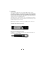
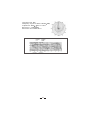
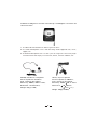
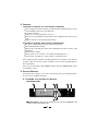
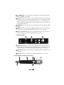
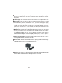
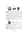
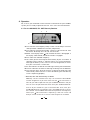
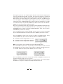
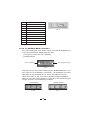
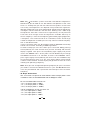
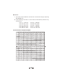
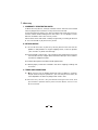
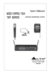
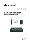
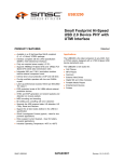
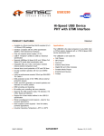
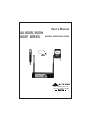
User's Manual
AU-800R/800H
800P SERIES
WIRELESS MICROPHONE SYSTEM
R
LTO
www.altoproaudio.com
Version 1.2 Oct. 2006
English
SAFETY RELATED SYMBOLS
CAUTION
RISK OF ELECTRIC SHOCK
DO NOT OPEN
The symbol is used to indicate that some
hazardous live terminals are involved
within this apparatus, even under the
normal operating conditions.
The symbol is used in the service documentation to indicate that specific
component shall be only replaced by
the component specified in that documentation for safety reasons.
Protective grounding terminal.
Alternating current /voltage.
Hazardous live terminal .
ON: Denotes the apparatus turns on.
OFF: Denotes the apparatus turns off, because of using the single pole switch, be sure
to unplug the AC power to prevent any electric shock before you proceed your service.
WARNING: Describes precautions that
should be observed to prevent the danger
of injury or death to the user.
Disposing of this product should
not be placed in municipal waste
and should be separate collection.
CAUTION: Describes precautions that
should be observed to prevent danger of the
apparatus.
WARNING
Power Supply
Ensure the source voltage matches the
voltage of the power supply before turning
ON the apparatus.
Unplug this apparatus during lightning
storms or when unused for long periods
of time.
External Connection
The external wiring connected to the output hazardous live terminals requires
installation by an instructed person, or
the use of ready-made leads or cords.
Do not Remove any Cover
There are maybe some areas with high
voltages inside, to reduce the risk of electric
shock, do not remove any cover if the power
supply is connected.
The cover should be removed by the qualified personnel only.
No user serviceable parts inside.
Fuse
To prevent a fire, make sure to use fuses
with specified standard (current, voltage,
type). Do not use a different fuse or short
circuit the fuse holder.
Before replacing the fuse, turn OFF the
apparatus and disconnected the power
source.
Protective Grounding
Make sure to connect the protective
grounding to prevent any electric shock
before turning ON the apparatus.
Never cut off the internal or external protective grounding wire or disconnect the
wiring of protective grounding terminal.
Operating Conditions
This apparatus shall not be exposed to
dripping or splashing and that no objects
filled with liquids, such as vases, shall be
placed on this apparatus.
To reduce the risk of fire or electric shock,
do not expose this apparatus to rain or
moisture.
Do not use this apparatus near water.
Install in accordance with the manufacturer's
instructions. Do not install near any heat
sources such as radiators, heat registers,
stoves, or other apparatus (including amplifiers) that produce heat. Do not block
any ventilation openings.
No naked flame sources, such as lighted
candles, should be placed on the apparatus.
IMPORTANT SAFETY INSTRUCTIONS
Read these instructions.
Follow all instructions.
Keep these instructions.
Heed all warnings.
Only use attachments/accessories specified by the manufacturer.
Power Cord and Plug
Do not defeat the safety purpose of the
polarized or grounding type plug.
A polarized plug has two blades with
one wider than the other. A grounding
type plug has two blades and a third
grounding prong. The wide blade or the
third prong are provided for your safety.
If the provided plug does not fit into your
outlet, consult an electrician for replacement of the obsolete outlet.
Protect the power cord from being walked on or pinched particularly at plugs,
convenience receptacles, and the point
where they exit from the apparatus.
Cleaning
When the apparatus needs a cleaning, you
can blow off dust from the apparatus with
a blower or clean with rag etc.
Don't use solvents such as benzol, alcohol,
or other fluids with very strong volatility and
flammability for cleaning the apparatus body.
Clean only with dry cloth.
Servicing
Refer all servicing to qualified personnel. To
reduce the risk of electric shock, do not perform
any servicing other than that contained in the
operating instructions unless you are qualified
to do so .
Servicing is required when the apparatus has
been damaged in any way ,such as power
supply cord or plug is damaged , liquid has
been spilled or objects have fallen into the
apparatus, the apparatus has been exposed
to rain or moisture, does not operate normally,
or has been dropped.
TABLE OF CONTENTS
1. Introduction.....................................................................1
2. Features..........................................................................4
3. Control Elements.............................................................4
4. Operation........................................................................8
5. Technical Specifications...................................................13
6. Annex...........................................................................15
7 Warranty ......................................................................17
1. Introduction
You are now the happy owner of the AU-800 LTO wireless system.
Your AU-800 is based on a new revolutionary UHF PLL (phase loop locked)
circuit which allows the simultaneous use of 144 different channels (depending
on your country regulations). The Receiver is provided with 2 antennas that
constantly monitor the incoming RF (radio frequency) signal and send only the
stronger RF signal to the AU-800 Receiver.
Your AU-800 system is full of key features such as AUTO-SCAN function, battery
level monitoring and others. You will familiarize all the features of your new
AU-800 reading this Manual carefully.
Depending on the options available your AU-800 system consists of:
1 AU-800R, PLL UHF Diversity Receiver,
Either one of the following transmitters:
AU-800H: It is a handheld transmitter with rubberised finished and
hi-fi level microphone capsule.
1
Type: Dynamic Mic.
Frequency response: 50Hz~16kHz( 3dB)
Impedance: 300
20% at 1kHz
Sensitivity: -71dB 3dB
Direction: Omni-directional
2
AU-800P: A bodypack transmitter with belt clip. The bodypack transmitter will
come with either:
1. A cable to be connected to an electric guitar or bass.
2. A Lavalier Microphone. This is the little "bug" to be clipped on ties, shirts,
nipples, etc.
3. A Headset Microphone that is fit like a pair of sunglasses so that the player
has both hands free to play an instrument, dance, shot the audience, etc.
HM-38, Condenser microphone
Preset impedance: 600ohm;
Freq. response: 80-12KHz;
Sensitivity: -68dB+/-3dB at 1KHz;
Directional: Uni-directional;
Weight: 52g (0.12Ib)
LM-10, Clip microphone
Preset impedance: 680ohm;
Freq. response: 50-12KHz;
Sensitivity: -65dB 3dB at 1KHz
Directional: 12 180mm
( 0.47" 7.1")
Weight: 22g(0.049Ib)
3
2. Features
- FEATURES OF AU-800R, PLL UHF DIVERSITY RECEIVER
User Friendly interface including a large blue back lighted display and an
intuitive MENU system for easy operation
Auto Scan Function
2 Antennas and switching diversity circuit
Selector for three different audio output levels depending of kind of mixer
used
Squelch control to minimize RF interferences
- FEATURES OF AU-800H AND AU-800P TRANSMITTERS
Soft touch rubberised painting to avoid handling noise
Rechargeable battery design
Selector for three different output levels depending of kind of receiver used
LCD display
Battery status display
Mute function ( this function is very welcomed by Politicians...)
Lock function to avoid miss action during a live performance
Each AU-800 System complies with EMC regulations and includes 144 different
channels. (Not all channels may be available in certain Countries depending on
local regulations).
They are manufactured under ISO9000:2000, ISO/TS 16949:2002 quality
management system.
3. Control Elements
Ok, enough with numbers. Let's start to familiarize with your AU-800 System.
First of all, the AU-800R Receiver:
3.1 AU-800R, PLL UHF Diversity Receiver
THE FRONT PANEL
6
3
2
4
1
6
2 5
1 Power Switch: We are afraid you can not use the AU-800R if you
don't switch the Power ON.
4
2 UP/DOWN Keys: You can adjust the right values through these two keys
once the MENU is activated.
3 Display: All the key functions of your AU-800 Receiver are monitored
through this big, sexy, blue back lighted display such as: Radio Signal, Audio
Signal, Battery life ( yes with some little magic you can see the battery life
of the transmitter directly on the receiver!), group value, channel value and
the selected frequency.
4 MENU Key: Via this key you can activate the desired function described
above.
5 MEM Key: You can enter the selected frequency via this Key, moreover
you can also activate the AUTO-SCAN function via the same key.
6 Antenna Input Sockets: Yes, you must connected the two cute antennas you
found in the box if you want to get proper RF transmission.
THE REAR PANEL
1
2
3
15-18V DC
500mA
1 Audio Output XLR: to connect a balanced cable with XLR connector (we
forgot to tell you that although your AU-800 system is wireless, you still
need to connect the receiver to your Mixing Desk and to a wall plug!)
2 Audio Output Jack: To be used with an unbalanced cable and standard 1/4"
mono jack.
3 DC Input: You can connect the supplied AC Adapter to this socket.
3.2 AU-800H, Handheld Transmitter
6
5
4 2
7
3
5
1
1 Front Grill: This spring steel mesh grill will protect the microphone capsule
during a live performance. Especially made for heavy metal players, alcohol,
drugs, etc.
2 LCD Display: This nice blue LCD will indicate the current operation status.
3 CH/ON Key: If you press this key for a few seconds, your Transmitter will switch
ON or OFF. Once you have switched the unit ON, just press this key again slightly
and you can edit various parameters such as CHANNEL, GROUP, RF POWER
LEVEL and LOCK/UNLOCK. Once you are in the LOCK position, no further
operation is allowed and, in a few seconds, the display will show the current
frequency selected (In MHZ). Battery level will also be shown.
4 SELECT Key: Once you are in operation mode you can access this key to edit
certain parameters. Press this key for a few seconds and the unit will enter
in the MUTE mode. (In this way, you can tell your Bass Player what you think
about the Sound Engineer without anybody knowing that!). Press it again for
a few seconds and you will unmute the unit.
5 Battery Compartment: This unit may be powered from one pair of dry or
rechargeable batteries, Um3 size AA 1.5V.
6 Charge Jack: With the rechargeable batteries putting inside, use the charger
supplied in your system to recharge the batteries.
7 Antenna: The Antenna of your AU-800H is integrated in the microphone body.
Please do not cover the antenna for optimal RF transmission.
6
3.3 AU-800P, Body Pack Transmitter
3
1
2
4
7
5
6
8
1 LCD Display:This nice blue LCD will indicate the current operation status.
2 CH/ON Key: If you press this key for a few seconds your Transmitter will switch
ON or OFF. Once you have switched the unit ON, just press this key again slightly
and you can edit various parameters such as CHANNEL, GROUP, RF POWER
LEVEL and LOCK/UNLOCK. Once you are in the LOCK position no further
operation is allowed and, in a few seconds, the display will show the current
frequency selected (in MHZ). Battery level will also be shown.
3 SELECT Key: Once you are in operation mode you can access this key to edit
certain parameters. Press this key for a few seconds and the unit will enter in
the MUTE mode. (In this way, you can tell your Bass Player what you think about
the Sound Engineer without everybody knowing that!). Press it again for a few
seconds and you will unmute the unit.
4 Mini 4P Connector: This connector is used to connect the unit with the clip
microphones, for example, HM-38 condenser microphone or LM-10 clip
microphone.
1 4 3
Pin 1, for guitar, bass and keyboards
Pin 2, GND
Pin 3, Phantom power supply for Condenser microphone
Pin 4, for Dynamic or Condenser microphone
2
5 Charge Jack: With the rechargeable batteries put inside, use the charger
supplied in your system to recharge the batteries.
6 Battery Compartment: This unit may be powered from one pair dry or rechargeable
batteries, UM3 size AA 1.5V.
7 Belt Clip: It is a detachable belt clip for easy carry during the live applications.
8 Antenna: It is a flexible antenna. To get effective transmission, never cover
the antenna with hand, clothes, etc during the operation, and always position
the transmitter nearby the receiver.
7
4. Operation
OK, if so far you remember all the functions and features of your AU-800
system you are ready to operate the Unit. Let's start from the Receiver:
4.1 For the AU-800R, PLL UHF Diversity Receiver
G
F
A
B
D
C
E
A.This indicates the Frequency Group. There are 12 Groups and each
Group includes 12 different channels (frequencies).
B.This indicates the Channel Number. There are 12 channels for each
one of the 12 Groups for a total of 144 channels.
C.MUTE: If the Display shows LTO, the Mute function is disengaged. If
the display shows MUTE, the Mute function is engaged.
D.This shows the selected frequency.
E.This shows you the remaining life of the Battery of your Transmitter. 3
segments means full life, 1 segment means it is time to replace or
recharge the battery. Cute, isn't it? If this icon disappeared, it means
that your transmitter is switch OFF.
F.This bar indicates the level of the audio signal coming into the Receiver.
G.This bar indicates the level of radio signal coming into the Receiver.
H.This indicates which of the 2 antennas is operating. Radio signal will
automatically switch from Ant 1 to Ant 2 indicating that the diversity
circuit is operating properly.
- And now, let's see the four keys in detail:
MEM key: The first function of this key is to activate the AUTO-SCAN
function. Suppose that you have more than one LTO transmitter in
front of you able to operate with your AU-800R Receiver and you
want to start to operate one of them with your AU-800 Receiver.
First of all you should turn your Transmitter ON. Then, with your
AU-800R Receiver turned ON, press the MEM key for at least
one second. Your AU-800R will automatically look for the frequency
where your LTO Transmitter is operating. It will scan all the 12
Groups and Channels for a total of 144 frequencies available.
8
During this process the audio output will be muted and the display will
show you the Group Number scanned, the channel number scanned and
the frequency that is being scanned. Once the transmitter frequency has
been found, the display will flash and the RF bar indicator and Battery life
icon will appear. Press MEM again slightly and such frequency will be
stored into your AU-800R Receiver. Please note that frequencies can be
scanned manually using the UP/DOWN key. See the Annex for more details.
MENU key: This key activates several functions:
Press this key slightly once and you will get into the MANUAL SELECT for the
144 frequencies. When the GROUP indicator is flashing you can press the
UP/DOWN keys to select manually the desired Group. Then, you can press
the MEM key to store this setting.
Press the MENU key twice and the CHANNEL indicator will flash. Use the UP/DOWN
keys to selected the desired channel and then press MEM key to store this setting.
Press the MENU key three times and you can adjust the OUTPUT LEVEL. Using
the UP/DOWN keys you have the choice to select three different levels:
PL 0 indicates that the output level is 1.1mV
PL 1 indicates that the output level is 575mV
PL 2 indicates that the output level is 250mV
Fig 1
Note: This function is only available using the XLR balanced output.
Press the MENU key four times and you will get into the MUTE function. Use the
UP/DOWN keys to mute/unmute the Unit. When the display shows LTO the unit
is unmuted. When the display shows MUTE, the unit is muted.
Fig 2 mute function off
Fig 3 mute function on
Press the MENU key five times and you will activate the SQUELCH function. To
squelch or not to squelch, this is the issue...
Squelch is a complicated name to express a simple concept: The threshold above
or below that a signal is made pass through the receiver or not.
9
No.
1
squelch threshold
95.0dB
2
3
91.7dB
4
85.0dB
5
6
81.7dB
78.3dB
7
75.0dB
8
9
71.7dB
68.3dB
10
65.0dB
88.3dB
Fig 4
Table
4.2 For the AU-800H/800P transmitters
Press the CH/ON key for a few seconds and the transmitter will be powered ON.
At this point the blue back lighted display will show:
The frequency at which the unit is operating
The Battery Status
Preset frequency
Remaining battery life
Fig 5
And now that you know how to operate your AU-800R Receiver, let's
learn how to use the AU-800 Transmitters. The following instructions
apply both to the handheld version and to the bodypack version.
There are 2 keys on the Transmitter labelled CH/ON and SELECT.
With the Transmitter switch ON you can slightly press the CH/ON key again
and you will access to the following parameters:
Preset Group
Preset Channel
Fig 6
Fig 7
10
Note: Why LTO wireless systems come with 144 different frequencies?
Not because you will need to use 144 different microphones at the same
time. It is unlikely that you will use more than 8 systems at the same
time so why 144 frequencies? This depends mainly of Countries regulations.
We offer frequencies from 470 to 900 MHZ. Some of these frequencies
are illegal in certain Countries and vice versa. Offering such a wide range
of frequencies we make sure that each single Country on the planet will
have more than enough choice of frequencies available. Not only: A
certain frequency is close to the frequency generated by lighting equipment,
a computer, a fax machine and so on. Therefore, thanks to the large
number of frequencies available you can easily switch to another frequency
that is interference-free.
In your Transmitter there are 12 frequency bands or GROUPS. Each Group
contain 12 channels according to EMC regulations.
To select a Group you must first switch your Transmitter ON by pressing
the CH/ON key for a few seconds until you hear the beep and the blue
display is lighted. Then press the CH/ON key again slightly and you will
access the GROUP menu. At this point use the SELECT key to change
the GROUP value from 1 to 12. Now, to access the CHANNEL menu,
press again slightly the CH/ON key two times and use the SELECT key
to change frequency from 1 to 12. Your setting will be automatically
saved in a few seconds and the display will go back to the main menu
showing the operating frequency.
Note: Once you have changed the operating frequency on your Transmitter
you need to activate the SCAN function in your AU-800R Receiver.
In this way the Receiver with synchronize automatically on the Transmitter
frequency.
- RF Output Power Select
Your Transmitter can operate on three different levels of output power. These
are different from the Handheld Model and the Bodypack model.
For the Handheld model the levels are
- PL 0, the output power is 5dBm;
- PL 1, the output power is 10dBm;
- PL 2, the output power is 15dBm;
and
- PL
- PL
- PL
for the Bodypack version the levels are
0, the output power is 3dBm;
1, the output power is 5dBm;
2, the output power is 12dBm;
11
- LOCK Function
You don't want accidental change of frequency or other setting in the middle of a
performance, do you? Any miss-operation during a live performance can be easily
avoided thanks to the LOCK function. With the LOCK function ON no further change
of setting is allowed until the Transmitter is unlocked. To access the LOCK menu
press the CH/ON key four times and then press the SELECT key to lock or unlock
the Transmitter Settings. Your choice of setting will automatically be saved into the
Transmitter in a few seconds. The blue display shows "lock" and "unlock" depending
on the operating mode.
Fig 11: UNLOCK
Fig 10: LOCK
- Mute Function
Sometimes, there are things that you want to tell to your Friends on stage or
your nearby Companion during a Meeting but not necessarily to the rest of the
world especially if you are ON LIVE on CNN... A smart feature on your Transmitter
allows you to easily MUTE the microphone so you are free to talk to the people
next to you without the rest of the world hearing what you say. To enter into
MUTE function simply press the SELECT key for a few seconds and the Transmitter
will mute any audio signal going to the Receiver. Press SELECT again for a few
seconds and you will UNMUTE the Transmitter.
12
5. Technical Specifications
MODEL
AU-800R
Channel
Multi-channels, up to 144 frequency presets
for each frequency bands
Frequency band
UHF 470-900 MHz
Dependent on applicable country regulations
Receiver type
PLL UHF SYNTHESIZED
50 Hz-15KHz ( 3dB)
Frequency response
Frequency stability
0.005% (-10
-50
)
Modulation mode
S/N Ratio
1KHZ 0.8%
FM (F3E)
90dB
Dynamic
RF sensitivity
100dB
-100 dBm/30dB SINAD
Audio output
Unbalanced 6.3mm phone jack 550mV ;
T.H.D.
20KHz deviation
Balance output
Power supply
1.1V , 20KHz deviation
DC 15V/ 500mA
(AC 115V/230V 50/60Hz adaptor)
Dimensions
210(W) 55 (D) 44(H)mm;
(8.2" 6.1" 1.7)
Weight
0.99Kg
13
MODEL
AU-800H
SPECIFICATION
Oscillation mode
PLL UHF SYNTHESIZED
Carrier frequency band UHF 470-900 MHz
AU-800P
Dependent on applicable country regulations
Frequency response 50 Hz-15KHz ( 3dB)
Frequency stability
0.005% (-10 ~ 50 )
T.H.D.
1KHz<0.8%
Modulation mode
FM (F3E)
5-50mW(adjustable 3 bands)
RF output power
Dynamic
100dB
Tone frequency
30-33 KHz
Current drain
100mA
Max. Deviation
35KHz
Battery
Optional
"AA" type 2
Nickel hydrogen battery +charger
Mic. Capsule(optional) Condenser or Dynamic Capsule Condenser or Dynamic Capsule
Dimensions
277 36.5mm (10.9" 1.44") 97mm 68mm 22mm(3.82" 2.68" 0.87")
0.082Kg
0.246Kg
Weight
14
6. Annex
Frequency Band Selection:
Most countries closely regulate the radio frequencies used in the transmission
of wireless information. These regulations state which devices can use which
frequencies, and help to limit the amount of RF(radio frequency)interference
in all wireless communications. To be flexible enough to operate worldwide,
AU-800R Wireless receivers are available in a number of models, each with
a unique frequency range. Each frequency range, or band, spans up to 24MHz
of the wireless broadcast spectrum. Available bands are:
F7: 798.000~822.000(798~827)MHz
Group1
Group2
Group3
Group4
Group5
Group6
1
2
798.125
800.525
798.325
800.725
798.525
800.925
798.725
801.125
798.925
801.325
799.125
801.525
3
4
802.925
805.325
803.125
805.525
803.325
805.725
803.525
805.925
803.725
806.125
803.925
806.325
5
807.725
807.925
808.125
808.325
808.525
808.725
6
810.125
810.325
810.525
810.725
810.925
811.125
7
812.525
812.725
812.925
813.125
813.325
813.525
8
814.925
815.125
815.325
815.525
815.725
815.925
9
817.325
817.525
817.725
817.925
818.125
818.325
10
11
819.725
822.125
819.925
822.325
820.125
822.525
820.325
822.725
820.525
822.925
820.725
823.125
12
824.525
824.725
824.925
825.125
825.325
825.525
Group7
Group8
Group9
Group10
Group11
Group12
1
2
799.325
799.525
799.725
799.925
800.125 800.325
801.725
801.925
802.125
802.325
802.525 802.725
3
4
804.125
804.325
804.525
804.725
804.925 805.125
806.525
806.725
806.925
807.125
807.325 807.525
5
808.925
809.125
809.325
809.525
809.725 809.925
6
811.325
811.525
811.725
811.925
812.125 812.325
7
813.725
813.925
814.125
814.325
814.525 814.725
8
816.125
816.325
816.525
816.725
816.925 817.125
9
818.525
818.725
818.925
819.125
819.325 819.525
10
11
820.925
823.325
821.125
823.525
821.325
823.725
821.525
823.925
821.725 821.925
824.125 824.325
12
825.725
825.925
826.125
826.325
826.525 826.725
15
Remark:
1. The values with underlines should be scanned manually by adjusting
UP/DOWN key.
2. The following channels can be used simultaneously without any
interference.
Group 1-1: 798.125
Group 2-1: 798.325
Group 2-2: 800.725
Group 2-5: 807.925
Group 3-4: 805.725
Group 5-1: 798.925
Group 5-8: 815.725
Group 7-1: 799.325
Group 8-6: 811.525
Group 12-2: 802.725
F8: 850.000~874.000(850~879)MHz
Group1
Group2
Group3
Group4
Group5
Group6
1
850.125
850.325
850.525
850.725
850.925
851.125
2
852.525
852.725
852.925
853.125
853.325
853.525
3
854.925
855.125
855.325
855.525
855.725
855.925
4
857.325
857.525
857.725
857.925
858.125
858.325
5
859.725
859.925
860.125
860.325
860.525
860.725
6
862.125
862.325
862.525
862.725
862.925
863.125
7
864.525
864.725
864.925
865.125
865.325
865.525
8
866.925
867.125
867.325
867.525
867.725
867.925
9
869.325
869.525
869.725
869.925
870.125
870.325
10
871.725
871.925
872.125
872.325
872.525
872.725
11
874.125
874.325
874.525
874.725
874.925
875.125
12
876.525
876.725
876.925
877.125
877.325
877.525
Group7
Group8
Group9
Group10
Group11
Group12
1
851.325
851.525
851.725
851.925
852.125
852.325
2
853.725
853.925
854.125
854.325
854.525
854.725
3
856.125
856.325
856.525
856.725
856.925
857.125
4
858.525
858.725
858.925
859.125
859.325
859.525
5
860.925
861.125
861.325
861.525
861.725
861.925
6
863.325
863.525
863.725
863.925
864.125
864.325
7
865.725
865.925
866.125
866.325
866.525
866.725
8
868.125
868.325
868.525
868.725
868.925
869.125
9
870.525
870.725
870.925
871.125
871.325
871.525
10
872.925
873.125
873.325
873.525
873.725
873.925
11
12
875.325
877.725
875.525
877.925
875.725
878.125
875.925
878.325
876.125
878.525
876.325
878.725
16
7. Warranty
1. WARRANTY REGISTRATION CARD
To obtain Warranty Service, the buyer should first fill out and return the enclosed
Warranty Registration Card within 10 days of the Purchase Date.
All the information presented in this Warranty Registration Card gives the manufacturer a better understanding of the sales status, so as to purport a more
effective and efficient after-sales warranty service.
Please fill out all the information carefully and genuinely, miswriting or absence
of this card will void any of your warranty service.
2. RETURN NOTICE
2.1 In case of return for any warranty service, please make sure that the
product is well packed in its original shipping carton, and it can protect
your unit from any other extra damage.
2.2 Please provide a copy of your sales receipt or other proof of purchase with
the returned machine, and give detail information about your return address
and contact telephone number.
2.3 A brief description of the defect will be appreciated.
2.4 Please prepay all the costs involved in the return shipping, handling and
insur-ance.
3. TERMS AND CONDITIONS
3.1
LTO warrants that this product will be free from any defects in materials
and/or workmanship for a period of 1 year from the purchase date if you
have completed the Warranty Registration Card in time.
3.2 The warranty service is only available to the original consumer, who
purchased this product directly from the retail dealer, and it can not
be transferred.
17
3.3 During the warranty service, LTO may repair or replace this product
at its own option at no charge to you for parts or for labor in accordance
with the right side of this limited warranty.
3.4 This warranty does not apply to the damages to this product that occurred
as the following conditions:
Instead of operating in accordance with the user's manual thoroughly,
any abuse or misuse of this product.
Normal tear and wear
The product has been altered or modified in any way .
Damage which may have been caused either directly or indirectly by
another product / force / etc.
Abnormal service or repairing by anyone other thanthe qualified
personnel or technician. And in such cases, all the expenses will be
charged to the buyer.
18
SEIKAKU TECHNICAL GROUP LIMITED
No. 1, Lane 17, Sec. 2, Han Shi West Road, Taichung 40151, Taiwan
http://www.altoproaudio.com Tel: 886-4-22313737
email: [email protected] Fax: 886-4-22346757
All rights reserved to ALTO. All features and content might be changed
without prior notice. Any photocopy, translation, or reproduction of part of this
manual without written permission is forbidden. Copyright c 2006 SEIKAKU GROUP
NF02566-1.2