1
Multitrack Cassette Recorder
User’s Guide
Manuel de l’utilisateur
Bedienungsanleitung
Guía del Usuario
1
2
MIC/LINE
3
MIC/LINE
GAIN
4
MIC/LINE
GAIN
MASTER
MIC/LINE
GAIN
GAIN
AUX RETURN
1
2
1
LINE
HIGH
MIC
LINE
HIGH
MIC
LINE
HIGH
MIC
LINE
HIGH
MIC
2
1
ASSIGN
3
2
ASSIGN
4
3
4
LEVEL
-12
MID
+12
-12
MID
+12
-12
MID
+12
-12
MID
+12
-12
LOW
+12
-12
LOW
+12
-12
LOW
+12
-12
LOW
+12
-12
AUX
+12
-12
AUX
+12
-12
AUX
+12
-12
AUX
+12
AUX 1
AUX 2
AUX 1
AUX 2
AUX 1
AUX 2
AUX 1
AUX 2
1
2
1
2
1
2
1
2
0
10
0
10
CUE LEVEL
MONITOR
SELECT
1
1
3
GROUP
2
0
10
0
10
2
4
STEREO
TAPE
3
ASSIGN
3
ASSIGN
4
3
ASSIGN
4
3
ASSIGN
4
3
CUE
9.5 4.8
4
1
AUTO PUNCH
C
C
PAN
C
PAN
MEMO
C
PAN
0
MONITOR/PHONES
PAN
10
SYNC
START
IN
OUT
REPEAT
2
4
R
EVEN
L
ODD
R
EVEN
L
ODD
R
EVEN
L
ODD
R
EVEN
TAPE
MIC/
LINE
TAPE
MIC/
LINE
TAPE
MIC/
LINE
TAPE
MIC/
LINE
MIN
MAX
0
10
10
10
10
10
10
9
9
9
9
9
9
8
8
8
8
8
8
7
7
7
7
7
7
6
6
6
6
6
6
5
5
5
5
5
5
4
4
4
4
4
4
3
3
3
3
3
3
2
2
2
2
2
2
1
1
1
1
1
1
0
0
0
0
3
4
L
4
R
STEREO
REC SELECT
TAPE SPEED CONTROL
1
AUTO
PUNCH I/O
SYNC
REHE
MULTITRACK CASSETTE RECORDER
2
2
3
TRACK
4.8 / 9.5
10
0
1
PITCH
O
0
REC
1
NOISE REDUCTION SYSTEM
L
ODD
+9
6
3
0
3
6
10
-20
+9
6
3
0
3
6
10
-20
PHONES
PUNCH I/O
CHECK
CLEAR
REC/PAUSE
PLAY
2
3
REPEAT
RETURN
TO ZERO
MEMO 1
LOCATE
MEMO 2
LOCATE
REW
FF
4
COUNTER
RESET
STOP
FCC INFORMATION (U.S.A.)
1. IMPORTANT NOTICE: DO NOT MODIFY THIS UNIT!
This product, when installed as indicated in the instructions contained in this manual, meets FCC requirements. Modifications not expressly approved by Yamaha
may void your authority, granted by the FCC, to use the product.
2. IMPORTANT: When connecting this product to accessories and/or another product use only high quality shielded cables. Cable/s supplied with this product MUST
be used. Follow all installation instructions. Failure to follow instructions could void your FCC authorization to use this product in the USA.
3. NOTE: This product has been tested and found to comply with the requirements listed in FCC Regulations, Part 15 for Class “B” digital devices. Compliance with
these requirements provides a reasonable level of assurance that your use of this product in a residential environment will not result in harmful interference with
other electronic devices. This equipment generates/uses radio frequencies and, if not installed and used according to the instructions found in the users manual, may
cause interference harmful to the operation of other electronic devices. Compliance with FCC regulations does not guarantee that interference will not occur in all
installations. If this product is found to be the source of interference, which can be determined by turning the unit “OFF” and “ON”, please try to eliminate the
problem by using one of the following measures:
Relocate either this product or the device that is being affected by the interference.
Utilize power outlets that are on different branch (circuit breaker of fuse) circuits or install AC line filter/s.
In the case of radio or TV interference, relocate/reorient the antenna. If the antenna lead-in is 300 ohm ribbon lead, change the lead-in to coaxial type cable.
If these corrective measures do not produce satisfactory results, please contact the local retailer authorized to distribute this type of product. If you can not locate the
appropriate retailer, please contact Yamaha Corporation of America, Electronic Service Division, 6600 Orangethorpe Ave, Buena Park, CA 90620
* This applies only to products distributed by YAMAHA CORPORATION OF AMERICA.
IMPORTANT NOTICE FOR
THE UNITED KINGDOM
Connecting the Plug and Cord
IMPORTANT: The wires in this mains lead are coloured in accordance
with the following code:
BLUE
: NEUTRAL
BROWN : LIVE
As the colours of the wires in the mains lead of this apparatus may not
correspond with the coloured markings identifying the terminals in your
plug proceed as follows:
The wire which is coloured BLUE must be connected to the terminal
which is marked with the letter N or coloured BLACK.
The wire which is coloured BROWN must be connected to the terminal
which is marked with the letter L or coloured RED.
Making sure that neither core is connected to the earth terminal of the
three pin plug.
* This applies only to products distributed by YAMAHA - KEMBLE
MUSIC (U.K.) LTD.
Dette apparat overholder det gaeldende EF-direktiv vedrørende
radiostøj.
Cet appareil est conforme aux prescriptions de la directive
communautaire 87/308/CEE.
Diese Geräe entsprechen der EG-Richtlinie 82/499/EWG
und/oder 87/308/EWG.
This product complies with the radio frequency interference
requirements of the Council Directive 82/499/EEC and/or
87/308/EEC.
Questo apparecchio é conforme al D.M.13 aprile 1989
(Direttiva CEE/87/308) sulla soppressione dei radiodisturbi.
Este producto está de acuerdo con los requisitos sobre
interferencias de radio frequencia fijados por el Consejo
Directivo 87/308/CEE.
YAMAHA CORPORATION
CANADA
THIS DIGITAL APPARATUS DOES NOT EXCEED THE “CLASS B”
LIMITS FOR RADIO NOISE EMISSIONS FROM DIGITAL
APPARATUS SET OUT IN THE RADIO INTERFERENCE
REGULATION OF THE CANADIAN DEPARTMENT OF
COMMUNICATIONS.
LE PRESENT APPAREIL NUMERIQUE N’EMET PAS DE BRUITS
RADIOELECTRIQUES DEPASSANT LES LIMITES APPLICABLES
AUX APPAREILS NUMERIQUES DE LA “CLASSE B”
PRESCRITES DANS LE REGLEMENT SUR LE BROUILLAGE
RADIOELECTRIQUE EDICTE PAR LE MINISTERE DES
COMMUNICATIONS DU CANADA.
* This applies only to products distributed by YAMAHA CANADA
MUSIC LTD.
1
Precautions
Precautions
1
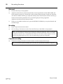
Avoid excessive heat, humidity, dust, and vibration.
Keep the MT4X away from locations where it is likely to be
exposed to high temperatures or humidity, such as direct
sunlight, near radiators, stoves, etc. Also avoid locations which
are subject to excessive dust accumulation or vibration which
could cause mechanical damage.
2
Avoid physical shocks
Strong physical shocks can cause damage. Handle the unit with
care.
3
Clean with a soft dry cloth
Never use solvents such as benzine or thinner to clean the
MT4X. Wipe it clean with a soft dry cloth.
4
Do not open the case or attempt repairs or modification
yourself
The MT4X contains no user-serviceable parts. For other than
routine cleaning, refer all maintenance to qualified YAMAHA
service personnel. Opening the case and/or tampering with the
internal circuitry will void the warranty.
5
Make sure power is off before making or removing
connections
Always turn the power OFF prior to connecting or
disconnecting cables. This will prevent damage to the MT4X as
well as other connected equipment.
6
Handle cables carefully
Always plug and unplug cables — including the AC cord — by
gripping the connector, not the cord.
7
Always use the correct power supply
The MT4X is sold configured to the appropriate power
specifications for the local area. The power supply voltage and
power consumption are listed on the bottom panel. If you move
to an area with a different AC mains voltage, be sure to check
with your nearest YAMAHA dealer before using the unit.
8
Keep the heads and tape path clean
To ensure consistent high performance and sound quality from
the MT4X, it is important to clean the heads and tape path
regularly — ideally before each recording session. Use a
cleaning kit specifically designed to use with cassette tape
equipment.
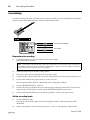
9
Use only high-quality chrome cassette tape
The MT4X is designed to be used with Chrome tape (CrO2 tape
— Bias: HIGH or TYPEII position; EQ: 70µs). It will not work
properly with Ferrichrome tape formulations. You may
experience high frequency distortion if you use such tapes.
The use of tapes longer than 90 minutes (C-120 and longer) is
not recommended. These tapes are much thinner and therefore
prone to poor performance or failure.
TDK SA 46 – 90 and Maxell XLII 46 – 90 are recommended.
10 Handle the cassette tapes properly
You should fast forward and rewind new tapes before you
record on them. This will prevent any possible binding that
could be caused by the tape being tightly wound at the factory.
It is best not to use the first and last 20 seconds of a tape. The
splice between the leader and the tape can cause distortion.
When loading a cassette, check that the tape is not loose, then
load the tape firmly into the cassette compartment. If the tape is
not loaded properly, the unit may jam or otherwise malfunction.
11 Use the dbx™ switch correctly
To obtain the best possible sound quality, you should always use
the dbx™ noise reduction system to playback tapes that were
recorded with the dbx™ system on. If the tape was recorded
without dbx™, turn the noise reduction system off.
The dbx™ noise reduction system was manufactured based on a
patent licence from THAT Corporation. dbx is a trademark of
Carillion Electronics Corporation.
Contents
Precautions1
Introduction2
Features2
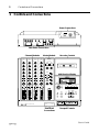
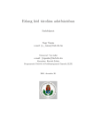
Structure of the MT4X3
1 Controls and Connections5
Channel Modules6
Master Module7
Recorder Controls8
Transport Controls10
Multi-function Display10
Front Panel Connections11
Rear Panel Connections12
Power Connections13
2 Example System14
3 Recording Functions15
Monitoring15
Initial recording16
Overdubbing19
Punch-in/out recording21
Ping-pong recording29
Mixdown32
4 Synchronization34
FSK recording35
Synchronized playback36
Synchronized mixdown39
5 Memory Functions41
Memo Function41
Repeat Function42
Recording Levels Function42
Appendix44
Troubleshooting44
Maintenance45
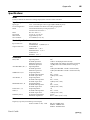
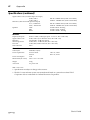
Specifications46
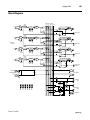
Block Diagram48
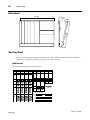
Dimensions49
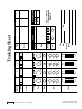
Tracking Sheet49
Glossary51
User’s Guide
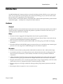
Introduction
2
Introduction
Your MT4X Multitrack Cassette recorder is a powerful recording tool that will allow you to capture your
music at a very high level of sound quality. It is an advanced technology, easy-to-use four-track cassette
tape recorder with a comprehensive four-channel mixer.
In order to make use of the many features of the MT4X and to obtain the best performance, please read this
manual thoroughly — and keep it in a safe place for future reference.
Features
General
The MT4X consists of a four-channel mixer section and a four-track cassette tape recorder section inside a
compact enclosure. Independent recording and playback is possible for each track. This allows you to
create high-quality multi-track recordings.
Mixer
• The mixer section is equipped with independent stereo buses for greater flexibility.
• Continuously variable gain controls are provided for each input channel. These can be used with any
input source, from microphones to electronic instruments.
• Each channel has a three band equalizer (HIGH, MID, and LOW) giving you flexible tone-shaping
capabilities.
• Dual AUX SEND and AUX RETURN (stereo) connectors allow you to add effects from external signal
processors. You can assign the AUX RETURN signal to each channel as required.
Recorder
• The dbx noise reduction system provides substantial noise reduction and a wide dynamic range.
• An automatic punch-in/out recording function and a rehearsal function make recording easier and
more accurate. Locate functions, such as memory and return-to-zero are provided for additional
convenience.
• A large, multi-functional display shows the recording and playback levels, along with a tape counter
and other indicators, giving you immediate and helpful information about the status of the MT4X.
• The pitch control allows you to vary the tape speed with in a range of approximately ±10%. This can be
useful when you have to compensate for pitch variations during an overdub.
• The tape transport is a full-logic mechanism, making recording and playback operation smooth and
simple.
• The transport offers two speeds: 9.5 cm/sec and 4.8 cm/sec.
User’s Guide
3
4
10
9
8
7
6
5
4
3
2
1
0
6
5
4
3
2
1
0
6
5
4
3
2
1
0
0
7
MAX
0
0
0
2
4
10
1
10
10
10
10
CUE LEVEL
8
MIN
4
3
2
1
0
ASSIGN
2
9
PHONES
CUE
STEREO
GROUP
3
10
MONITOR
SELECT
0
3
1
LEVEL
4
2
AUX RETURN
ASSIGN
1
MASTER
L/MONO
AUX RETURN
MONITOR/PHONES
2
1
3
1
2
10
L
7
R
8
AUX SEND
1
9
MIC/
LINE
2
10
R
EVEN
4
TAPE
C
L
ODD
PAN
3
2
ASSIGN
AUX 2
1
+12
AUX 1
0
-12
LOW
+12
+12
0
-12
MID
-12
AUX
0
MIC
MIC/LINE
LINE
HIGH
GAIN
MIC/LINE INPUT
MONITOR OUT
L/MONO
R
L
STEREO OUT
1
SYNC/4
2
2
REC SELECT
3
TAPE OUT
3
1
4
3
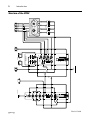
Introduction
Structure of the MT4X
User’s Guide
Introduction
4
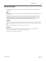
Structure of the MT4X
The MT4X can be divided into three basic sections – the mixer, the recorder, and the bus lines which
connect them:
Mixer
The mixer has four input channels. It adjusts the input signals at each respective channel and sends them
to the bus lines.
The signals input to each channel of the mixer can be switched to either input signals (MIC/LINE) or
playback signals (TAPE). When TAPE is selected, the playback signal from each track is input to the
corresponding channel. The tone of the signal is adjusted through the equalizer and the volume at the
channel faders. It is then sent to the bus lines using the ASSIGN keys and PAN control.
Bus Lines
There are four main bus lines (group buses) which receive the input signals from each respective channel
of the mixer. If signals from two or more input channels are sent to a bus line, these signals are overlaid or
mixed.
There is also a STEREO bus (L, R), an AUX bus (1, 2), and a CUE bus.
Recorder
The signals from the bus lines are recorded by the cassette recorder. It also sends the signal to the
TAPE OUT connectors and back to the mixer (including the CUE bus).
Also refer to the "Block Diagram" on page 48.
User’s Guide
Controls and Connections
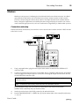
Power Connections
POWER
ON
OFF
R
R
L/MONO
2
L/MONO
2
SYNC/4
1
3
2
1
1
R
L
R
AUX RETURN
MONITOR OUT
AUX SEND
L
4
TAPE OUT
3
2
STEREO OUT
1
MIC/LINE INPUT
1
Controls and Connections
AC IN
5
Rear Panel Connections
Master Module
Channel Modules
1
2
MIC/LINE
3
4
MIC/LINE
MIC/LINE
GAIN
GAIN
MASTER
MIC/LINE
GAIN
GAIN
AUX RETURN
1
2
1
LINE
HIGH
0
MIC
LINE
HIGH
0
MIC
LINE
HIGH
0
Recorder Controls
MIC
LINE
HIGH
0
MIC
2
1
ASSIGN
3
2
ASSIGN
4
3
4
LEVEL
-12
MID
0
-12
LOW
0
+12
-12
MID
0
+12
-12
LOW
0
+12
-12
MID
0
+12
-12
LOW
0
+12
-12
MID
0
+12
-12
LOW
0
+12
0
10
+12
-12
AUX
+12
-12
AUX
+12
10
CUE LEVEL
MONITOR
SELECT
-12
AUX
0
+12
-12
AUX
1
Multi-function Display
+12
1
3
GROUP
2
AUX 1
AUX 2
AUX 1
AUX 2
AUX 1
AUX 2
AUX 1
AUX 2
1
2
1
2
1
2
1
2
0
10
0
10
2
4
STEREO
TAPE
3
ASSIGN
3
ASSIGN
4
3
ASSIGN
4
3
ASSIGN
4
3
CUE
9.5 4.8
4
1
AUTO PUNCH
C
C
PAN
C
PAN
MEMO
C
PAN
0
MONITOR/PHONES
PAN
10
SYNC
START
IN
OUT
REPEAT
2
4
R
EVEN
L
ODD
R
EVEN
L
ODD
R
EVEN
L
ODD
R
EVEN
TAPE
MIC/
LINE
TAPE
MIC/
LINE
TAPE
MIC/
LINE
TAPE
MIC/
LINE
MIN
MAX
0
10
1
2
3
2
3
TRACK
4
L
4
R
STEREO
REC SELECT
TAPE SPEED CONTROL
PITCH
4.8 / 9.5
1
O
10
10
10
10
10
10
9
9
9
9
9
9
8
8
8
8
8
8
7
7
7
7
7
7
6
6
6
6
6
6
5
5
5
5
5
5
4
4
4
4
4
4
3
3
3
3
3
3
2
2
2
2
2
2
1
1
1
1
1
1
0
0
0
0
0
0
AUTO
PUNCH I/O
SYNC
REHE
MULTITRACK CASSETTE RECORDER
REC
1
NOISE REDUCTION SYSTEM
L
ODD
+9
6
3
0
3
6
10
-20
+9
6
3
0
3
6
10
-20
PHONES
CHECK
CLEAR
REC/PAUSE
PLAY
2
3
REPEAT
RETURN
TO ZERO
MEMO 1
LOCATE
MEMO 2
LOCATE
REW
FF
4
COUNTER
RESET
STOP
PUNCH I/O
Front Panel
Connections
Transport Controls
User’s Guide
Controls and Connections
6
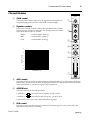
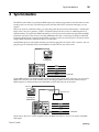
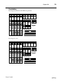
Channel Modules
1
MIC/LINE
1
GAIN control
GAIN
This rotary control adjusts the level of the signal from a microphone or
instrument plugged into the MIC/LINE INPUT connector (h).
2
1
LINE
HIGH
0
-12
MID
0
-12
LOW
0
-12
AUX
0
MIC
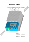
Equalizer controls
These rotary controls are used to adjust the high, middle and low band
frequency levels. To help you select the “flat” setting easily, each control
has a centre-detent at the “0” position.
HIGH
±12 dB at 12kHz - shelving
MID
±12 dB at 1kHz - peaking
LOW
±12 dB at 80Hz - shelving
2
+12
+12
3
AUX 1
AUX 2
1
2
4
ASSIGN
3
15
4
C
PAN
5
10
RESPONSE (dB)
+12
5
6
L
ODD
R
EVEN
TAPE
MIC/
LINE
0
–5
10
9
8
–10
7
6
–15
5
20
50
100 200
500
1k
2k
5k
10k
20k
4
3
FREQUENCY (Hz)
2
7
3
1
0
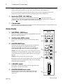
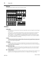
AUX controls
This rotary control is used to send the channel signal after the fader (7) to the auxiliary send buses.
Rotated fully counter-clockwise sends the signal to the AUX 1 bus, fully clockwise to the AUX 2 bus.
In the centre-detent “0” position, no signal is sent to either bus.
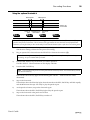
4
ASSIGN keys
These keys are used to select the group bus.
1-ASSIGN-2
1
2
selects the first track group - groups 1 and 2.
3-ASSIGN-4
3
4
selects the second track group - groups 3 and 4.
Use the PAN control (5) to select the individual track groups.
5
PAN control
This rotary control sets the stereo pan position of the channel signal. It is also used to select the
individual track groups for recording.
User’s Guide
7
Controls and Connections
ODD/L: Rotated fully counter-clockwise sends the signal to the odd (1 or 3) numbered track of the
selected track group (ASSIGN keys 4) and to the left channel of the STEREO bus.
EVEN/R: Rotated fully clockwise sends the signal to the even (2 or 4) numbered track of the
selected track group (ASSIGN keys) and to the right channel of the STEREO bus.
6
Input select (TAPE - MIC/LINE) key
This key selects the input source for the channel. Pressed in ( ), it selects the tape track
corresponding to the channel module (for example, the channel 1 key selects track 1). In the out
position ( ), the source is the MIC/LINE INPUT connector (h).
7
Channel fader
This linear control is used to set the channel level. For optimal performance and signal balance, the
fader should be positioned between 7 and 8.
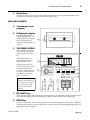
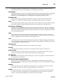
Master Module
8
MASTER
AUX RETURN - ASSIGN keys
These keys assign the signal from the AUX RETURN connectors
(i) to the selected group bus.
9
AUX RETURN
1
8
2
4
1
0
10
1
3
0
10
0
10
MONITOR/PHONES 0
4
10
GROUP
2
2
4
3
A
CUE
B
MIN
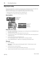
CUE LEVEL controls
MONITOR/PHONES level control
This rotary control adjusts the volume level of the stereo
PHONES (d) connector and the MONITOR OUT (f)
connectors.
0
STEREO
These rotary controls adjust the level of the signal from each
track before it is sent to the cue bus.
B
4
CUE LEVEL
CUE: This key selects the cue bus signals. These are the playback
signals direct from the cassette tracks. When you are recording,
the record signal is monitored.
A
10
MONITOR
SELECT
GROUP: These keys select groups 1 and 3 and groups 2 and 4
respectively. If you select both keys, groups 1 and 3 will be sent
to the left channel and groups 2 and 4 will be sent to the right
channel.
STEREO: This key selects the stereo bus signal.
3
9
MONITOR SELECT keys
These keys are used to select the group buses, the stereo bus,
and the cue bus signals. The signals are routed to the
MONITOR OUT (f) connectors on the rear panel and the
stereo PHONES (d) connector on the front of the MT4X.
2
ASSIGN
LEVEL
0
0
1
ASSIGN
3
Auxiliary return LEVEL controls
These rotary controls adjust the level of the auxiliary return
signal.
2
1
C
MAX
10
9
8
7
6
5
4
3
2
1
0
0
10
10
9
8
7
6
5
4
3
2
1
0
User’s Guide
Controls and Connections
C
8
Master fader
This linear control is used to set the level of the master stereo bus. For optimal performance and
signal balance, the fader should be positioned between 7 and 8.
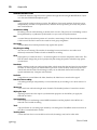
Recorder Controls
D
Cassette tape compartment
E
Multi-function display
This FLD (Fluorescent
Light Display) shows the
operating modes and signal
levels of the MT4X. See
"Multi-function Display" on
page 10.
F
D
TAPE SPEED CONTROL
These controls consist of a
rotary PITCH control and a
tape speed (4.8/9.5) select
key.
The PITCH control can
adjust the tape speed by
approximately ±10%.
The tape speed (4.8/9.5)
select key is used to switch
the tape speed between
9.5 cm/sec and 4.8 cm/sec.
9.5 cm/sec will be selected
automatically when the
power is turned on.
Note: The tape speed
cannot be changed while the
tape transport is in motion.
Press the STOP key (W),
then press the tape speed
select key.
G
TAPE
9.5 4.8
E
1
AUTO PUNCH
MEMO
SYNC
START
IN
OUT
REPEAT
2
+9
6
3
0
3
6
10
-20
+9
6
3
0
3
6
10
-20
REC
1
1
NOISE REDUCTION SYSTEM
2
3
2
3
TRACK
4
L
4
R
STEREO
REC SELECT
TAPE SPEED CONTROL
PITCH
F
G
4.8 / 9.5
1
O
AUTO
PUNCH I/O
SYNC
JK L
CHECK
CLEAR
M
N
2
3
REPEAT
RETURN
TO ZERO
MEMO 1
LOCATE
MEMO 2
LOCATE
O
P
4
H
I
COUNTER
RESET
Q
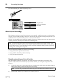
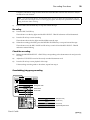
REC SELECT keys
These keys are used to arm the tracks for recording. When you press a REC SELECT key, the record
select indicator (c) for the corresponding track flashes on the multi-function display (E).
H
REPEAT key
This key is used to start and cancel the repeat function. When the repeat function is active, the MT4X
will repeatedly playback a selection between two memory points set with the MEMO keys (O). See
"Repeat Function" on page 42.
User’s Guide
9
Controls and Connections
When the automatic punch-in/out function is active, the REPEAT key causes the MT4X to
immediately start the rehearsal mode. See "Using the automatic punch-in/out function" on page 21.
Note: The repeat interval must be more than three counts on the tape counter (Y).
I
RETURN TO ZERO key
This key rewinds the tape to the point where the tape counter (Y) reads “0000”. The tape counter
flashes while the tape rewinds.
J
dbx key
This key is used to turn the dbx‘ noise reduction system on and off. By default, the dbx™ system is
turned on when the MT4X is first powered on.
The dbx™ system has no effect on track 4 when the SYNC key (K) is on. See "FSK recording" on
page 35.
K
SYNC key
This key defeats the dbx™ noise reduction system on track 4. This allows you to record FSK signals
onto the track. See "FSK recording" on page 35.
L
CLEAR key
This key clears the stored memory points. When automatic punch-in/out is active (the
AUTO PUNCH indicator ^ is illuminated), this key clears the current setting (but does not clear
the memory points).
M
AUTO PUNCH I/O key
This key is used to start and cancel the automatic punch-in/out function. See "Using the automatic
punch-in/out function" on page 21.
N
CHECK key
This key is used to verify the memory points. Press and hold this key and the press one of the
MEMO keys (O). The corresponding MEMO indicator (a) will flash and the stored value will be
shown on the tape counter (Y).
O
MEMO (1, 2) keys
These keys store the current tape counter (Y) value as memory points. When you press one of these
keys, the corresponding MEMO indicator (a) will light and the point stored.
You can clear the memory points by pressing the CLEAR key (L), removing the cassette tape, or
turning off the power.
P
LOCATE (1, 2) keys
These keys locate to the stored memory points. When you press one of these keys, the MT4X will
fast forward or rewind to the corresponding memory point.
Note: The locate interval must be more than three counts on the tape counter (Y).
Q
COUNTER RESET key
This key resets the tape counter (Y) to “0000”.
User’s Guide
Controls and Connections
10
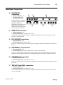
Transport Controls
R
REHE key and indicator
This key is used to perform a recording
rehearsal. While the LED indicator over the key
is illuminated, you can simulate a recording
session. This allows you to check recording
levels or practice punch-in/out without actually
recording.
S
REHE
REC/PAUSE
PLAY
R
S
T
REW
FF
U V
STOP
W
REC/PAUSE key and indicator
This key is used to record. Before you can actually record, you must arm the tracks with the
REC SELECT keys (G). Press this key to place the MT4X in record standby mode. Once you press
the PLAY key (T), recording will begin.
Press the key again to pause the recording.
T
PLAY key and indicator
U
REW key
This key is used to rewind the cassette tape.
V
FF key
This key is used to fast forward the cassette tape.
W
STOP key
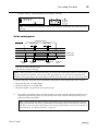
Multi-function Display
This section details the indicators of the FLD (Fluorescent Light Display) multi-function display
(E).
Y
X
Z
TAPE
[
\
9.5 4.8
MEMO
SYNC
]
X
1
AUTO PUNCH
START
IN
^
OUT
REPEAT
2
a
REC
b
+9
6
3
0
3
6
10
-20
+9
6
3
0
3
6
10
-20
1
2
3
4
L
R
c
TAPE indicator
This indicator illuminates when a cassette tape is inserted in the cassette tape compartment. If you
press any of the transport keys before you have inserted a tape, the indicator will flash.
User’s Guide
11
Controls and Connections
Y
Tape counter
This indicator displays tape position.
Z
Level meters
These indicators display the signal level within a range of -20 dB to +9 dB. The individual tracks and
the stereo bus are displayed.
• When dbx™ is off, the normal signal limit is approximately 0 dB.
• When dbx™ is on, the normal signal limit is approximately +6 dB.
Note: The meters can be switched to peak hold. To switch peak hold on or off, press the
COUNTER RESET key (Q) while holding down the STOP key (W).
[
Tape speed indicator
These indicators show the current tape speed selection, either 9.5 cm/sec or 4.8 cm/sec. When the
MT4X is first powered on, it defaults to 9.5 cm/sec.
\
dbx indicator
This indicator illuminates when the dbx™ noise reduction system is turned on.
]
SYNC indicator
This indicator illuminates when SYNC key (K) has been switched on.
^
AUTO PUNCH indicators
These indicators show the status of the automatic punch-in/out function. See "Using the automatic
punch-in/out function" on page 21.
a
MEMO indicators
These indicators illuminate when their respective memory points have been set.
b
REPEAT indicator
This indicator illuminates while the repeat function is active.
c
REC SELECT - TRACK indicators
These indicators flash when you arm the corresponding track by pressing one of the REC SELECT
keys (G). The armed indicators switch from flashing to illuminated when you press the REC/
PAUSE key (S).
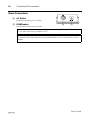
Front Panel Connections
d
PHONES connector
PHONES
PUNCH I/O
d
e
This 1/4” phone connector is used for a pair of stereo headphones
(8 Ω to 40 Ω).
e
PUNCH I/O footswitch connector
This connector is used to plug in an optional footswitch (FC5) for
punch-in/out recording. See "Using the optional footswitch" on
page 28.
User’s Guide
Controls and Connections
12
Rear Panel Connections
f
MONITOR OUT
connections
• Output impedance: 1 kΩ
• Nominal output level:
-10 dB (at 10 kΩ load)
These RCA/Phono connectors
are used to plug in a monitor
amplifier or powered
loudspeakers. The same signal
which is output from the
PHONES connector (d) is also
output from these connectors.
g
f
g
h
MONITOR OUT
STEREO OUT
MIC/LINE INPUT
R
L
R
AUX RETURN
3
2
AUX SEND
2
R
4
L
1
TAPE OUT
1
L/MONO
R
i
L/MONO
2
1
j
SYNC/4
3
2
1
k
STEREO OUT connections
• Output impedance: 1 kΩ
• Nominal output level: -10 dB (at 10 kΩ load)
These RCA/Phono connectors are used to output the final stereo mixdown to the master recorder —
typically, a stereo tape deck.
h
MIC/LINE INPUT connections
• Input impedance: 10 kΩ
• Nominal input level: -10 dB to -50 dB
These 1/4” phone connectors are used to input microphones, electronic instruments, and line-level
sources.
i
AUX RETURN (1, 2) connections
• Input impedance: 10 kΩ
• Nominal input level: -10 dB (AUX RETURN - LEVEL control nominal)
These 1/4” phone connectors are used to input the signals from external effects devices and other
signal processors. If the external device is monaural, plug it into one of the L/MONO connectors.
j
AUX SEND (1, 2) connections
• Output impedance: 1 kΩ
• Nominal output level: -10 dB (at 10 kΩ load)
These 1/4” phone connectors are used to output signals to external effects devices and other signal
processors.
k
TAPE OUT (1 to 4/SYNC) connections
• Output impedance: 1 kΩ
• Nominal output level: -10 dB (at 10 kΩ load)
These RCA/Phono connectors are used to output the individual tracks directly from the recorder
section of the MT4X.
User’s Guide
13
Controls and Connections
Power Connections
l
AC IN inlet
Connect the supplied power cord here.
m
POWER switch
AC IN
l
POWER
ON
OFF
m
This switch turns the power on and off.
Note: Always make sure the Master fader (C) is set to “0” and the MONITOR/PHONES level control
is set to “MIN” when turning the MT4X on or off.
CAUTION (FOR CANADIAN MODEL)
TO PREVENT ELECTRIC SHOCK, MATCH WIDE BLADE OF PLUG TO WIDE SLOT, FULLY
INSERT.
User’s Guide
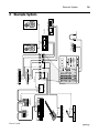
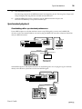
Compressor
Microphone
Bass Effect Processor
Bassguitar
Synthesizer
MIDI Converter
1
1
MIDI
OUT
2
TAPE OUT
FSK Signal
2
3
MIDI IN
SYNC/4
MIC/LINE INPUT
1
Rhythm
Programmer
3
AUX SEND
Delay Processor
2
Sequencer
4
L/MONO
MIDI IN
1
MIDI IN
L
STEREO OUT
R
MIDI OUT
L
R
AUX RETURN
L/MONO
User’s Guide
MONITOR OUT
2
Multi-effect Signal Processor
NS-10M STUDIO
FC5 Footswitch
Headphones
Master Recorder
Amplifier
2
R
R
MIDI
OUT
Example System
Example System
14
NS-10M STUDIO
15
Recording Functions
3
Recording Functions
The basic functions of multitrack recording are as follows:
Monitoring
Monitoring the recording or playback to listen for mistakes or
unwanted distortion.
Initial recording
Overdub recording
Recording the first instrument or part.
Punch-in/out recording
Ping-pong recording
Mixdown
Correct mistakes or add short segments to an existing track.
Recording additional instruments or parts while monitoring the
previously recorded tracks.
Bounce several existing tracks onto another track.
Mix the results of your multitrack recording onto a stereo master
tape.
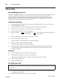
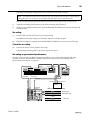
Monitoring
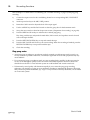
The MT4X offers you a great deal of flexibility in monitoring the status of your recordings. You can
monitor the individual channel groups, the stereo bus, the cue bus, or any combination.
You control monitoring with the MONITOR SELECT keys 0:
GROUP
STEREO
CUE
The GROUP keys allow you to monitor the group bus signals. If you only
press one key, you will hear monaural output. If you press both keys, you will
hear groups 1 and 3 in the left channel and groups 2 and 4 in the right channel.
The signals on the group buses go directly to the recorder.
The STEREO key allows you to monitor the stereo bus signal. You can monitor
the signals from the four input channels as well as the AUX RETURN signal.
Some of these signals may not have been assigned to the group bus, allowing
you to listen to signals that will not be recorded.
The CUE key allows you to monitor the playback signals directly from the
cassette tracks. You can set the volume for each track with the CUE LEVEL
controls. The cue bus is monaural.
When you are recording, the record signal is monitored.
MONITOR
SELECT
1
3
GROUP
2
4
STEREO
CUE
MONITOR/PHONES
MIN
MAX
Of these three monitor sources, you will probably find the cue bus is the most useful. This bus allows you
to monitor the previously recorded tracks as well as new material independently of the mixer section. It is
sometimes very important to be able to listen directly to the tracks, for example, to compare different
mixer settings to the original signal.
You adjust the overall monitoring level with the MONITOR/PHONES control.
User’s Guide
Recording Functions
16
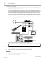
Initial recording
The first step in multitrack recording is to record the initial tracks. Usually, these are your rhythm tracks:
bassguitar, rhythm guitar, and drums.
Note: Before you record anything, you must connect the MT4X to both an input source and a monitoring
system. See "Example System" on page 14.
d
ban
on
a
poep e
l
Track 1
Track 2
Track 3
Track to be recorded
Track 4
Preparations for recording
1)
Insert a cassette tape into the cassette tape compartment (D).
2)
Connect the input source to the corresponding MIC/LINE INPUT connector for each channel.
3)
Set the input select key (6) to the MIC/LINE position.
4)
Rotate the GAIN control (1) to adjust the initial level of the input signal.
If you have plugged a microphone into the corresponding connector, rotate the control fully
clockwise to the MIC setting.
If you have plugged a synthesizer into the connector, or are running a bassguitar or guitar through a
signal processor (line level output), rotate the control fully counter-clockwise to the LINE setting.
Note: This level setting is temporary — just to get a rough signal level based on the type of input you have
connected. Be aware that you could easily be sending a signal that is overloading the gain amplifier and
causing distortion. To set the final level, see steps 10 and 11.
User’s Guide
17
Recording Functions
5)
Using the ASSIGN keys (4) and the PAN control (5) select the group bus you want the input
signal to go to.
Press the
ASSIGN key:
Press the
ASSIGN key:
Press the
ASSIGN key:
Press the
ASSIGN key:
1
2
1
2
3
4
3
4
Group 1
→
Track 1
Group 2
→
Track 2
Group 3
→
Track 3
Group 4
→
Track 4
and rotate the
PAN control:
The input signal is sent to the first (odd) group.
and rotate the
PAN control:
The input signal is sent to the second (even)
group.
and rotate the
PAN control:
The input signal is sent to the third (odd)
group.
and rotate the
PAN control:
The input signal is sent to the fourth (even)
group.
If the PAN control is set to a position partway between L/ODD and R/EVEN, the input signal will
be sent to both the odd and even group buses.
If you press both ASSIGN keys, the input signal will be sent to at least two group buses.
6)
Press the REC SELECT keys (G) for the tracks you want to record.
REC SELECT
1
2
3
4
The corresponding REC SELECT - TRACK indicator (c) on the display will flash.
Press the REC SELECT key again to cancel the selection.
7)
Press the MONITOR SELECT - CUE key (0). Adjust the CUE LEVEL controls (A) for the selected
tracks. Set the monitor volume with the MONITOR/PHONES level control (B).
Tip: You can ignore step 7 and use any monitor mode or combination that you are comfortable with. See
"Monitoring" on page 15.
8)
Press the COUNTER RESET key (Q) to set the tape counter (Y) to “0000”.
Set the recording levels
In order to obtain the best possible sound quality, it is very important to set optimal recording levels. If
you set the levels too low, you will be able to notice tape noise. If you set the levels too high, the tape will
be saturated and distortion will result. Therefore, you should set the recording levels to the highest level
before distortion sets in.
The MT4X is equipped with sensitive peak-hold level meters (Z). You can monitor the level of the
individual tracks and the stereo bus. Use the level meters in conjunction with the monitoring modes (see
"Monitoring" on page 15) to set your recording levels.
User’s Guide
Recording Functions
18
Note: The meters display a range of -20 dB to +9 dB. If the meters exceed the normal limit momentarily, this is
usually perfectly acceptable. Cassette tape is reasonably forgiving of transients – and human hearing has difficulty
detecting the minor distortion that results. Where you start getting audible problems is when the meters are
constantly above the normal limit. You must lower the levels in order to maintain decent sound quality.
9)
Press the REC/PAUSE key (S).
The indicator above the key lights and any flashing REC SELECT - TRACK indicators will be
illuminated.
10)
Set the channel fader (7) to the nominal level between “7” and “8”.
11)
Adjust the GAIN control while watching the level meters.
• When dbx™ is off, adjust the gain control so that the +3 dB segment occasionally illuminates.
• When dbx™ is on, adjust the gain control so that the +9 dB segment occasionally illuminates.
Note: The MT4X can recall and display the maximum recording levels obtained during a session. See
"Recording Levels Function" on page 42.
Record the track
12)
Press the PLAY key (T).
The indicator above the key lights and the MT4X starts the tape. Start playing.
Tip: If your song starts with drums, bassguitar, and guitars all on the first bar, you will need to record a
count-in.
13)
When the track is complete, press the RETURN TO ZERO key (I) to stop and rewind the tape.
Tip: You may want to use the STOP key (W) to stop the tape and mark a memory point. See "Memory
Functions" on page 41.
The indicators above the REC/PAUSE and PLAY keys switch off and the REC SELECT - TRACK
indicators resume flashing.
Check the completed recording
Once the tape has rewound back to “0000” on the tape counter, you should check the recording.
14)
Press the PLAY key to playback the tape.
15)
If the recording needs to be redone, repeat the previous steps.
16)
• If the problem with the recording was a musical error, press the REC/PAUSE key and repeat
steps 12 to 14.
• If the problem was due to incorrect recording levels or other engineering problems, adjust the
parameters by repeating steps 4 to 14.
When you are finished with an instrument, you should set the channel fader to “0”. You may even
want to disconnect the input source.
User’s Guide
19
Recording Functions
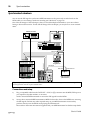
Overdubbing
Overdub recording is the basis of all multi-track recording. It enables you to record additional instruments
or parts track-by-track while listening to the previously recorded tracks.
Track 1
Track to be overdubbed
Track 2
Track 3
Drum track
Track 4
Preparations for recording
1)
Connect the input source for each channel to the corresponding
MIC/LINE INPUT connector.
Note: Connecting an instrument with a high output impedance such as an electric guitar or bassguitar
to the MT4X may increase noise and distortion. If this happens, connect a direct box or effect unit between
the instrument and the MT4X to reduce the impedance.
2)
Set the input select key to the MIC/LINE position.
3)
Rotate the GAIN control to adjust the level of the input signal.
4)
Using the ASSIGN keys and the PAN control select the group bus you want the input signal to go to.
5)
Press the REC SELECT keys for the tracks you want to record.
The corresponding REC SELECT - TRACK indicator on the display will flash.
6)
Press the MONITOR SELECT - CUE key.
7)
Press the PLAY key to playback the tape. As the tape plays, adjust the CUE LEVEL controls for the
selected tracks. Set the monitor volume with the MONITOR/PHONES level control.
8)
Press the RETURN TO ZERO key to rewind the tape back to “0000” on the tape counter.
Set the recording levels
9)
Press the REHE key (R).
The indicator above the key lights and any flashing REC SELECT - TRACK indicators will be
illuminated.
10)
Set the channel fader to the nominal level between “7” and “8” and adjust the GAIN controls.
User’s Guide
Recording Functions
20
Rehearsal
After you have set the recording levels, you should rehearse the overdub to verify and adjust the settings
and cue levels.
11)
Press the PLAY key to start the rehearsal.
The indicator above the key lights and the MT4X starts the tape. Start playing.
Tip: Sometimes the pitch of an instrument and the pitch of the previously recorded tracks is slightly
different. If you cannot adjust the pitch of the instrument, you can compensate for the error with the TAPE
SPEED CONTROL (F) - PITCH control. The PITCH control can adjust the tape speed by approximately
±10%. During rehearsal, adjust the PITCH control until you have matched the instrument with the tracks.
12)
Press the RETURN TO ZERO key to stop the rehearsal and rewind the tape.
The indicators above the REHE and PLAY keys switch off and the REC SELECT - TRACK indicators
resume flashing.
Record the track
13)
Press the REC/PAUSE key.
The indicator above the key lights and any flashing REC SELECT - TRACK indicators will be
illuminated.
14)
Press the PLAY key.
The indicator above the key lights and the MT4X starts the tape. Play the part again.
Note: To prevent wow and flutter effects, do not accidentally adjust the PITCH control while you are
recording.
15)
When the track is complete, press the RETURN TO ZERO key to stop and rewind the tape.
The indicators above the REC/PAUSE and PLAY keys switch off and the REC SELECT - TRACK
indicators resume flashing.
Check the completed recording
16)
Press the PLAY key to playback the tape and check the recording.
17)
If the recording needs to be redone, repeat the previous steps.
User’s Guide
21
Recording Functions
To overdub another part, simply repeat steps 1 to 17.
Track 1
Bassguitar track
Track 2
Track to be overdubbed
Track 3
Drum track
Track 4
Punch-in/out recording
This technique is used to re-record short sections, correct mistakes, or add new sections to silent passages.
You play your part while punching in and out to start and stop the recorder. For the greatest precision, you
should use the advanced automatic punch-in/out features of the MT4X.
However, it is reasonably easy to punch-in manually. If you have a footswitch, you can also punch in and
out using your foot. This keeps your hands free for making music.
Tip: You should ensure that the mixer and instrument settings are identical to the original recording. If you
record a punch-in at a different volume level, for example, it will not blend into the previously-recorded track and
your edit will be obvious. You will find keeping accurate track sheets invaluable to making invisible punch-in/out
recordings. See "Tracking Sheet" on page 49.
There are three basic methods for punch-in/out recording:
• Using the automatic punch-in/out function.
• Using the REC/PAUSE key and the PLAY key.
• Using the optional footswitch.
Using the automatic punch-in/out function
With the automatic punch-in/out function, you specify the punch-in and punch-out locations. The
operation is then carried out automatically. If you make a mistake, you can repeat the operation with
precision.
1)
Connect the input source, set the input select key, and adjust the GAIN control and channel fader so
that the mixer setting is identical to the previous recording.
Note: If you are using an optional FC5 footswitch, plug it into the PUNCH I/O footswitch connector.
2)
Press the REC SELECT key for the track you want to punch-in.
User’s Guide
Recording Functions
22
The REC SELECT - TRACK indicator on the display will flash.
+9
6
3
0
3
6
10
-20
+9
6
3
0
3
6
10
-20
TAPE
9.5
1
2
3
4
REHE
L
REC/PAUSE
PLAY
R
Note: You can skip step 2 at this point. However, you must select a track before you perform the actual
recording.
Set the working points:
Automatic rewind
AUTO PUNCH
Blank space
Blank space
Track to be
re-recorded
START
Pre-roll
point
IN
Punch-in
point
Segment to be
re-recorded
*
Punch-out
point
OUT
Post-roll
point
* Post-roll is 10 counts on the tape counter
at 9.5 cm/sec (5 counts at 4.8 cm/sec).
Note: When you perform a punch-in/out recording, you need to find a blank section of about 1 second for your
punch-in and punch-out locations. This is because of the gap between the erase head and record/playback head.
Otherwise you may find that you have accidentally erased material that was before or after the re-recorded segment.
• The pre-roll point - the punch-in/out operation starts playback at this point to give you a count-in.
• The punch-in point - recording begins.
• The punch-out point - recording ends.
• The post-roll point - the punch-in/out operation stops.
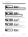
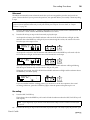
3)
Fast-wind or rewind the tape to the location where you want to start the pre-roll. A location two or
three measures before the punch-in point usually works well. Press the AUTO PUNCH I/O key
(M) to mark the pre-roll point.
Note: If you press this key while a memory point is stored (either or both memory indicators a on the
display are illuminated), the memory point data will be temporarily deleted and the indicator(s) switched
off. When you cancel the Auto Punch function, the memory point data will be restored and the indicator(s)
illuminated again. See "Memory Functions" on page 41.
User’s Guide
23
Recording Functions
The AUTO PUNCH and START indicators (^) on the display and the indicator above the REHE
key will begin flashing.
TAPE
9.5
AUTO PUNCH
+9
6
3
0
3
6
10
-20
+9
6
3
0
3
6
10
-20
START
1
2
3
4
REHE
L
REC/PAUSE
PLAY
R
Note: The AUTO PUNCH indicator will either be flashing or illuminated while the automatic punch-in/
out function is active.
4)
Press the PLAY key (or step on the footswitch) to play the tape.
The START indicator will light and the IN indicator will begin flashing. The indicator above the
REC/PAUSE key will flash rapidly.
TAPE
9.5
AUTO PUNCH
START
+9
6
3
0
3
6
10
-20
+9
6
3
0
3
6
10
-20
IN
1
2
3
4
REHE
L
REC/PAUSE
PLAY
R
Note: You can reverse the order of steps 3 and 4. In this case, you would mark the start
point while playing by pressing the AUTO PUNCH I/O key.
5)
At the punch-in location, press the REC/PAUSE key (or step on the footswitch).
The START indicator will switch off, the IN indicator will light, the OUT indicator will begin
flashing, and the punch-in point will be stored. The indicator above the PLAY key will flash rapidly.
TAPE
9.5
AUTO PUNCH
IN
6)
+9
6
3
0
3
6
10
-20
+9
6
3
0
3
6
10
-20
OUT
1
2
3
4
REHE
L
REC/PAUSE
PLAY
R
At the punch-out location, press the PLAY key (or step on the footswitch).
The IN indicator will switch off, the OUT indicator will light, and punch-out point will be stored.
TAPE
9.5
AUTO PUNCH
+9
6
3
0
3
6
10
-20
+9
6
3
0
3
6
10
-20
OUT
1
2
3
4
REHE
L
REC/PAUSE
PLAY
R
Ten (10) counts on the tape counter (at 9.5 cm/sec - 5 counts at 4.8 cm/sec) after the punch-out
location becomes the post-roll point. The OUT indicator will switch off, the START indicator will
begin flashing, and the tape is automatically rewound back to the pre-roll point.
When tape is rewound, the AUTO PUNCH and START indicators will light and the indicator above
the REHE key will flash rapidly.
TAPE
9.5
AUTO PUNCH
START
+9
6
3
0
3
6
10
-20
+9
6
3
0
3
6
10
-20
1
2
3
4
REHE
L
REC/PAUSE
PLAY
R
User’s Guide
Recording Functions
24
Rehearsal
The MT4X automatically enters rehearsal mode after you have assigned the punch-in and punch-out
points. This mode allows you to practice the punch-in/out operation before you actually commit anything
to tape.
Note: In this mode, you can press the REPEAT key (H) to start Repeat Rehearsal. The MT4X will automatically
perform rehearsal playback between the pre-roll point and the post-roll point. For more detail, see "Repeat
Function" on page 42.)
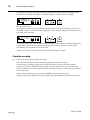
7)
Press the MONITOR SELECT - CUE key. Adjust the CUE LEVEL controls for the selected tracks. Set
the monitor volume with the MONITOR/PHONES level control.
8)
Press the PLAY key (or step on the footswitch) to play the tape.
At the punch-in location, the START indicator will switch off, the IN indicator will light, and the
indicator above the REHE key will light. If you are monitoring the cue bus, the sound will switch
from the tape to the input source.
TAPE
9.5
AUTO PUNCH
+9
6
3
0
3
6
10
-20
+9
6
3
0
3
6
10
-20
IN
1
2
3
4
REHE
L
REC/PAUSE
PLAY
R
At the punch-out location, the IN indicator and indicator above the REHE key will switch off, the
OUT indicator will light, and monitor source will switch back to the tape.
TAPE
9.5
AUTO PUNCH
+9
6
3
0
3
6
10
-20
+9
6
3
0
3
6
10
-20
OUT
1
2
3
4
REHE
L
REC/PAUSE
PLAY
R
At the post-roll point, the OUT indicator will switch off, the START indicator will begin flashing,
and the tape is automatically rewound back to the pre-roll point.
When tape is rewound, the AUTO PUNCH and START indicators will light and the indicator above
the REHE key will flash rapidly.
TAPE
9.5
AUTO PUNCH
START
+9
6
3
0
3
6
10
-20
+9
6
3
0
3
6
10
-20
1
2
3
4
REHE
L
REC/PAUSE
PLAY
R
If you are satisfied with the working points, you can move on to the next operation, the actual
recording. Otherwise, press the CLEAR key (L) to clear the points and repeat steps 3 to 6.
Recording
9)
Press the REC/PAUSE key.
The indicator above the REHE key will switch off and the indicator above the REC/PAUSE key will
flash rapidly.
Note: If you skipped step 2, you need to use the REC SELECT key(s) to select a track (or tracks) before
you record.
10)
Press the PLAY key (or step on the footswitch) to play the tape. Get ready to play the punch-in part.
User’s Guide
25
Recording Functions
At the punch-in location, the START indicator will switch off, the IN indicator will light, and the
indicator above the REC/PAUSE key and the REC SELECT - TRACK indicator will light.
TAPE
9.5
AUTO PUNCH
+9
6
3
0
3
6
10
-20
+9
6
3
0
3
6
10
-20
IN
1
2
3
4
REHE
L
REC/PAUSE
PLAY
R
Play the punch-in part.
At the punch-out location, the IN indicator and indicator above the REC/PAUSE key will switch
off, the REC SELECT - TRACK indicator will flash, the OUT indicator will light, and monitor source
will switch back to the tape.
TAPE
9.5
AUTO PUNCH
+9
6
3
0
3
6
10
-20
+9
6
3
0
3
6
10
-20
OUT
1
2
3
4
REHE
L
REC/PAUSE
PLAY
R
At the post-roll point, the OUT indicator will switch off, the START indicator will begin flashing, the
indicator above the PLAY key will flash in a pattern (check waiting condition), and the tape is
automatically rewound back to the pre-roll point.
When tape is rewound, the AUTO PUNCH and START indicators will light.
Check the recording
11)
Press the PLAY key again to play back the tape.
The MT4X will automatically play from the pre-roll point to the post-roll point.
If the resulting recording is good, press the AUTO PUNCH I/O key to cancel the automatic
punch-in/out function. The punch-in and punch-out points as well as the pre-roll and post-roll
points are cleared. If you want to perform another automatic punch-in/out recording, you will have
to start from step 3.
If the resulting recording is not good, press the REHE key and repeat from step 7.
If the pre-roll or post-roll points need to be changed, press the CLEAR key and repeat from step 3.
User’s Guide
Recording Functions
26
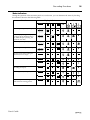
Status indicators
During the operation of the automatic punch-in/out function, you can determine the status by checking
the indicators shown in the following table:
Function
Display Indicators
AUTO PUNCH
START
IN
LEDs
OUT
2
REHE
REC/PAUSE
PLAY
Mark the pre-roll point (see step 3).
AUTO PUNCH
2
START
(slowly)
Start the tape playing (see step 4). If
you press the AUTO PUNCH I/O
key while the tape is playing, the
operation starts here.
AUTO PUNCH
START
2
IN
(slowly)
(rapidly)
Mark the punch-in point (see step 5).
IN
AUTO PUNCH
OUT
2
(slowly)
Mark the punch-out point (see step 6).
(rapidly)
OUT
2
AUTO PUNCH
(slowly)
The tape is rewound, waiting for
rehearsal (also see step 6).
Rehearsal mode (see step 8).
AUTO PUNCH
START
2
(rapidly)
AUTO PUNCH
2
IN
AUTO PUNCH
OUT
2
The tape is rewound, ready for
recording (see step 9).
Recording mode (see step 10).
AUTO PUNCH
START
2
(rapidly)
AUTO PUNCH
2
IN
AUTO PUNCH
OUT
2
While the tape is rewinding, the Play
LED flashes the waiting pattern.
User’s Guide
AUTO PUNCH
START
2
(waiting)
(oo—oo—)
27
Recording Functions
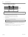
Using the REC/PAUSE key and the PLAY key
Blank space
Blank space
Track to be
re-recorded
Punch-in
point
PLAY
REC/PAUSE
Segment to be
re-recorded
Punch-out
point
PLAY
STOP
Note: When you perform a punch-in/out recording, you need to find a blank section of about 1 second for your
punch-in and punch-out locations. This is because of the gap between the erase head and record/playback head.
Otherwise you may find that you have accidentally erased material that was before or after the re-recorded segment.
1)
Connect the input source, set the input select key, and adjust the GAIN control and channel fader so
that the mixer setting is identical to the previous recording.
2)
Press the REC SELECT key for the track you want to punch-in.
The REC SELECT - TRACK indicator on the display will flash.
3)
Press the PLAY key.
The indicator above the key lights and the MT4X starts the tape. Get ready to play the punch-in part.
4)
At the punch-in location, press the REC/PAUSE key.
Note: You can practice the punch-in at this point with the rehearsal function. Press the REHE key instead
of the REC/PAUSE key.
The indicator above the key lights and the flashing REC SELECT - TRACK indicator will be
illuminated. Play the punch-in part.
5)
Press the PLAY key at the punch-out location.
The indicator above the REC/PAUSE key switches off and the REC SELECT - TRACK indicator
resumes flashing.
You could also use the STOP key or the RETURN TO ZERO key at this point.
User’s Guide
Recording Functions
28
Using the optional footswitch
Blank space
Blank space
Track to be
re-recorded
Punch-in
point
Play
Segment to be
re-recorded
Record
Punch-out
point
Play
Stop
Note: When you perform a punch-in/out recording, you need to find a blank section of about 1 second for your
punch-in and punch-out locations. This is because of the gap between the erase head and record/playback head.
Otherwise you may find that you have accidentally erased material that was before or after the re-recorded segment.
1)
Connect the input source, set the input select key, and adjust the GAIN control and channel fader so
that the mixer setting is identical to the previous recording.
2)
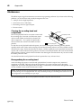
Plug an optional FC5 footswitch into the PUNCH I/O footswitch connector (e).
Note: Yamaha supplies an optional footswitch, FC5. Using another manufacturer’s footswitch may cause
mis-timing. See your Yamaha dealer for details.
3)
Press the REC SELECT key for the track you want to punch-in.
The REC SELECT - TRACK indicator on the display will flash.
4)
Press the REC/PAUSE key.
Note: You can practice the punch-in at this point with the rehearsal function. Press the REHE key instead
of the REC/PAUSE key.
The indicator above the key lights and the flashing REC SELECT - TRACK indicator will be
illuminated.
5)
Step on the footswitch.
The indicator above the PLAY key lights, the indicator above the REC/PAUSE key will flash rapidly,
and the MT4X starts the tape. Get ready to play the punch-in part.
6)
At the punch-in location, step on the footswitch again.
The indicator above the REC/PAUSE key lights. Play the punch-in part.
7)
Step on the footswitch at the punch-out location.
The indicator above the REC/PAUSE key switches off.
User’s Guide
29
Recording Functions
Ping-pong recording
Ping-pong recording allows you to bounce several previously-recorded tracks onto an unrecorded track.
Using this technique, you can create a recording with effectively more than four tracks.
There are two basic techniques you can employ when making a bounce-down recording:
• Mixing three previously-recorded tracks onto a destination track.
• Overdubbing a new sound source during a ping-pong recording.
Bouncing tracks
Bassguitar track
Guitar track
b
Drum track
an
d
n
o
poep l
a
Track 1
(Bassguitar track)
Track 2
(Guitar track)
Track 3
(Drum track)
Track 4
Rhythm track
e
Preparation for recording
1)
Fast-wind or rewind the tape to the beginning of your recording. Press the COUNTER RESET key to
set the tape counter to “0000”.
2)
Set the input select keys to the TAPE position for the source tracks.
3)
On each of the source tracks, use the ASSIGN keys and the PAN control to select the group bus for
the destination track.
4)
Press the REC SELECT key for the destination track.
The corresponding REC SELECT - TRACK indicator on the display will flash.
5)
Press the MONITOR SELECT - GROUP key corresponding to the destination track.
Rehearsal
6)
Press the REHE key.
The indicator over the key lights and the flashing REC SELECT - TRACK indicators will be
illuminated.
7)
Press the PLAY key to start the rehearsal.
The indicator above the key lights and the MT4X starts the tape.
8)
Adjust the channel fader, PAN controls, and equalizer controls for each source channel.
User’s Guide
Recording Functions
30
If required, add effects using the AUX SEND and AUX RETURN controls and connectors. Adjust
the effects for each channel.
Note: You cannot apply effects to the individual tracks nor can you adjust the sound balance once you
have mixed them onto a single track. You must apply any effects, and adjust the equalization and balance,
during the bounce-down recording.
9)
Press the RETURN TO ZERO key to stop and rewind the tape.
Recording
10)
Press the REC/PAUSE key.
The indicator over the key lights and the REC SELECT - TRACK indicators will be illuminated.
11)
Press the PLAY key to start recording.
The indicator above the key lights and the MT4X starts the tape.
12)
When the recording is finished, press the RETURN TO ZERO key to stop and rewind the tape.
The indicators over the REC/PAUSE and PLAY keys switch off and the REC SELECT - TRACK
indicators resume flashing.
Check the recording
13)
Release the MONITOR SELECT - GROUP key corresponding to the destination track and press the
CUE key.
14)
Adjust the CUE LEVEL control of the newly-recorded destination track.
15)
Press the PLAY key to start playback of the tape.
If the resulting recording needs to be redone, repeat from step 6.
Overdubbing/ping-pong recording
Bassguitar track
Guitar track
b
Drum track
an
d
n
o
poep l
a
e
User’s Guide
Track 1
(Bassguitar track)
Track 2
(Guitar track)
Track 3
(Drum track)
Track 4
Synth & Rhythm track
31
Recording Functions
This technique is a combination of overdubbing (see "Overdub recording" on page 15) and ping-pong
recording.
1)
Connect the input source for the overdubbing channel to its corresponding MIC/LINE INPUT
connector.
2)
Set the input select key to the MIC/LINE position.
3)
Rotate the GAIN control to adjust the level of the input signal.
4)
Use the ASSIGN keys and the PAN control to select the group bus for the destination track.
5)
Set up the source tracks as listed in the previous section ("Preparation for recording" on page 29).
6)
Press the REHE and PLAY keys to rehearse the overdub/ping-pong.
Play along with the tape. Adjust the channel fader, PAN controls, and equalizer controls for each
source and input channel.
7)
Press the RETURN TO ZERO key to stop and rewind the tape.
8)
Press the REC/PAUSE and PLAY keys to start recording. When the recording is finished, press the
RETURN TO ZERO key to stop and rewind the tape.
9)
Check the recording.
Ping-pong notes
• Avoid ping-pong recordings to an adjacent track (for example, avoid bouncing track 2 to track 1 or
track 3) as much as possible. Otherwise, crosstalk (the signal leak at the record/playback head) may
cause feedback.
• If you must ping-pong to an adjacent track, set your recording levels carefully. Set the tape speed to
9.5 cm/sec for the highest quality sound. Do not boost the HIGH equalizer control too much. You
should also use the dbx™ noise reduction system to avoid feedback and control noise levels.
• Unfortunately, sound quality will deteriorate rapidly if you overuse the ping-pong recording
technique. You should try to plan out your multitrack recording to minimize the amount of bouncing
that you need to perform. Remember, Sgt. Pepper’s Lonely Hearts Club Band by the Beatles, was recorded
on a four-track system!
User’s Guide
Recording Functions
32
Mixdown
Mixdown is the process of combining the four individual tracks into a final stereo mix. You blend
and polish the sounds before you record them onto a stereo cassette recorder or DAT recorder.
The mix is created using the various mixer controls. You adjust the track levels with the channel
faders, change the equalizations, and modify the stereo image with the pan controls. You can also
connect external signal processors, such as a reverberator or digital delay, to further refine your mix.
Connections and setup
In these instructions, the MT4X is your multitrack recorder and the stereo cassette recorder or DAT recorder
is the master recorder.
Master Recorder
DAT
Multi-effect Signal Processor
L
STEREO OUT
AUX RETURN - 2
AUX RETURN - 1
AUX SEND - 2
AUX SEND - 1
Delay Processor
R
1)
Using compatible cables, plug the stereo inputs of the master recorder into the STEREO OUT
connectors (g).
2)
Connect any external signal processors to the MT4X. Plug a compatible cable from the AUX SEND
connector (j) into the input connector on the effect unit. Plug the output from the effect unit into
the AUX RETURN connectors (i).
Note: If the effect unit has stereo outputs, connect it to the MT4X in stereo. Otherwise, plug it into the
L/MONO connector.
Note: The MT4X has two auxiliary (AUX SEND and AUX RETURN) channels.
For an alternative setup, you can connect an external effects unit in between the MT4X
(STEREO OUT connectors) and your master recorder.
3)
Set the input select keys to the TAPE position for the individual tracks.
4)
Press the MONITOR SELECT - STEREO key 0. Set the master fader to the nominal level between
“7” and “8”.
User’s Guide
33
Recording Functions
Rehearsal
5)
Press the PLAY key to start playback.
6)
Adjust the channel levels with the channel faders. Set the equalization with the HIGH, MID, and
LOW equalizer controls (2). Use the Pan control to adjust the pan position. Set the aux send level
with the AUX SEND controls (3). Adjust the auxiliary return levels with the LEVEL controls (9).
Set the levels and other parameters of any connected signal processing equipment.
Adjust the record levels on the master recorder.
7)
When you are satisfied with the levels, press the RETURN TO ZERO key to stop the rehearsal and
rewind the tape.
Recording
8)
Insert a tape into the master recorder.
9)
Start recording on the master recorder. Press the PLAY key on the MT4X to start playback.
Note: You may want to remove any count-ins before you create your master tape. There are several ways
of doing this. One method is to switch (input select key) the track that contains the count-in to the MIC/
LINE position until the count is completed and then switch it to the TAPE. Another method is to set the
MT4X to start playback after the count-in. Use the method that you find most comfortable.
Check the recording
10)
When the recording is finished, rewind the master recorder and play back the tape.
Tip: You can add a synchronized MIDI part to your mix. See "Synchronized mixdown" on page 39.
User’s Guide
Synchronization
4
34
Synchronization
The MT4X has the ability to synchronize MIDI sequencers, rhythm programmers, and other devices to the
existing tracks on your tape. The following section describes some of the advanced techniques you can
employ.
When you create an overdub recording, you play along with the previously recorded tracks – matching the
tempo. This is easy for a guitarist, vocalist, or keyboard player, but not so easy for a MIDI sequencer or
rhythm machine. To synchronize MIDI instruments, you need to provide a timecode signal that the MIDI
instrument can follow. This involves recording MIDI timecode onto a track using a technique called FSK
(Frequency Shift Keying). Typically, the best time to do this is when you are laying down your basic tracks
using a MIDI sequencer or rhythm machine to set the tempo.
Some MIDI sequencers and rhythm machines are already equipped with a SYNC OUT connector. You can
plug this type of machine directly into the MT4X to record FSK onto one of the tracks.
FSK Signal
Rhythm
Programmer
Track 1
Track 2
Track 3
FSK track
Track 4
If your MIDI sequencer or rhythm machine is not equipped with a SYNC OUT connector, you may need a
MIDI/FSK converter such as the Yamaha YMC10. You plug the MIDI/FSK converter in between your
MIDI sequencer or rhythm machine and the MT4X to record FSK onto one of the tracks.
MIDI OUT
FSK Signal
Rhythm
Programmer
(MIDI Master)
MIDI IN
TAPE SYNC OUT
MIDI Converter
Track 1
Track 2
Track 3
Track 4
FSK track
Please refer to the user’s manual supplied with your MIDI instrument to see if it can output compatible
FSK signals.
User’s Guide
35
Synchronization
FSK recording
Record FSK signals on track 4
The MT4X is equipped with a dbx™ noise reduction system. For recording normal audio signals, the noise
reduction system is beneficial. However, dbx™ interferes with the recording of FSK signals. This
sometimes results in an unusable sync track. Therefore, the MT4X is also equipped with a SYNC key.
When you press the SYNC key, the dbx™ system is defeated on track 4, allowing you to have noise
reduction on your audio tracks and a usable sync track.
Connections and setup
1)
Connect the MIDI/FSK output from your sequencer, rhythm machine, or converter to one of the
MIC/LINE INPUT connectors.
2)
Set the input select key for the corresponding channel to the MIC/LINE position.
3)
Rotate the GAIN control fully counter-clockwise to the LINE setting.
4)
Set the equalizer controls to the “0” (flat) position.
5)
Press the ASSIGN
key:
6)
Set the channel fader to the nominal level between “7” and “8”.
7)
Press the REC SELECT key for track 4.
3
4
and rotate the
PAN control:
fully clockwise to select the fourth (even)
group - track 4.
The REC SELECT - TRACK indicator on the display will flash.
8)
If dbx™ system is on, press the SYNC key (K).
The SYNC indicator (]) on the display will light.
9)
If you are going to record audio signals from the MIDI instrument along with the FSK signal,
connect the audio outputs to the channel connectors and set the mixer channels. See "Initial
recording" on page 15.
Rehearsal
10)
Press the REHE key to put the MT4X into rehearsal mode.
11)
Start the MIDI instrument and adjust the recording levels.
Adjust the level of the FSK signals so that the level meters indicate about +6 dB.
12)
Adjust the monitoring levels.
13)
Stop the MIDI instrument.
Record the sync track
Note: These instructions assume you have recorded a song on your MIDI sequencer or rhythm machine that
consists of a song start, tempo, and a song end. If you programmed tempo changes, these will also be recorded on
the FSK track.
14)
Fast-wind or rewind the tape to the beginning of your recording. Press the COUNTER RESET key to
set the tape counter to “0000”.
15)
Press the REC/PAUSE and PLAY keys to start recording.
User’s Guide
Synchronization
16)
36
Start the MIDI instrument.
Run the song program on the MIDI instrument from beginning to end. The Song Start, Tempo (and
tempo changes), and Song End are recorded onto the FSK track.
17)
When the MIDI program has completed, stop the MIDI instrument and press the
RETURN TO ZERO key to stop and rewind the tape.
Synchronized playback
Overdubbing with a synchronized performance
If your MIDI sequencer or rhythm machine cannot accept FSK signals, you may need a MIDI/FSK
converter such as the Yamaha YMC10. You need to plug the MIDI/FSK converter in between the MT4X
and your MIDI instrument.
MIDI IN
MIDI OUT
MIDI IN
MIDI IN
Sequencer
Rhythm
Programmer
Synthesizer
FSK Signal
TAPE OUT
SYNC/4
MIDI OUT
TAPE SYNC IN
MIDI Converter
(MIDI Master)
Some MIDI sequencers and rhythm machines can read FSK signals. You can plug this type of machine
directly to the MT4X to synchronize to the recorded FSK signal.
MIDI IN
MIDI OUT
MIDI IN
Sequencer
Synthesizer
MIDI OUT
FSK Signal
TAPE OUT
SYNC/4
Rhythm
Programmer
User’s Guide
37
Synchronization
Connections and setup
1)
Plug a compatible cable from the TAPE OUT - SYNC/4 (k) connector into the MIDI/FSK input on
your sequencer, rhythm machine, or converter.
Set the connected MIDI instrument to FSK sync mode, to receive the FSK signals from the MT4X. Set
any other connected MIDI instruments to MIDI clock mode to slave to the MIDI device receiving the
FSK signals. Perform any other required setup on your MIDI instruments to ensure they perform
correctly once the MT4X starts playing the FSK signals.
Please refer to the instruction manual supplied with your MIDI instrument for further setup details.
2)
Connect your MIDI instrument(s) to a monitor mixer. Then connect the input source for each
channel to the corresponding MIC/LINE INPUT connector.
MIDI IN
Monitor signal
Synthesizer
MIDI OUT
MIDI IN
Sequencer
MIDI OUT
MIDI IN
Rhythm
Programmer
TAPE SYNC IN
MIDI OUT
Monitor Mixer
FSK Signal
MIC/LINE
1
MIDI Converter
(MIDI Master)
TAPE OUT
SYNC/4
Track 1
Overdub track
Track 2
Track 3
Track 4
FSK track
Adjust the input and monitor levels. See "Overdubbing" on page 19.
Tip: You may find it easier to have just one monitor channel to adjust. Plug a cable between the
MONITOR OUT connectors and the input channels of the monitor mixer.
3)
Press the REC SELECT keys for the tracks you want to record.
The corresponding REC SELECT - TRACK indicator on the display will flash.
4)
If dbx™ system is on, press the SYNC key. The SYNC indicator will light.
Rehearsal
5)
Press the REHE key to put the MT4X into rehearsal mode.
6)
Press the PLAY key to start playback.
User’s Guide
Synchronization
38
The MIDI instrument(s) will playback in sync with the data recorded on track 4.
Note: If the MIDI instrument does not play correctly, you probably started the tape at a point after the
FSK signal began. You must ensure the tape plays back from before the start of the FSK track.
Play the overdub part along with the MIDI instrument(s) and the previously recorded tracks.
7)
Adjust the recording and monitoring levels while watching the level meters.
8)
When you are satisfied with the levels, press the RETURN TO ZERO key to stop the rehearsal and
rewind the tape.
Recording
9)
Press the REC/PAUSE and PLAY keys to start recording.
The MIDI instrument(s) will play automatically. Play the overdub part again.
10)
When the recording is complete, press the RETURN TO ZERO key to stop and rewind the tape.
Check the recording
11)
Press the PLAY key to start playback of the tape.
If the resulting recording needs to be redone, repeat from step 5.
Recording a synchronized performance
You may want to record your MIDI instrument(s) while they are synchronized with the FSK signal
recorded on track 4. The procedure is similar to the previous section (see "Overdubbing with a
synchronized performance" on page 36).
MIDI IN
MIDI OUT
MIDI IN
MIDI IN
Sequencer
Rhythm
Programmer
Synthesizer
Audio Signal
Audio Signal
MIC/LINE INPUT
FSK Signal
MIDI OUT
1 2
TAPE OUT
SYNC/4
TAPE SYNC IN
MIDI Converter (MIDI Master)
Track 1
Rhythm track
Track 2
Synthesizer track
Track 3
Track 4
User’s Guide
FSK track
39
Synchronization
Synchronized mixdown
You can use the FSK signal to synchronize MIDI instruments to the previously recorded tracks on the
MT4X while you are creating a mixdown recording (see "Mixdown" on page 32).
One of the advantages of this technique is that you can add multiple instruments to your mix without
having to bounce-down tracks. To take full advantage of this technique, you may have to use an external
mixer.
Master Recorder
MIDI OUT
DAT
MIDI IN
Sequencer
MIDI IN
Synthesizer
MIDI OUT
MIDI IN
R
TAPE OUT
L
Mixing Console
Rhythm
Programmer
FSK Signal
1 2 3 SYNC/4
MIDI OUT
TAPE SYNC IN
MIDI Converter
(MIDI Master)
Tip: A special feature of the MT4X is its TAPE OUT connectors. These allow you to send the track signals
directly from the recorder to your external mixer.
Connections and setup
1)
Plug a compatible cable from the TAPE OUT - SYNC/4 (k) connector into the MIDI/FSK input on
your sequencer, rhythm machine, or converter.
Set the connected MIDI instrument to receive the FSK signals from the MT4X.
2)
Set any other connected MIDI instruments to MIDI clock mode to slave to the MIDI device receiving
the FSK signals. Perform any other required setup on your MIDI instruments to ensure they
perform correctly once the MT4X starts playing the FSK timecode.
Please refer to the instruction manual supplied with your MIDI instrument for further setup details.
User’s Guide
Synchronization
3)
40
Plug compatible cables from the other TAPE OUT connectors (1, 2, and 3) into the inputs of your
mixer.
Tip: An alternative approach is to create a stereo mixdown with the built-in mixer and send that to the
external mixer from the STEREO OUT connectors.
4)
Connect the audio outputs from the MIDI instruments to the mixer inputs.
5)
Connect the stereo inputs of the master recorder to the stereo outputs of the mixer.
6)
Connect any external signal processors to the auxiliary connectors of the mixer.
Rehearsal
7)
If dbx™ system is on, press the SYNC key. The SYNC indicator will light.
8)
Press the PLAY key to start playback.
The MIDI instruments will start to playback in sync with the data recorded on track 4.
9)
Adjust the levels, equalization, and pan of each channel on the mixer. Set the auxiliary send and
return.
Adjust the record levels on the master recorder.
10)
When you are satisfied with the levels, press the RETURN TO ZERO key to stop the rehearsal and
rewind the tape.
Recording
11)
Insert a tape into the master recorder.
12)
Start recording on the master recorder. Press the PLAY key on the MT4X to start playback.
The synchronized mixdown will be carried out automatically.
Check the recording
13)
When the recording is finished, rewind the master recorder and play back the tape.
User’s Guide
41
Memory Functions
5
Memory Functions
Memo Function
Store a memory location
You can mark two memory locations which can be used to quickly return to a specific point on your tape.
1)
Fast-wind or rewind the tape to the location you want stored.
For example, you can locate the end of a track just by stopping the tape.
2)
Press the MEMO-1 or MEMO-2 key (O).
The corresponding MEMO indicator (a) will flash three times and then light.
TAPE
9.5
1
MEMO
+9
6
3
0
3
6
10
-20
+9
6
3
0
3
6
10
-20
1
2
3
4
L
R
Check the memory locations
1)
Press and hold the CHECK key (N).
2)
Press the appropriate MEMO key.
The tape counter (Y) will display the corresponding memory point value. The number portion of
the MEMO indicator will flash for as long as the two keys are pressed.
The following display shows the MEMO-2 location being checked.
TAPE
9.5
1
MEMO
+9
6
3
0
3
6
10
-20
+9
6
3
0
3
6
10
-20
2
1
2
3
4
L
R
Locate to a stored location
1)
Press the appropriate LOCATE key (P).
The MT4X will fast-wind or rewind the tape to the stored location. While the tape is in motion, the
number portion of the MEMO indicator will flash.
The following display shows the results of pressing the LOCATE-2 key.
TAPE
9.5
1
MEMO
2
+9
6
3
0
3
6
10
-20
+9
6
3
0
3
6
10
-20
1
2
3
4
L
R
Note: The locate interval must be more than three counts on the tape counter.
If you reset the tape counter, the MT4X will re-calculate the stored memory locations. When you
check a memory location, the value displayed will reflect the reset tape counter. When you locate to
a memory location, the MT4X will fast-wind or rewind to the correct location.
User’s Guide
Memory Functions
42
Repeat Function
The MT4X will repeatedly play a section of the tape between two memory locations.
1)
Press the REPEAT key (H).
The MT4X will fast-wind or rewind the tape to the first memory location. While the tape transport is
in fast-wind or rewind mode, the REPEAT indicator (b) will flash on the display.
TAPE
9.5
1
MEMO
REPEAT
2
2)
+9
6
3
0
3
6
10
-20
+9
6
3
0
3
6
10
-20
1
2
3
4
L
R
As soon as the MT4X has reached the first memory location, playback is started.
The REPEAT indicator is illuminated.
Repeat notes
• If only one memory location is stored, the MT4X will repeat from the tape counter location “0000” to
the stored point.
• Playback is repeated 16 times continuously, then the tape is rewound back to the first memory location
and stopped. The REPEAT indicator is switched off.
• You cannot change the memory locations during repeat playback.
• The repeat interval must be more than three counts on the tape counter.
Recording Levels Function
The MT4X will store the maximum recording level for all four tracks and the stereo signal. The
location of the highest level is also stored and can be displayed along with the level.
If the signal is beyond the recommended level, the maximum level segment will flash.
dbx™ ON
≥ +10 dB
dbx™ OFF
≥ +6 dB
Confirm the maximum level
1)
Press and hold the CHECK key.
2)
Press the REHE key (R).
The maximum level segment of the level meters (Z) will light for as long as the two keys are
pressed. If the level is beyond the recommended level, the segment will flash.
TAPE
9.5
+9
6
3
0
3
6
10
-20
+9
6
3
0
3
6
10
-20
1
2
3
4
L
Confirm the tape position
1)
Press and hold the CHECK key.
User’s Guide
R
43
Memory Functions
2)
Press the REC SELECT key (G) corresponding to the track you want to check.
The maximum level segment of the selected track will light and the tape counter will display the
corresponding location value for as long as the two keys are pressed. If the level is beyond the
recommended level, the segment will flash.
The following display shows Track 2 being checked.
TAPE
9.5
+9
6
3
0
3
6
10
-20
+9
6
3
0
3
6
10
-20
1
2
3
4
REC SELECT
L
R
1
2
3
4
Note: If the maximum level is reached a several locations, only the first location is
displayed.
If you reset the tape counter after the recording, the location displayed will be incorrect. Unlike the
memo function, the MT4X does not re-calculate the maximum level memory locations.
Clear the maximum level data
1)
Press and hold the STOP key (W).
2)
Press the CLEAR key (L).
When the data is cleared, the -20 dB segments on the level meters for all four tracks and the stereo
signal will flash three times.
TAPE
9.5
+9
6
3
0
3
6
10
-20
+9
6
3
0
3
6
10
-20
1
2
3
4
L
R
Note: The maximum recording level data is NOT cleared automatically. Before each
recording, you should reset the stored levels. Otherwise you could mistake the levels of a
previous recording for the current recording.
User’s Guide
Appendix
44
Appendix
Troubleshooting
If you experience difficulty operating the MT4X, or it does not seem to be working as it should, look up the
problem in the following table. You may find it is just a simple error, easy to correct.
Symptom
Possible Cause
Solution
The MT4X cannot be
powered ON.
The power cable is not correctly
connected.
Make sure the power cable is connected to a suitable
AC outlet and plugged into the AC IN connector on
the MT4X’s rear panel.
The POWER switch has not been
correctly set.
Make sure the POWER switch on MT4X’s rear panel
is pressed ON.
Note: If the MT4X still cannot be powered ON, please contact your Yamaha dealer.
Cannot record.
The REC SELECT key is not set
correctly.
Set the REC SELECT key correctly.
The setting of the ASSIGN key(s)
is incorrect.
Select the correct ASSIGN key(s) for the group and
tracks you intend to use.
The cassette is loaded incorrectly. Make sure the tape is firmly inserted in the cassette
compartment.
The cassette’s record protect tabs
have been removed.
Make sure that the cassette’s record protect tabs are
intact.
The corresponding input select
key is set incorrectly.
Set the input select key to the correct position.
The fader or monitor is set
incorrectly.
Raise the fader for the input module. Make sure the
MONITOR SELECT switch is set to CUE and adjust
the CUE LEVEL control.
Recordings sound noisy or
distorted.
The recording level is set
incorrectly.
Set the channel fader so that the level occasionally
reaches +9 dB (with dbx™ ON or +3 dB with it
OFF). If the signal level is too low, the recording
may sound noisy. If it is too high, distortion may
occur.
Recordings sound dull,
suffer from wow and
flutter, or are of poor
quality.
The record/playback head and
capstan is dirty.
Clean the record/playback head and mechanism.
See "Maintenance" on page 45.
The wrong type of cassette is
being used.
Be sure to use high-quality Type II (High Bias, 70 µs
EQ) chrome cassettes.
Cannot hear a connected
instrument.
Recordings playback at
the wrong pitch.
Tape sync does not
function correctly.
User’s Guide
The cassette tape is defective.
Try a new cassette tape.
The PITCH control was reset
during recording.
Set the PITCH control to the “0” centre-detent
position.
The tape speed was reset.
Press the tape speed select key to set the MT4X back
to the correct tape speed.
The SYNC key was not pressed
when the dbx™ system was ON.
Press the SYNC key and connect the FSK source to
track 4.
The FSK track was recorded at too
low a level.
Re-record the FSK signal. Make sure the recording
level is set to about +3dB.
The MIDI-to-FSK converter is
incorrectly connected.
Make sure the connections are correct.
45
Appendix
Maintenance
The MT4X requires regular maintenance to remain in top operating condition. If you observe the following
problems, you should clean and possibly demagnetize the unit:
• A drop in level at high frequencies.
• An increase in wow and flutter.
• Fluctuating sound or signal dropout.
• Excessive noise.
Cleaning the recording head and
components
The record/playback head is in constant contact with
the recording tape. Over time it will become coated
with an oxide residue and need to be cleaned. The
other components — the capstan and pinchroller —
also tend to become coated with residue and dust
particles.
Pinchroller
Record/playback head
Capstan
Erase head
Clean the Shaded Areas
To clean the record/playback head and capstan, use a head-cleaning kit. These kits generally include
specially-made cotton swabs and an isopropyl alcohol-based cleaning solution, and are available at audio
and electronics shops. Follow the directions on the kit, carefully wiping the record/playback head and the
capstan with a swab soaked in cleaning solution. It is best to clean the pinchroller with a non-alcohol based
rubber cleaning solution, which is often included in the cleaning kits. Alcohol tends to dry out and corrode
the rubber part of the roller.
You should clean the record/playback head and capstan after every 10 hours of use.
Demagnetizing the recording head
As the recording tape passes over the record/playback head, it tends to impart a tiny amount of
magnetism to the head. The head collects this magnetism over a period of time, slowly becoming
magnetized. You need to demagnetize the head using a commercially-available head demagnetizer. These
are also available at most audio and electronics shops.
Note: Read the directions on the demagnetizer carefully. If you do not use the demagnetizer correctly, you could
seriously damage the record/playback head. Also, keep recorded tapes away from the demagnetizer when it is in use;
the demagnetizer can accidentally erase your tapes.
You should demagnetize the record/playback head after every 20 to 30 hours of use.
User’s Guide
Appendix
46
Specifications
Model
4-track/4-channel one direction recording and playback cassette recorder with mixer
Tape Transport
Tape Type
Track Configuration
Heads
Motor
Tape Speed
Pitch Control
Wow & Flutter
C-46 ~ 90 cassette tapes CrO2 - Type II (Bias: HIGH; EQ 70 µs)
4-track/4-channel one direction recording and playback
4-track Hard Permalloy record/play head × 1
4-track ferrite erase head × 1
DC servo motor × 1
9.5 cm/sec , 4.8 cm/sec
Approximately ±10%
0.1% WRMS (9.5 cm/sec)
Electrical Specifications
Input connectors
Output connectors
MIC/LINE × 4
AUX RETURN L/MONO, R × 2
AUX SEND × 2
STEREO OUT L, R × 1
MONITOR OUT L, R × 1
TAPE OUT × 4
PHONES L, R × 1
Connectors
MIC/LINE
AUX RETURN L/R 1, 2
STEREO OUT L, R
AUX SEND 1, 2
MONITOR OUT L, R
TAPE OUT 1, 2, 3,
SYNC/4
PHONES (stereo)
Input impedance
Nominal input level
Minimum input level
Maximum input level
Input impedance
Nominal input level
Minimum input level
Output impedance
Nominal load impedance
Nominal output level
Output impedance
Nominal load impedance
Nominal output level
Output impedance
Nominal load impedance
Nominal output level
Output impedance
Nominal load impedance
Nominal output level
Nominal load impedance
Maximum output level
10 kΩ
-10 dB to -50 dB (input fader nominal)
-56 dB (GAIN control MAX, input fader maximum)
+10 dB (GAIN control MIN, headroom margin)
10 kΩ
-10 dB (AUX RETURN - LEVEL control nominal)
-16 dB (AUX RETURN - LEVEL control maximum)
1 kΩ
10 kΩ or more
-10 dB (at 10 kΩ load)
1 kΩ
10 kΩ or more
-10 dB (at 10 kΩ load)
1 kΩ
10 kΩ or more
-10 dB (at 10 kΩ load)
1 kΩ
10 kΩ or more
-10 dB (at 10 kΩ load)
8 to 40 Ω
45mw + 45mw (at 40 Ω load)
Mixer
Frequency response (at nominal input and output)
20 Hz to 20 kHz +1 dB / -3 dB
User’s Guide
MIC IN - STEREO OUT
LINE IN - STEREO OUT
LINE IN - PHONES OUT
47
Appendix
Specifications (continued)
Signal-to-Noise ratio (at nominal input and output)
68 dB / IHF-A
75 dB / IHF-A
Distortion (1 kHz at nominal input and output)
0.1% / 30 kHz LPF
0.03% / 30 kHz LPF
Equalizer
LOW
MID
HIGH
MIC IN - STEREO OUT (GAIN control MAX)
LINE IN - STEREO OUT (GAIN control MIN)
MIC IN - STEREO OUT (GAIN control MAX)
LINE IN - STEREO OUT (GAIN control MIN)
±12 dB at 80 Hz - Shelving
±12 dB at 1 kHz - Peaking
±12 dB at 12 kHz - Shelving
Recorder
Frequency Response
Signal-to-Noise ratio
Distortion
Channel separation
Erase rate
Noise reduction
40 Hz to 18 kHz, ±3 dB (Tape speed - 9.5 cm/sec, dbx™ NR - OFF)
85 dB / IHF-A (at 3% distortion level, dbx™ NR - ON)
2.0% (400 Hz, -10 dB record level)
70 dB (1 kHz, -10 dB level, BPF, dbx™ NR - ON)
55 dB (1 kHz, 0 dB record level, dbx™ NR - OFF)
dbx™
General
Control jacks
Power requirements
Power consumption
Dimensions4 (W × H× D)
PUNCH I/O (FC5)
US and Canada
General
19 W
414.2 × 110.7 × 311.3 mm
Weight
Accessories
4.4 kg
AC power cord
120 V AC, 60 Hz
230 V AC, 50 Hz
0 dB = 0.775 V rms
• Specifications are subject to change without notice.
• The dbx™ noise reduction system was manufactured based on a patent licence from THAT
Corporation. dbx is a trademark of Carillion Electronics Corporation.
User’s Guide
Appendix
48
Block Diagram
HA
EQ
BA
TAPE
MID
HIGH
GAIN
AUX
HIGH
MID
LOW
AUX
P
dbx
R
CUE LEVEL
2
TAPE OUT
2
(METER)
MIC/
LINE
EQ
BA
TAPE
P
HIGH
LOW
PAN
GAIN
AUX
dbx
R
CUE LEVEL
3
TAPE OUT
3
(METER)
MIC/
LINE
HA
TAPE OUT
1
PAN
GAIN
EQ
BA
TAPE
P
HIGH
GAIN
MID
PAN
LOW
4
CUE LEVEL
1
BA
TAPE
HA
R
(METER)
EQ
MIC/LINE
INPUT
3
dbx
MIC/
LINE
HA
MID
2
P
PAN
LOW
1
GROUP ST AUX
1 2 3 4 L R 1 2 CUE
MIC/
LINE
AUX
dbx
R
CUE LEVEL
4
TAPE OUT
SYNC/4
(METER)
1
L/MONO
AUX SEND
LEVEL
AUX RETURN
1,2
R
2
L
STEREO
OUT
R
(METER)
STEREO
R
L
4
3
2
1
13
24
CUE
User’s Guide
L
MONITOR/
PHONES
MONITOR
OUT
R
PHONES
49
Appendix
Dimensions
W: 414.2
D: 311
.3
H: 110
.7
Tracking Sheet
There is a tracking sheet template on the back cover of this manual. You should make a number of
photocopies and use them to keep a log of your recording sessions.
Initial tracks
Recording the bassguitar and drum machine:
MIXER
Channel
Input
1
RECORDER
2
TAPE
3
TAPE
X
Drum
Machine
MIC/LINE
MIC/LINE
Track
4
TAPE
TAPE
X
Bass
MIC/LINE
1
2
3
4
Drum
Bass
Machine
MIC/LINE
Source
Source
Assign
X
1
3
2
1
4
3
2
X
1
4
3
2
1
4
3
AUX
2
C
C
POSITION
4
Channel
C
1
Start
2
C
Stop
Pan
L
ODD
R
EVEN
L
ODD
OFF
R
EVEN
L
ODD
OFF
R
EVEN
L
ODD
OFF
R
EVEN
OFF
0004
0475
Effect
Aux
AUX 1
AUX 2
AUX 1
0
+12
MID
-12 0
-12 0
+12
+12
-12
+12
-12 0
+12
LOW
+12
-12 0
+12
Assign
-12 0
+12
1
2
1
2
3
4
3
4
+12
-12 0
+12
-12
+12
TRACKING
SHEET
Aux
MID
LOW
-12
AUX 2
HIGH
MID
-12 0
AUX 1
0
HIGH
MID
LOW
AUX 2
0
HIGH
-12 0
AUX 1
0
HIGH
EQ
AUX 2
0
10
0
10
LOW
-12
+12
Title:
the Big Beat
Date: Jan 1st
1
Rhythm tracks
Notes: Added eq to bass guitar. Bass
run thru lots of fx-pedals
Step:
Fader
10
9
8
7
6
5
4
3
2
1
0
10
9
8
7
6
5
4
3
2
1
0
10
9
8
7
6
5
4
3
2
1
0
10
9
8
7
6
5
4
3
2
1
0
Process:
User’s Guide
Appendix
Overdubbing
Recording the synthesizer and MIDI tone generator:
MIXER
Channel
1
TAPE
Input
RECORDER
2
3
TAPE
MIC/LINE
TAPE
X
Synth
MIC/LINE
Track
4
1
2
3
TAPE
X
MIDI
Organ
MIC/LINE
4
Synth
& MIDI
Organ
MIC/LINE
Source
Source
1
Assign
2
3
4
1
X
2
3
C
1
X
4
3
2
1
4
3
AUX
2
C
1
R
EVEN
L
ODD
OFF
L
ODD
R
EVEN
OFF
Start
2
C
Rotary
speaker
effect
Pan
L
ODD
POSITION
4
Channel
C
L
ODD
R
EVEN
OFF
R
EVEN
OFF
Effect
Stop
0042
0499
Aux
AUX 1
AUX 2
AUX 1
0
AUX 1
0
HIGH
EQ
AUX 2
+12
-12 0
+12
MID
+12
-12 0
+12
-12
+12
+12
-12 0
+12
+12
-12 0
+12
1
2
3
4
-12 0
+12
-12
+12
X
1
2
3
4
TRACKING
SHEET
Aux
MID
LOW
-12
Assign
HIGH
-12 0
MID
LOW
AUX 2
0
HIGH
-12 0
MID
LOW
AUX 1
0
HIGH
-12 0
AUX 2
0
10
0
10
LOW
-12
+12
Title:
the Big Beat
Date: Jan 1st
2
Synth tracks
Notes: Rotary speaker effect on MIDI
organ. EQ boost in lower range.
Step:
Fader
10
9
8
7
6
5
4
3
2
1
0
10
9
8
7
6
5
4
3
2
1
0
10
9
8
7
6
5
4
3
2
1
0
10
9
8
7
6
5
4
3
2
1
0
Process:
Recording the vocals:
MIXER
Channel
Input
1
RECORDER
2
TAPE
3
TAPE
X
Lead
vocal
MIC/LINE
MIC/LINE
Track
4
TAPE
1
2
3
TAPE
X
X
Backing Backing
vocal1 vocal2
MIC/LINE
4
Lead &
backing
vocals
MIC/LINE
Source
Source
Assign
1
X
3
2
1
4
3
C
2
4
1
X
2
3
C
4
1
X
AUX
2
3
R
EVEN
L
ODD
OFF
R
EVEN
L
ODD
OFF
R
EVEN
L
ODD
OFF
R
EVEN
OFF
Effect
Aux
AUX 1
AUX 2
AUX 1
0
+12
MID
-12 0
-12 0
+12
+12
-12
+12
-12 0
+12
LOW
+12
-12 0
+12
Assign
-12 0
+12
+12
-12
Fader
User’s Guide
10
9
8
7
6
5
4
3
2
1
0
0101
0475
1
2
1
2
3
4
3
4
-12 0
+12
-12
+12
TRACKING
SHEET
0
10
0
10
LOW
+12
Title:
10
9
8
7
6
5
4
3
2
1
0
Stop
Aux
10
9
8
7
6
5
4
3
2
1
0
the Big Beat
Date: Jan 1st
3
Vocals
Notes: Reverb is only used for the
monitor channels (not assigned
or recorded). Monitor "STEREO"
bus. EQ cut on backing vocals.
Step:
10
9
8
7
6
5
4
3
2
1
0
Stereo Reverb
w/each channel
returned to
different AUX
AUX 2
MID
LOW
-12
Start
2
HIGH
MID
-12 0
AUX 1
0
HIGH
MID
LOW
AUX 2
0
HIGH
-12 0
AUX 1
0
HIGH
EQ
AUX 2
1
C
Pan
L
ODD
POSITION
4
Channel
C
Process:
50
51
Appendix
Mixdown
Add equalization and effects and record to the master recorder:
MIXER
Channel
Input
1
X
X
TAPE
3
X
TAPE
MIC/LINE
Drum
Bass
Machine
1
3
2
1
4
3
Track
4
X
TAPE
MIC/LINE
2
1
4
3
1
C
R
EVEN
L
ODD
OFF
2
1
4
3
C
R
EVEN
L
ODD
OFF
AUX
2
POSITION
4
1
Start
2
C
R
EVEN
4
Source
Vocal Flanger
reverb delay
Pan
L
ODD
3
MIC/LINE
Channel
C
2
TAPE
MIC/LINE
Synth Lead &
& MIDI backing
Organ vocals
Source
Assign
RECORDER
2
L
ODD
OFF
R
EVEN
OFF
Stop
0005
0499
Effect
Aux
AUX 1
AUX 2
AUX 1
0
+12
-12 0
+12
MID
+12
-12 0
+12
+12
-12 0
+12
+12
Assign
-12 0
+12
1
2
1
2
3
4
3
4
-12 0
+12
-12
+12
TRACKING
SHEET
Aux
MID
LOW
-12
AUX 2
HIGH
-12 0
MID
LOW
+12
AUX 1
0
HIGH
-12 0
MID
LOW
AUX 2
0
HIGH
-12 0
-12
AUX 1
0
HIGH
EQ
AUX 2
0
10
0
10
LOW
-12
+12
Title:
the Big Beat
Date: Jan 1st
4
Mixdown
Notes: Lots of reverb on vocals and
flanger/delay on instruments to
get that big beat sound.
Step:
10
9
8
7
6
5
4
3
2
1
0
Fader
10
9
8
7
6
5
4
3
2
1
0
10
9
8
7
6
5
4
3
2
1
0
10
9
8
7
6
5
4
3
2
1
0
Process:
Glossary
Auxiliary Bus
The MT4X has two auxiliary buses. These buses are generally used to send signals to external signal
processing units.
Auxiliary Send — Each channel module includes an AUX control, which selects an auxiliary bus
and determines the amount of signal fed to corresponding the AUX SEND output connector.
Auxiliary Return — The AUX RETURN controls determine the destination and amount of signal
that is fed back into the MT4X via the AUX RETURN input connectors. You can return an effect in
stereo, to further enhance your recording.
Capstan
A slender metal pillar adjacent to the pinchroller. The capstan is driven by the DC servo motor and
controls the tape speed. The tape pulled across the erase and record/playback heads by the pressure
between the capstan and pinchroller.
CUE monitor
This bus is used to listen to previously recorded tracks. It is mostly used to assist the musicians
recording a new part. You can also process effects through the monitor bus without recording them
to tape. The CUE bus is monaural.
DAT (Digital Audio Tape)
A two-channel, 16-bit digital recording system using magnetic tape and a rotary head mechanism.
DAT machines are often used as master recording units. Professional units can record at 33 kHz,
44.1 kHz, and 48 kHz sampling rates.
dbx™ noise reduction
A system to reduce tape noise and improve the dynamic range of analog tape. dbx™ employs a preemphasis to boost the high frequencies, followed by a 2:1 compression of the signal during
User’s Guide
Appendix
52
recording. The signal is expanded and then de-emphasized on playback. The MT4X uses dbx™
noise reduction to reduce noise and keep your recordings clean and crisp.
Demagnetizer
A hand-held device that removes the residual magnetic field that routinely builds up on a recording
head. Without demagnetizing (also called degaussing), this residual magnetic field can cause
distortion. Use of a demagnetizer is an integral part of maintaining any tape recorder.
Equalization (EQ)
The process of adjusting (boosting or cutting) the frequency ranges for optimal sound. Many
engineers try to record with flat equalization, only adjusting the frequencies on mixdown.
Fader
Each channel module contains a fader, a slider that is used to adjust the level of that channel relative
to the other channels. The MASTER module fader is used to adjust the overall stereo level.
FSK (Frequency Shift Keying)
A method of recording MIDI clock data onto one of the tracks of the MT4X. A device translates the
data into two distinct frequencies that represent the two binary states: “on” and “off”. Some MIDI
instruments can directly output FSK sync signals. Otherwise, you will need a MIDI/FSK converter
such as the Yamaha YMC10.
GAIN
Various musical instruments and devices output different levels of signal. Gain is a measure of
electronic input over output. Each channel module includes a GAIN control that can alter the input
levels to compensate for line, instrument, or microphone levels.
Head
A transducer used to convert electrical impulses into patterns of magnetism during recording and
to convert patterns of magnetism into electrical impulses during playback. The MT4X uses a special
4-track permalloy record/playback head.
Instrument level
The level of gain output by such devices as an electric bass or guitar.
Line level
The level of gain output by such devices as a synthesizer, drum machine, CD player, etc.
Master recorder
A second tape recorder used during the mixdown process. The master recorder can be any twotrack stereo recorder, such as a stereo cassette, reel-to-reel, or DAT recorder.
MIC/LINE input
Each channel module includes a MIC/LINE input to connect a microphone, musical instrument, or
electronic device for recording.
MIDI (Musical Instrument Digital Interface)
A digital data format standardized to ensure communication compatibility between electronic
musical instruments from different manufacturers. MIDI allows you to control multiple instruments
from one keyboard.
Mixdown
Usually the final process in a multitrack recording where you combine the previously recorded
tracks (often four), plus any effects or signal processing, into a stereo mix.
Module
The MT4X includes four channel modules. Each module consists of an input section (input select
key and GAIN control), an equalization section (HIGH, MID, and LOW controls), an auxiliary
section, a routing section (ASSIGN keys and PAN control), and a fader.
User’s Guide
53
Appendix
MONITOR/PHONES control
Controls the amount of signal fed to the speakers through the left and right MONITOR OUT jacks
or to the stereo PHONES (headphone) jack.
Multitrack
A tape recorder with more than two tracks. The MT4X is a four-track machine. Each track can be
independently recorded at an optimum level, and then mixed, equalized, processed, and panned
into a final mixdown.
Overdub recording
Recording one track while listening to another track or tracks. The process of overdubbing can also
be implemented by a synthesizer synchronized to a sync track. See Synchronization.
Pan
A control that sets the relative position of a sound in a stereo image. Each channel module includes
a PAN control. The PAN control is also used for track group assignment.
Pinchroller
A small rubber wheel which presses the tape against the capstan.
Ping-Pong recording
Also known as bouncing. The transfer of recordings from several tracks to one other track
effectively increase the number of tracks available for recording.
Pitch
The frequency of a musical sound — its relative highness or lowness compared to other notes. The
PITCH control changes the pitch of a playback by fine-tuning the speed at which the tape passes
over the head.
Post-fader
MT4X’s auxiliary sends are configured post fader, which means that the send signal is sourced after
the fader. To feed a signal to an external effects processor via the auxiliary send, turn up the AUX
control and raise the fader. The advantage is that you can fade both channel and auxiliary send
signals simultaneously. Compare with Pre-fader.
Pre-fader
A signal that is sourced before the fader, therefore, the fader has no control on the signal.
Punch-In/Out recording
A recording technique used primarily to correct mistakes by re-recording over a short section of a
track.
Stereo mix
A two-track mix with left and right stereo channels. The finished product of a mixdown session.
Striping the tape
Applying a timecode to the tape for synchronization purposes. On the MT4X, you apply the
timecode to Track 4.
Synchronization
The technique of coordinating external MIDI instruments and the playback of the MT4X via a
timecode. See Overdub recording.
Track
A physical band on a recording tape created by a recording head. The MT4X creates four tracks on
one side of a standard audio cassette.
Tracking sheet
A chart that lists what was recorded on each track, the settings used, and in what order.
User’s Guide
VT03650 R0 1 IP 95 01 3000 CP Printed in Japan
YAMAHA CORPORATION
P.O.Box 1, Hamamatsu, Japan
Fader
EQ
Aux
Pan
Assign
Source
Input
Channel
10
9
8
7
6
5
4
3
2
1
0
LOW
MID
0
-12 0
-12 0
-12
HIGH
AUX 1
OFF
+12
+12
+12
AUX 2
R
EVEN
3
L
ODD
2
4
1
C
10
9
8
7
6
5
4
3
2
1
0
LOW
MID
0
-12 0
4
+12
+12
+12
AUX 2
R
EVEN
OFF
-12 0
-12
HIGH
AUX 1
L
ODD
C
MIC/LINE
MIC/LINE
2
TAPE
TAPE
3
2
1
1
MIXER
10
9
8
7
6
5
4
3
2
1
0
LOW
MID
0
-12 0
2
4
+12
+12
+12
AUX 2
R
EVEN
OFF
C
-12 0
-12
HIGH
AUX 1
L
ODD
3
1
MIC/LINE
TAPE
3
10
9
8
7
6
5
4
3
2
1
0
LOW
MID
0
-12 0
2
4
+12
+12
+12
AUX 2
R
EVEN
OFF
C
-12 0
-12
HIGH
AUX 1
L
ODD
3
1
MIC/LINE
TAPE
4
Notes:
Process:
Step:
Title:
Aux
Assign
Effect
Channel
Source
Track
0
3
1
1
10
4
2
AUX
1
0
3
1
2
2
10
4
2
Date:
4
Stop
Start
POSITION
3
TRACKING
SHEET
RECORDER
Tracking Sheet