1
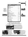
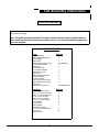
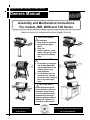
MODERN HOME PRODUCTS GAS GRILLS
Owners Manual
Assembly and Maintenance Instructions
For models JNR, WNK and TJK Series
THIS GAS APPLIANCE IS DESIGNED FOR OUTDOOR USE ONLY.
FOR YOUR SAFETY
If you smell gas:
1. Shut off gas to appliance.
2. Extinguish any open
flame.
3. Open Lid.
4. If odor continues, immediately call your gas supplier or your fire department.
FOR YOUR SAFETY
1. Do not store or use gasoline or other flammable
vapors and liquids in the
vicinity of this or any
other appliance.
2. An LP cylinder not connected for use shall not
be stored in the vicinity of
this or any other appliance.
FOR YOUR SAFETY
Follow all leak-test procedures carefully in this manual before using. Do this
even if the grill was dealer
assembled. Do not try to
light this appliance without
reading the “Lighting” instructions in this manual.
YOU MUST READ THIS OWNERS
THESE INSTRUCTIONS SHOULD BE LEFT WITH
MANUAL BEFORE OPERATING
THE CUSTOMER. KEEP THESES INSTRUCTIONS
YOUR GAS GRILL.
FOR FUTURE REFERENCE.
1
Safety
DANGER
Failure to follow the Dangers, Warnings and Cautions contained in this Owner’s Manual may
result in serious bodily injury or death, or in a fire or an explosion causing damage to property.
WARNINGS
Do not store a spare or disconnected liquid propane cylinder under or near the barbecue.
Improper assembly may be dangerous. Please carefully follow the assembly instructions in this manual.
After a period of storage, and/or nonuse, the MHP Gas Barbecue Grill should be checked for gas leaks and
burner obstructions before use. See instructions in this manual for correct procedures.
Do not operate the MHP Gas Barbecue Grill if there is a gas leak present.
Do not use a flame to check for gas leaks.
Combustible materials should never be within 24 inches of the top, bottom, back or sides of your MHP Gas
Barbecue Grill.
Do not put a barbecue cover or anything flammable on, or in the storage area under the barbecue.
Children should never use your MHP Gas Barbecue Grill. Accessible parts of the barbecue may be very hot.
Keep young children away while it is in use.
You should exercise reasonable care when operating your MHP Gas Barbecue Grill. It will be hot during
cooking or cleaning and should never be left unattended, or moved while in operation.
Should the burners go out while in operation, turn all gas valves off. Open lid and wait five minutes before
attempting to relight, using the lighting instructions.
Do not use charcoal or lava rock in your MHP Gas Barbecue Grill.
Never lean over open grill or place hands or fingers on the front edge of cooking box.
Do not enlarge the valve orifices or burner ports when cleaning the valves or burners.
The MHP Gas Barbecue Grill should be thoroughly cleaned on a regular basis.
Liquid propane gas is not natural gas. The conversion or attempted use of natural gas in a liquid propane
unit or liquid propane gas in a natural gas unit is dangerous and will void your warranty.
Do not attempt to disconnect any gas fitting while your barbecue is in operation.
Use heat-resistant barbecue mitts or gloves when operating barbecue.
LIQUID PROPANE GAS UNITS ONLY
Use the regulator that is supplied with your MHP Gas Barbecue Grill.
Do not attempt to disconnect the gas regulator or any gas fitting while your barbecue is in operation.
A dented or rusty propane cylinder may be hazardous and should be checked by your local liquid propane
supplier. Do not use a liquid propane cylinder with a damaged valve.
Although your liquid propane cylinder may appear to be empty, gas may still be present, and the propane
cylinder should be transported and stored accordingly.
If you see, smell or hear the hiss of escaping gas from the liquid propane cylinder:
1. Move away from the liquid propane cylinder.
2. Do not attempt to correct the problem yourself.
3. Call your fire department.
2
Contents
TABLE OF CONTENTS
Safety (Dangers & Warnings)……………. 2
Warranty……………………………………... 4
General Instructions………………………. 5
Mountings……………………………………. 6 -13
Cart……………………………………………….. 6 -7
Deck/Patio……………………………………….. 7-9
In-Ground………………………………………… 9
Optimum Console………………………………. 10 -11
Built-In……………………………………………. 12 -13
JNR/WNK Grill Assembly…………………. 14 -18
TJK Grill Assembly…………………………. 19 - 20
Gas & LP Tank Connections……………… 21 - 22
Leak Testing & Lighting The Grill……….. 23
Maintenance…………………………………. 24 - 26
Annual Maintenance…………………………. 24
General Maintenance………………………... 24 - 26
Tube Bending……………………………….. 26
Troubleshooting……………………………. 27
Parts Information…………………………… 28 - 31
MHP Grill upgrade options for added
versatility, convenience and cooking enjoyment.
Exclusive, rust-free anodized aluminum
cooking grids. This unique cooking system
heats up faster, reduces flare ups and cooks all
foods at a higher temperature, thereby searing
in the delicious barbeque juices. Wide-ribbed
side for grilling steaks, chops, burgers and ribs,
branding them with sear lines. The flip side, with
its smooth surface is ideal for grilling delicate
foods such as fish, seafood and vegetables.
Stainless Steel Side
Burner. The premium
commercial grade
stainless steel side
burner is 11,000 BTU
rated, has its own electronic ignition, and is factory assembled for simple
drop-in installation.
Infra-Roast™ Rotisserie
Burner System. Infra-red rear
burner heats up fast to quickly
put a seal around meats for
juicier and more moist results.
Constructed of commercial
grade stainless steel and is
easy to install or remove for
normal grilling.
3
Warranty
—————————————————————
MODERN HOME
PRODUCTS
—————————————————————–
LIMITED WARRANTY
Modern Home Products Corp. Offers to the original purchaser a Limited Warranty on all aluminum grill components
except the 7 year “SearMagic” cooking system. These components will be free from defects in material and workmanship
(excluding paint) when subject to normal domestic use and service. The highest quality paint is used where applicable,
but due to various atmosphere conditions, chemicals, fertilizers, care, cleaning and actual use, no extended warranty can
be made on paint. Also, for these reasons the limited warranty does not cover rust or aluminum oxidation, unless there is
a loss of structural integrity on the grill components.
The Stainless Steel Burner is covered for a period of 7 years, Porcelain Briquettes 5 years, all other grill components
for 1 year.
Warranty coverage begins on the original date of purchase, confirmed by return registration card and bill of sale.
Proof of purchase is required to validate warranty.
Any component that proves defective within the warranty period will, if returned to the factory freight prepaid, be repaired or replaced free of charge. Warranties shall not apply, nor will M.H.P. assume responsibility for damages that
might result from failure to follow M.H.P.’s instructions, local codes, or when the grill has been tampered with, or altered
in any way. M.H.P. shall not be liable for any transportation charges, labor costs, or export duties.
Repair or replacement of a M.H.P. gas grill part does not extend the limited warranty beyond its original term from
date of purchase, or begin a new limited warranty period.
This warranty does not include the cost of any inconvenience or property damage due to the failure of the product
and does not cover damage due to misuse, abuse, accident, damage arising out of transportation of the product, or damage incurred through commercial use of the products. This express warranty is the sole warranty given by the manufacturer and is in lieu of all other warranties, expressed or implied, including implied warranty of merchantability or fitness for
a particular purpose.
ALL WARANTIES are null & void if grills are put into
commercial or community use such as by hotels,
condominium associations, apartment committees,
etc.
Date Warranty Registration Was Mailed___________
MODERN HOME PRODUCTS CORP.
150 S. RAM ROAD
Antioch, IL 60002
MODEL IDENTIFICATION
Your MHP Gas Barbecue Grill is identified by a model number and a serial number located on the left side of the
control panel. Always use both the model and serial numbers when contacting Modern Home Products about your
grill. For future reference, take the time now to record the model and serial numbers below:
MODEL NUMBER:______________________________
SERIAL NUMBER:______________________________
DATE PURCHASED:____________________________
How to contact us: phone: 1-888-647-4745, fax: 1-800-637-2918, or E-mail: [email protected],
or write: Customer Service
Modern Home Products
150 S. Ram Road
Antioch, IL 60002
To validate your warranty, you need to fill out and send in your warranty card within 10 days. You can either
mail or Fax it to us. Or you can fill out the warranty card at our website: www.modernhomeproducts.com.
4
General Instructions
GENERAL INSTRUCTIONS
STORAGE
This installation guide provides you with easy to follow illustrations and instructions to assemble your
MHP Gas Barbecue Grill.
Turn gas OFF at the LP cylinder (or at the shut OFF
valve in the case of Natural Gas) when the MHP Gas
Barbecue Grill is not in use.
Before you start assembling and using your MHP
Gas Barbecue Grill we recommend that you read
through all precautions, safe guards and instructions to avoid any personal injury or property
damage.
Do not store spare LP cylinders under the MHP Gas
Barbecue Grill.
Store disconnected LP cylinders outdoors in a wellventilated area, do not store in shed, building, garage
or in any enclosed area.
Check Local Codes. Contact your local LP dealer or
Natural Gas company for recommended installation
procedures and regulations. If there are no local
codes, installation must conform to the latest National
Fuel Gas Code: ANSI Z 223.1. For Canada, installation must comply with local codes and/or Standard
CAN/CGA-B-149-1 for natural gas installation and
CAN/CGA- B-149-2 for propane installation.
OPERATING SAFEGUARDS
Do not install your MHP Gas Barbecue Grill
in or on recreational vehicles and/or boats.
Never use your MHP Gas Barbecue Grill near
combustible surfaces, including roof overhangs, roofs, vinyl siding and window shutters. Maintain at least a 6-foot clearance.
For LP Gas Models the supplied Gaslow GS-801
Regulator must be used. Any replacement pressure
regulator or hose assembly must meet or exceed the
specifications of the Gaslow GS-801 Regulator.
Use this barbecue outdoors in a wellventilated area.
Do not use your MHP Gas Barbecue Grill in a
shed, garage, building, breezeway or any
other confined area.
For Natural Gas Models the grill is designed to operate at a pressure of 7” water column (W.C.) (1.75
kPa). Check your gas utility for local pressure. Pressures other than approximately 7” W.C. could affect
the performance of your grill.
Do not use any kind of combustible material
on or near the top, bottom, back or sides of
the grill. Maintain at least a 2-foot clearance.
ASSEMBLY INSTRUCTIONS
There are 9 steps to assembling your MHP Gas Barbecue Grill: The mounting, LP tank mounting, control
panel, gas supply connection, grill lid, lid handle, side
shelves, and rock grate, cooking grid and warming
rack.
Leak test all gas supply line connections.
Do not let children operate a gas grill.
Keep the area around the grill clear of combustible vapors or liquids such as gasoline.
The grill itself is partially assembled with the Burner,
Venturis, Ignitor Collector Box and the Gaslow Regulator installed.
When operating the grill do not leave unattended. Keep children and pets away.
Keep fuel supply hose and electrical supply
cord away from any heated surface.
The JNR and WNK grills are specifically designed to
fit the five mounting methods: Cart, In-Ground Post,
Deck/Patio Base, Optimum Console and Built-in. The
TJK Grill is supported by the Optimum Console
mounting and Built-in.
SAFETY
YOUR GRILL IS DESIGNED FOR OUTDOOR USE ONLY.
You will need the following tools to assemble
your grill:
It should also not be used in an enclosed area such as a shed
or garage because combustion uses available oxygen and discharges carbon monoxide.
The grill must be located no closer than 24" from any combustible surface behind or to the sides. Grill should not be located
under overhead unprotected combustible surfaces.
Keep the area around the grill clear of combustible materials,
flammable vapors or liquids such as gasoline.
Do not obstruct the flow of combustion and ventilation air.
• A Phillips head screwdriver
• A standard flat head screwdriver
• Two 7/16” wrenches or sockets
5
Mountings
Step 1: Leg Assembly (Fig. 2)
Cart Assembly Instructions
(JCP, JCN, WCP & WCN)
1. Tip the grill head bottom on end as shown in Fig. 2.
(TIP: work on protected area such as: carpet, tarp or
one of the boxes to protect cart finish.)
2. Attach the two short legs to the left end of the grill
head bottom with the “Hose Ring Hole” leg facing
grill front. Use two ¼-20 x 1½" slotted bolts for each
leg. Insert bolts from inside grill box, attach leg and
fasten with ¼-20 Kep nuts.
3. Attach the two long legs to the right end of the grill
head bottom. Use two ¼-20 x 1½" slotted bolts for
each leg. Insert bolts from inside grill box, attach leg
and fasten with ¼-20 Kep nuts.
4. Attached the hose clamp ring to the front left short
leg with the 10 x 24 x ½" Rd. Hd. slotted bolt.
Cart Mounting carton contains the following
components:
Please check to be sure that all parts are included before proceeding. Contact your dealer if any parts are
missing.
Parts
Quantity
Long Legs
Short Legs
Lower Shelf Frame
Stainless Grease Cup
Grease Cup Holder
8” Rubber Wheels
Axle Hitch Pins
Axle Washers
Hub Caps
Hose Retaining Ring
LP Tank Holder Ring Assembly
2
2
1
1
1
2
2
2
2
1
1 (Propane Models Only)
Hardware Kit
¼-20 x 1 ½" Rd. Hd. Sltd. Bolts
¼-20 Kep Nuts
10-24 x ½" Rd. Hd. Sltd. Bolt
10-24 x ½" Hex Kep Nut
¼-20 Thumb Sc
¼-20 x ¾" Hex Head Bolt
12’ Natural Gas Hose
Brass Quick-Disconnect
Quick-Disconnect Dust Plug
Dust Cap
11
15
1
1
1 (Propane Cart Only)
1 (Propane Cart Only)
1 (Nat. Gas Cart Only)
1 (Nat. Gas Cart Only)
1 (Nat. Gas Cart Only)
1 (Nat. Gas Cart Only)
FINGER TIGHTEN ALL BOLTS UNTIL
LOWER SHELF IS ATTACHED.
Complete view of Cart Assembly
Step 2: Lower Shelf Assembly (Fig. 3)
1. Slip the lower shelf axle through the holes in the
short legs.
2. Slide the wheels on the axle ends, then a washer
on each, followed by a hitch pin clip through the
axle hole. Tap plastic hub cap lightly to secure
tight.
3. Align the other end of the lower shelf with the holes
in the long legs. For the JNR model, slip the axle
through the holes and fasten both ends with the
threaded ¼-20 x ¾" slotted Rd. Hd. head bolt. For
WNK model, use two ¼-20 x 1½" bolts and Kep
nuts to fasten the lower shelf to the long legs (see
Fig 3 inset).
STAND GRILL UPRIGHT TO SEAT LEGS AND
TIGHTEN ALL BOLTS AND NUTS MAKING THE LEGS &
FRAME RIGID. PERIODICALLY CHECK ALL
FASTENERS FOR TIGHTNESS.
6
Mountings
For Natural Gas Models
(Note: Tank Holder Ring is not included with natural
gas models.)
Fig. 3
If the grill is to use natural gas from the supplied 12foot hose: the hose must pass through the hose
clamp (See Fig. 1). The hose will have a quickdisconnect fitting at the source and the source will
have a gas shut off valve with easy access.
When you have completed the mount assembly
go to the appropriate Grill Assembly Section and
assemble the grill head.
Caution: Combustible material should never be
within 24 inches of the top, bottom, back or
sides of your MHP Gas Barbecue Grill.
Deck/Patio Mounting
Assembly Instructions (MPB)
•
Step 3: Tank Holder Ring Assembly For LP
Gas Models (Fig. 4)
•
•
1. The L.P. Tank Holder Ring Connects to the lower
shelf cross frame with the ring notches resting on
the axle frame.
2. Align the rear tank ring-fitting hole over the lower
cross frame hole. Insert a ¼ - 20 x 5/8" slotted bolt
through the top and fasten with a ¼ - Kep nut
from below.
3. Fasten the thumb screw (¼- 20 x ¾") to the tank
ring fitting with the ¼ - 20 Hex nuts. The Hex nut
slips into the captive slot on the tank ring fitting.
4. Use a ¼ - 20 x 1½" slotted bolt and a ¼ - 20 Kep
nut to connect the tank holder flanges together.
Either the JNR or WNK model grills may be
mounted on the Deck/Patio base.
The gas supply may be either LP or Natural.
The grill head bottom should not be attached
to the post until the mount is fasten to a
deck/patio.
Please check to be sure that all parts are included
before proceeding. Contact your dealer if any parts
are missing.
Parts
2' Post
Patio Base
Post Access Door
Grease Cup Holder
28” Stainless Steel Tubing
Stainless Steel Grease Cup
Quantity
1
1
1
1
1
1
Hardware Kit
¼ - 20 x ¾" Hex Head Bolts
¼ - 20 Kep Nuts
¼" Flat Washers
8 - 32 x ½" Self Tapping Screw
Tube Clip
7
7
7
1
1
Continue on following page. !
7
Mountings
3. Secure the gas line with the tube clip. (Option: On a
raised deck if the gas supply line is to be run straight
up into the post from below use the tube clip to attach
the gas line to the deck for support.
4. At the access door connect a 3/8" flare coupling (not
supplied by MHP) to the gas supply line and Stainless
Steel tubing. Position the tubing in the top notch of the
post. Bend the tubing at the top end to match the Feed
Line of the grill valve. Do not kink the tubing.
Step 1: Patio Base Mounting Assembly (Fig. 5)
1. Turn base on edge and insert the 2’ post. Align the
notches in the post with the notches in the base. IMPORTANT: Close tolerances may require you to tap
the top of the post to seat it completely in the base
socket which will then align the bolt slots.
2. Fasten post to base with four ¼ - 20 x ¾" Hex bolts,
washers and Kep nuts. Follow exact placement of
washers as indicated. Tighten securely.
3. Attach the tube clip with the 8 - 32 self-tapping screw
either on the right or left side of the base depending
on the direction of your gas supply line.
TUBE BENDING: For proper bending of the stainless steel
tubing, see page 26 for bending instructions.
Step 3: Attaching The Grill Head Bottom To The
Deck/Patio Post (Fig. 7 & Fig. 8)
1. To make the post-to-flange connection easier, remove the grill burner by taking out the small clip located under the bottom grill head. This will allow access to hold the Kep nuts inside the post.
2. Set the grill head bottom carefully in place, align
holes and use the ¼ - 20 x ¾" bolts and ¼-20 Kep
nuts to attach the grill flange to the post.
Step 2: Deck/Patio Mounting Installation
(Fig. 6)
Position the patio base at the desired location on a
deck or patio. CAUTION: Be certain there are no
combustible materials above, behind, left or right
closer than 24" away.
1. Mark the location of the four holes at the outside
corners of the patio base and drill four holes. The
base will be fastened down with lag bolts (not supplied by MHP) after you have connected the gas
supply line. The top post notch is the front and the
rear access door will be in the back of the grill.
2. Run the gas supply line into the post from the bottom to reach the access door and bend it 90° to
exit the base at either notch. The patio base is
notched on two sides to allow the gas line to exit
either right or left.
8
Mountings
cement (gravel) up to the gas line access hole.
Keep in mind that the gas line access hole is on
the back of the post and the notch at the top if facing front. Recheck plumb and allow cement to set.
3. Mount the grease cup holder to the rear flange hole
with a ¼ - 20 x ¾" bolt and ¼-20 Kep nut. The
grease cup holder is supplied with the grill head.
2. Run the gas supply line into the post access hole
(just above the cement). Make a 90° bend to reach
the access door opening.
The gas supply line should be trenched at least 18
inches below the surface of the ground to prevent
damage from digging. CAUTION: The gas supply
line must be regulated (in the case of natural
gas that means connected after your gas meter
and regulator) and that you have an easily accessible shut-off valve.
3. At the access door connect a 3/8" flare coupling
(not supplied by MHP) to the gas supply line and
Stainless Steel tubing. Position the tubing in the top
notch of the post. Bend the tubing at the top end to
match the Feed Line of the grill valve. Do not kink
the tubing.
When you complete the mount assembly go to
the appropriate Grill Assembly Section and assemble the grill head.
In-Ground Mounting
Assembly Instructions (MPP)
•
•
•
•
Either the JNR or WNK model grills may be
mounted on the In-Ground Mounting base.
The gas supply may be either LP or Natural.
To protect against corrosion, you must apply
a suitable coating on the post to retard the
effects of corrosion existing in local areas.
The grill head should not be attached to the
post until the post is permanently cemented
in ground.
Please check to be sure that all parts are included before proceeding. Contact your dealer if any parts are
missing.
Parts
4' Post
Post access door
28” Stainless Steel Tubing
Stainless Steel Grease Cup
Stainless Grease Cup Holder
¼ - 20 x ¾" Hex Head Bolts
¼ - 20 Kep Nuts
Quantity
1
1
1
1
1
3
3
TUBE BENDING: For proper bending of the stainless steel
tubing, see page 26 (Fig. 47) for bending instructions.
Step 2: Attaching The Grill Head Bottom To
The In-Ground Post (Fig. 7 & 8)
Step 1: In-Ground Mounting Installation (Fig. 9)
To attach the grill head to the post please refer to Step
3 of the Deck/Patio installation procedures on page 8
and follow instructions.
1. Dig a posthole about 8 inches wide by 2 feet
deep. Caution: Locate the hole so that the
mounted grill head has a clearance of 24
inches away from any combustible object or
surface; above, back, left or right.
Center the post in the hole and plumb it. Pour in
When you complete the mount assembly Go to the
appropriate Grill head section and assemble the
Grill Head.
9
Mountings
Stainless Steel Optimum Console
Assembly Instructions
•
•
•
•
The JNR, WNK or TJK model grills may be
mounted on the Optimum Console.
The gas supply may be either LP or
Natural.
The grill head should not be attached to the
Optimum Console until the console is
completely assembled
The Optimum Console comes in two cartons—Box A contains the console and all
associated hardware. Box B contains either
the pedestal or cart base and all base
hardware.
Step 1: Connect the Tank Locking Bar (Fig. 10)
1. From box “A” locate and attach the Tank Lock Bar
across the back of the pedestal column. Use the ¾"
S.S. Hex bolt, Nylon Lock Bar Spacer and a Kep nut
on each side to fasten the Tank Lock Bar in place.
This spreads and holds the correct spacing at the
back of the column.
Please check to be sure that all parts are included
before proceeding. Contact your dealer if any parts are
missing.
Parts
Quantity
BOX A
Stainless Steel Front Panel
Stainless Steel Console
Stainless Grease Cup
Tank Lock Bar
1
1
1
1
Hardware Kit
Nylon Lock Bar Spacers
¼ - 20x1¼" S.S. Hex Head Bolts
¼ - 20 S.S. KEP Nuts
¼ S. S. Washers
¼ - 20 x ¾" S.S. Hex Bolts
Rectangular Washers
2-piece Gasket
2
4
12
10
8
4
1
BOX B
Cast Aluminum Base
12’ Nat. Gas Hose/Quick Discount
1
1 (Cart Nat.
Stainless Steel Flexible Tubing, 28”
1 (Pedestal Nat.
Axle
Axle Clips
6 " Wheels
Hub Caps
1 (Cart Only)
2 (Cart Only)
2 (Cart Only)
2 (Cart Only)
Step 2: Attach the Base to the Pedestal (Fig. 11)
1. Before bolting the pedestal column to the base, the
2-piece gasket must be installed to create a barrier
between the two metals. Remove the backing strips
from the gasket to expose the adhesive and stick
the gasket to the bottom lip of the pedestal column.
Make sure to align the holes.
2. Attaching the pedestal column to the base will be
easier to handle by laying the pedestal column face
down and matching the holes on the pedestal column lip to the holes on the base. Use six ¾” bolts,
four large rectangular washers, and on the underside six round washers and KEP nuts.
IMPORTANT: the large rectangular washers are
used at the sides on top of the pedestal column lip.
The round washers and KEP nuts are used under
the base. Tighten securely and stand unit upright.
Gas Only)
Gas Only)
Note: While assembling, peel the thin white protective film
covering the stainless steel surfaces, especially in areas
which will be partially hidden after assembled. Do Not
Scrape off.
10
Mountings
OPTION: For OPTIMUM Cart Only: (Fig. 12)
Step 4: Attaching the Access Panel (Fig. 14)
1. Attach the wheels by slipping the axle through the
base, slide the wheels on and secure with the axle
clips. Finish by snapping the hub caps on before
standing unit upright.
Note: Do not attach the front access panel until
the control panel has been attached to the
grill head bottom and the gas supply line
has been properly connected and leak
tested.
1. The front access panel attaches directly under the
control panel and hides the access opening. Lift
the access panel up behind the lip of the control
panel, then slip the bottom double edge of the access panel (upward pressure may be needed) over
the edge of the access opening.
Step 3: Connect the Grill Head Bottom (Fig. 13)
1. Attach the grill head bottom to the pedestal column
top with four ¼ - 20 x1 ½" Hex bolts, washers under
the bolt head and Kep nuts. Peel the remaining
protective coating off the pedestal column.
When you complete the mount assembly go to the
appropriate Grill Assembly Section and assemble
the grill head.
Caution: Combustible material should never be
within 24 inches of the top, bottom, back or sides
of your MHP Gas Barbecue Grill.
11
Mountings
Complete View Of Built-In
Built-in Kit Mounting
Assembly Instructions (NMS)
•
The JNR, WNK or TJK model grills may be
mounted as a built-in.
• For use with natural or hard–plumbed propane
gas.
• Use of the Built-in kit for LPG poses a safety
risk and voids any and all warranty.
• Enclosure must be constructed from non combustible materials.
• The Built-In kit and grill head connection will
be assembled upside down.
• Refer to appropriate section for grill head assembly.
Please check to be sure that all parts are included before proceeding. Contact your dealer if any parts are
missing.
Parts
Quantity
Set of doors with magnetic catches
Consisting of:
Frame for Door Set
1
Left Hand Door
1
Right Hand Door
1
Heat Shield
1
Magnetic Catches
2
Door Handles
2
Front Face Plate for NMS (26" W x 11" H x 1½" D) 1
Right Side “L” Bracket 19" x 11"
1
Left Side “L” Bracket 19" x 11"
1
Rear Support Bracket 26 1/8" long
1
Grease Tray
1
Hardware Kit
¼ - 20 x ¾" Hex lts
¼ - 20 x 1 ¼" Hex Bolts
¼" Nuts
¼" Flat Washers
¼" Lock Washers
Step 1: Required Dimensions For Built-In
(Fig. 16)
1. The grill head fits into an opening of 27½" wide by
10¾" high by 18" deep.
2. The Panel doors fit into an opening of 27¼" wide by
16¾" tall.
3. The side burner fits a surface opening of 10¼" wide
by 11¾" front to back. It should be at least 5" away
from the grill opening.
(The front face flanges on the mounting and the panel
doors overlap the required opening surfaces by 15/8"
and provide a clean look.)
12
4
4
4
16
Important Notes:
Your structure should have a 3" to 4" concrete base on a
sand footing.
The panel doors must have a 4" to 6" minimum elevation
from the ground.
If your structure includes a back splash, allow 11" to the
back edge of grill opening to allow the lid to open completely.
Combustible material should never be within 24 inches of
the top, bottom, back or sides of your Grill.
12
12
Mountings
Step 2: Built-In Mounting Assembly
Note: Be certain that the gas pressure is
between 6.5" and 7.5" water column. Excess
gas pressure can cause warping and damage to
grill head.
6. When finished connecting gas supply, slide grill all
the way into to opening so that the “L” bracket face
flanges fit snuggly to your enclosure face. Drill a
hole in the masonry to match up with the “L” bracket
face flange holes and fasten with lag bolts (not
supplied).
Do not build a shelf below the bottom of the
grill. The grill requires an open area for proper
ventilation and service access.
7. Install the pre-assembled door kit by securing with a
suitable fastening method. (Anchors and/or screws
not included.)
IMPORTANT: Since the mounting is attached directly
to the grill, you must first partially assemble your grill
by attaching the control panel to the grill head (refer to
the appropriate grill section for assembly instructions).
Then the built-in mounting heat shield must be attached to the bottom of the grill head using four ¼-20 x
¾" bolts, see fig. 14 “Complete View” illustration.
Do not forget to remove the protective film from all
stainless steel parts of your built-in mount.
To assemble the built-in frame (Fig. 17)
1. Align the holes of the right hand “L” bracket with the
face panel (the face panel’s 12 vent slots should be
on the top) and insert two 1/4 x ¾" Hex bolts and
fasten with flat washer, lock washer and nut, do not
tighten at this time. When properly connected the
grill support tabs on the “L” bracket should be facing
up and inward.
2. Repeat procedure to connect the left hand “L”
bracket.
3. Attach the rear bracket to both the right and left “L”
brackets using two ¼ - 20 x ¾" Hex bolts at each
end. Secure bolts with a flat washer, lock washer
and nut.
4. Attach the frame to the bottom grill head by aligning
the frame support tabs with the grill head bottom
holes. Insert the ¼ - 20 x 1 ¼" Hex bolt from inside
the grill head and screw it into the threaded frame
support tab.
When you complete the mount assembly go to
the appropriate Grill Assembly Section and finish assembling the grill head.
To connect the full assembly to the enclosure.
5. Slide the grill head into the opening 3/4 of the way
in. Connect the gas supply using an approved outdoor connector. Check for gas leaks. (See Gas
Leaks page 23.)
13
JNR & WNK Assembly Instructions
CARTON CONTENTS
Please check to be sure that all parts are included before proceeding with assembly. Contact your local dealer
if any parts are missing.
Note: The grill is partially assembled. The Burner, Spider Guards, Venturis, Ignitor Collector
Box are installed. Also, for LP units the Gaslow Regulator and Hose are installed.
MODEL JNR GRILL
Parts
Top Casting (Grill Lid)
Bottom Casting (Grill Head)
Sta-Kool Handle
Handle End Caps
Warming Rack
Bottom Grate
Porcelain Cooking Grids
Control Panel Brackets
Heat Shield
Grease Cup Holder
Control Panel Assembly
Valve Control Knobs
Ignitor Knob
Side Shelf
Side Shelf Bracket
Venturi Tube Cleaning Brush
Bag of Briquettes (53 pieces)
Meat Probe
Forked Grid Cleaning Tool
Hardware
Connecting Wire for Ignitor
¼-20 x 1½" Rd. Hd. Sltd. Bolt
¼-20 x ½" Rd. Hd. Sltd. Bolt
¼-20 x ¾" Hex head Bolts
¼-20 x 1" Hex head Bolts
¼-20 x 1½" Hex Head Bolt
¼-20 KEP Nut
Keeper Washer
Graphite Washer
Flat Washer for Ignitor
1/8-27 Jam Connecting Nut
Lid Pivot Pin
Hitch Pin for Lid
MODEL WNK GRILL
Quantity
Parts
1
1
1
2
1
1
1 (SearMagic 2)
2
1
1
1
2
1
1
1
1
1
1
1 (SearMagic Only)
Top Casting (Grill Lid)
Bottom Casting (Grill Head)
Sta-Kool Handle
Handle End Caps
Warming Rack
Bottom Grate
Stainless Steel Cooking Grids
Control Panel Brackets
Heat Shield
Grease Cup Holder
Control Panel Assembly
Valve Control Knobs
Ignitor Knob
Side Shelf
Side Shelf Bracket
Venturi Tube Cleaning Brush
Bag of Briquettes (63 Pieces)
Meat Probe
Forked Grid Cleaning Tool
Quantity
Hardware Kit
1
4
2
3
4
2
11
2
2
1
1
2
2
Connecting Wire for Ignitor
¼-20 x 1½" Rd. Hd. Sltd. Bolt
¼-20 x ½" Rd. Hd. Sltd. Bolt
¼-20 x ¾" Hex head Bolts
¼-20 x 1" Hex head Bolts
¼-20 x 1½" Hex Head Bolt
¼-20 KEP Nut
Keeper Washer
Graphite Washer
Flat Washer for Ignitor
1/8-27 Jam Connecting Nut
Lid Pivot Pin
Hitch Pin for Lid
14
Quantity
1
1
1
2
1
1
2 (SearMagic 3)
2
1
1
1
2
2
2
2
1
1
1
1 (SearMagic Only)
Quantity
1
6
2
3
8
2
13
2
2
1
1
2
2
JNR & WNK Assembly Instructions
Grill Head Assembly
Instructions
•
•
•
•
•
The grill head bottom must be attached to
the mounting before starting.
It is easiest to work with the grill in the upright position.
The difference between the JNR and the
WNK is the WNK is larger, has two side
shelves and the warming rack fastens differently.
Leak test all gas connections before
using.
Caution: Combustible material should
never be within 24 inches of the top, bottom, back or sides of your MHP Gas Barbecue Grill.
B. Connecting the Control Panel Support Brackets
(Fig. 20)
1. Two support brackets are connected beneath the
control panel to the grill head for added support.
Push a ¼ - 20 x 1¼" Phillips head bolt through the
grill head from the inside.
2. Slip the support bracket in position, fasten with a
¼ - 20 Kep nut.
3. Attach the control panel to the support bracket by
pushing up a ¼ - 20 x ½" Phillips head bolt through
the support bracket and through the lower lip of the
control panel, fasten with a ¼ - 20 Kep nut.
View of JNR & WNK Grill Head Components
Step 1: Control Panel & Heat Shield
A. Attaching Heat Shield and Control Panel (Fig. 19)
1. Insert the ¼ - 20 x ¾" Hex bolts through the two
holes in the front of control panel.
2. Press a keeper washer to hold the bolts in place.
3. Slip the control panel shield onto the bolts.
4. Attach the complete control panel assembly to the
front of the grill head with a ¼ - 20 Kep nut.
5. Make sure the valve orifices on the control panel
aligns with the burner venturi correctly and that the
venturi tubes go over the valve orifices at least ¼" to
½" (see fig. 22 on page 16).
15
JNR & WNK Assembly Instructions
C. Ignitor Wire Connection (Fig. 21)
Step 2: Connect the gas supply line (Fig. 23)
1. Tip the grill on its back (or upside down) and attach
the control panel ignitor wire to the terminal sticking out from the bottom of the grill. Be careful not
to crack the delicate porcelain insulator.
A. For LP-Gas Tank and LP Cart Models:
1. Pass the Gaslow Regulator Hose through the
hose clamp ring and screw the ring to the front of
the left leg.
2. Connect the regulator end of the hose to the LPGas Tank. Tighten securely and leak test both
connections. See Leak Testing on page 23.
B. For Natural Gas Cart, Deck/Patio and InGround Mounts Using 12 foot Hose:
Connect one end of the supplied 12 foot hose to the
grill valve connection behind the control panel. Then,
connect the quick disconnect valve on the hose to the
gas supply line connection. Tighten securely and
leak test both connections. See Leak Testing on
page 23.
Do not allow the
gas hose
to come in
contact
with the
bottom of
the grill
head.
D. Orifice Engagement (Fig. 22)
At the top end of each valve there is a tiny gas opening known as the orifice. Gas exits the orifice and
enters a venturi where it mixes with air coming in from
the side air shutter. The proper mixture of air and gas
produces a clean blue flame at the burner.
Make sure the valve orifice on the control panel aligns
with the burner venturi tube correctly. The orifice
should fit into the venturi tube ¼" to ½" inches as
shown below.
C. For Deck/Patio & In-Ground Mounts Using 30"
Flexible tubing. (Fig. 24)
Connect the 30" flexible tube to the incoming gas
supply using a 3/8" flare coupling (not supplied). Attach the other end to the grill valve connection behind
the control panel. To tighten securely use two
wrenches. Hold valve joint with one wrench and
tighten the hose fitting with second wrench. After
Tighten leak test both connections. See Leak
Testing on page 23.
WARNING! Always check the alignment of the orifice
and the venturi whenever the grill has been moved.
Make sure that the orifice fits into the venturi tube
1/4" to 1/2". Failure to make this connection may
cause fire and result in serious body injury or damage to your grill.
Do not use compound
or Teflon tape on flare
fittings.
16
JNR & WNK Assembly Instructions
Step 2: Continued
Natural gas hose for Optimum cart mount:
D. Optimum Console Mount Gas Connections
The natural gas cart
uses a 12 foot hose with
a quick disconnect
(supplied). The hose
passes beneath the heat
shield through the front
access opening and
connects directly to the
control valve. The quick
disconnect end attaches
to the gas supply line at
the shut-off valve.
(Fig. 28)
All Optimum Console mounts:
The supply line connection pass beneath the heat
shield and through the
front slot with the protected edge and attaches to the valve.
Don’t forget to attach the
front Access Panel to
the Optimum Console.
(Fig. 25)
LP Propane for Optimum cart and pedestal
mounts:
The hose connection
from the Gaslow/
Regulator passes out the
front access opening;
resting on the protected
slot edge beneath the
control panel. The LP
tank locking bar will
press against the tank as
it is lowered into place to
prevent tank movement.
(Fig. 26)
Step 3: Attaching the Side Shelf (Fig. 29)
1. Turn NuStone Shelf upside down, noting the hole
location of the (2) Brass Treaded Inserts.
2. Lay Aluminum side shelf bracket onto shelf and
mount NuStone Shelf with supplied ¼-20 x 1¼"
Phillips head bolt and Lock washers. Do not
over tighten.
3. Attach the entire unit to the grill head by inserting
two ¼-20 x 1½" Rd. Hd. Sltd screws. Insert bolt
through the holes located on either the right or left
side of the bottom grill head, fasten with a ¼-20
Kep nut.
(Note: Repeat steps 1 and 3 to attach the WNK
model second side shelf.)
Natural gas for Optimum pedestal mount:
The gas line enters at the rear of the base curving up
through the base opening.
The stainless steel flexible
tubing line must be connected to the incoming gas
line using a 3/8" flare coupling (not supplied by
MHP). The flexible tubing
then passes beneath the
heat shield and through
the front access opening
and attaches to the control
valve. (Fig. 27)
See page 26 for tubing
bending instructions.
Tighten all gas connections securely and leak test
both ends. See Leak Testing on page 23.
17
JNR & WNK Assembly Instructions
Step 4: Attaching the Grill Lid (Fig. 30)
1. Attach the grill lid to the grill head bottom using the
two Hinge Pins and Hinge Clips.
Step 7: Warming Rack
Step 5: Connect the Handle (Fig. 31)
1. Attach the handle to the grill lid using two ¼ - 20 x 1
½" Hex bolts with Kep nuts. Graphite Gaskets are
positioned between the end caps and grill lid as
shown in fig. 31.
Use two 7/16" wrenches, one to hold the bolt head
and one to tighten the nut.
1. The JNR
Warming Rack
rests in the
notches on the
top edge of the
grill head bottom. (Fig. 33)
2. The WNK swingawayWarming Rack connects to the
grill lid and the
grill head bottom. First, insert
the right Top
and Bottom
Rods into their
respective
mounting holes
on right side of
the grill lid and grill head bottom. Then slide the
RACK to your left, positioning the left Top and Bottom
Rods into their respective mounting holes simultaneously. The Lower Right Rod End can then be
“popped” into place by flexing it inward. (Fig. 34)
Step 6: Grates, Briquettes and Cooking Grids
(Fig. 32)
1. Place the one piece Briquette Grate on the shelf
edge just above the burner.
2. Carefully place the Ceramic Briquettes on the grate
in the pattern shown. Use only one layer.
3. Place the two Cooking Grids above the Briquette
Grate.
3. The SearMagic Warming
Rack drops onto the top
edge of the grill head
bottom. the warming rack
bracket is positioned between the hinges of the
grill head bottom inside
back wall. (Fig. 35)
Before using your grill, leak test all gas line
connections. And follow the lighting instructions. See page 23.
18
TJK Assembly Instructions
CARTON CONTENTS
Please check to be sure that all parts are included before proceeding with assembly. Contact your local dealer
if any parts are missing.
Note: The grill is partially assembled. The Burner, Spider Guards, Venturis, Ignitor Collector
Box and the Stainless Steel Handle are installed. Also, for LP units the Gaslow Regulator and
Hose are installed.
MODEL TJK Grill
Parts
Quantity
Top Lid Assembly
Bottom Casting (Grill Head)
Warming Rack
Bottom Grate
Stainless Steel Cooking Grids
Control Panel Brackets
Heat Shield
Grease Cup Holder
Control Panel Assembly
Valve Control Knobs
Ignitor Knob
Stainless Steel Side Shelf
Side Shelf Bracket
Condiment Holder
Venturi Tube Cleaning Brush
Bag of Briquettes (67 pieces)
Meat Probe
Forked Grid Cleaning Tool
Hardware
1
1
1
1
2 (SearMagic 3)
2
1
1
1
2
2
2
2
2
1
1
1
1 (SearMagic Only)
Quantity
Connecting Wire for Ignitor
¼-20 x 1½” Rd. Hd. Sltd. Bolt
¼-20 x 1¼” Rd. Hd. Sltd. Bolt
10-24 x 1¼” Rd. Hd. Bolt
¼-20 x ¾” Hex Head Bolt
¼-20 x ½” Rd. Hd. Sltd. Bolt
10-24 KEP Nut
¼-20 KEP Nut
Keeper Washer
Flat Washer for Ignitor
1/8 – 27 Jam Connecting Nut
Lid Pivot Pin
Hitch Pin for Lid
19
1
2
4
8
3
2
8
11
2
1
1
2
2
TJK Assembly Instructions
Grill Head Assembly
Instructions
•
•
•
•
The grill head bottom must be attached to
the mount before starting.
It is easiest to work with the grill in the
upright position.
Leak test all gas connections before using.
Caution: Combustible material should never
be within 24 inches of the top, bottom, back
or sides of your MHP Gas Barbecue Grill.
Complete View of TJK Grill
Step 4: Attaching the Grill Lid
(See JNR/WNK instructions on page 18, Fig 30.)
Step 5: Grates, Briquettes and Cooking Grids
(See JNR/WNK instructions on page 18, Fig. 32)
Step 6: Warming Rack (Fig. 38 & 39 )
1. The Warming Rack connects to the grill lid and the
grill head bottom. First, insert the right Top and Bottom Rods into their respective mounting holes on
right side of the grill lid and grill head bottom. Then
slide the RACK to your left, positioning the left Top
and Bottom Rods into their respective mounting holes
simultaneously. The Lower Right Rod End can then
be “popped” into place by flexing it inward.
IMPORTANT: Most of the TJK Model major
component assembly is the same as the JNR/
WNK Models. Please refer to the JNR/WNK
assembly instructions as indicated.
Step 1: Control Panel & Heat Shield
(See JNR/WNK instructions on page 15, Fig. 19 & 20)
Step 2: Connect The Gas Supply Line
(See JNR/WNK instructions, item D on page 17, Figs.
25-28)
2. The SearMagic Warming
Rack drops onto the top
edge of the grill head
bottom. The warming rack
bracket is positioned between the hinges of the
grill head bottom inside
back wall.
Step 3: Attaching the TJK Side Shelf (Fig. 37)
1. Fasten the Shelf Bracket to the Right side of grill
head bottom with two ¼-20 x 1¼" Rd. Hd. Sltd
bolts and ¼-20 Kep nuts.
2. Attach the Shelf and the Condiment Holder to the
Brackets. All four 10-24 x 1¼" bolts should be inserted into the bracket before tightening them with
10-24 Kep nuts..
(Note: Repeat steps 1 and 2 to attach the other
side shelf.)
Before using your grill, leak test all gas line
connections. And follow the lighting instructions. See page 23.
20
Gas & LP Tank Connections
LP Gas Cylinder Requirements: (The LP-Gas Cylinder is not supplied with your MHP Grill.)
• The LP cylinder should be equipped with an OPD
(Overflow Prevention Device) and a QCC! Or Type
1 (CGA810) cylinder connection. This cylinder connection is compatible with the grill connection. OPD
is an internal mechanical device that limits the
amount of liquid propane and prevents overfilling
the LP cylinder. The correct filling methods for the
filling of your cylinder are by weight or volume, as
described in NFPA 58. Please make sure your LP
dealer fills your LP cylinder by weight or volume.
Ask your LP dealer to read purging and filling instructions on the LP cylinder before attempting to
fill.
• All LP cylinders supply systems must include a collar to protect the cylinder valve.
• The LP cylinder must be a 20-LB size (18 1/4 “
high, 12 ¼” in diameter).
• The LP cylinder must be constructed and marked
in accordance with the specifications for LP-gas
cylinders of the U.S. Department of Transportation
(D.O.T.). In Canada, gas cylinders must meet Canadian LP Gas Tank Specification Code, National
Standard of Canada, CAN/CSA-B339, Spheres
and Tubes for the Transportation of Dangerous
Goods and Commission.
• Be sure your LP cylinder has a D.O.T. certification
and has been tested within five years. This information is usually marked on the protective collar.
GAS & LP CYLINDER
Check Local Codes
Consult your local LP dealer or Natural Gas Company
for recommended installation procedures and regulations. In the absence of local codes, installation must
conform to the National Fuel Gas Code, ANSI Z223.1
or CAN/CGA-B149.1 Natural Gas Installation Code or
CAN/CGA-B149.2, Propane Installation Code.
Natural Gas Models
The grill is designed to operate on Natural Gas at a
pressure of 7” water column (W.C.) [1.75 kPa]. Check
with your gas utility for local gas pressure. Use of your
gas grill at pressures other than approximate 7” WC
could affect the performance of your grill.
Natural Gas Hose & Inspection
A single hose of not more than 12 feet long (3.6 meters) is supplied with the cart-styled models.
• Check the hose before each use at places where
there could be extra bending, such as near the gas
supply quick-disconnect coupling and at the grill
valve connection. Look for cracking, cuts or heat
damage. Check the entire length for cracking and
excessive wear.
• To replace the hose, turn off gas supply at valve.
Release the quick-disconnect coupling. Using a
wrench, disconnect hose from grill valve connection
under the control panel, and clean threads.
• Replace only with an identical hose from the manufacturer or an authorized dealer. Do not use pipe
joint compound on the flared fitting at the control panel grill valve connection.
WARNING: If you use an LP tank exchange
service, be sure that the exchanged tank is
equipped with an OPD. If there is not an LP
tank available for exchange equipped with
an OPD, we recommend that you have your
LP tank filled by an authorized LP dealer.
LP Gas Models
The Grill using a Type I LP cylinder includes the
Gaslow Regulator that incorporates an industry exclusive Leak Detector and Fuel Supply Indicator. Any
replacement pressure regulator or hose assembly
must meet or exceed the specifications of the Gaslow
Regulator.
DO NOT CONNECT THE GRILL TO AN LP
GAS CYLINDER GREATER THAN 20 LB.
CAPACITY.
DANGER
Do not use an open flame to check for gas
leaks. Be sure there are no sparks or open
flames in the immediate area while you check
for leaks. Sparks or flames will result in a fire or
explosion which can cause serious bodily injury
or death, and damage to property.
21
Gas& LP Tank Connections
LP-GAS CYLINDER FILLING & HANDLING (Continued)
• Air must be removed from a new LP cylinder before
the initial filling. Your LP dealer is equipped to do this.
• The cylinder supply system must be arranged for vapor withdrawal
• Always keep and store cylinders in an upright, secure
position.
• Use this grill outdoors in a well-ventilated area. Do not
use in a garage, building, or any other enclosed area.
• Storage of an outdoor cooking gas appliance indoors
is permissible only the cylinder is disconnected and
removed from the outdoor cooking gas appliance.
• If the outdoor cooking appliance is not in use, the gas
must be turned off at the supply cylinder.
• Cylinders must be stored outdoors out of reach of children and must not be stored in a building, garage or
any other enclosed area.
CONNECTING THE LP CYLINDER (Fig. 40)
1. Slip the LP cylinder into the grill LP Tank Mounting.
Position the LP cylinder so that the tank valve receives the regulator without kinking or creating
sharp bends in the hose. Secure the tank to the grill
base. For cart base models fasten the mounting
thumbscrew to secure the tank in place. The Optimum Console base models has the LP Tank Locking Bar to hold the LP Cylinder in place (refer to
mounting section for detail).
2. The Gaslow Regulator has a large plastic nut QCC-1 fitting - for hand tightening (no tools required) and a RIGHT HAND THREAD (turn clockwise). Connect the regulator to the cylinder by inserting the regulator nipple into the tank valve.
Tighten the large plastic nut CLOCKWISE by
hand until secure.
LP GAS CYLINDERS SAFE HANDLING TIPS
REMOVAL OF THE LP CYLINDER (Fig. 38)
1. Close the LP tank valve.
2. Unscrew the QCC-1 plastic nut BY HAND COUNTERCLOCKWISE (to the left).
3. Loosen the LP cylinder from the Tank Mounting
4. Lift cylinder off.
WARNING: If you exchange your LP cylinder,
make sure you get a similar tank in return.
Your exchanged LP cylinder must be equipped
with a QCC-1 or type-1 valve and an OPD
(Overflowing Prevention Device). Other LP cylinders may not be compatible with your grill connection.
LP-GAS CYLINDER FILLING & HANDLING
A qualified attendant, who fills the cylinder by weight,
should fill your LP cylinder at an authorized LP gas
dealer. Improper filling is dangerous.
• When transporting the LP cylinder be sure the plastic
dust cover is in place over the valve. This keeps the
valve threads free of dirt.
• Do not handle the cylinder roughly.
• Do not apply heat directly to the cylinder.
• Liquid propane (LP) gas is a petroleum product as are
gasoline and natural gas. LP gas is a gas at regular
temperatures and pressures. Under moderate pressure, inside a cylinder, LP gas is a liquid. As the pressure is released, the liquid readily vaporizes and becomes gas.
• LP gas has an odor similar to natural gas. Be aware
of this odor.
• LP gas is heavier than air. Leaking gas collects in low
areas and prevents dispersion.
• To fill, take the LP cylinder to your local authorized LP
dealer, or look up “gas-propane” in the yellow pages
to find authorized dealers.
• A new LP cylinder must be purged before the first filling. Your LP dealer is equipped to do this.
• An LP cylinder must be transported, installed and
stored in an upright position.
• LP cylinders should not be handled roughly.
• Never store or transport an LP cylinder where the
temperatures can reach 125 degrees. Never leave an
LP cylinder in a car on a hot day.
• Always close the LP cylinder valve before disconnecting the tank or any other gas fitting.
• Always close the LP Cylinder valve after using grill.
• Do not use a damaged LP cylinder. Dented, rusty or a
damaged LP cylinder valve may be hazardous and
should be replaced with a new one immediately.
• Never fill the LP cylinder beyond 80% full.
• Do not store a spare LP gas cylinder under or
near the grill.
If this information is not followed exactly, a fire
causing death or serious injury may occur.
22
Leak Testing & Lighting Grill
Leak Testing
Lighting Your Grill
LEAK TEST ALL GAS CONNECTIONS BEFORE USING YOUR GRILL.
ALWAYS OPEN GRILL BEFORE LIGHTING THE
BURNER.
DO NOT SMOKE WHILE LEAK TESTING.
DO NOT LEAN OVER AN OPEN GRILL. KEEP
YOUR HEAD AND BODY AT LEAST ONE FOOT
AWAY WHEN LIGHTING THE GRILL.
DO NOT LEAK TEST WITH A MATCH OR
OPEN FLAME.
IF BURNER DOES NOT LIGHT, IMMEDIATELY
TURN BURNER CONTROL KNOBS TO OFF.
WAIT FIVE MINUTES TO LET GAS CLEAR BEFORE YOU TRY LIGHTING AGAIN.
DO NOT USE A GRILL THAT IS LEAKING GAS.
YOU SHOULD TEST FOR GAS LEAKS EVERY
TIME YOU DISCONNECT AND RECONNECT A
GAS FITTING.
LIGHTING
1. Open Lid. Examine the interior to be sure it appears
normal.
2. Turn burner control knobs to OFF position.
3. Turn gas ON at LP tank or supply. Wait 5 seconds
for regulator to set itself.
4. Turn either burner control knob to HIGH and rotate
the ignitor knob CLOCKWISE several times. One half
of the burner should light. Turn the other burner control knob to HIGH and the other half of the burner will
light automatically.
5. Check that the burner is lit by looking through the
match light hole on the lower right hand side. The
burner flame should be a hard blue cone with a minimum amount of yellow flame, although some yellow
dust flicks may occur.
PERFORM A LEAK TEST EVEN IF YOUR
GRILL WAS DEALER OR STORE ASSEMBLED.
DO NOT IGNITE BURNERS WHEN LEAK
TESTING.
LEAK TESTING
1. For LP models, leak test with a full propane cylinder.
2. For systems other than self-contained LP cylinders:
A. The grill and its individual shut-off valve must
be disconnected from the gas supply piping
systems during any pressure testing of that
system at test pressures in excess of 1/2 psi
(3.5 kPa).
B. The grill must be isolated from the gas supply
piping system by closing its own manual shut
off valve during any pressure testing of the gas
supply piping system at pressures equal to or
less than 1/2 psig (3.5 kPa).
1. Grill burner control valves should be turned off and
the gas turned on at source.
2. Apply soap solution to all gas connections.
To make soap solution, mix together equal
amounts of liquid detergent and water.
3. Soap bubbles will appear if there is a leak.
4. Tighten the connection to make proper seal. And
recheck for soap bubbles.
6. Close the grill lid and pre-heat the grill for five to ten
minutes before cooking.
WARNING: If burner fails to light, turn control knobs
OFF and wait five minutes for gas to clear and try
lighting procedure again.
To light burner manually, use a paper book match or
other hand held ignitor. Insert match through lower right
side match hole. Turn on the RIGHT burner control knob
to the high setting. Light burner.
If you cannot stop a gas leak by tightening,
turn gas supply off. Take leaking joint apart,
clean it, reconnect and test again. If leak
persists, contact the dealer or gas utility.
A gas system MUST be tested yearly, or
whenever the LP cylinder or any other gas
system part is replaced.
To Extinguish your grill: Turn each burner control knob
to OFF position. Turn gas supply OFF at the source.
23
Warning: Check the hose before each use of the grill for nicks,
Maintenance
cracking, abrasions or cuts. If the hose is found to be damaged in
any way, do not use the grill. Replace using only MHP authorized
replacement hose.
Annual Maintenance
General Maintenance
After a period of nonuse or to keep your grill in top
operating condition, you should perform the following
maintenance procedures to keep the grill ready for
instant use and for your safety.
• Do not obstruct the flow of combustion and ventilation air.
• Clean inside the grill head. Remove the burner/
venturi assembly and cover the valve orifices with a
piece of aluminum foil to keep out dirt. Brush inside
bottom and sides with a stiff wire brush to remove
built-up grease and debris. Be careful not to damage the Ignitor or Collector Box.
• Test the Ignitor for a good spark. (See Rotary
Spark Ignitor System in the General Maintenance
section.)
• The stainless steel burner may be brushed lightly
with a stiff laundry brush. Any clogged flame holes
may be opened using a thin wire. Use the supplied
venturi cleaning brush or a bottle brush, pipe
cleaner to clean out the venturis. (See Flashback in
General Maintenance.)
• Clean the Control Panel, Side Shelf Supports, Lid
Handle Spacers, Lower Cart Frame, Posts with a
mild detergent soap and warm water solution. For
the Optimum Console use a mild detergent soap
and water, Windex or a quality stainless steel
cleaner such as MHP’s Stainless Steel Cleaner
(Part #SSC) to clean the column and grill lid facing.
Do Not Use cleaning agents such as bleach,
powdered cleansers, steel wool pads or caustic
solutions like oven cleaners because they will
damage the surfaces.
• Porcelain cooking grids should be cleaned by first
pre-heating the grill on high for ten minutes, lid
closed. Then with a brass bristled grill brush clean
off the debris. Do Not wash the porcelain grates in
a sink or dishwasher. It may ultimately cause the
porcelain to chip.
• Occasional white oxidation on the exterior of your
grill head and lid may be washed off with mild soap
and warm water.
• Severe weathering of the grill head and lid can be
remedied by lightly sanding or rubbing with steel
wool. Then it can be recoated with a high quality
heat resistant paint similar to MHP’s BF-1 Paint,
available in spray cans from your dealer.
• Inspect the hose and gas fittings. Remember to
leak check every time you disconnect and reconnect a gas fitting.
• Keep the ventilation openings of the LP cylinder
enclosure free and clear from debris.
Flashback
In some areas of the country, spiders and other insects build nests, lay eggs and spin webs in the grill’s
venturi tube or valve orifice. This obstructs the full flow
of gas to the burner. Some gas backs up resulting in a
“Flashback” - a fire in the venturi behind the control
panel which could cause serious bodily injury or damage to your grill.
To remove spider webs and/or other obstructions, you
must clean out the venturis. This should be done
routinely if the grill has sat idle for extended periods. Also, if you live in an area where spiders are
plentiful, you should clean the venturis often, especially in the fall when there is an increase in egg
sack production.
To clean, be sure the grill is cold. Open lid and remove the cooking grids, the briquettes and the briquette grate.
1. Remove the burner clip holding the burner in
place. (See Fig. 42)
2. Lift burner and venturi assembly out. With supplied cleaning brush, a pipe cleaner or a flexible
wire, clean out the venturi tube.
3. Remove hex head orifice with a 3/8" wrench.
Clean Orifice hole and inner part of the valve with
a toothpick. Be careful not to enlarge the orifice
hole.
4. Check orifice receptacle in valve body.
When finished cleaning reassemble the complete unit.
24
Maintenance
B. Check spark. Pull the connector wire from the collector box (see “X” Fig. 46). Bring wire to bottom or
top of control panel, hold about 1/8" away and operate
the ignitor. Check for spark.
If there is no spark replace the Rotary Ignitor. If there
is a spark the Rotary Ignitor is OK, but the Collector
Box/Electrode assembly should be replaced (the ceramic insulator could be cracked).
General Maintenance
Rotary Spark Ignitor System
If you experience an occasional “No-spark-No
light” condition here’s a check list to troubleshoot
the problem.
1. Inspection. WITH GAS OFF, position a mirror in
front of the collector box and rotate the ignitor knob
several times. Observe the condition of the spark.
(Low light conditions are the best for seeing the
spark.)
C. Check Knob, confirm quality of the electrical
ground at the Rotary Ignitor. Remove the knob,
loosen and retighten the mounting screws.
A. If there’s a good spark, but
the grill won’t light, gas may not
be flowing to the burner and
into the collector box. The gas
orifice or the venturi tube may
be blocked. To clean, follow
“Flashback” instructions.
Electrode Replacement or Adjustment
The electrode inside the collector box is pre-set for
optimum spark.
The tip is 1/8"
from inside surface of the collector box. To replace, remove the
collector box by
loosening the
large nut from the
bottom of the grill.
Check the gap of
the new part before installing. Loosening and tighten the two jam nuts
will move the electrode tip, set at 1/8".
B. If a weak spark arcs down around the ceramic
insulator, the insulator should
be cleaned. The insulator has a
coating of grease or it is wet.
Use an old tooth brush to break
up the conductive electric path.
2. If there is no spark in the collector box.
A. Check the wire connections at the ignitor and
electrode under
the grill. Lubricating (use WD-40 or
equivalent) the
star wheel and
tension spring of
the ignitor will help
connection contacts and improve
operation.
Flare-Ups
Expect and encourage a moderate amount of flare-up
to enhance flavor. To control excessive flare-ups trim excess fat before cooking, lower the heat setting,
move meat to other side of grill if possible, cook with
lid down.
For immediate control of flare-ups, throw a small
amount of baking soda directly on the briquettes
and lower heat setting. Do not douse flare-ups
with water, this only worsens the flame.
25
Maintenance & Tube Bending
General Maintenance
Sear Magic Grid System Care
Stainless Steel Cleaning (TJK, Optimum Console)
For best results, preheat the grill for 10 minutes.
1. Use a brass bristled brush to clean top rungs.
2. Use the supplied “Forked Grid Tool” to clean the
valley areas between the main rungs. Simply run
the tool back and forth with enough pressure to
remove the debris. For heavy build-ups you can
use a plastic scouring pads. Do not use abrasives like steel wool pads or caustic cleaners
such as oven cleaners. They will damage the
grid surface and void your warranty.
3. If a grid gets a slight bow, lay it on a flat surface
and apply pressure to the ached area. This will flatten the grid to its original configuration.
Note: Over time the grids may change color
slightly. This is normal and will not effect the
grids performance or durability.
Before Cleaning, determine which way the “grain”
of the metal runs and always clean with the grain.
NEVER USE STEEL WOOL PADS TO CLEAN
STAINLESS STEEL.
1. Routine cleaning is done with a warm soapy water
applied with a sponge or soft cloth. Always rinse with
clean hot water and wipe dry with a soft cloth. Glass
cleaners like Windex also works well.
2. Stubborn stains can be removed with a mild nonscratching abrasive household powder. Add a small
amount of vinegar to the scouring powder to increase
its potency.
3. Commercial stainless steel cleaners and polishers
also work well, such as MHP’s Stainless Steel
Cleaner (Part #SSC).
Note: Over time the stainless steel will turn a mild
gold patina from the grill’s heat. This is normal.
FLEXIBLE STAINLESS STEEL GAS TUBE BENDING
26
Troubleshooting
Problem
Yellow or orange flame and the smell of
gas.
Cause
1.
2.
3.
Burner does not light or flame is low in
HIGH position.
1.
2.
3.
Blockage in the venturi tube or orifice.
Orifice not seated properly in the
venturi Tube.
Bent or kinked hose.
Check
1.
2.
3.
Could be a kink in the gas supply
1.
line.
2.
LP tank could be low or empty.
3.
LP regulator excess flow feature has
been activated.
Clean venturi (See section “Annual
Maintenance”.)
Orifice must fit into venturi tube at
least ¼” to ½”
Check gas supply line. Also, check
all connections.
Straighten
Refill LP cylinder
Turn grill control knobs off, close LP
tank valve and reopen valve slowly.
Wait 5-seconds before turning on
grill valves
Erratic flame pattern from burner or flame Dirty burner
is low when burner control knob set at
HIGH or flames do not run the whole
length of burner.
Clean burner holes with a small pin. Be
careful not to enlarge holes
Constant flare-ups
1.
1.
2.
3.
4.
5.
Grill too cold before start of cooking.
Cooking grate or briquettes may be
heavily coated with burned-on
grease.
Fatty foods.
Heat setting too high.
Briquettes laid out improperly allowing grease to hit flame.
2.
3.
4.
5.
You should always pre-heat grill
for 5 to 10 minutes before cooking.
Clean cooking grate. Clean and turn
over briquettes.
Trim excessive fat from fatty
meats.
Lower heat setting.
Layout briquettes according to instructions on page 18.
Briquettes have turned black.
Dripping grease has Burned-onto briquettes.
Turn briquettes over. Over time black
side of briquettes will self clean.
Food sticks to cooking grid.
1.
2.
1. Lower heat setting. Grids, especially
SearMagic transfer heat quickly.
You’ll need to experiment with heat
setting to get the best results. Or
use a non-stick cooking spray.
2. Time food to turn over only once.
Flame blows out.
During periods of high wind and sometimes while cooking on a low setting,
flame may be extinguished.
1.
2.
Oxidation Graying of grill head.
Due to extreme cooking temperatures
and severe weather conditions the grill
body may bleed through the paint and
cause white spotting (Oxidation).
Use a wire brush, sandpaper and wash
with mild soap to remove flaking paint
and grease. Repaint with high quality
heat resistant paint similar to MHP’s BF-1
Paint.
Grill does not get hot.
1.
2.
3.
Cooking grid is probably too hot.
Food being turned before sear lines
are produced.
See low flame above.
1.
On natural gas, inadequate pressure 2.
at grill.
Incorrect orifice.
3.
On cart, simply turn away from wind.
Increase the heat setting.
See low flame above.
Check pressure. Should be at or
near 7" water column.
Check orifice size.
CAUTION: If problems can not be corrected using these methods, contact your local MHP dealer
for assistance.
27
Parts Information
Parts are divided below into lists associated with the three different grill configurations . When ordering a part
please provide the grill Identification, part number, quantity and product description. To order contact your local
MHP dealer or MHP’s customer service: phone: 1-888-647-4745, fax: 1-800-637-2918, or E-mail: mhp@voyager.
net for the dealer nearest you.
Item
1
2
3
4
5
6
7
8
9
10
11
12
13
14
15
16
17
18
19
20
21
22
23
24
25
26
27
28
29
30
31
32
33
34
36
66
68
70
71
76
77
81
82
83
84
85
Qty.
1
1
1
2
3
2
2
1
1
1
2
1
1
1
1
2
1
1
1
1
1
1
1
1
1
2
1
1
13
2
4
4
2
4
4
1
4
1
1
2
4
1
2
1
1
2
2
2
WNK Part #
GG-TC
GG-LG
GG-SH
GG-SHC
GG-M8
GG-M30
GGM-4
GG-TS
GG-BC
GG-DLB
GG-M15
GG-IB
GG-M17
GG-JN
GG-Grate-P
GG-SS-Grid
GG-BQ3
GG-GCH
GG-CP
GG-VLV32
**
GG-VLV28
**
GG-RI
GG-RIW
GG-K1O
GG-K9
GG-M16
GG-M4
GG-SSB
GG-M5
GG-M4
GG-SSII
GGM62
SW1
GG-M31
GG-M26
GS-801
GG-M25
GG-LPP
GG-LPP-1
BR-VTC
BR-SG
GG-DEF
BR-MPI
GG-CPB
GG-M61
GG-M62
JNR Part #
HH-TC
GG-LG
HH-SH
HH-SHC
GG-M8
GG-M30
GGM-4
HH-TS
HH-BC
HH-DSB
GG-M15
GG-IB
GG-M17
GG-JN
HH-Grate-P
(1)HH-Grid
HH-BQ3
GG-GCH
HH-CP
**
HH-VLV32
**
HH-VLV28
GG-RI
GG-RIW
GG-K1O
GG-K9
GG-M16
(11)GG-M4
(1)GG-SSB
(2)GG-M5
(2)GG-M4
(1 )GG-SSII
(2)GGM62
(2)SW1
GG-M31
(2)GG-M26
GS-801
GG-M25
GG-LPP
GG-LLP-1
BR-VTC
BR-SG
HH-DEF
BR-MPI
GG-CPB
GG-M61
GG-M62
TJK Part #
**
GG-TLG
**
**
GG-M8
**
(10)GG-M13
GG-TS
GG-TBC
GG-DLB
GG-M15
GG-lB
GG-M17
GG-JN
GG-Grate-P
GG-SS-Grid
GG-BQ3
GG-GCH
GG-CP
GG-VLV32
**
GG-VLV28
**
GG-RI
GG-RIW
GG-K1O
GG-K9
GG-M16
(8)GG-M4
GG-SSB
GG-M5
GG-M4
GG-SST
**
**
**
(8)GG-M26
GS-801
GG-M25
GG-LPP
GG-LPP-1
BR-VTC
BR-SG
GG-DEF
BR-MPI
GG-CPB
GG-M61
GG-M62
Description
Top Casting
Logo
Sta-Kool Handle
Sta-Kool Handle End Caps
1/4-20 x ¾" Hex Head Bolt
¼ x 20 x 1½" Hex Head Bolt
10-24 Kep Nut
All Purpose Rack
Bottom Casting
Burner with DV-13 Venturi
8-32 x 1½" Rd. Hd. Sltd. Screw
Collector Box & Electrode
Flat Washer for Ignitor
1/8-27 Jam Nut
Bottom Grate
Cooking Grids
Bag of Briquettes (67 pcs.& 53 pcs.)
Grease Cup Holder
Control Panel
Valve #50 Orifice-Nat. Gas
Valve #52 Orifice-Nat . Gas
Valve #55 Orifice-L.P.
Valve #57 Orifice-L.P.
Rotary Spark Generator
Connecting Wire for Ignitor
Valve Control Knobs
Ignitor (Rotor) Knob
1/4-20 x ½" Hex Head Bolt
1/4-20 Kep Nut
Upper Shelf Bracket
1/4-20 x1½" Rd.Hd.Sltd.Screw
1/4-20 Kep Nut
Side Shelf
¼ x 20 x 1¼" Phillips Head Bolt
¼ x 20 Lock Washer
Graphite Gasket
10-24 x 1¼" Rd. Hd. Screw
Gaslow Regulator, L.P. Hose Assy.
Label (L.P,-Nat.) A.G.A.
Lid Pivot Pin
Hitch Pin for Lid & Burner
Venturi Tube Cleaning Brush
Spider Guards
Heat Shield
Meat Probe
Control Panel Brackets
¼ - 20 x ½" Phillips Head Bolt
¼ - 20 x 1¼" Phillips Head Bolt
TJK Lid and Upper Side Shelves Parts Not listed above (See Inset Illustrations)
T1
2
GG-TEC
Aluminum End Cap
T2
1
GG-TLG
Optimum Logo
T3
1
GG-TSH
Stainless Steel Handle
T4
12
GG-M60
¼ x 10 x ¾" Phillips Truss Screw
T7
10
GG-M13
10 x 24 Kep Nut
T32 1
GG-TSl
Stainless Steel Lid
T33 2
BR-CH
Condiment Holder
28
Parts Information
TJK LID AND UPPER SIDE
SHELF PARTS
IDENTIFICATION
29
Parts Information
JNR and WNK Cart Mount (Nat. & LP)
(JCP, JCN, WCP & WCN)
Item
50
52
53
54
55
39
56
57
58
59
60
47
62
63
64
65
7
67
69
74
82
Qty.
1
2
2
2
11
15
2
1
2
1
1
1
1
1
1
1
1
1
2
1
1
WNK Part #
GG-LSR
GG-LL
GG-SL
GG-AWP
GG-M5
GG-M4
GG-WL
GG-M23
GG-HC
GG-Ring
GG-M9
GG-M8
AW-ASCPL2
AWSCPL3
GG-HRC
GG-M24
GG-M13
AW-ASCPL5
AW-ASCPL4
**
GG-GC
JNR Part #
HH-LSR
GG-LL
GG-SL
GG-AWP
GG-M5
GG-M4
GG—WL
GG-M23
GG-HC
GG-Ring
GG-M9
GG-M8
AW-ASCPL2
AWSCPL3
GG-HRC
GG-M24
GG-M13
AW-ASCPL5
AW-ASCPL4
HH-M28
GG-GC
Description
Lower Frame Shelf
Long Leg
Short Leg
Axle Hitch Pins
1/4-20 x 1½” Rd. Hd. Sltd. Screw
1/4-20 Kep Nut
8” Rubber Wheel
Axle Washer
Plastic Hub Cap
LP Tank Holder Ring
1/4-20 Thumb Screw
¾” S.S. Hex Bolts
12’ Hose (Nat. Gas)
Brass Quick-Disconnect (Nat Gas)
Hose Retaining Ring
¼ - 20 x ½” Rd. Hd. Sltd. Screw
10-24 Hex Kep Nut
Quick-Disconnect Dust Plug (Nat. Gas)
Dust Cap (Nat. Gas)
¼ - 20 x 3/4” Rd. Hd. Sltd. Screw
Grease Cup
JNR and WNK Deck/Patio Mount (Nat. & LP)
(MPB)
Item Qty. Part #
41
1
GG-CT-SS
46
1
GG-P2
45
1
GG-APB
48
1
GG-Clip
75
1
GG-ADC
82
1
GG-GC
39
7
GG-M4
40
7
GG-M8
47
4
49
1
GG-M15
Description
28” SS Tubing
2’ Post
Patio Base
Tube Clip
Post Access Door
Stainless Steel Grease Cup
1/4-20 Kep Nut
1/4-20 x ¼” Hex Head Bolt
1/4” Flat Washer
8-32 x 1/2” Self Taping Screw
JNR and WNK Stationary Mount (Nat. & LP)
(MPP)
Item Qty. Part #
38
1
GG-P4
75
1
GG-ADC
41
1
GG-CT-SS
82
1
GG-GC
39
3
GG-M4
40
3
GG-M8
Description
4” Post
Post Access Door
28” SS Tubing
Stainless Steel Grease Cup
1/4-20 Kep Nut
1/4-20 x ¼” Hex Head Bolt
30
Parts Information
TJK and WNK Stainless Steel Optimum
Console Mount (Nat. & LP)
Item
84
85
86
87
82
87
88
89
90
91
92
93
94
95
41
54
58
62
63
67
69
Qty.
1
1
1
1
1
4
12
10
1
1
1
4
8
1
1
2
2
1
1
1
2
Description
Stainless Steel Front Panel
Cast Aluminum Base
Stainless Steel Column
Heat Shield
Stainless Grease Cup
¼ - 20x1¼ S.S. Hex Head Bolt
¼ - 20 S.S. Kep Nuts
¼ - S.S. Flat Washers
6 “ Wheels (Cart Only)
Axle (Cart Only)
Tank Lock Bar
Rectangular Washers
¼ - 20 x ¾” S.S. Hex Head Bolt
2-Piece Gasket
28” S.S. Tubing (Nat. Gas)
Hitch Pins
Plastic Hub Caps
12’ Hose (Nat. Gas)
Brass Quick-Disconnect (Nat. Gas)
Quick-Disconnect Dust Cap (Nat. Gas)
Dust Cap (Nat. Gas)
TJK and WNK Built-In Mount (Nat.)
(NMS)
Item
B1
B2
B3
B4
B5
B6
B7
B8
B9
B10
B12
B13
B14
B15
B16
B17
Qty.
1
1
1
1
1
1
1
1
1
1
12
4
4
4
16
1
Description
Left Hand Door
Right Hand Door
Door Set Frame
Door Handles
Magnetic Catches
Front Face Plate
Right Side “L” Bracket
Left Side “L” Bracket
Rear Support Bracket
Grease Tray
¼-20 x 3/4” Hex Head Bolt
¼ - 20x1¼ Hex Head Bolt
¼ - 20 Nut
¼ - 20 Flat Washer
¼ - 20 Lock Washer
Heat Shield
SearMagic Warming Rack & Cooking Grids
Item
78
79
80
Qty.
3
2
1
Part #
GG-Grid-S
HH-Grid-S
GG-TS-S
Description
SearMagic Grids (WNK & TJK)
SearMagic Grids (JNR)
All Purpose Warming Rack
31
Outdoor Creations From MHP™
150 South Ram Road, Antioch, Illinois 60002
Toll-Free Tel: 1-888-647-4745 Fax: 1-800-637-2918
E-Mail: [email protected]
Web Site: www.modernhomeproducts.com
MHP Grills are covered by U.S. Patent Nos. D 326,207 and D 359,877; Burners by U.S. Patent Nos. 4,267,506; 4,373,505: 4,267,816: 4,488,534
MHP configuration, BBQer’s Choice, Sear Magic, Flavor Master, Duro-Cart and Infra-Roast are trademarks of Modern Home Products Corporation.
©2001 Modern Home Products Corporation.
32
Printed In U.S.A.