1
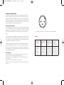
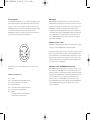
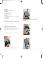
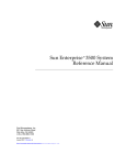
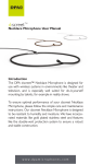
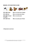
MANUAL DPIHMA5000
26/08/04
11:12
Side 1
USER’S MANUAL
Two-Channel Hi-Voltage Microphone Amplifier
Type
HMA5000
CONTENTS
Technical Description
Technical Specifications
Changing the Mains Fuse in HMA5000
Care of HMA5000
Important Safety Instructions
Service and Repair
Warranty
CE Marking
2
7
8
10
11
12
12
12
1
MANUAL DPIHMA5000
26/08/04
11:12
Side 2
TECHNICAL DESCRIPTION
The DPA High-Voltage microphones types: 4003, 4004, 4012, 4016,
4041-S, and 4041-T are powered via the Two-Channel High-Voltage
Microphone Amplifier HMA5000, which supplies 130 V to their built-in
preamplifiers giving the microphones excellent SPL handling capability. But the HMA5000 is not only a power supply unit, it is also a microphone amplifier with outstanding specifications.
1
2
3
The Microphone Amplifier
The HMA5000 uses state-of-the-art, low-noise operational amplifiers
from Analog Devices‚ in the input stages. Each channel input features
independently switchable gain by +30 dB, +20 dB, +10 dB, 0 dB, -10 dB
or -20 dB corresponding to a maximum input voltage of 0.5 -160 V
peak.
The signal path in the HMA5000 is completely transformerless, which
gives the microphone amplifier an excellent frequency range from 10
Hz to 100 kHz (-1 dB). The HMA5000 has a Crosstalk attenuation better
than 90 dB measured with any gain setting.
Featuring both electronically balanced and single ended line-level outputs, the HMA5000’s impedance converters can drive up to 300 m
(984 ft) of microphone cable. Both input channels are single ended
and it is required to use the dedicated DPA Microphone cables in order
to optimize noise rejection.
Polarity Switch
A polarity switch for each channel is found on the rear next to the
output connector of the corresponding line output.
In the position "0°" the HMA5000 system has absolute phase from
input to output.
Switching to "Inv." (Inverse) will invert the phase.
(See Fig. 1 and Fig. 2 for pin designation of the output and input connectors).
2
Fig. 1. External view of the output connector of the HMA5000.
Polarity
Positive going
- produces this elec-
When switch in 0°-
When switch in
sound pressure on
trical signal on the
position then
"Inv."-position,
microhone type:
HMA5000 input
HMA5000 output
HMA5000
pin 4:
on pin 2 is:
output on pin 2 is:
DPA 4003
DPA 4004
DPA 4012
DPA 4016
DPA 4041-S
DPA 4041-T
positive going
positive going
positive going
positive going
negative going
negative going
positive going
positive going
positive going
positive going
negative going
negative going
negative going
negative going
negative going
negative going
positive going
positive going
3
MANUAL DPIHMA5000
26/08/04
11:12
Side 4
The Power Supplies
Mains Supply
The HMA5000 supplies 130 V DC to the built-in preamplifiers of the
High-Voltage Microphones Types 4003, 4004, 4012, 4016, 4041-S,
and 4041-T via pin 2 on the modified 7-pin input connector on the
HMA5000, giving the microphones an extended SPL handling capability
compared to P48 powered microphones. Furthermore, the
HMA5000 has 190 V DC on pin 5 for polarisation voltage and 6.3 V
DC on pin 6 for tube heating (re pin 3). See Fig. 2.
The HMA5000 can be operated from either 120 V/60 Hz or 230
V/50 Hz external powering, and automatically switches to the appropriate power setting when connected. The AC mains supply for the
HMA5000 is connected via the 3-pin IEC 320 connector, which
accepts the mains cable supplied. Maximum power consumption is
15 W. Please take care that the HMA5000 is properly grounded. The
mains fuse needs only to be checked if the power indicator on the
front of the HMA5000 fails to light. See the chapter ‘Changing the
Mains Fuse in HMA5000’.
Optional accessories - Cables
Special high-voltage microphone cables can be obtained as an optional
accessory for the HMA5000 (see Accessories Available)
6
5
1
7
4
3
2
Fig. 2. External view of the modified 7-pin input connector of the
HMA5000.
Modified 7-pin XLR pinouts:
Pin 1:
Pin 2:
Pin 3:
Pin 4:
Pin 5:
Pin 6:
Pin 7:
4
Ground
+130 V Microphone Preamplifier Voltage
Heater return (65 V DC potential)
Microphone input
+190 V Microphone cartridge polarisation
+6.3 V Heater Voltage (Re pin 3)
Blinded
All voltages measured with reference to
ground unless otherwise stated
The DPA microphone cables consist of oxygen free copper strands in
both conductors and shield. The tightly woven shield has 98% coverage and therefore has an extremely efficient noise rejection. Custom
lengths of high-voltage microphone cable up to 20 m (66 ft) can be
ordered. Please contact your local DPA Microphones representative
if you require custom cable lengths.
Optional accessories - HTP4000 Phantom Converter
The HTP4000 High-Voltage to Phantom Converter connects to the
input socket of the HMA5000 and converts the high-voltage microphone input channel to a P48 microphone input channel of extremely
high quality. The HTP4000 uses a standard 3-pin female XLR-connector on the audio input, and a modified 7-pin male XLR-connector
where it connects to the HMA5000. Using standard DPA microphones 4006, 4007, 4011, 4015 or 4041-SP with the HMA5000 and
the HTP4000, the absolute phase is preserved with the output
switch in position 0°.
5
MANUAL DPIHMA5000
26/08/04
11:12
Side 6
Gain:
+30 dB, +20 dB, +10 dB, 0 dB, -10 dB, -20 dB (±0.5 dB)
For use with:
Standard Microphones
3529-A A-B Stereo Kit, 130 V
3532-S Large Diaphragm A-B Stereo Kit, Solid State, 130 V
3532-T Large Diaphragm A-B Stereo Kit, Tube, 130 V
4003
Omnidirectional Microphone, 130 V
4004
Hi-SPL Omnidirectional Microphone, 130 V
4012
Cardioid Microphone, 130 V
4016
Wide Cardioid Microphone, 130 V
4041-S Omnidirectional Solid State Microphone
4041-T Omnidirectional Tube Microphone
Equivalent input noise level A-weighted Pin 1-2 and pin 1-3
Gain setting -20 dB
-10 dB
0 dB
10 dB
20 dB
30 dB
Eqv inp noise -92 dBu -99 dBu -115 dBu -123 dBu -128 dBu -129 dBu
Equivalent input noise level ITU-RBS.468-4 Pin 1-2 and pin 1-3
Gain setting -20 dB
-10 dB
0 dB
10 dB
20 dB
30 dB
Eqv inp noise -82 dBu -89 dBu -105 dBu -113 dBu -118 dBu 1
- 19 dBu
The "balanced" noise measured between pin 2 –3 is 3 dB higher than
the value stated in the tables
Accessories Included:
Mains Cable
250 mA Slow Blow Fuse
Accessories Available:
Connection Adapters
HTP4000 Converter: 130 V to P48
Cables for DPA4003/04/12/16:
DAO0130 130 V Microphone Cable, 5 m (16.4 ft)
DAO0131 130 V Microphone Cable, 10 m (32.8 ft)
Cables for DPA4041-S/T:
DAO4110 130 V Microphone Cable,10 m (32.8 ft)
TECHNICAL SPECIFICATIONS
Dimensions (l x w x h):
200 x 133 x 52 mm (7.87 x 5.24 x 2.05 in)
Weight:
1.85 kg/4.08 lb
Frequency Range:
10 Hz to 100 kHz +0 dB / -1 dB (Resistive Load)
Dynamic Range:
> 120 dB
No of channels:
2
Crosstalk attenuation:
>90 dB (20 Hz to 20 kHz) (No Load) (Vo = 10 V)
6
Cable drive capability:
up to 300 m (984 ft) (Cable 100 pF/m)
Max input peak voltage:
0.5 V (+30 dB); 1.6 V (+20 dB); 5 V (+10 dB); 16 V (0 dB); 50 V
(-10 dB); 160 V (-20 dB)
Max output peak voltage:
32 V peak (15 V for single ended operation)
Input impedance:
30 kOhm (with HTP4000: 5 kOhm)
Output impedance:
40 Ohm each output (80 Ohm balanced)
Total Harmonic Distortion (THD) in %
Output
voltage
30 Hz 100 Hz 300 Hz 1 kHz
Vo = 10 V
Vo = 3 V
Vo = 1 V
0.006
0.006
0.010
0.007
0.007
0.01
0.004
0.005
0.008
0.004
0.004
0.008
3 kHz
10 kHz 30 kHz
0.004
0.004
0.008
0.004
0.005
0.008
0.004
0.005
0.009
Max output current:
2 x 55 mA
Max output DC offset:
±20 mV
Min load impedance:
600 Ohm
7
MANUAL DPIHMA5000
26/08/04
11:12
Side 8
Input connector:
Modified 7-pin female XLR-connector
Output connector:
Standard 3-pin male XLR-connector
Operating temperature range:
-10° C to +55° C (+14 to 131° F)
Mains voltage: 1
00 VAC – 127 VAC and 200 VAC – 240 VAC, 50 Hz and 60 Hz
Power consumption:
Maximum 15 W
Note:
The specifications and tolerances listed, as well as performance and
stability of the HMA5000, are only guaranteed when using the dedicated cables from DPA Microphones.
2. Unscrew the two retaining screws on the metal casing of the
HMA5000
CHANGING THE MAINS FUSE IN HMA5000
The HMA5000 is protected with a 250 mA slow blow fuse.
The fuse is rated to give adequate protection at both 120 VAC and
230 VAC. Only the correct replacement fuse must be fitted.
WARNING! Disconnect the HMA5000 from the mains supply before
removing the instrument housing.
3. Gently pull out the assembly.
1. The mains fuse holder is located on the printed circuit board of the
HMA5000. To gain access, the front and rear face panels of the
HMA5000 should be removed by pulling the top and bottom bezels
off the clip on frame outwards (as shown).
8
4. Remove the Mains Fuse with a screwdriver and insert a new Mains
Fuse likewise.
9
MANUAL DPIHMA5000
26/08/04
11:12
Side 10
CARE OF THE HMA5000
IMPORTANT SAFETY INSTRUCTIONS
The operating temperature range of Type HMA5000 Two-Channel
High-Voltage Microphone Amplifier is from -10° C to +55° C (+14° F to
+131° F).
Do´s and Don’t´s
The HMA5000 is protected against internal overheating by a thermal
fuse which operates at 125° C ±5° C.
The HMA5000 is extremely ruggedized. It is insensitive to vibration
and will withstand mechanical shock. Therefore the HMA5000 is well
suited for placement on the stage or the studio floor.
To reduce the risk of hum, please observe that the HMA5000 and
the connected equipment are connected to the same mains phase.
Please read all instructions and precautions carefully before using
your DPA Microphones product.
1. Do ALWAYS disconnect your equipment from AC mains before
connecting / disconnecting any cables, or when cleaning any product.
2. This DPA Microphones product must be terminated with a AC
mains power cord which includes an earth ground conductor. To
prevent shock hazard, it must be connected to safety ground.
3. Do stop operating your equipment if you discover any defects in
materials, AC mains power cords, etc.
4. Do not operate this DPA Microphones product with any covers
removed.
5. Do not use flammable or combustible chemicals for cleaning
your DPA Microphones product.
6. Do not pour or spill liquids directly onto your DPA Microphones
product.
7. Do not replace any fuse / fuses with a value or type other than
those specified to prevent electrical and / or fire hazard.
8. Do not expose this DPA product to high humidity and extremely
high or low temperatures.
9. Do not operate this DPA product in an explosive atmosphere
10. Do not attempt to repair your DPA product yourself. If a problem
occurs, contact your nearest DPA Microphones representative.
11. Do ALWAYS ensure sufficient air flow when operating this DPA
Microphones product.
12. Do ALWAYS keep electrical equipment out of reach of children.
13. Do ALWAYS unplug sensitive electronic equipment during light
ning storms.
10
11
MANUAL DPIHMA5000
26/08/04
11:12
Side 12
SERVICE & REPAIR
Products from DPA Microphones are extremely stable, and there
should not be any significant change in the specifications with time
and use. If, however, you are not totally satisfied with the characteristics exhibited by these products, contact your nearest DPA Microphones
representative for further details of service and the repair facilities
that are available. DPA Microphones has a maximum seven working
days in-house service policy, usually ensuring that no more than
seven working days will elapse from the day we receive the item for
service to the day we are ready to return it to you. Please contact
DPA Microphones for your nearest representative on
TEL: + 45 48 14 28 28
FAX: + 45 48 14 27 00
You can also get in touch with DPA Microphones via the internet
using e-mail [email protected] or visit our website at
www.dpamicrophones.com
WARRANTY
All products from DPA Microphones are covered by a two-year limited warranty on both mechanical functionality and documented specifications as long as the items are not mistreated, abused or modified
in any way. In case of a warranty claim your invoice is your warranty
registration.
CE MARKING
The CE-mark guarantees that the product conforms with relevant
Directives approved by the European Commission.
EMC Directive: 89/336/C, amended by 92/31/EC and 93/68/EC
Low Voltage Directive: 73/23/EC, amended by 93/68/EC.
Product features and specifications are subject to change without notice.
12