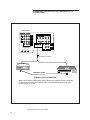
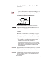
1
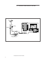
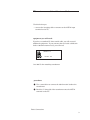
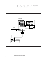
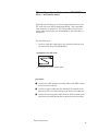
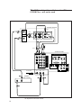
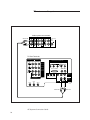
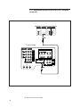
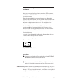
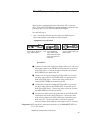
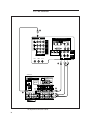
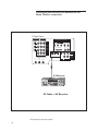
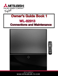
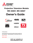
VS-50803
VS-60803
WS-65903
VS-70803
WS-73903
VS-80803
AV Systems Connections Guide
VIDEO
S-VIDEO
AUDIO
V
HIGH-DEFINITION INTERFACE
L (MONO) R
HDTV VIDEO
R
INPUT-1
G
B
H
V
INPUT-2
HDTV CONTROL
HDTV AUDIO
L (MONO)
R
INPUT-3
MONITOR
OUTPUT
Y
Cr
Cb
DVD VIDEO
IR
HOME
THEATER
ACTIVE A/V
IR/
G LINK NETWORK
V
L (MONO) R
L (MONO) R
ANT-A
LOOP
OUT
VIDEO
PIP
AUDIO
OUTPUT
AUDIO
ANT-B
1
CAUTION
RISK OF ELECTRIC SHOCK
DO NOT OPEN
CAUTION: TO REDUCE THE RISK OF ELECTRIC SHOCK,
DO NOT REMOVE COVER (OR BACK).
NO USER-SERVICEABLE PARTS INSIDE.
REFER SERVICING TO QUALIFIED SERVICE PERSONNEL
The lightning flash with arrowhead symbol within an equilateral
triangle is intended to alert the user to the presence of uninsulated
“dangerous voltage” within the product’s enclosure that may be of
sufficient magnitude to constitute a risk of electric shock.
The exclamation point within an equilateral triangle is intended to
alert the user to the presence of important operating and
maintenance (servicing) instructions in the literature accompanying
the appliance.
æWarning: Don’t leave stationary images, such as stock market
reports, video games, station logos, or the TV’s displays, on-screen for
more than 10 minutes. Still patterns and repeated display of the same
pattern can scar the picture tube, causing permanent damage to the TV.
WARNING:
TO REDUCE THE RISK OF FIRE OR ELECTRIC SHOCK, DO NOT EXPOSE THIS APPLIANCE TO RAIN OR MOISTURE
CAUTION:
TO PREVENT ELECTRIC SHOCK HAZARD, DO NOT USE THIS UNIT'S (POLARIZED) PLUG
WITH AN EXTENSION CORD, RECEPTACLE OR OTHER OUTLET UNLESS THE BLADES
CAN BE FULLY INSERTED TO PREVENT BLADE EXPOSURE.
NOTE TO CATV SYSTEM INSTALLER:
THIS REMINDER IS PROVIDED TO CALL THE CATV SYSTEM INSTALLER’S ATTENTION
TO ARTICLE 820-40 OF THE NEC THAT PROVIDES GUIDELINES FOR PROPER
GROUNDING AND, IN PARTICULAR, SPECIFIES THAT THE CABLE GROUND SHALL BE
CONNECTED TO THE GROUNDING SYSTEM OF THE BUILDING, AS CLOSE TO THE
POINT OF CABLE ENTRY AS PRACTICAL.
AV Systems Connection Guide
2
MITSUBISHI
Connections
Table of Contents
Chapter 1: Basic Connections ............................................ 5
TV + separate UHF and VHF antennas ................................... 6
TV + antenna or cable without a cable box .............................. 8
TV + cable with a cable box when TV Guide Plus +
will not be used ........................................................................ 10
TV + VCR + cable with a cable box when TV Guide Plus +
will not be used ........................................................................ 12
TV + VCR + antenna or cable without a cable box................. 14
Connecting the Infrared (IR) Emitter ..................................... 16
TV + cable with a cable box when TV Guide Plus +
will be used ............................................................................... 18
TV + VCR + cable with a cable box when TV Guide Plus +
will be used ............................................................................... 20
Chapter 2: Additional Component Connections ............... 23
TV + stereo audio system ........................................................ 24
TV + Mitsubishi products that have A/V network terminals 26
TV + DVD player with Component Video Outputs ................ 28
TV + AV receiver ...................................................................... 30
TV + HDTV receiver (Mitsubishi brand only) and cable ....... 34
3
blank page
AV Systems Connection Guide
4
CHAPTER
ONE
Basic Connections
This section will show you the basic connections to hookup your TV.
If you have difficulty making any of the connections to your TV, you
may want to contact your Mitsubishi dealer or your local cable
company.
• TV + separate UHF and VHF antennas
• TV + antenna or cable without a cable box
• TV + cable with a cable box without TV GUIDE Plus+
• TV + VCR + cable with a cable box without TV GUIDE
Plus+
• TV + VCR + antenna or cable without a cable box
• Connecting the Infrared (IR) Emitter
• TV + cable with a cable box with TV GUIDE Plus+
• TV + VCR + cable with a cable box with TV GUIDE Plus+
æWarning: You should unplug your TV and any other components before
connecting them.
5
TV + separate UHF and VHF antennas
VHF Antenna
(Channels 2-13)
Flat Twin Lead
UHF Antenna
(Channels 14-69)
Flat Twin Lead
TV Rear Terminal
External
Antenna
or Cable
VIDEO
S-VIDEO
AUDIO
V
HIGH-DEFINITION INTERFACE
L (MONO) R
HDTV VIDEO
R
INPUT-1
G
B
H
V
INPUT-2
HDTV CONTROL
HDTV AUDIO
L (MONO)
R
INPUT-3
MONITOR
OUTPUT
Y
300 Ohm to
75 Ohm
Combiner
UHF
Cr
DVD VIDEO
¢
ANT-A
LOOP
OUT
VHF
Side
AV Systems Connection Guide
6
IR
HOME
THEATER
ACTIVE A/V
IR/
G LINK NETWORK
V
L (MONO) R
L (MONO) R
†
Back
Cb
VIDEO
ANT-B
AUDIO
PIP
AUDIO
OUTPUT
TV + separate UHF and VHF antennas
If UHF and VHF signals are brought into your home with two
separate antennas, you’ll need to combine them in order to connect
them to the TV. To do this you will need a UHF/VHF combiner.
Use this hook-up to:
• connect separate UHF and VHF antennas to your TV.
equipment you will need:
X
X
UHF
75 OHM Out
300 OHM
X
X
VHF
This is a standard combiner with the following specifications:
Two (2) 300 ohm inputs
One (1) 75 ohm output
(There are different combiners for different kinds of wires. Check
with your local electronics store for the kind of combiner you need.)
procedure:
† Connect the UHF and VHF antenna leads to the appropriate
terminals on the UHF/VHF combiner.
¢ Press the combiner onto the ANT-A terminal on the rear of the
TV.
Basic Connections
7
TV + antenna or cable without a cable box
TV rear terminals
VIDEO
S-VIDEO
AUDIO
V
HIGH-DEFINITION INTERFACE
L (MONO) R
HDTV VIDEO
R
INPUT-1
75 Ohm
Coaxial Cable
G
B
H
V
INPUT-2
HDTV CONTROL
300 Ohm Flat
Twin Lead
HDTV AUDIO
L (MONO)
R
INPUT-3
MONITOR
OUTPUT
Y
Cr
Cb
DVD VIDEO
IR
HOME
THEATER
ACTIVE A/V
IR/
G LINK NETWORK
V
L (MONO) R
L (MONO) R
†
¢
ANT-A
LOOP
OUT
Optional 300 Ohm to 75 Ohm
Matching Transformer
AV Systems Connection Guide
8
VIDEO
ANT-B
AUDIO
PIP
AUDIO
OUTPUT
TV + antenna or cable without a cable box
Use this hook-up to:
• connect the incoming cable or antenna to the ANT-A input
terminal on the TV.
equipment you will need:
If you have a standard 75-ohm coaxial cable, you will not need
additional equipment. If your antenna has two leads (called twin
lead or 300 ohm antenna lead), you will need:
300 ohm - in
75 ohm - out
One 300-75 ohm matching transformer
procedure:
† Use a screwdriver to connect the 300 ohm twin leads to the
transformer.
¢ Push the 75 ohm side of the transformer onto the ANT-A
terminal on the TV.
Basic Connections
9
TV + cable with a cable box when TV GUIDE
Plus + will not be used
TV rear terminals
VIDEO
S-VIDEO
AUDIO
V
HIGH-DEFINITION INTERFACE
L (MONO) R
HDTV VIDEO
R
INPUT-1
G
B
H
V
INPUT-2
HDTV CONTROL
HDTV AUDIO
L (MONO)
R
INPUT-3
MONITOR
OUTPUT
Y
Cr
IR
HOME
THEATER
Cb
DVD VIDEO
Incoming
Cable †
£
IN
ANT-A
LOOP
OUT
VIDEO
ANT-B
£
Cable Box
rear terminals
OUT
AV Systems Connection Guide
10
V
L (MONO) R
L (MONO) R
¢
¢
ACTIVE A/V
IR/
G LINK NETWORK
AUDIO
PIP
AUDIO
OUTPUT
TV + cable with a cable box when TV GUIDE
Plus + will not be used
This hook-up will allow you to use the advanced features of your
TV, such as 2-tuner PIP and SuperQuickView™ and watch basic
cable channels on Antenna-A. You will be able to view the premium cable channels that are descrambled by your cable box on
Antenna-B.
Use this hook-up to:
• connect a cable box used only to view premium channels and
you will not be using TV GUIDE Plus +
equipment you will need:
two lengths of 75 ohm coaxial cable
procedure
† Connect the cable system’s incoming cable to the ANT-A terminal on the back of the TV.
¢ Connect a coaxial cable from the LOOP-OUT terminal on the
back of the TV to the IN terminal on the back of the cable box.
£ Connect the second coaxial cable from the OUT terminal of the
cable box to the ANT-B terminal on the back of the television.
Basic Connections
11
TV + VCR + cable with a cable box when TV
GUIDE Plus + will not be used
VCR Rear Terminals
Yellow
£
L
Antenna
§
®
L
(Y/C)
CH-1
CH-1
2
1
Red
VIDEO OUT
AUDIO IN
AUDIO OUT
White
IN
©
1
MONITOR
R
R
CH-2
CH-2
OUT
Attach
only
one
cable
type
W
h
i
t
e
R
e
d
Yellow
§
©
TV Rear Terminals
VIDEO
AUDIO
S-VIDEO
V
HIGH-DEFINITION INTERFACE
L (MONO) R
HDTV VIDEO
R
INPUT-1
G
B
H
V
INPUT-2
HDTV CONTROL
HDTV AUDIO
L (MONO)
R
INPUT-3
MONITOR
OUTPUT
Y
Cr
IR
HOME
THEATER
Cb
DVD VIDEO
ACTIVE A/V
IR/
G LINK NETWORK
V
L (MONO) R
L (MONO) R
Incoming Cable
ANT-A
LOOP
OUT
VIDEO
ANT-B
†
£
Cable Box
Rear Terminals
¢
OUT
IN
¢
AV Systems Connection Guide
12
®
AUDIO
PIP
AUDIO
OUTPUT
TV + VCR + cable with a cable box when TV
GUIDE Plus + will not be used
Use this hook-up to:
• connect a VCR along with your cable and cable box, when you
will not be using TV GUIDE Plus+
equipment you will need:
R
R
LL
L
L
R
R
Three lengths of
75 ohm coaxial cable
One set of RCA pintype audio cables
One RCA pin-type
video cable (if connecting a standard VCR)
One S-Video cable
(if connecting a
S-VHS VCR)
procedure:
† Connect the incoming cable to the ANT-A terminal on back of
the TV.
¢ Connect a coaxial cable from the LOOP-OUT terminal on the
back of the TV to the cable box IN terminal.
£ Connect a second cable from the OUT terminal on the cable box
to the ANTENNA IN terminal on the back of the VCR.
® Connect a third coaxial cable from the ANTENNA OUT terminal on the back of the VCR to the ANT-B terminal on the back
of the TV.
© Connect an RCA pin-type video cable from the VIDEO OUT
terminal on the back of the VCR to the VIDEO INPUT 1 or
INPUT 2 terminal on the back of the TV.
⁄Important: If you are connecting a Super VHS (S-VHS) VCR, use an S-Video
cable instead of an RCA pin-type video cable. Connect this cable to
the S-VIDEO OUT terminal on the VCR. Connect the other end of
this cable to the S-VIDEO INPUT 1 or INPUT 2 terminal on the
back of the TV.
§ Connect a set of RCA pin-type audio cables to the AUDIO OUT
terminals on the back of the VCR. Use the red cable to connect
the right (R) channel and the white cable to connect the left (L)
channel. Connect the other ends of this cable to the AUDIO
INPUT terminals on the back of the TV.
⁄Important: If your VCR is monaural (non-stereo), connect a single RCA pintype audio cable. Connect the cable from the VCR's AUDIO OUT
terminal to the left (L) AUDIO INPUT on the back of the TV.
⁄Important: If your VCR has a video channel switch with an “OFF” position, set
it to “OFF”. See your VCR owner’s guide for details.
Basic Connections
13
TV + VCR + antenna or cable without a cable box
VCR Rear Terminals
Yellow
¢
IN
White
L
L
CH-1
Antenna
CH-1
2
1
Red
£
VIDEO OUT
AUDIO IN
AUDIO OUT
©
(Y/C)
®
1
MONITOR
R
R
CH-2
CH-2
OUT
Attach
only
one
cable
type
W
h
i
t
e
®
R
e
d
©
Yellow
TV Rear Terminals
VIDEO
S-VIDEO
AUDIO
V
HIGH-DEFINITION INTERFACE
L (MONO) R
HDTV VIDEO
R
INPUT-1
G
B
H
V
INPUT-2
HDTV CONTROL
HDTV AUDIO
L (MONO)
R
INPUT-3
MONITOR
OUTPUT
Y
Cr
Cb
DVD VIDEO
IR
HOME
THEATER
ACTIVE A/V
IR/
G LINK NETWORK
V
L (MONO) R
L
Incoming Cable
ANT-A
LOOP
OUT
VIDEO
R
AUDIO
ANT-B
§
†
IR Emitter
¢
£
AV Systems Connection Guide
14
(MONO)
TV Guide Plus +
PIP
AUDIO
OUTPUT
TV + VCR + antenna or cable without a cable box
Use this hook-up to:
• connect a VCR along with your cable or antenna
equipment you will need:
R
L
L
R
Two lengths of
75 ohm coaxial
cable
One set of RCA
pin-type audio
cable
One IR emitter
assembly (if
connecting TV
Guide Plus +
One RCA pin- OR One S-Video cable
type video
(if connecting
cable
a S-VHS VCR)
procedure
† Connect the incoming cable to the ANT-A terminal on back of
the TV.
¢ Connect one end of the coaxial cable from the LOOP-OUT
terminal on the TV to the ANTENNA IN terminal on the VCR.
£ Connect the second coaxial cable from the VCR ANTENNA
OUT to the TV ANT-B.
® Connect an RCA pin-type video cable from the VIDEO OUT
terminal on the back of the VCR to the VIDEO INPUT 1 or
INPUT 2 terminal on the back of the television.
⁄Important:
If you are connecting a Super VHS (S-VHS) VCR, use an S-Video
cable instead of an RCA pin-type video cable. Connect this S-Video
cable from the S-VIDEO OUT terminal on the VCR to the SVIDEO INPUT 1 or INPUT 2 terminal on the back of the TV.
© Connect a set of RCA pin-type audio cables to the AUDIO OUT
terminals on the back of the VCR. Use the red cable to connect
the right (R) channel and the white cable for connecting the left
(L) channel. Connect the other ends of this cable to the AUDIO
INPUT terminals on the back of the TV.
⁄Important:
If your VCR is monaural (non-stereo), connect a single RCA pintype audio cable. Connect the cable from the VCR's AUDIO OUT
terminal to the left (L) AUDIO INPUT on the back of the TV.
§ If you plan to use TV GUIDE Plus+, connect the IR emitter
cable to the IR /G LINK jack. Place one of the emitter ends in
front of the VCR. For more detail concerning the placement of
the emitter lenses, see pages 16 and 17 of this book.
⁄Important:
If your VCR has a video channel switch with an “OFF” position, set
it to “OFF”. See your VCR owner’s guide for details.
Basic Connections
15
Connecting the Infrared (IR) Emitter for TV
GUIDE Plus+
TV Back Panel
VIDEO
S-VIDEO
AUDIO
V
HIGH-DEFINITION INTERFACE
L (MONO) R
HDTV VIDEO
R
INPUT-1
G
B
H
V
INPUT-2
HDTV CONTROL
HDTV AUDIO
L (MONO)
R
INPUT-3
MONITOR
OUTPUT
Y
Cr
Cb
DVD VIDEO
IR
HOME
THEATER
IR/
G LINK
ACTIVE A/V
NETWORK
V
L (MONO)
R
L (MONO) R
ANT-A
LOOP
OUT
VIDEO
PIP
AUDIO
OUTPUT
AUDIO
ANT-B
IR Emitter Connector
Cable Box
VCR
Channel Choice
IR Emitter Set Up
Adhesive Foam Tape*
IR Cable + VCR + Cable Box
*NOTE: When permanent attachment is desired, determine the best point for each IR transmitter.
Fix one side of the adhesive tape to the flat bottom of the transmitter and the other side to the
anchoring object you choose.
AV Systems Connection Guide
16
Connecting the Infrared (IR) Emitter for TV
GUIDE Plus+
Use this hook-up to:
• use TV GUIDE Plus+ with a cable box and/or VCR. There are
two separate IR emitters connected to the end of the plug. Each
IR emitter is used to send control signals from your TV to your
cable box, and/or your VCR.
equipment you will need (included with TV):
Transmitter Lenses
IR Emitter
IR emitter assembly
two strips of double-sided adhesive foam tape (not pictured).
Important: The IR emitter included with your TV must be connected to the
⁄Important:
back panel of the TV before cable box and VCR users can perform
the initial set up of TV GUIDE Plus+.
procedure
† Insert the IR emitter into the IR / G LINK jack at the back of
your TV as shown in the illustration on the previous page.
¢ Arrange each cable line coming from an IR emitter so that it
can be laid underneath or along side of the cable box or VCR.
£ Place each IR transmitter lens (small clear sphere resembling a
tiny light bulb) so that it directly faces the remote control
infrared receiver(s) of your cable box and/or VCR.
Infrared receivers are usually located on the front face of the
VCR or cable box. Consult the owner manual(s) of your equipment to ensure accurate positioning of the Mitsubishi IR
transmitter lenses.
⁄Important: When you have both a cable box and a VCR, place one IR transmitter in front of each component. When you have only a cable box or
a VCR, but not both, place one IR transmitter in front of that
component and place the other IR transmitter in another, out-ofthe-way location.
⁄Important: TV GUIDE Plus+ can control only those types of cable boxes and
VCRs that can select channels by using the number keypad on
their remote controls.
Basic Connections
17
TV + cable with a cable box when TV GUIDE Plus
+ will be used
Incoming
Cable
†
TV Rear Terminal
VIDEO
AUDIO
HIGH-DEFINITION INTERFACE
IN
S-VIDEO
OUT
V
L (MONO) R
HDTV VIDEO
OUT
R
INPUT-1
G
B
H
V
INPUT-2
HDTV CONTROL
£
¢
HDTV AUDIO
L (MONO)
R
INPUT-3
MONITOR
OUTPUT
Y
Cr
Cb
DVD VIDEO
IR
HOME
THEATER
ACTIVE A/V
IR/
G LINK NETWORK
V
L (MONO) R
L (MONO) R
ANT-A
LOOP
OUT
VIDEO
ANT-B
©
®
IR Emitter
¢
£
®
Cable Box
Rear Terminal
IN
OUT
AV Systems Connection Guide
18
AUDIO
PIP
AUDIO
OUTPUT
TV + cable with a cable box when TV GUIDE Plus
+ will be used
Use this hook-up to:
• connect a cable box to view premium cable channels and use
TV GUIDE Plus+
equipment you will need:
IN
OUT
Transmitter Lenses
OUT
IR Emitter
one two-way splitter
four lengths of 75 ohm
coaxial cable
one IR emitter assembly
(provided with TV)
procedure:
† Connect the cable system’s incoming cable to the IN terminal
on the two-way splitter. NOTE: This splitter must be a type
approved by your local cable provider.
¢ Connect one coaxial cable from one of the OUT terminals on the
splitter to the ANT-B terminal on the back of the TV.
£ Connect a second coaxial cable from the other OUT terminal on
the splitter to the IN terminal on the cable box.
® Connect the third coaxial cable from the OUT terminal on the
back of the cable box to the ANT-A terminal on the back of the
TV.
© Connect the IR emitter to the IR/G LINK. Place one of the
emitter ends in front of the cable box. For more detail concerning the placement of the transmitter lenses, see pages 16 and
17 of this book.
⁄Important: TV GUIDE Plus+ can control only those types of cable boxes and
VCRs that can select channels by using the number keypad on
their remote controls.
Basic Connections
19
TV + VCR + cable with a cable box when TV
GUIDE Plus + will be used
VCR Rear Terminals
Yellow
©
L
¶
Antenna
CH-1
1
Red
VIDEO OUT
AUDIO IN
AUDIO OUT
White
IN
L
(Y/C)
CH-1
2
§
1
MONITOR
R
R
CH-2
CH-2
OUT
Attach
only
one
cable
type
Yellow
W
h
i
t
e
R
e
d
§
¶
TV Rear Terminals
VIDEO
S-VIDEO
AUDIO
V
HIGH-DEFINITION INTERFACE
L (MONO) R
HDTV VIDEO
R
INPUT-1
B
G
H
V
INPUT-2
HDTV CONTROL
HDTV AUDIO
L (MONO)
R
INPUT-3
MONITOR
OUTPUT
Y
©
Cr
IR
HOME
THEATER
Cb
DVD VIDEO
ACTIVE A/V
IR/
G LINK NETWORK
V
L (MONO) R
L (MONO) R
ANT-A
LOOP
OUT
VIDEO
ANT-B
|
®
¢
IR Emitter
®
Cable Box
Rear Terminals
£
OUT
IN
Two Way
Splitter
£
†
OUT
IN
OUT
Incoming Cable
¢
AV Systems Connection Guide
20
AUDIO
PIP
AUDIO
OUTPUT
TV + VCR + cable with a cable box when TV
GUIDE Plus + will be used
Use this hook-up to:
• connect a VCR along with a cable box and use TV GUIDE Plus+
equipment you will need:
IR Transmitters
IN
Transmitter Lenses
OUT
OUT
IR Emitter Connection
one two-way splitter
four lengths of 75 ohm coaxial cable
one IR emitter
(provided with TV)
R
L
L
R
one set of RCA pintype audio cables
One RCA pin-type
video cable
One S-Video cable
(if connecting a S-VHS
VCR)
⁄Important TV GUIDE Plus+ can control only those types of cable boxes and
VCRs that can select channels by using the number keypad on their
remote controls.
procedure
† Connect the cable system’s incoming cable to the IN terminal
on the two-way splitter.
¢ Connect a coaxial cable to one of the OUT terminals on the
splitter; connect the other end of this cable to the ANT-B
terminal on the back of the TV.
£ Connect a second coaxial cable to the other OUT terminal on
the splitter; connect the other end of this cable to the IN terminal on the cable box.
® Connect the third coaxial cable to the OUT terminal on the
back of the cable box; connect the other end of this cable to the
ANT-A terminal on the back of the TV.
© Connect the fourth coaxial cable from the CABLE LOOP-OUT
terminal on the back of the TV to the ANTENNA IN terminal
on the back of the VCR.
Basic Connections
21
TV + cable with a cable box with TV GUIDE Plus +
(cont.)
§ Connect an RCA pin-type video cable from the VIDEO OUT
terminal on the back of the VCR to the VIDEO INPUT 1 or
INPUT 2 terminal on the back of the TV.
⁄Important: If you are connecting a Super VHS (S-VHS) VCR, use an S-Video
cable instead of an RCA pin-type video cable. Connect this S-Video
cable to the S-VIDEO OUT terminal on the VCR. Connect the
other end of this cable to the S-VIDEO INPUT 1 or INPUT 2
terminal on the back of the TV.
¶ Connect a set of RCA pin-type audio cables to the AUDIO OUT
terminals on the back of the VCR. Use the red cable to connect
the right (R) channel and the white cable to connect the left (L)
channel. Connect the other ends of this cable to the AUDIO
INPUT terminals on the back of the TV.
⁄Important: If your VCR is monaural (non-stereo), connect a single RCA pintype audio cable. Connect the cable from the VCR's AUDIO OUT
terminal to the left (L) AUDIO INPUT on the back of the TV.
| Connect the IR emitter cable to the IR OUT /G LINK. Place
one of the emitter ends in front of the cable box. Place the
other emitter end in front of the VCR. For more detail concerning the placement of the emitter lenses, see pages 16 and 17 of
this book.
⁄Important: If your VCR has a video channel switch with an “OFF” position, set
it to “OFF”. See your VCR owner’s guide for details
.
AV Systems Connection Guide
22
CHAPTER
TWO
Additional Component Connections
This book will show you the basic connections to hookup your TV
with components.
If you have difficulty making any of the connections to your TV, you
may want to contact your Mitsubishi dealer or your local cable
company.
• TV + stereo audio system
• TV + Mitsubishi products that have A/V Network
terminals
• TV + DVD player with Component Video Outputs
• TV + AV receiver
• TV + HDTV receiver (Mitsubishi brand only) and cable
æWarning: You should unplug your TV and any other components before
connecting them.
23
TV + stereo audio system
Audio system rear terminals
CD
IN
White Lead
AUX
IN
IN
TAPE 1
OUT
IN
TAPE 2
OUT
SUBWOOFER
OUT
(MONO)
L
†
R
Red Lead
TV Rear Terminals
VIDEO
S-VIDEO
AUDIO
V
HIGH-DEFINITION INTERFACE
L (MONO) R
HDTV VIDEO
R
INPUT-1
G
B
H
V
INPUT-2
HDTV CONTROL
HDTV AUDIO
L (MONO)
R
INPUT-3
MONITOR
OUTPUT
Y
Cr
Cb
DVD VIDEO
IR
HOME
THEATER
ACTIVE A/V
IR/
G LINK NETWORK
V
L (MONO) R
L (MONO)
ANT-A
LOOP
OUT
VIDEO
PIP
AUDIO
OUTPUT
AUDIO
ANT-B
White Lead
AV Systems Connection Guide
24
R
†
Red Lead
TV + stereo audio system
After you have completed your basic connections (TV to antenna,
cable, VCR and TV GUIDE Plus+ emitter assembly) as shown in
the previous pages,
Use this hook-up to:
• listen to the sound from your TV and/or VCR through your
home audio system.
equipment you will need
R
R
LL
L
L
R
R
one set of RCA pin-type audio cables
procedure
† Connect one end of the audio cables to the AUDIO MONITOR
OUTPUT terminals on the back of the TV. Connect the other
end to the TV IN or AUX IN terminals on the back of the audio
system. Use the red cable to connect the right (R) channel and
the white cable to connect the left (L) channel.
¢ Turn off the TV’s speakers. To do this, press MENU on the
remote control to select "SETUP menu". Follow the on screen
instructions to select "YES" at the "External Audio" option in
the "AV CONNECTION" menu. For more detailed directions
see "Creating the AV CONNECTION" in Chapter 2 of the
Owner's Guide.
£ Set the audio system’s input to the TV or AUX position to hear
the sound coming from the TV.
⁄Important: For proper tone and volume balance, turn off the TV speakers when
using an external audio system.
Additional Component Connections
25
TV + Mitsubishi products that have A/V network
terminals
Mitsubishi Component rear terminals
INPUT
A/V NETWORK
PREOUT
REAR
L
CENTER
L
IN
OUT
R
SUB
WOOFER
R
¢
TV rear terminals
VIDEO
S-VIDEO
AUDIO
V
HIGH-DEFINITION INTERFACE
L (MONO) R
HDTV VIDEO
R
INPUT-1
G
B
H
V
INPUT-2
HDTV CONTROL
HDTV AUDIO
L (MONO)
R
INPUT-3
MONITOR
OUTPUT
Y
Cr
Cb
DVD VIDEO
IR
HOME
THEATER
ACTIVE A/V
IR/
G LINK NETWORK
V
L (MONO) R
L (MONO) R
ANT-A
LOOP
OUT
VIDEO
ANT-B
†
AV Systems Connection Guide
26
AUDIO
PIP
AUDIO
OUTPUT
TV + Mitsubishi products that have A/V network
terminals
After you have completed your basic connections (TV to antenna,
cable, VCR and TV GUIDE Plus+ emitter assembly) as shown in
the previous pages.
When the supplied cable is connected between two Mitsubishi
products with A/V network, you can point the remote control at the
TV and it will “pass” the remote control command to the others.
Only one of the products needs to be in “line of sight” of the
remote control.
Mitsubishi VCRs that have Active A/V Network also have the
benefits of additional automated tasks. See Chapter 2 of the
Owner's Guide, "Creating the AV Connection," for more information about the Active A/V Network features.
Use this hook-up to:
•control all your Mitsubishi audio and/or video product with one
remote control through the AV Network .
equipment you will need:
A/V Network cable
(supplied with your television)
procedure
† Connect one end of the A/V network cable to the ACTIVE A/V
NETWORK terminal on the back of the TV.
¢ Connect the other end of the A/V Network IN terminal to the
back of a Mitsubishi component that has A/V network terminals.
⁄Important: Depending on which components you have and the way you plan to
use your equipment, the method of connecting the A/V network can
change. For more detailed information, review the owner’s guide of
each particular Mitsubishi component.
Additional Component Connections
27
TV + DVD player with component video outputs
®
VIDEO
S-VIDEO
AUDIO
V
HIGH-DEFINITION INTERFACE
L (MONO) R
HDTV VIDEO
R
INPUT-1
G
H
B
V
INPUT-2
HDTV AUDIO
HDTV CONTROL
L (MONO)
R
INPUT-3
MONITOR
OUTPUT
Y
Cr
ACTIVE A/V
IR/
G LINK NETWORK
IR
HOME
THEATER
Cb
DVD VIDEO
V
L (MONO)
R
L (MONO) R
ANT-A
LOOP
OUT
VIDEO
AUDIO
ANT-B
¢
†
£
®
DVD Rear Terminal
AC-3(ANALOG OFF(
PCM(ANALOG ON(
AUDIO SELECTOR
VIDEO OUT SELECTOR
PCM/
AC-3 DIGITAL
AUDIO OUT
L
R
ANALOG
VIDEO
VIDEO OUT
VIDEO/S-
S
Y
Cr
- Y•Cr•Cb
Cb
VIDEO OUT
£¢ †
AV Systems Connection Guide
28
PIP
AUDIO
OUTPUT
TV + DVD player with component video outputs
After you have completed the basic connections (TV to antenna,
cable, VCR and TV GUIDE Plus+ emitter assembly) outlined in the
previous pages, you can use the folllowing hookup to:
Use this hook-up to:
• view a very high resolution picture using your DVD player or
other video product with component video outputs.
equipment you will need:
R
L
L
L
R
R
L
R
three single RCA pintype video cables
OR one component
video cable with
with three RCA pintype connectors on
each end
one set of RCA pin-type
audio cables
procedure:
† Connect one end of the Component Video cable or one end of the
three video cables to the VIDEO OUT Cb terminal on the back
of the DVD player. Connect the other end to the Cb terminal
DVD VIDEO on the back of the TV.
¢ Connect one end of the Component Video cable or one end of
the three video cables to the VIDEO OUT Cr terminal on the
back of the DVD player. Connect the other end to the Cr
terminal DVD VIDEO on the back of the TV.
£ Connect one end of the Component Video cable or one end of
the three video cables to the VIDEO OUT Y terminal on the
back of the DVD player. Connect the other end to the Y terminal DVD VIDEO on the back of the TV.
® Connect a set of RCA pin-type audio cable to the AUDIO OUT
terminals on the back of the DVD player. Connect the other
ends of these cables to the DVD audio input terminals on the
back of the TV. Use the red cable to connect the right (R)
channel and the white cable for connecting the left (L) channel.
⁄Important: DVD signals are sometimes referred to as "COMPONENT DVD" or
"Y, Cr, Cb" signals.
Additional Component Connections
29
TV + AV receiver
†
VIDEO
AUDIO
S-VIDEO
V
HIGH-DEFINITION INTERFACE
L (MONO) R
HDTV VIDEO
R
INPUT-1
G
B
H
V
INPUT-2
HDTV CONTROL
HDTV AUDIO
L (MONO)
R
INPUT-3
MONITOR
OUTPUT
Y
Cr
IR
HOME
THEATER
Cb
DVD VIDEO
V
VIDEO
LOOP
OUT
ANT-A
ACTIVE A/V
IR/
G LINK NETWORK
L (MONO)
R
L
R
(MONO)
AUDIO
ANT-B
¢
£
AV Receiver
AVIS
WARNING
RISK OF ELECTRIC SHOCK
DO NOT OPEN
REC
SOURCE
LINE OUT
RISQUE DE CHOC ELECTRIQUE
NE PAS ENLEVER
LISTED
857C
ANTENNA
UL
PRE OUT
SUR.
FRONT
L
CENTER
R
SUB
WOOFER
UL
R
R
C
AUDIO EQUIPMENT
UL FILE No. E51519
AM
S - VIDEO
MONITOR
VIDEO
MONITOR
VCR 1
VCR2
TV
DVD
75Ω
GND
300Ω
OUT
FM
OUT
OUT
IN
OUT
IN
OUT
VCR 1
OUT
IN
VCR2
IN
IN
IN
TV
DVD
IN
IN
¢
AUTO
STANDBY
ON
†
OFF
AUDIO
L
£
R
IN
AUX
IN
CD
OUT
IN
TAPE 1
OUT
IN
TAPE 2
OUT
IN
VCR 1
OUT
IN
VCR 2
AV Systems Connection Guide
30
IN
TV
IN
DVD
R
PIP
AUDIO
OUTPUT
TV + AV receiver
After you have completed your basic connections (TV to antenna,
cable, VCR and TV GUIDE Plus+ transmitter) as shown in the
previous pages,
use this hook-up to:
• Select the inputs and control the sound through the AV
receiver's remote control. Your TV will act as a monitor, showing the video selected by the AV receiver. After installation you
MUST select the correct AV Connection Menu choices. See
Chapter 2, "Creating the AV Connection."
equipment you will need
R
L
L
R
two RCA pin-type
video cables
one sets of RCA pin-type
audio cables
procedure:
† Connect one end of the video cable to the video MONITOR OUT
terminal of the AV Receiver; connect the other end to the video
INPUT 1 of the TV.
¢ Connect the RCA pin-type video cable to the VIDEO MONITOR
OUTPUT of the TV; connect the other end to the VIDEO TV IN
terminal of the AV Receiver.
£ Connect a set of RCA pin-type audio cables to the AUDIO
OUTPUT of the TV; connect the other ends to the AUDIO TV
IN terminals of the AV Receiver. Use the red cable to connect
the right (R) channel and the white cable to connect the left (L)
channel.
Additional Component Connections
31
Connecting the Infrared (IR) Emitter for the
Home Theater connection
TV Back Panel
VIDEO
S-VIDEO
AUDIO
V
HIGH-DEFINITION INTERFACE
L (MONO) R
HDTV VIDEO
R
INPUT-1
G
B
H
V
INPUT-2
HDTV CONTROL
HDTV AUDIO
L (MONO)
R
INPUT-3
MONITOR
OUTPUT
Y
Cr
Cb
DVD VIDEO
IR
HOME
THEATER
ACTIVE A/V
IR/
G LINK NETWORK
V
L (MONO) R
L (MONO) R
ANT-A
LOOP
OUT
VIDEO
AUDIO
ANT-B
AV Receiver
IR Cable + AV Receiver
AV Systems Connection Guide
32
PIP
AUDIO
OUTPUT
Connecting the Infrared (IR) Emitter for the
Home Theater connection
Use this hook-up to:
• connect a Mitsubishi AV receiver to your TV for the Home
Theater function.
equipment you will need (included with TV):
Transmitter Lenses
IR Emitter
IR emitter assembly
two strips of double-sided adhesive foam tape (not pictured).
Included with your television is an IR emitter assembly. There
are two separate IR transmitter lenses connected to the end of
the plug. One IR transmitter is used to send control signals
from your TV to your AV receiver, the other transmitter will not
be used.
procedure
† Insert the IR emitter into the IR HOME THEATER jack at the
back of your TV as shown in the illustration on the previous
page.
¢ Arrange a cable line coming from an IR emitter to the AV
receiver. The cable can be laid on top of the AV receiver. For
permanent installation use the adhesive tape to secure the
bottom of the transmitter to the anchoring object you choose.
£ Place an IR transmitter lens (small clear sphere resembling a
tiny light bulb) so that it directly faces the remote control
infrared receiver(s) of your AV receiver.
Infrared receivers are usually located on the front face of the
AV receiver. Consult the owner manual of your receiver to
ensure accurate positioning of the Mitsubishi IR transmitter
lens.
® Place the unused transmitter lens in an out-of- the-way location.
Additional Component Connections
33
TV + HDTV Receiver
®
VIDEO
AUDIO
S-VIDEO
V
HIGH-DEFINITION INTERFACE
L (MONO) R
HDTV VIDEO
R
INPUT-1
B
G
H
V
INPUT-2
HDTV CONTROL
HDTV AUDIO
L (MONO)
R
INPUT-3
MONITOR
OUTPUT
Y
Cr
IR
HOME
THEATER
Cb
DVD VIDEO
ACTIVE A/V
IR/
G LINK NETWORK
V
¢
From the
Cable or
Cable Box
LOOP
OUT
ANT-A
L (MONO)
R
L (MONO) R
VIDEO
PIP
AUDIO
OUTPUT
AUDIO
ANT-B
£
From the
Antenna
£
To Digital Audio Receiver
¢
THIS PRODUCT CONTAINS ONE OR MORE PROGRAMS PROTECTED UNDER INTERNATIONAL AND U.S. COPYRIGHT LAWS AS
HDTV VIDEO
UNPUBLISHED WORKS. THEY ARE CONFIDENTIAL AND PROPRIETARY TO DOLBY LABORATORIES. THEIR REPRODUCTION OR
HDTV AUDIO
DIGITAL AUDIO OUT
DISCLOSURE IN WHOLE OR IN PART, OR THE PRODUCTION OF DERIVATIVE WORKS THEREFROM WITHOUT THE EXPRESS PERMISSION
OF DOLBY LABORATIES IS PROHIBITED. COPYRIGHT 1982-1998 BY DOLBY LAORATORIES, INC. ALL RIGHTS RESERVED.
LISTED
U
MITSUBISHI
R
HDTV RECEIVER
MODEL NO.
HD-1080
AC 120V
60 Hz
R
B
G
MANUFACTURED UNDER LICENSE FROM DOLBY LABORATORIES
HDTV CONTROL
L
536Y
60 W
AC LINE
DISTRIBUTED BY MITSUBISHI CONSUMER
ELECTRONICS AMERICA, INC.
6100 ATLANTIC BOULEVARD NORCROSS, GA 30071-1386
MADE IN JAPAN
†
A T S C
H
C E R T I F I E D
V
THIS DEVICE COMPLIES WITH PART 15 OF THE FCC RULES.
OPERATION IS SUBJECT TO THE FOLLOWING TWO
CONDITIONS; (1) THIS DEVICE MAY NOT CAUSE HARMFUL
ANT
INTERFERENCE, AND (2) THIS DEVICE MUSTACCEPT ANY
DIGITAL TELEVISION
INTERFERENCE RECEIVED, INCLUDING INTERFERENCE
TM
THAT MAY CAUSE UNDESIRED OPERATION.
®
AV Systems Connection Guide
34
TV + HDTV Receiver (cont.)
use this hook-up to:
• connect your Mitsubishi HDTV receiver and a cable television
system.
equipment you will need:
R
R
LL
L
L
R
R
one length of HDTV
control cable
one 5-in-1 BNC pintype video cable
one set of RCA pintype audio cables
one length of coaxial
cable
procedure
† Connect the cable from the outside antenna to the ANT-IN
input terminal on the Mitsubishi HDTV receiver. Connect the
cable system coaxial cable to the ANT A terminal on your
television.
¢ Connect one end of the HDTV control cable to the HDTV
CONTROL terminal of the television. Connect the other end to
the HDTV CONTROL terminal on the receiver.
£ Connect a set of RCA pin-type audio cables from the HDTV
AUDIO terminals on the HDTV receiver to the HDTV AUDIO
jacks on the television.
® Following the color codes, connect the 5-in-1 BNC cable to the
HDTV VIDEO terminals on the back of the TV. Connect the
other ends to the HDTV VIDEO terminals on the HDTV
receiver. The terminal ends are color-coded as follows:
R- red cable
G- green cable
B- blue cable
H- white cable
V- yellow cable
35
MITSUBISHI CONSUMER ELECTRONICS AMERICA, INC.
9351 Jeronimo Road
Irvine, CA 92618-1904
800-332-2119
© 1998 Mitsubishi Consumer Electronics America, Inc.
871C570A10
AV Systems Connection Guide
36
Printed in U.S.A